JP2009236403A - Geothermal use heat pump device - Google Patents
Geothermal use heat pump device Download PDFInfo
- Publication number
- JP2009236403A JP2009236403A JP2008083217A JP2008083217A JP2009236403A JP 2009236403 A JP2009236403 A JP 2009236403A JP 2008083217 A JP2008083217 A JP 2008083217A JP 2008083217 A JP2008083217 A JP 2008083217A JP 2009236403 A JP2009236403 A JP 2009236403A
- Authority
- JP
- Japan
- Prior art keywords
- refrigerant
- heat exchanger
- heat
- temperature
- brine
- Prior art date
- Legal status (The legal status is an assumption and is not a legal conclusion. Google has not performed a legal analysis and makes no representation as to the accuracy of the status listed.)
- Pending
Links
Images


Abstract
Description
本発明は、地下熱を利用する地熱利用ヒートポンプ装置に関する。 The present invention relates to a geothermal heat pump device that uses underground heat.
従来、地下熱を利用する地熱利用ヒートポンプ装置が知られている。この種の地熱利用ヒートポンプ装置では、例えば、給湯水や室内送風空気といった熱交換対象流体を加熱する加熱運転モード時に、地中に埋設された地中熱交換器にて地下熱を熱源として熱媒体(ブライン)を加熱し、この加熱された熱媒体の有する熱量をヒートポンプサイクルにて熱交換対象流体へ移動させている。 Conventionally, a geothermal heat pump device using underground heat is known. In this type of geothermal heat pump device, for example, in a heating operation mode in which a heat exchange target fluid such as hot water or indoor air is heated, underground heat is used as a heat source in a ground heat exchanger embedded in the ground. (Brine) is heated, and the amount of heat of the heated heat medium is transferred to the heat exchange target fluid by a heat pump cycle.
さらに、特許文献1の空調装置に適用された地熱利用ヒートポンプ装置では、地中熱交換器にて加熱された熱媒体の温度が、予め定めた上限温度を超えないように、ヒートポンプサイクルの圧縮機の作動を制御して、地熱利用ヒートポンプ装置の運転を安定化させようとしている。
しかしながら、特許文献1の上限温度は、前年分または前数年分の地下熱の熱的状況(温度変化)に基づいて設定された値なので、特許文献1の地熱利用ヒートポンプ装置では、年単位の長期的な地下熱の温度変化に対応して安定した運転を実現することができたとしても、短期的な地下熱の温度変化に対応することができない。
However, since the upper limit temperature of
つまり、特許文献1の地熱利用ヒートポンプ装置では、例えば、季節的な変動によって、日中と夜間との地下熱の温度変化が大きい場合、あるいは、地中熱交換器の埋設深度が浅く大気温度の影響を受けやすい場合等に、実際の地下熱の温度が上限温度より大幅に低くなってしまうと、安定した運転を実現できなくなってしまう。
That is, in the geothermal heat pump device of
上記点に鑑み、本発明は、地下熱に温度変化が生じても確実に安定した運転を実現できる地熱利用ヒートポンプ装置を提供することを目的とする。 In view of the above points, an object of the present invention is to provide a geothermal heat pump device that can reliably realize stable operation even when a temperature change occurs in underground heat.
上記目的を達成するため、請求項1に記載の発明では、地中に埋設されて、熱媒体に地下熱を吸熱させる地中熱交換器(11)と、地中熱交換器(11)から流出した熱媒体と冷媒とを熱交換させる1次側熱交換器(34)と、1次側熱交換器(34)から流出した冷媒を圧縮して吐出する圧縮機(31)と、圧縮機(31)から吐出された冷媒と熱交換対象流体とを熱交換させる2次側熱交換器(32)と、圧縮機(31)の冷媒吐出能力を変化させる吐出能力変更手段(31b)と、吐出能力変更手段(31b)の作動を制御する吐出能力制御手段(40a)とを備える地熱利用ヒートポンプ装置であって、
さらに、地中熱交換器(11)から流出した熱媒体の温度と相関を有する物理量を検出する熱媒体温度検出手段(43)を備え、吐出能力制御手段(40a)は、熱媒体温度検出手段(43)によって検出された検出物理量(Tb)に基づいて、地中熱交換器(11)から流出した熱媒体の温度の上昇に伴って、冷媒吐出能力を低下させるように、吐出能力変更手段(31b)の作動を制御することを特徴とする。
In order to achieve the above object, in the invention described in
Furthermore, it comprises a heat medium temperature detecting means (43) for detecting a physical quantity having a correlation with the temperature of the heat medium flowing out from the underground heat exchanger (11), and the discharge capacity control means (40a) is a heat medium temperature detecting means. Based on the detected physical quantity (Tb) detected by (43), the discharge capacity changing means so as to decrease the refrigerant discharge capacity as the temperature of the heat medium flowing out from the underground heat exchanger (11) increases. The operation of (31b) is controlled.
これによれば、吐出能力制御手段(40a)が、熱媒体温度検出手段(43)によって検出された検出物理量(Tb)に基づいて、吐出能力変更手段(31b)の作動を制御するので、短期的に地下熱に温度変化が生じても、この温度変化に応じて圧縮機(31)の冷媒吐出能力を制御できる。 According to this, since the discharge capacity control means (40a) controls the operation of the discharge capacity change means (31b) based on the detected physical quantity (Tb) detected by the heat medium temperature detection means (43), the short-term In particular, even if a temperature change occurs in the underground heat, the refrigerant discharge capacity of the compressor (31) can be controlled according to the temperature change.
さらに、吐出能力制御手段(40a)が、1次側熱交換器(34)から流出した熱媒体の温度の上昇に伴って、冷媒吐出能力を低下させるので、地熱利用ヒートポンプ装置の運転を確実に安定させることができる。 Furthermore, since the discharge capacity control means (40a) reduces the refrigerant discharge capacity as the temperature of the heat medium flowing out from the primary heat exchanger (34) increases, the operation of the geothermal heat pump device is ensured. It can be stabilized.
つまり、1次側熱交換器(34)の冷媒蒸発圧力が低下するので、1次側熱交換器(34)から流出した圧縮機(31)吸入冷媒の密度が低下して、圧縮機(31)の吐出流量も低下してしまう。一方、地下熱が上昇すると、1次側熱交換器(34)の冷媒蒸発圧力が上昇するので、圧縮機(31)吸入冷媒の密度も上昇して、圧縮機(31)の吐出流量も上昇する。 That is, since the refrigerant evaporating pressure of the primary side heat exchanger (34) is reduced, the density of the refrigerant sucked from the compressor (31) flowing out from the primary side heat exchanger (34) is reduced, and the compressor (31 ) Also decreases. On the other hand, when the underground heat rises, the refrigerant evaporating pressure of the primary side heat exchanger (34) rises, so the density of the refrigerant sucked by the compressor (31) also rises and the discharge flow rate of the compressor (31) also rises. To do.
従って、地下熱に相関を有する地中熱交換器(11)から流出した熱媒体の温度上昇に伴って、冷媒吐出能力を低下させることで、圧縮機(31)の吐出流量を安定させて2次側熱交換器(32)から流出する熱交換対象流体の温度を確実に安定させることができる。すなわち、地熱利用ヒートポンプ装置の運転を確実に安定させることができる。 Therefore, the discharge flow rate of the compressor (31) is stabilized by reducing the refrigerant discharge capacity as the temperature of the heat medium flowing out from the underground heat exchanger (11) correlated with the underground heat decreases. It is possible to reliably stabilize the temperature of the heat exchange target fluid flowing out from the secondary heat exchanger (32). That is, the operation of the geothermal heat pump device can be reliably stabilized.
請求項2に記載の発明のように、請求項1に記載の地熱利用ヒートポンプ装置において、具体的に、物理量は、地中熱交換器(11)から流出した熱媒体の温度としてもよい。
As in the invention described in claim 2, in the geothermal heat pump device according to
また、請求項3に記載の発明のように、物理量は、1次側熱交換器(34)へ流入した冷媒のうち、1次側熱交換器(34)入口側冷媒の温度であってもよい。 Further, as in the invention described in claim 3, even if the physical quantity is the temperature of the refrigerant on the inlet side of the primary side heat exchanger (34) among the refrigerants flowing into the primary side heat exchanger (34). Good.
ここで、1次側熱交換器(34)として、冷媒の流れ方向および熱媒体の流れ方向が同一方向となる熱交換器を採用することで、1次側熱交換器(34)入口側冷媒の温度および1次側熱交換器(34)入口側熱媒体の温度は略同等となる。 Here, as the primary heat exchanger (34), by adopting a heat exchanger in which the flow direction of the refrigerant and the flow direction of the heat medium are the same direction, the primary side heat exchanger (34) inlet-side refrigerant And the temperature of the primary side heat exchanger (34) inlet side heat medium are substantially equal.
従って、1次側熱交換器(34)入口側冷媒の温度は、地中熱交換器(11)から流出した熱媒体の温度に相関を有する物理量となり、これに基づいて地熱利用ヒートポンプ装置の運転を確実に安定させることができる。 Therefore, the temperature of the refrigerant on the inlet side of the primary heat exchanger (34) is a physical quantity that has a correlation with the temperature of the heat medium flowing out of the underground heat exchanger (11), and based on this, the operation of the heat pump using geothermal heat is performed. Can be reliably stabilized.
また、請求項4に記載の発明のように、物理量は、1次側熱交換器(34)内の冷媒圧力であってもよい。 Further, as in the fourth aspect of the invention, the physical quantity may be a refrigerant pressure in the primary side heat exchanger (34).
前述の如く、1次側熱交換器(34)内の冷媒圧力は、地下熱に相関を有する地中熱交換器(11)から流出した熱媒体の温度変化に伴って変化する。従って、1次側熱交換器(34)内の冷媒圧力は、地中熱交換器(11)から流出した熱媒体の温度に相関を有する物理量であり、これに基づいて、地熱利用ヒートポンプ装置の運転を確実に安定させることができる。 As described above, the refrigerant pressure in the primary heat exchanger (34) changes with the temperature change of the heat medium flowing out from the underground heat exchanger (11) having a correlation with the underground heat. Therefore, the refrigerant pressure in the primary heat exchanger (34) is a physical quantity having a correlation with the temperature of the heat medium flowing out from the underground heat exchanger (11), and based on this, the geothermal heat pump device is used. Driving can be reliably stabilized.
また、請求項5に記載の発明のように、物理量は、1次側熱交換器(34)出口側冷媒の温度であってもよい。 Further, as in the fifth aspect of the invention, the physical quantity may be the temperature of the refrigerant on the outlet side of the primary heat exchanger (34).
1次側熱交換器(34)から流出した冷媒の温度は、1次側熱交換器(34)の冷媒蒸発圧力に相関を有する物理量である。従って、1次側熱交換器(34)から流出した冷媒の温度は、地中熱交換器(11)から流出した熱媒体の温度に相関を有する物理量であり、これに基づいて、地熱利用ヒートポンプ装置の運転を確実に安定させることができる。 The temperature of the refrigerant flowing out of the primary side heat exchanger (34) is a physical quantity having a correlation with the refrigerant evaporation pressure of the primary side heat exchanger (34). Therefore, the temperature of the refrigerant flowing out from the primary side heat exchanger (34) is a physical quantity having a correlation with the temperature of the heat medium flowing out from the underground heat exchanger (11), and based on this, a geothermal heat pump is used. The operation of the apparatus can be reliably stabilized.
さらに、一般的に圧力検出手段よりも安価な温度検出手段を採用できるので、低コストで、地熱利用ヒートポンプ装置の運転を確実に安定させることができる。なお、本請求項における「1次側熱交換器(34)出口側冷媒」は、1次側熱交換器(34)の内部であって1次側熱交換器(34)から流出直前の冷媒のみを意味するものではなく、完全に1次側熱交換器(34)から流出した冷媒も含む意味である。 Furthermore, since a temperature detection means that is generally cheaper than the pressure detection means can be employed, the operation of the geothermal heat pump device can be reliably stabilized at a low cost. The “primary side heat exchanger (34) outlet side refrigerant” in this claim is a refrigerant inside the primary side heat exchanger (34) and immediately before flowing out from the primary side heat exchanger (34). Is meant to include refrigerant that has completely flowed out of the primary heat exchanger (34).
また、請求項6に記載の発明のように、物理量は、1次側熱交換器(34)出口側熱媒体の温度であってもよい。 Further, as in the sixth aspect of the invention, the physical quantity may be the temperature of the outlet side heat medium of the primary side heat exchanger (34).
1次側熱交換器(34)から流出した熱媒体の温度は、1次側熱交換器(34)から流出した冷媒の温度とほぼ同等となる。従って、1次側熱交換器(34)から流出した熱媒体の温度は、地中熱交換器(11)から流出した熱媒体の温度に相関を有する物理量であり、これに基づいて、地熱利用ヒートポンプ装置の運転を確実に安定させることができる。 The temperature of the heat medium flowing out from the primary side heat exchanger (34) is substantially equal to the temperature of the refrigerant flowing out from the primary side heat exchanger (34). Therefore, the temperature of the heat medium flowing out from the primary side heat exchanger (34) is a physical quantity having a correlation with the temperature of the heat medium flowing out from the underground heat exchanger (11). The operation of the heat pump device can be reliably stabilized.
なお、本請求項における「1次側熱交換器(34)出口側熱媒体」は、1次側熱交換器(34)の内部であって1次側熱交換器(34)から流出直前の熱媒体のみを意味するものではなく、完全に1次側熱交換器(34)から流出した熱媒体も含む意味である。 The “primary side heat exchanger (34) outlet side heat medium” in this claim is the inside of the primary side heat exchanger (34) and immediately before flowing out from the primary side heat exchanger (34). It does not mean only the heat medium, but also includes the heat medium completely discharged from the primary side heat exchanger (34).
なお、この欄および特許請求の範囲で記載した各手段の括弧内の符号は、後述する実施形態に記載の具体的手段との対応関係を示すものである。 In addition, the code | symbol in the bracket | parenthesis of each means described in this column and the claim shows the correspondence with the specific means as described in embodiment mentioned later.
(第1実施形態)
図1〜3により、本発明の第1実施形態を説明する。本実施形態では、本発明の地熱利用ヒートポンプ装置を、水道水を加熱して台所や風呂等に給湯するヒートポンプ式給湯機1に適用している。図1は、このヒートポンプ式給湯機1の全体構成図である。
(First embodiment)
A first embodiment of the present invention will be described with reference to FIGS. In this embodiment, the geothermal heat pump device of the present invention is applied to a heat pump
ヒートポンプ式給湯機1は、図1に示すように、ブラインに地下熱を吸熱させる地中熱交換器11、地中熱交換器11にブラインを循環させる熱媒体循環回路10(1次側回路)、給湯水を貯留する貯湯タンク21、貯湯タンク21内の給湯水を循環させる水循環回路20(2次側回路)、および、ブラインの有する熱量を給湯水へ移動させて給湯水を加熱する蒸気圧縮式冷凍サイクルであるヒートポンプサイクル30を備えている。
As shown in FIG. 1, the heat pump type
まず、地中熱交換器11は、地中に埋設されており、地中内で蛇行状に折れ曲がって延びる採熱管を有している。そして、この採熱管にブラインを流通させることによって、ブラインに地下熱を採熱させている。また本実施形態では、ブラインとして、凍結温度を低下させる防錆成分、不凍液成分等を添加した水(不凍液)を採用している。
First, the
熱媒体循環回路10には、ブラインを循環させる電動ポンプ12が配置されている。この電動ポンプ12は、後述する制御装置40から出力される制御信号によって、その作動が制御される。そして、制御装置40が電動ポンプ12を作動させると、ブラインは、電動ポンプ12→後述するブライン−冷媒熱交換器34のブライン通路34a→地中熱交換器11→電動ポンプ12の順に循環する。
In the heat
次に、貯湯タンク21は、断熱構造を有して高温の給湯水を長時間保温するための温水タンクであり、耐食性に優れた金属(例えば、ステンレス)で形成されている。
Next, the hot
貯湯タンク21に貯留された給湯水は、貯湯タンク21の上部に設けられた出湯口から出湯され、図示しない温調弁において水道からの冷水と混合されて温度調節された後、台所や風呂等に給湯される。また、貯湯タンク21内の下部に設けられた給水口から水道水が給水されるようになっている。
Hot water stored in the hot
水循環回路20には、給湯水を循環させる電動ポンプ22が配置されている。この電動ポンプ22は、制御装置40から出力される制御信号によって、その作動が制御される。そして、制御装置40が電動ポンプ22を作動させると、給湯水は、電動ポンプ22→後述する水−冷媒熱交換器32の水通路32a→貯湯タンク21→電動ポンプ22の順に循環する。
The
ヒートポンプサイクル30は、圧縮機31、水−冷媒熱交換器32、電気式膨張弁33、ブライン−冷媒熱交換器34等を順次配管で接続した冷凍サイクルである。このヒートポンプサイクル30では、冷媒として二酸化炭素を採用しており、圧縮機31から吐出された高圧冷媒の圧力が冷媒の臨界圧力以上となる超臨界冷凍サイクルを構成している。
The
圧縮機31は、ヒートポンプサイクル30において冷媒を吸入し、臨界圧力以上となるまで圧縮して吐出するもので、吐出容量が固定された固定容量型圧縮機31aを電動モータ31bにて駆動する電動圧縮機である。固定容量型圧縮機31aとしては、具体的に、スクロール型圧縮機構、ベーン型圧縮機構等の各種圧縮機構を採用できる。
The
電動モータ31bは、制御装置40から出力される制御信号によって、その作動(回転数)が制御されるもので、交流モータ、直流モータのいずれの形式を採用してもよい。そして、この回転数制御によって、圧縮機31の冷媒吐出能力が変更される。従って、本実施形態では、電動モータ31bが吐出能力変更手段を構成している。
The operation (rotation speed) of the
圧縮機31の冷媒吐出口には、水−冷媒熱交換器32の冷媒通路32b入口側が接続されている。水−冷媒熱交換器32は、給湯水が通過する水通路32aと圧縮機31から吐出された高温高圧冷媒が通過する冷媒通路32bとを有して構成される熱交換器であって、圧縮機31吐出冷媒の有する熱量を給湯水に放熱させる放熱用熱交換器として機能する。
The refrigerant discharge port of the
従って、本実施形態では、この水−冷媒熱交換器32が2次側熱交換器であり、給湯水が熱交換対象流体となる。なお、本実施形態の水−冷媒熱交換器32の水通路32aにおける給湯水の流れ方向および冷媒通路32bにおける冷媒の流れ方向は、互いに対向する方向になっている。これにより、水通路32aを流通する給湯水と冷媒通路32bを流通する冷媒との温度差を確保して熱交換効率を向上させている。
Therefore, in this embodiment, this water-
また、本実施形態のヒートポンプサイクル30では、圧縮機31吐出冷媒の圧力が臨界圧力以上となる超臨界サイクルを構成しているので、水−冷媒熱交換器32の冷媒通路32bを通過する冷媒は、凝縮することなく超臨界状態のまま放熱する。
Moreover, in the
水−冷媒熱交換器32の冷媒通路32b出口側には、電気式膨張弁33の入口側が接続されている。電気式膨張弁33は冷媒通路32bから流出した高圧冷媒を減圧膨張させる減圧手段であるとともに、圧縮機31の冷媒吐出口から電気式膨張弁33の入口側へ至る高圧側冷媒圧力を制御する圧力制御手段でもある。
The inlet side of the
より具体的には、この電気式膨張弁33は、絞り開度を調整可能な弁体部33aと、この弁体部33aの絞り開度を可変制御するサーボモータからなる電動アクチュエータ33bとを有して構成される。
More specifically, the
電気式膨張弁33の出口側には、ブライン−冷媒熱交換器34の冷媒通路34bが接続されている。ブライン−冷媒熱交換器34は、電気式膨張弁33にて減圧された低圧冷媒と地中熱交換器11にて地下熱を採熱したブラインとを熱交換させることで、低圧冷媒を蒸発させて吸熱作用を発揮させる吸熱用熱交換器として機能する。
A
従って、本実施形態では、このブライン−冷媒熱交換器34が1次側熱交換器であり、ブラインが熱媒体となる。なお、本実施形態のブライン−冷媒熱交換器34のブライン通路34aにおけるブラインの流れ方向および冷媒通路34bにおける冷媒の流れ方向は、同一の方向になっている。従って、ブライン通路34a入口側のブライン温度および冷媒通路34a入口側の冷媒温度は略同等となる。
Therefore, in this embodiment, this brine-
また、ブライン−冷媒熱交換器34の冷媒通路34bの冷媒出口側には、圧縮機31の冷媒吸入口が接続されている。さらに、本実施形態のヒートポンプサイクル30は、耐食性に優れる金属(例えば、ステンレス)で形成された箱状のヒートポンプ筐体35(図1の二点鎖線)内に収容されている。
Further, the refrigerant inlet of the
次に、本実施形態の電気制御部の概要を説明する。制御装置40はマイクロコンピュータおよびその周辺回路等により構成され、その出力側には、熱媒体循環回路10の電動ポンプ12、水循環回路20の電動ポンプ22、圧縮機31の電動モータ31b、電気式膨張弁33の電動アクチュエータ33b等が接続され、これらの機器の作動を制御する。
Next, an outline of the electric control unit of the present embodiment will be described. The
なお、制御装置40は、上記した各アクチュエータを制御する制御手段が一体に構成されたものであるが、本実施形態では、特に、制御装置40のうち圧縮機31の電動モータ31bの作動を制御する構成(ハードウェアおよびソフトウェア)を吐出能力制御手段40aとする。もちろん、吐出能力制御手段40aと制御装置40とを別体に構成してもよい。
Although the
また、制御装置40の入力側には、水−冷媒熱交換器32の水通路32aから流出した給湯水温度を検出する給湯水温度センサ41、水−冷媒熱交換器32の冷媒通路32bから流出した冷媒温度を検出する高圧冷媒温度センサ42、地中熱交換器11から流出したブラインの温度を検出する熱媒体温度検出手段としてのブライン温度センサ43等が接続され、これらのセンサ群の検出信号が制御装置40へ入力される。
Further, on the input side of the
本実施形態では、ブライン温度センサ43として、具体的に、地中熱交換器11のブライン流出口からブライン−冷媒熱交換器34のブライン通路34a入口側へ至る熱媒体配管のうち、地中熱交換器11出口側近傍の表面温度を検出するサーミスタを採用している。もちろん、他の形式の熱媒体温度検出手段(例えば、熱電対等)を採用してもよいし、地中熱交換器11から流出したブラインの温度を直接検出してもよい。
In the present embodiment, as the
さらに、制御装置40の入力側には、操作パネル44が接続され、給湯機作動・停止の操作信号、給湯機の給湯温度設定信号等が制御装置40へ入力される。
Further, an
次に、上記の構成における本実施形態のヒートポンプ式給湯機1の作動を図2に基づいて説明する。図2は、制御装置40が実行する制御処理を示すフローチャートである。この制御処理は、ヒートポンプ式給湯機1に外部から電源が供給された状態で、操作パネル44の給湯機作動信号が制御装置40に入力されるとスタートする。
Next, the operation of the heat pump
まず、ステップS1ではフラグ、タイマ等の初期化がなされる。そして、次のステップS2にて、操作パネル44の操作信号およびセンサ群41〜43等により検出された検出信号を読み込む。
First, in step S1, flags, timers, etc. are initialized. In the next step S2, the operation signal of the
次に、ステップS3へ進み、ステップS2で読み込んだ操作信号および検出信号に基づいて各種アクチュエータの制御状態、つまり、各種アクチュエータへ出力される制御信号が決定される。具体的には、熱媒体循環回路10の電動ポンプ12、水循環回路20の電動ポンプ22、圧縮機31の電動モータ31b、電気式膨張弁33の電動アクチュエータ33b等へ出力される制御信号が決定される。
Next, the process proceeds to step S3, and control states of various actuators, that is, control signals output to the various actuators are determined based on the operation signal and detection signal read in step S2. Specifically, control signals output to the
例えば、電動ポンプ12に出力される制御信号については、給湯水温度センサ41によって検出された検出給湯水温度が操作パネル44の設定給湯水温度に近づくように決定される。
For example, the control signal output to the
また、電動アクチュエータ33bに出力される制御信号については、高圧側冷媒圧力が所定の目標高圧に近づくように決定される。なお、この目標高圧は、高圧冷媒温度センサ23によって検出された冷媒温度Tdoに基づいて、予め制御装置40に記憶されている制御マップを参照して、サイクルの成績係数(COP)が略最大となるように決定される値である。
The control signal output to the
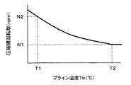
さらに、本実施形態では、電動モータ31bに出力される制御信号については、ブライン温度センサ43によって検出された検出物理量であるブライン温度Tbに基づいて、予め制御装置40に記憶されている制御マップを参照して決定される。
Furthermore, in the present embodiment, the control signal output to the
より具体的には、本実施形態の制御装置40は、図3に示される制御マップを予め記憶しており、ブライン温度Tb(℃)の上昇に伴って、圧縮機31の電動モータ31bの回転数(rpm)を低下させるように、すなわち、地中熱交換器11から流出したブラインの温度上昇に伴って、圧縮機31の冷媒吐出能力を低下させるように決定される。
More specifically, the
次に、ステップS4では、ステップS3で決定された制御状態が得られるように、制御装置40より各種アクチュエータ12、22、31b、33bに対して制御信号が出力される。
Next, in step S4, control signals are output from the
次のステップS5では、操作パネル44からの給湯機停止信号が制御装置40へ入力されている場合は、各種アクチュエータの作動を停止させて、ヒートポンプ式給湯機1の運転を停止させる。一方、給湯機停止信号が入力されていない場合は、予め定めた制御周期の間待機した後、ステップS2に戻るようになっている。
In the next step S5, when the hot water heater stop signal from the
従って、本実施形態のヒートポンプ式給湯機1では、圧縮機31から吐出された高温高圧の冷媒は、水−冷媒熱交換器32の冷媒通路32bに流入して、電動ポンプ22によって貯湯タンク21の下方側から水−冷媒熱交換器32の水通路32aに流入した給湯水と熱交換する。これにより、給湯水が加熱され、加熱された給湯水は、貯湯タンク21の上方側に貯留される。
Therefore, in the heat pump type
この際、本実施形態のヒートポンプサイクル30では、冷媒として二酸化炭素を採用し、超臨界冷凍サイクルを構成しているので、冷媒としてフロン等を採用する場合に対して、高圧冷媒の温度を上昇させることができる。その結果、水−冷媒熱交換器32において冷媒が給湯水に放熱する熱量を増加させて給湯水温度を高温化することができる。
At this time, in the
水−冷媒熱交換器32から流出した高圧冷媒は、電気式膨張弁33にて減圧膨張される。電気式膨張弁33にて減圧膨張された冷媒は、ブライン−冷媒熱交換器34の冷媒通路34bへ流入し、電動ポンプ12によってブライン−冷媒熱交換器34のブライン通路34aへ流入したブラインから吸熱して蒸発する。そして、ブライン−冷媒熱交換器34から流出した冷媒は、再び圧縮機31へ吸入される。
The high-pressure refrigerant flowing out of the water-
さらに、本実施形態では、制御装置40(具体的には、吐出能力制御手段40a)が、ブライン温度センサ43によって検出された検出物理量であるブライン温度Tbに基づいて、ブライン温度Tbの上昇に伴って、圧縮機31の電動モータ31bの回転数を低下させるので、地下熱に短期的な温度変化が生じても、地熱利用ヒートポンプ装置の運転を確実に安定させることができる。
Furthermore, in the present embodiment, the control device 40 (specifically, the discharge
このことをより詳細に説明する。地下熱が低下すると、ブライン温度Tbが低下して、ブライン−冷媒熱交換器34における冷媒蒸発圧力も低下する。このため、ブライン−冷媒熱交換器34の冷媒通路34bから流出して圧縮機31へ吸入される冷媒の密度が低下して、圧縮機31の冷媒吐出流量、すなわちヒートポンプサイクル30の循環冷媒流量が低下してしまう。
This will be described in more detail. When the underground heat decreases, the brine temperature Tb decreases, and the refrigerant evaporation pressure in the brine-
逆に、地下熱が上昇すると、ブライン温度Tbが上昇して、ブライン−冷媒熱交換器34における冷媒蒸発圧力も上昇する。このため、ブライン−冷媒熱交換器34の冷媒通路34bから流出して圧縮機31へ吸入される冷媒の密度が上昇して、圧縮機31の冷媒吐出流量、すなわちヒートポンプサイクル30の循環冷媒流量が増加してしまう。
Conversely, when the underground heat rises, the brine temperature Tb rises, and the refrigerant evaporation pressure in the brine-
従って、本実施形態のように、地下熱に相関を有する地中熱交換器11から流出した熱媒体の温度上昇に伴って、圧縮機31の冷媒吐出能力を低下させることで、圧縮機31の吐出冷媒流量を安定させて、水−冷媒熱交換器32から流出する給湯水の温度を確実に安定させることができる。その結果、地熱利用ヒートポンプ装置の運転を確実に安定させることができる。
Accordingly, as in the present embodiment, the refrigerant discharge capacity of the
(第2〜5実施形態)
第1実施形態では、熱媒体温度検出手段として、地中熱交換器11から流出したブラインの温度を検出するブライン温度センサ43を採用した例を説明したが、第2〜5実施形態では、それぞれ図4に示す熱媒体温度検出手段を採用している。
(Second to fifth embodiments)
In 1st Embodiment, although the example which employ | adopted the
なお、図4は、第1実施形態の図1に対応するヒートポンプ式給湯機1の全体構成図に対応する図面であって、第1実施形態と同一もしくは均等部分には同一の符号を付している。また、図4では、第2〜5実施形態における、それぞれの熱媒体温度検出手段を明確に示すために電気制御部の一部を省略しているが、これらの熱媒体温度検出手段についても第1実施形態と同様に制御装置40の入力側に接続されている。
FIG. 4 is a diagram corresponding to the overall configuration diagram of the heat pump
第2実施形態では、熱媒体温度検出手段として、ブライン−冷媒熱交換器34の冷媒通路34bへ流入した冷媒のうち、冷媒通路34b入口側冷媒の温度を検出する入口側冷媒温度センサ45を採用している。
In the second embodiment, an inlet-side
図4の全体構成図に示すように、ブライン−冷媒熱交換器34として、冷媒通路34bを流通する冷媒の流れ方向およびブライン通路34aを流通するブラインの流方向が同一方向となる熱交換器を採用する場合には、冷媒通路34b入口側冷媒の温度およびブライン通路34a入口側ブラインの温度は略同等となる。
As shown in the overall configuration diagram of FIG. 4, as the brine-
従って、熱媒体温度検出手段として、入口側冷媒温度センサ45を採用しても、実質的に、地中熱交換器11から流出したブラインの温度に応じて圧縮機31の冷媒吐出能力を制御できる。その結果、第1実施形態と同様に、地熱利用ヒートポンプ装置の運転を確実に安定させることができる。
Therefore, even if the inlet side
なお、本実施形態では、入口側冷媒温度センサ45として、ブライン−冷媒熱交換器34の冷媒通路34b入口側の表面温度を検出するサーミスタを採用しているが、もちろん、他の形式の熱媒体温度検出手段(例えば、熱電対等)を採用してもよいし、冷媒通路34b入口側の冷媒温度を直接検出してもよい。
In this embodiment, a thermistor that detects the surface temperature on the inlet side of the
第3実施形態では、熱媒体温度検出手段として、ブライン−冷媒熱交換器34の冷媒通路34b内の冷媒圧力を検出する冷媒蒸発圧力センサ46を採用している。冷媒通路34b内の冷媒圧力は、地下熱に相関を有する地中熱交換器11から流出したブラインの温度変化に伴って変化するので、地中熱交換器11から流出したブラインの温度に相関を有する物理量である。
In the third embodiment, a refrigerant
従って、第1実施形態と同様に、地熱利用ヒートポンプ装置の運転を確実に安定させることができる。なお、本実施形態では、図4に示すように、冷媒蒸発圧力センサ46が冷媒通路34b内の冷媒蒸発圧力を直接検出しているが、電気式膨張弁33出口側から圧縮機31吸入口側へ至るヒートポンプサイクル30の低圧側冷媒圧力を検出してもよい。
Therefore, similarly to the first embodiment, the operation of the geothermal heat pump device can be reliably stabilized. In the present embodiment, as shown in FIG. 4, the refrigerant
第4実施形態では、熱媒体温度検出手段として、ブライン−冷媒熱交換器34の冷媒通路34bから流出した冷媒の温度を検出する冷媒蒸発温度センサ47を採用している。冷媒通路34bから流出した冷媒の温度、ブライン−冷媒熱交換器34における冷媒蒸発温度(冷媒蒸発圧力)に相関を有する物理量である。
In 4th Embodiment, the refrigerant | coolant
従って、第1実施形態と同様に、地熱利用ヒートポンプ装置の運転を確実に安定させることができる。さらに、一般的に、圧力センサよりも安価な温度センサを採用できるので、低コストで、地熱利用ヒートポンプ装置の運転を確実に安定させることができる。 Therefore, similarly to the first embodiment, the operation of the geothermal heat pump device can be reliably stabilized. Furthermore, since a temperature sensor that is less expensive than a pressure sensor can be generally used, the operation of the geothermal heat pump device can be reliably stabilized at a low cost.
第5実施形態では、熱媒体温度検出手段として、ブライン−冷媒熱交換器34のブライン通路34aから流出したブラインの温度検出する流出ブライン温度センサ48を採用している。ブライン通路34aから流出したブラインの温度は、冷媒通路34aから流出した冷媒の温度とほぼ同等となる物理量である。従って、第1実施形態と同様に、地熱利用ヒートポンプ装置の運転を確実に安定させることができる。
In the fifth embodiment, an outflow
(他の実施形態)
本発明は上述の実施形態に限定されることなく、以下のように種々変形可能である。
(Other embodiments)
The present invention is not limited to the above-described embodiment, and can be variously modified as follows.
(1)上述の実施形態では、熱媒体温度検出手段が検出した1つの検出値を用いて圧縮機31の冷媒吐出能力を制御した例を説明したが、複数の種類の検出値を用いて、圧縮機31の冷媒吐出能力を制御してもよい。
(1) In the above-described embodiment, the example in which the refrigerant discharge capacity of the
例えば、ブライン−冷媒熱交換器34のブライン通路34aへ流入する流入側ブライン温度Tbiおよびブライン通路34aから流出する流出側ブライン温度Tboを用いて、Tbiおよび演算値Tbo−Tbiに基づいて圧縮機31の冷媒吐出能力を制御してもよい。
For example, using the inflow side brine temperature Tbi flowing into the
より具体的には、流入側ブライン温度Tbiの上昇に伴って、圧縮機31の冷媒吐出能力を低下させて、演算値Tbo−Tbiの値に応じて、その低下度合を変化させれば、地下熱の温度のみならず、ヒートポンプサイクル30の負荷状況に応じて、圧縮機31の作動を制御できる。
More specifically, if the refrigerant discharge capacity of the
(2)上述の実施形態では、本発明の地熱利用ヒートポンプ装置をヒートポンプ式給湯器に適用した例を説明したが、本発明の適用はこれに限定されない。例えば、空調装置等に適用してもよい。 (2) In the above-described embodiment, an example in which the geothermal heat pump device of the present invention is applied to a heat pump type water heater has been described, but the application of the present invention is not limited to this. For example, it may be applied to an air conditioner or the like.
さらに、上述の実施形態では、水−冷媒熱交換器32を放熱器として作用させて熱交換対象流体を加熱する加熱運転モードでヒートポンプサイクル30を作動させているが、さらに、ヒートポンプサイクル30の冷媒流路を切り替える流路切替手段を設け、水−冷媒熱交換器32を蒸発器として作用させる冷媒流路に切り替えて熱交換対象流体を冷却する冷却運転モードを実現可能に構成してもよい。
Further, in the above-described embodiment, the
(3)上述の第1実施形態では、図1に示すように、ブライン温度センサ43を、ヒートポンプ筐体35の外側に配置しているが、もちろん電動ポンプ12の下流側のヒートポンプ筐体35の内側に配置してもよい。
(3) In the first embodiment described above, as shown in FIG. 1, the
(4)上述の実施形態では、熱媒体温度検出手段が検出した検出値に基づいて、圧縮機31の作動を制御した例を説明したが、電気式膨張弁33の開度を制御しても同様の効果を得ることができる。
(4) In the above-described embodiment, the example in which the operation of the
(5)上述の実施形態では、圧縮機31として電動圧縮機を採用した例を説明したが、圧縮機31はこれに限定されない。例えば、エンジン駆動式の可変容量型圧縮機を採用してもよい。この場合は、可変容量型圧縮機の容量制御手段が吐出能力変更手段となる。また、エンジン駆動式の固定容量型圧縮機を採用してもよい。この場合は、エンジンと固定容量型圧縮機との動力伝達を断続する電磁クラッチが吐出能力変更手段となる。
(5) In the above-described embodiment, the example in which the electric compressor is adopted as the
(6)上述の実施形態のヒートポンプサイクル30に、ブライン−冷媒熱交換器34の冷媒通路34b流出冷媒の気液を分離して、余剰冷媒を蓄える気液分離手段としてのアキュムレータを設けてもよい。
(6) The
(7)上述の実施形態のヒートポンプサイクル30に、圧縮機31吸入冷媒と水−冷媒熱交換器32の冷媒通路32b流出冷媒とを熱交換させる内部熱交換器を設けてもよい。
(7) The
11 地中熱交換器
34 ブライン−冷媒熱交換器
31 圧縮機
31b 電動モータ
32 水−冷媒熱交換器
43 ブライン温度センサ
40 制御装置
40a 吐出能力制御手段
DESCRIPTION OF
Claims (6)
前記地中熱交換器(11)から流出した熱媒体と冷媒とを熱交換させる1次側熱交換器(34)と、
前記1次側熱交換器(34)から流出した冷媒を圧縮して吐出する圧縮機(31)と、
前記圧縮機(31)から吐出された冷媒と熱交換対象流体とを熱交換させる2次側熱交換器(32)と、
前記圧縮機(31)の冷媒吐出能力を変化させる吐出能力変更手段(31b)と、
前記吐出能力変更手段(31b)の作動を制御する吐出能力制御手段(40a)とを備える地熱利用ヒートポンプ装置であって、
さらに、前記地中熱交換器(11)から流出した熱媒体の温度と相関を有する物理量を検出する熱媒体温度検出手段(43)を備え、
前記吐出能力制御手段(40a)は、前記熱媒体温度検出手段(43)によって検出された検出物理量(Tb)に基づいて、前記地中熱交換器(11)から流出した熱媒体の温度の上昇に伴って、前記冷媒吐出能力を低下させるように、前記吐出能力変更手段(31b)の作動を制御することを特徴とする地熱利用ヒートポンプ装置。 An underground heat exchanger (11) that is buried in the ground and absorbs underground heat into the heat medium;
A primary heat exchanger (34) for exchanging heat between the heat medium flowing out of the underground heat exchanger (11) and the refrigerant;
A compressor (31) for compressing and discharging the refrigerant flowing out of the primary side heat exchanger (34);
A secondary heat exchanger (32) for exchanging heat between the refrigerant discharged from the compressor (31) and the heat exchange target fluid;
Discharge capacity changing means (31b) for changing the refrigerant discharge capacity of the compressor (31);
A geothermal heat pump device comprising discharge capacity control means (40a) for controlling the operation of the discharge capacity changing means (31b),
Furthermore, it comprises a heat medium temperature detecting means (43) for detecting a physical quantity having a correlation with the temperature of the heat medium flowing out from the underground heat exchanger (11),
The discharge capacity control means (40a) increases the temperature of the heat medium flowing out from the underground heat exchanger (11) based on the detected physical quantity (Tb) detected by the heat medium temperature detection means (43). Accordingly, the operation of the discharge capacity changing means (31b) is controlled so as to reduce the refrigerant discharge capacity.
Priority Applications (1)
| Application Number | Priority Date | Filing Date | Title |
|---|---|---|---|
| JP2008083217A JP2009236403A (en) | 2008-03-27 | 2008-03-27 | Geothermal use heat pump device |
Applications Claiming Priority (1)
| Application Number | Priority Date | Filing Date | Title |
|---|---|---|---|
| JP2008083217A JP2009236403A (en) | 2008-03-27 | 2008-03-27 | Geothermal use heat pump device |
Publications (1)
| Publication Number | Publication Date |
|---|---|
| JP2009236403A true JP2009236403A (en) | 2009-10-15 |
Family
ID=41250574
Family Applications (1)
| Application Number | Title | Priority Date | Filing Date |
|---|---|---|---|
| JP2008083217A Pending JP2009236403A (en) | 2008-03-27 | 2008-03-27 | Geothermal use heat pump device |
Country Status (1)
| Country | Link |
|---|---|
| JP (1) | JP2009236403A (en) |
Cited By (10)
| Publication number | Priority date | Publication date | Assignee | Title |
|---|---|---|---|---|
| JP2011226660A (en) * | 2010-04-15 | 2011-11-10 | Corona Corp | Geothermal heat pump device |
| WO2011142415A1 (en) * | 2010-05-14 | 2011-11-17 | 三浦工業株式会社 | Steam system |
| JP2012167902A (en) * | 2011-02-16 | 2012-09-06 | Corona Corp | Geothermal heat pump device |
| CN103162410A (en) * | 2013-04-11 | 2013-06-19 | 李家海 | Energy-saving heat pump water heater utilizing well water heat energy to compensate heat source |
| CN103216921A (en) * | 2013-03-08 | 2013-07-24 | 天津美意空调设备销售有限公司 | Control device for ground source heat pump unit |
| JP2013249978A (en) * | 2012-05-30 | 2013-12-12 | Daikin Industries Ltd | Underground heat exchanger and heat pump |
| CN103629848A (en) * | 2012-08-27 | 2014-03-12 | 昆山开思拓节能技术有限公司 | Geotherm cooling device |
| CN106568231A (en) * | 2016-11-14 | 2017-04-19 | 上海电机学院 | Heat and cold preparation system based on geothermal energy |
| CN108050718A (en) * | 2017-12-08 | 2018-05-18 | 北京中煤矿山工程有限公司 | A kind of freezing engineering recycling waste heat recovery system and method |
| CN114517989A (en) * | 2022-02-25 | 2022-05-20 | 中国地质调查局水文地质环境地质调查中心 | Exploitation device and exploitation method for utilization of geothermal energy of dry hot rock |
Citations (5)
| Publication number | Priority date | Publication date | Assignee | Title |
|---|---|---|---|---|
| JPH0545869B2 (en) * | 1986-03-03 | 1993-07-12 | Ebara Mfg | |
| JPH0996476A (en) * | 1995-10-02 | 1997-04-08 | Mitsubishi Heavy Ind Ltd | Manufacture of supercooling water type chilled water |
| JP2001183030A (en) * | 1999-10-12 | 2001-07-06 | Kubota Corp | Geothermal sampling testing device |
| JP2003139419A (en) * | 2001-11-05 | 2003-05-14 | Denso Corp | Hot water supply system |
| JP2007064540A (en) * | 2005-08-30 | 2007-03-15 | Denso Corp | Geothermal heat pump type water heater |
-
2008
- 2008-03-27 JP JP2008083217A patent/JP2009236403A/en active Pending
Patent Citations (5)
| Publication number | Priority date | Publication date | Assignee | Title |
|---|---|---|---|---|
| JPH0545869B2 (en) * | 1986-03-03 | 1993-07-12 | Ebara Mfg | |
| JPH0996476A (en) * | 1995-10-02 | 1997-04-08 | Mitsubishi Heavy Ind Ltd | Manufacture of supercooling water type chilled water |
| JP2001183030A (en) * | 1999-10-12 | 2001-07-06 | Kubota Corp | Geothermal sampling testing device |
| JP2003139419A (en) * | 2001-11-05 | 2003-05-14 | Denso Corp | Hot water supply system |
| JP2007064540A (en) * | 2005-08-30 | 2007-03-15 | Denso Corp | Geothermal heat pump type water heater |
Cited By (13)
| Publication number | Priority date | Publication date | Assignee | Title |
|---|---|---|---|---|
| JP2011226660A (en) * | 2010-04-15 | 2011-11-10 | Corona Corp | Geothermal heat pump device |
| WO2011142415A1 (en) * | 2010-05-14 | 2011-11-17 | 三浦工業株式会社 | Steam system |
| JP2012167902A (en) * | 2011-02-16 | 2012-09-06 | Corona Corp | Geothermal heat pump device |
| JP2013249978A (en) * | 2012-05-30 | 2013-12-12 | Daikin Industries Ltd | Underground heat exchanger and heat pump |
| CN103629848A (en) * | 2012-08-27 | 2014-03-12 | 昆山开思拓节能技术有限公司 | Geotherm cooling device |
| CN103216921A (en) * | 2013-03-08 | 2013-07-24 | 天津美意空调设备销售有限公司 | Control device for ground source heat pump unit |
| CN103162410A (en) * | 2013-04-11 | 2013-06-19 | 李家海 | Energy-saving heat pump water heater utilizing well water heat energy to compensate heat source |
| CN103162410B (en) * | 2013-04-11 | 2015-11-25 | 李家海 | A kind of energy-saving water heater utilizing well water thermal compensation thermal source |
| CN106568231A (en) * | 2016-11-14 | 2017-04-19 | 上海电机学院 | Heat and cold preparation system based on geothermal energy |
| CN108050718A (en) * | 2017-12-08 | 2018-05-18 | 北京中煤矿山工程有限公司 | A kind of freezing engineering recycling waste heat recovery system and method |
| CN108050718B (en) * | 2017-12-08 | 2020-02-21 | 北京中煤矿山工程有限公司 | Waste heat recycling system and method for freezing engineering |
| CN114517989A (en) * | 2022-02-25 | 2022-05-20 | 中国地质调查局水文地质环境地质调查中心 | Exploitation device and exploitation method for utilization of geothermal energy of dry hot rock |
| CN114517989B (en) * | 2022-02-25 | 2023-06-23 | 中国地质调查局水文地质环境地质调查中心 | Exploitation device and exploitation method for utilizing geothermal energy of dry-hot rock |
Similar Documents
| Publication | Publication Date | Title |
|---|---|---|
| JP2009236403A (en) | Geothermal use heat pump device | |
| JP5642207B2 (en) | Refrigeration cycle apparatus and refrigeration cycle control method | |
| JP5121922B2 (en) | Air conditioning and hot water supply complex system | |
| JP2009133547A (en) | Refrigerating cycle apparatus | |
| JP5524571B2 (en) | Heat pump equipment | |
| JP5855279B2 (en) | Air conditioner | |
| JPWO2009098751A1 (en) | Air conditioning and hot water supply complex system | |
| JP5094942B2 (en) | Heat pump equipment | |
| JP2009243793A (en) | Heat pump type hot water supply outdoor unit | |
| JP6289734B2 (en) | Air conditioning and hot water supply complex system | |
| JP5300806B2 (en) | Heat pump equipment | |
| EP2770278B1 (en) | Water heater | |
| JP5481838B2 (en) | Heat pump cycle equipment | |
| JP2007139244A (en) | Refrigeration device | |
| JP5659560B2 (en) | Refrigeration cycle equipment | |
| JP6267952B2 (en) | Refrigeration cycle equipment | |
| JP2009092258A (en) | Refrigerating cycle device | |
| JP2009264717A (en) | Heat pump hot water system | |
| JP5934916B2 (en) | Refrigeration cycle apparatus and hot water generator provided with the same | |
| JP2011257098A (en) | Heat pump cycle device | |
| JP6758506B2 (en) | Air conditioner | |
| JP2010025517A (en) | Heat pump type water heater | |
| JP2012007751A (en) | Heat pump cycle device | |
| JP2009281631A (en) | Heat pump unit | |
| JP2011153789A (en) | Refrigerating cycle device |
Legal Events
| Date | Code | Title | Description |
|---|---|---|---|
| A621 | Written request for application examination |
Free format text: JAPANESE INTERMEDIATE CODE: A621 Effective date: 20100409 |
|
| A977 | Report on retrieval |
Free format text: JAPANESE INTERMEDIATE CODE: A971007 Effective date: 20111116 |
|
| A131 | Notification of reasons for refusal |
Free format text: JAPANESE INTERMEDIATE CODE: A131 Effective date: 20111129 |
|
| A02 | Decision of refusal |
Free format text: JAPANESE INTERMEDIATE CODE: A02 Effective date: 20120612 |
|
| A521 | Written amendment |
Effective date: 20120910 Free format text: JAPANESE INTERMEDIATE CODE: A523 |
|
| A911 | Transfer of reconsideration by examiner before appeal (zenchi) |
Free format text: JAPANESE INTERMEDIATE CODE: A911 Effective date: 20120918 |
|
| A912 | Removal of reconsideration by examiner before appeal (zenchi) |
Effective date: 20121102 Free format text: JAPANESE INTERMEDIATE CODE: A912 |