JP2009236182A - Control device for continuously variable transmission - Google Patents
Control device for continuously variable transmission Download PDFInfo
- Publication number
- JP2009236182A JP2009236182A JP2008081318A JP2008081318A JP2009236182A JP 2009236182 A JP2009236182 A JP 2009236182A JP 2008081318 A JP2008081318 A JP 2008081318A JP 2008081318 A JP2008081318 A JP 2008081318A JP 2009236182 A JP2009236182 A JP 2009236182A
- Authority
- JP
- Japan
- Prior art keywords
- continuously variable
- variable transmission
- valve
- control
- rotational speed
- Prior art date
- Legal status (The legal status is an assumption and is not a legal conclusion. Google has not performed a legal analysis and makes no representation as to the accuracy of the status listed.)
- Pending
Links
Images


Classifications
-
- F—MECHANICAL ENGINEERING; LIGHTING; HEATING; WEAPONS; BLASTING
- F16—ENGINEERING ELEMENTS AND UNITS; GENERAL MEASURES FOR PRODUCING AND MAINTAINING EFFECTIVE FUNCTIONING OF MACHINES OR INSTALLATIONS; THERMAL INSULATION IN GENERAL
- F16H—GEARING
- F16H61/00—Control functions within control units of change-speed- or reversing-gearings for conveying rotary motion ; Control of exclusively fluid gearing, friction gearing, gearings with endless flexible members or other particular types of gearing
- F16H61/66—Control functions within control units of change-speed- or reversing-gearings for conveying rotary motion ; Control of exclusively fluid gearing, friction gearing, gearings with endless flexible members or other particular types of gearing specially adapted for continuously variable gearings
- F16H61/662—Control functions within control units of change-speed- or reversing-gearings for conveying rotary motion ; Control of exclusively fluid gearing, friction gearing, gearings with endless flexible members or other particular types of gearing specially adapted for continuously variable gearings with endless flexible members
- F16H61/66254—Control functions within control units of change-speed- or reversing-gearings for conveying rotary motion ; Control of exclusively fluid gearing, friction gearing, gearings with endless flexible members or other particular types of gearing specially adapted for continuously variable gearings with endless flexible members controlling of shifting being influenced by a signal derived from the engine and the main coupling
- F16H61/66259—Control functions within control units of change-speed- or reversing-gearings for conveying rotary motion ; Control of exclusively fluid gearing, friction gearing, gearings with endless flexible members or other particular types of gearing specially adapted for continuously variable gearings with endless flexible members controlling of shifting being influenced by a signal derived from the engine and the main coupling using electrical or electronical sensing or control means
-
- F—MECHANICAL ENGINEERING; LIGHTING; HEATING; WEAPONS; BLASTING
- F16—ENGINEERING ELEMENTS AND UNITS; GENERAL MEASURES FOR PRODUCING AND MAINTAINING EFFECTIVE FUNCTIONING OF MACHINES OR INSTALLATIONS; THERMAL INSULATION IN GENERAL
- F16H—GEARING
- F16H61/00—Control functions within control units of change-speed- or reversing-gearings for conveying rotary motion ; Control of exclusively fluid gearing, friction gearing, gearings with endless flexible members or other particular types of gearing
- F16H61/66—Control functions within control units of change-speed- or reversing-gearings for conveying rotary motion ; Control of exclusively fluid gearing, friction gearing, gearings with endless flexible members or other particular types of gearing specially adapted for continuously variable gearings
- F16H61/662—Control functions within control units of change-speed- or reversing-gearings for conveying rotary motion ; Control of exclusively fluid gearing, friction gearing, gearings with endless flexible members or other particular types of gearing specially adapted for continuously variable gearings with endless flexible members
- F16H2061/66204—Control for modifying the ratio control characteristic
- F16H2061/66218—Control for modifying the ratio control characteristic dependent on control input parameters other than ambient conditions or driver's choice
-
- F—MECHANICAL ENGINEERING; LIGHTING; HEATING; WEAPONS; BLASTING
- F16—ENGINEERING ELEMENTS AND UNITS; GENERAL MEASURES FOR PRODUCING AND MAINTAINING EFFECTIVE FUNCTIONING OF MACHINES OR INSTALLATIONS; THERMAL INSULATION IN GENERAL
- F16H—GEARING
- F16H59/00—Control inputs to control units of change-speed-, or reversing-gearings for conveying rotary motion
- F16H59/68—Inputs being a function of gearing status
- F16H59/72—Inputs being a function of gearing status dependent on oil characteristics, e.g. temperature, viscosity
Abstract
Description
本発明は、無段変速機の制御装置に関し、特に、無段変速機の目標入力軸回転数の上限値を出力軸回転数に応じて設定する技術に関する。 The present invention relates to a control device for a continuously variable transmission, and more particularly to a technique for setting an upper limit value of a target input shaft rotational speed of a continuously variable transmission according to an output shaft rotational speed.
従来より、プライマリプーリとセカンダリプーリとを金属ベルトで連結し、これらのプーリの幅を変化させることにより、無段階に変速を行なうベルト式無段変速機等の無段変速機(CVT:Continuously Variable Transmission)が知られている。このベルト式無段変速機を搭載した車両においては、プライマリプーリの油圧シリンダに作動油を供給したり、油圧シリンダから作動油を排出したりして、プーリの幅が変化され、変速が行なわれる。 Conventionally, a continuously variable transmission (CVT) such as a belt-type continuously variable transmission that continuously changes gears by connecting a primary pulley and a secondary pulley with a metal belt and changing the width of these pulleys. Transmission) is known. In a vehicle equipped with this belt-type continuously variable transmission, the hydraulic oil is supplied to the hydraulic cylinder of the primary pulley or the hydraulic oil is discharged from the hydraulic cylinder, so that the pulley width is changed to perform a shift. .
無段変速機に用いられる作動油の温度は、無段変速機から発せられた熱により上昇し得る。作動油の粘度は温度に変化し得る。したがって、作動油の温度が過剰になると、無段変速機の制御性が悪化し得る。そこで、作動油の温度上昇を制限することが必要である。 The temperature of the hydraulic oil used for the continuously variable transmission can be increased by heat generated from the continuously variable transmission. The viscosity of the hydraulic oil can change with temperature. Therefore, when the temperature of the hydraulic oil becomes excessive, the controllability of the continuously variable transmission can be deteriorated. Therefore, it is necessary to limit the temperature rise of the hydraulic oil.
特開平9−217824号公報(特許文献1)は、無段変速機がマニュアルレンジであり、作動油温が第1設定値以上であり、かつ、入力側回転数(入力軸回転数)が設定回転数以上である場合、入力側回転数が設定回転数まで低下されるような変速比に変速制御する無段変速機の変速制御装置を開示する。 In Japanese Patent Laid-Open No. 9-217824 (Patent Document 1), the continuously variable transmission is in the manual range, the hydraulic oil temperature is equal to or higher than the first set value, and the input side rotational speed (input shaft rotational speed) is set. Disclosed is a transmission control device for a continuously variable transmission that performs shift control to a gear ratio such that the input side rotational speed is reduced to a set rotational speed when the rotational speed is equal to or higher than the rotational speed.
この公報に記載の変速制御装置によれば、入力側回転数が設定回転数以下に規制されるため、作動油温の上昇を防止することができる。
無段変速機の発熱量は運転状態に応じて異なる。そのため、特開平9−217824号公報に記載の変速制御装置のように入力軸回転数を低下した場合であっても、無段変速機の発熱量が大きい場合があり得る。この場合、作動油の温度が上昇し得る。 The amount of heat generated by the continuously variable transmission varies depending on the operating state. Therefore, even if the input shaft rotational speed is reduced as in the shift control device described in JP-A-9-217824, the continuously variable transmission may generate a large amount of heat. In this case, the temperature of the hydraulic oil can rise.
本発明は、上述の課題を解決するためになされたものであって、その目的は、作動油の温度を適正な状態に維持することができる無段変速機の制御装置を提供することである。 The present invention has been made to solve the above-described problems, and an object of the present invention is to provide a control device for a continuously variable transmission that can maintain the temperature of hydraulic oil in an appropriate state. .
第1の発明に係る無段変速機の制御装置は、無段変速機の出力軸回転数を検出するための手段と、無段変速機の目標入力軸回転数の上限値を、無段変速機の出力軸回転数に応じて設定するための設定手段と、上限値以下になるように目標入力軸回転数を設定するための手段と、無段変速機の入力軸回転数が目標入力軸回転数になるように制御するための手段とを備える。 A control device for a continuously variable transmission according to a first aspect of the present invention includes a means for detecting an output shaft rotational speed of a continuously variable transmission and an upper limit value of a target input shaft rotational speed of the continuously variable transmission. Setting means for setting according to the output shaft speed of the machine, means for setting the target input shaft speed so as to be less than or equal to the upper limit value, and the input shaft speed of the continuously variable transmission is the target input shaft And a means for controlling the rotation speed.
この構成によると、無段変速機の目標入力軸回転数の上限値が、無段変速機の出力軸回転数に応じて設定される。目標入力軸回転数は、上限値以下になるように設定される。無段変速機の入力軸回転数は、目標入力軸回転数になるように制御される。たとえば、変速比が小さくされる。これにより、無段変速機の発熱量に影響を与える出力軸回転数に応じて、無段変速機の入力軸回転数を制御することができる。そのため、たとえば出力軸回転数が高く、発熱量が大きくなり易い運転状態では、アップアップシフトすることにより入
力軸回転数を低下して、発熱量を制限することができる。そのため、作動油の温度を適正な状態に維持することができる無段変速機の制御装置を提供することができる。
According to this configuration, the upper limit value of the target input shaft rotational speed of the continuously variable transmission is set according to the output shaft rotational speed of the continuously variable transmission. The target input shaft speed is set to be equal to or less than the upper limit value. The input shaft rotation speed of the continuously variable transmission is controlled to be the target input shaft rotation speed. For example, the gear ratio is reduced. Thereby, the input shaft rotation speed of the continuously variable transmission can be controlled in accordance with the output shaft rotation speed that affects the heat generation amount of the continuously variable transmission. For this reason, for example, in an operating state where the output shaft rotational speed is high and the amount of heat generation is likely to increase, up-shifting can reduce the input shaft rotational speed and limit the amount of heat generation. Therefore, it is possible to provide a control device for a continuously variable transmission that can maintain the temperature of hydraulic oil in an appropriate state.
第2の発明に係る無段変速機の制御装置においては、第1の発明の構成に加え、設定手段は、無段変速機の出力軸回転数が高いほど上限値がより低くなるように設定するための手段を含む。 In the continuously variable transmission control device according to the second invention, in addition to the configuration of the first invention, the setting means sets the upper limit value to be lower as the output shaft rotational speed of the continuously variable transmission is higher. Means for doing so.
この構成によると、出力軸回転数が高く、発熱量が大きくなり易い運転状態では、入力軸回転数を低下して、発熱量を制限することができる。 According to this configuration, in an operation state in which the output shaft rotational speed is high and the heat generation amount tends to increase, the input shaft rotational speed can be reduced to limit the heat generation amount.
第3の発明に係る無段変速機の制御装置は、第1または2の発明の構成に加え、無段変速機に供給される作動油の温度を検出するための手段をさらに備える。設定手段は、作動油の温度がしきい値よりも高い場合、上限値を出力軸回転数に応じて設定するため手段を含む。 The control device for a continuously variable transmission according to the third invention further includes means for detecting the temperature of the hydraulic oil supplied to the continuously variable transmission in addition to the configuration of the first or second invention. The setting means includes means for setting the upper limit value according to the output shaft rotational speed when the temperature of the hydraulic oil is higher than the threshold value.
この構成によると、作動油の温度がしきい値よりも高い場合、目標入力軸回転数の上限値が出力軸回転数に応じて設定される。これにより、作動油の温度が高いために無段変速機の制御性が悪化し得る場合には、発熱量を制限することができる。そのため、無段変速機の制御性を悪化し難くすることができる。 According to this configuration, when the temperature of the hydraulic oil is higher than the threshold value, the upper limit value of the target input shaft speed is set according to the output shaft speed. Thereby, when the controllability of the continuously variable transmission can be deteriorated because the temperature of the hydraulic oil is high, the heat generation amount can be limited. Therefore, the controllability of the continuously variable transmission can be made difficult to deteriorate.
以下、図面を参照しつつ、本発明の実施の形態について説明する。以下の説明では、同一の部品には同一の符号を付してある。それらの名称および機能も同一である。したがって、それらについての詳細な説明は繰返さない。 Hereinafter, embodiments of the present invention will be described with reference to the drawings. In the following description, the same parts are denoted by the same reference numerals. Their names and functions are also the same. Therefore, detailed description thereof will not be repeated.
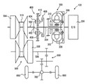
図1を参照して、本実施の形態に係る制御装置を搭載した車両について説明する。この車両に搭載された駆動装置100のエンジン200の出力は、トルクコンバータ300および前後進切換装置400を介して、無段変速機500に入力される。無段変速機500の出力は、減速歯車600および差動歯車装置700に伝達され、左右の駆動輪800へ分配される。駆動装置100は、後述するECU(Electronic Control Unit)900により制御される。
A vehicle equipped with a control device according to the present embodiment will be described with reference to FIG. The output of the
トルクコンバータ300は、エンジン200のクランク軸に連結されたポンプ翼車302と、タービン軸304を介して前後進切換装置400に連結されたタービン翼車306とから構成されている。ポンプ翼車302およびタービン翼車306の間にはロックアップクラッチ308が設けられている。ロックアップクラッチ308は、係合側油室および解放側油室に対する油圧供給が切換えられることにより、係合または解放されるようになっている。
The
ロックアップクラッチ308が完全係合させられることにより、ポンプ翼車302およびタービン翼車306は一体的に回転させられる。ポンプ翼車302には、無段変速機500を変速制御したり、ベルト挟圧力を発生させたり、各部に潤滑のための作動油を供給したりするための油圧を発生する機械式のオイルポンプ310が設けられている。
When the
前後進切換装置400は、ダブルピニオン型の遊星歯車装置から構成されている。トルクコンバータ300のタービン軸304はサンギヤ402に連結されている。無段変速機500の入力軸502はキャリア404に連結されている。キャリア404とサンギヤ402とはフォワードクラッチ406を介して連結されている。リングギヤ408は、リバースブレーキ410を介してハウジングに固定される。フォワードクラッチ406およびリバースブレーキ410は油圧シリンダによって摩擦係合させられる。フォワードクラッ
チ406の入力回転数は、タービン軸304の回転数、すなわちタービン回転数NTと同じである。
The forward /
フォワードクラッチ406が係合させられるとともに、リバースブレーキ410が解放されることにより、前後進切換装置400は前進用係合状態となる。この状態で、前進方向の駆動力が無段変速機500に伝達される。リバースブレーキ410が係合させられるとともにフォワードクラッチ406が解放されることにより、前後進切換装置400は後進用係合状態となる。この状態で、入力軸502はタービン軸304に対して逆方向へ回転させられる。これにより、後進方向の駆動力が無段変速機500に伝達される。フォワードクラッチ406およびリバースブレーキ410が共に解放されると、前後進切換装置400は動力伝達を遮断するニュートラル状態になる。
When the
無段変速機500は、入力軸502に設けられたプライマリプーリ504と、出力軸506に設けられたセカンダリプーリ508と、これらのプーリに巻き掛けられた伝動ベルト510とから構成される。各プーリと伝動ベルト510との間の摩擦力を利用して、動力伝達が行われる。
The continuously
各プーリは溝幅が可変であるように、油圧シリンダから構成されている。プライマリプーリ504の油圧シリンダの油圧が制御されることにより、各プーリの溝幅が変化する。これにより、伝動ベルト510の掛かり径が変更され、変速比GR(=プライマリプーリ回転数NIN/セカンダリプーリ回転数NOUT)が連続的に変化させられる。なお、ベルト式の無段変速機500の代わりに、チェーン式もしくはトロイダル式の無段変速機を用いるようにしてもよい。
Each pulley is composed of a hydraulic cylinder so that the groove width is variable. By controlling the hydraulic pressure of the hydraulic cylinder of the
図2に示すように、ECU900には、エンジン回転数センサ902、タービン回転数センサ904、車速センサ906、スロットル開度センサ908、冷却水温センサ910、油温センサ912、アクセル開度センサ914、フットブレーキスイッチ916、ポジションセンサ918、プライマリプーリ回転数センサ922およびセカンダリプーリ回転数センサ924が接続されている。
As shown in FIG. 2, the
エンジン回転数センサ902は、エンジン200の回転数(エンジン回転数)NEを検出する。タービン回転数センサ904は、タービン軸304の回転数(タービン回転数)NTを検出する。車速センサ906は、車速Vを検出する。スロットル開度センサ908は、電子スロットルバルブの開度THAを検出する。冷却水温センサ910は、エンジン200の冷却水温TWを検出する。油温センサ912は、無段変速機500の作動に用いられる作動油の温度(以下、油温とも記載する)THOを検出する。アクセル開度センサ914は、アクセルペダルの開度ACCを検出する。フットブレーキスイッチ916は、フットブレーキの操作の有無を検出する。ポジションセンサ918は、シフトポジションと対応する位置に設けられた接点がONであるかOFFであるかを判別することにより、シフトレバー920のポジションPSHを検出する。プライマリプーリ回転数センサ922は、プライマリプーリ504の回転数(入力軸回転数)NINを検出する。セカンダリプーリ回転数センサ924は、セカンダリプーリ508の回転数(出力軸回転数)NOUTを検出する。各センサの検出結果を表す信号が、ECU900に送信される。タービン回転数NTは、フォワードクラッチ406が係合された前進走行時にはプライマリプーリ回転数NINと一致する。車速Vは、セカンダリプーリ回転数NOUTと対応した値になる。したがって、車両が停車状態にあり、かつフォワードクラッチ406が係合された状態では、タービン回転数NTは0となる。
The
ECU900は、CPU(Central Processing Unit)、メモリおよび入出力インターフェースなどを含む。CPUはメモリに記憶されたプログラムに従って信号処理を行なう
。これにより、エンジン200の出力制御、無段変速機500の変速制御、ベルト挟圧力制御、フォワードクラッチ406の係合/解放制御およびリバースブレーキ410の係合/解放制御などを実行する。
エンジン200の出力制御は電子スロットルバルブ1000、燃料噴射装置1100、点火装置1200などによって行なわれる。無段変速機500の変速制御、ベルト挟圧力制御、フォワードクラッチ406の係合/解放制御およびリバースブレーキ410の係合/解放制御は、油圧制御回路2000によって行なわれる。
Output control of the
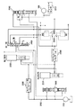
図3を参照して、油圧制御回路2000の一部について説明する。なお、以下に説明する油圧制御回路2000は一例であって、これに限らない。
A part of the
オイルポンプ310が発生した油圧は、ライン圧油路2002を介してプライマリレギュレータバルブ2100、モジュレータバルブ(1)2310およびモジュレータバルブ(3)2330に供給される。
The hydraulic pressure generated by the
プライマリレギュレータバルブ2100には、SLTリニアソレノイドバルブ2200およびSLSリニアソレノイドバルブ2210のいずれか一方から選択的に制御圧が供給される。本実施の形態において、SLTリニアソレノイドバルブ2200およびSLSリニアソレノイドバルブ2210の両方は、ノーマルオープン(非通電時に出力される油圧が最大になる)のソレノイドバルブである。なお、SLTリニアソレノイドバルブ2200およびSLSリニアソレノイドバルブ2210がノーマルクローズ(非通電時に出力される油圧が最小(「0」)になる)であるようにしてもよい。
The
プライマリレギュレータバルブ2100のスプールは、供給された制御圧に応じて上下に摺動する。これにより、オイルポンプ310で発生した油圧がプライマリレギュレータバルブ2100により調圧(調整)される。プライマリレギュレータバルブ2100により調圧された油圧がライン圧PLとして用いられる。本実施の形態においては、プライマリレギュレータバルブ2100に供給される制御圧が高いほど、ライン圧PLがより高くなる。なお、プライマリレギュレータバルブ2100に供給される制御圧が高いほど、ライン圧PLがより低くなるようにしてもよい。
The spool of the
SLTリニアソレノイドバルブ2200およびSLSリニアソレノイドバルブ2210には、ライン圧PLを元圧としてモジュレータバルブ(3)2330により調圧された油圧が供給される。
The SLT
SLTリニアソレノイドバルブ2200およびSLSリニアソレノイドバルブ2210は、ECU900から送信されたデューティ信号(デューティ値)によって決まる電流値に応じて制御圧を発生させる。
SLT
SLTリニアソレノイドバルブ2200の制御圧(出力油圧)およびSLSリニアソレノイドバルブ2210の制御圧(出力油圧)うち、プライマリレギュレータバルブ2100へ供給される制御圧は、コントロールバルブ2400により選択される。
Of the control pressure (output hydraulic pressure) of the SLT
コントロールバルブ2400のスプールが図3において(A)の状態(左側の状態)にある場合、SLTリニアソレノイドバルブ2200からプライマリレギュレータバルブ2100へ制御圧が供給される。すなわち、SLTリニアソレノイドバルブ2200の制御圧に応じて、ライン圧PLが制御される。
When the spool of the
コントロールバルブ2400のスプールが図3において(B)の状態(右側の状態)に
ある場合、SLSリニアソレノイドバルブ2210からプライマリレギュレータバルブ2100へ制御圧が供給される。すなわち、SLSリニアソレノイドバルブ2210の制御圧に応じて、ライン圧PLが制御される。
When the spool of the
なお、コントロールバルブ2400のスプールが図3において(B)の状態にある場合、SLTリニアソレノイドバルブ2200の制御圧は、後述するマニュアルバルブ2600に供給される。
When the spool of the
コントロールバルブ2400のスプールは、スプリングにより一方向へ付勢される。このスプリングの付勢力に対向するように、変速制御用デューティソレノイド(1)2510および変速制御用デューティソレノイド(2)2520から油圧が供給される。
The spool of the
変速制御用デューティソレノイド(1)2510および変速制御用デューティソレノイド(2)2520は、ECU900から送信されたデューティ信号(デューティ値)によって決まる電流値に応じた油圧(制御圧)を出力する。
Shift control duty solenoid (1) 2510 and shift control duty solenoid (2) 2520 output a hydraulic pressure (control pressure) corresponding to a current value determined by a duty signal (duty value) transmitted from
変速制御用デューティソレノイド(1)2510および変速制御用デューティソレノイド(2)2520の両方からコントロールバルブ2400に油圧が供給された場合、コントロールバルブ2400のスプールは図3において(B)の状態になる。
When hydraulic pressure is supplied to the
変速制御用デューティソレノイド(1)2510および変速制御用デューティソレノイド(2)2520の少なくともいずれか一方からコントロールバルブ2400に油圧が供給されていない場合、コントロールバルブ2400のスプールは、スプリングの付勢力により図3において(A)の状態になる。
When hydraulic pressure is not supplied to the
変速制御用デューティソレノイド(1)2510および変速制御用デューティソレノイド(2)2520には、モジュレータバルブ(4)2340により調圧された油圧が供給される。モジュレータバルブ(4)2340は、モジュレータバルブ(3)2330から供給された油圧を一定の圧力に調圧する。 The hydraulic pressure adjusted by the modulator valve (4) 2340 is supplied to the shift control duty solenoid (1) 2510 and the shift control duty solenoid (2) 2520. The modulator valve (4) 2340 regulates the hydraulic pressure supplied from the modulator valve (3) 2330 to a constant pressure.
モジュレータバルブ(1)2310は、ライン圧PLを元圧として調圧された油圧を出力する。モジュレータバルブ(1)2310から出力された油圧は、セカンダリプーリ508の油圧シリンダに供給される。セカンダリプーリ508の油圧シリンダには、伝動ベルト510が滑りを生じないような油圧が供給される。
The modulator valve (1) 2310 outputs a hydraulic pressure that is regulated using the line pressure PL as a source pressure. The hydraulic pressure output from the modulator valve (1) 2310 is supplied to the hydraulic cylinder of the
モジュレータバルブ(1)2310には、軸方向へ移動可能なスプールおよびそのスプールを一方へ付勢するスプリングが設けられている。モジュレータバルブ(1)2310は、ECU900によりデューティ制御されるSLSリニアソレノイドバルブ2210の出力油圧をパイロット圧として、モジュレータバルブ(1)2310に導入されるライン圧PLを調圧する。モジュレータバルブ(3)により調圧された油圧は、セカンダリプーリ508の油圧シリンダに供給される。モジュレータバルブ(1)2310からの出力油圧に応じてベルト挟圧力が増減させられる。
The modulator valve (1) 2310 is provided with a spool that can move in the axial direction and a spring that biases the spool to one side. Modulator valve (1) 2310 regulates line pressure PL introduced to modulator valve (1) 2310 using the output hydraulic pressure of SLS
SLSリニアソレノイドバルブ2210は、アクセル開度ACCおよび変速比GRをパラメータとしたマップに従い、ベルト滑りが生じないベルト挟圧力になるように制御される。具体的には、SLSリニアソレノイドバルブ2210に対する励磁電流をベルト挟圧力に対応するデューティ比で制御する。なお、加減速時などに伝達トルクが急に変化する場合には、ベルト挟圧力を増大補正してベルト滑りを抑制してもよい。
The SLS
セカンダリプーリ508の油圧シリンダに供給される油圧は、プレッシャセンサ231
2により検出される。
The hydraulic pressure supplied to the hydraulic cylinder of the
2 is detected.
図4を参照して、マニュアルバルブ2600について説明する。マニュアルバルブ2600は、シフトレバー920の操作に従って機械的に切換えられる。これにより、フォワードクラッチ406およびリバースブレーキ410は係合させられたり、解放させられたりする。
The
シフトレバー920は、駐車用の「P」ポジション、後進走行用の「R」ポジション、動力伝達を遮断する「N」ポジション、前進走行用の「D」ポジションおよび「B」ポジションへ操作される。
「P」ポジションおよび「N」ポジションでは、フォワードクラッチ406およびリバースブレーキ410内の油圧は、マニュアルバルブ2600からドレンされる。これにより、フォワードクラッチ406およびリバースブレーキ410は解放される。
In the “P” position and the “N” position, the hydraulic pressure in the
「R」ポジションでは、マニュアルバルブ2600からリバースブレーキ410に油圧が供給される。これによりリバースブレーキ410が係合させられる。一方、フォワードクラッチ406内の油圧がマニュアルバルブ2600からドレンされる。これによりフォワードクラッチ406が解放される。
In the “R” position, hydraulic pressure is supplied from the
コントロールバルブ2400が図4において(A)の状態(左側の状態)にある場合、図示しないモジュレータバルブ(2)から供給されたモジュレータ圧PMが、コントロールバルブ2400を介してマニュアルバルブ2600に供給される。このモジュレータ圧PMによりリバースブレーキ410が係合状態に保持される。
When the
コントロールバルブ2400が図4において(B)の状態(右側の状態)にある場合、SLTリニアソレノイドバルブ2200により調圧された油圧が、マニュアルバルブ2600に供給される。SLTリニアソレノイドバルブ2200により油圧を調圧することにより、リバースブレーキ410が緩やかに係合され、係合時のショックが抑制される。
When the
また、コントロールバルブ2400が図4において(B)の状態(右側の状態)にある場合において、SLTリニアソレノイドバルブ2200のデューティ比を100%にし、通電量を最大にすると、SLTリニアソレノイドバルブ2200から油圧が出力されなくなり、リバースブレーキ410に供給される油圧が「0」になる。すなわち、SLTリニアソレノイドバルブ2200を介してリバースブレーキ410から油圧がドレンされ、リバースブレーキ410が解放される。
Further, when the
「D」ポジションおよび「B」ポジションでは、マニュアルバルブ2600からフォワードクラッチ406に油圧が供給される。これによりフォワードクラッチ406が係合させられる。一方、リバースブレーキ410内の油圧がマニュアルバルブ2600からドレンされる。これによりリバースブレーキ410が解放される。
In the “D” position and the “B” position, hydraulic pressure is supplied from the
コントロールバルブ2400が図4において(A)の状態(左側の状態)にある場合、図示しないモジュレータバルブ(2)から供給されたモジュレータ圧PMが、コントロールバルブ2400を介してマニュアルバルブ2600に供給される。このモジュレータ圧PMによりフォワードクラッチ406が係合状態に保持される。
When the
コントロールバルブ2400が図4において(B)の状態(右側の状態)にある場合、SLTリニアソレノイドバルブ2200により調圧された油圧が、マニュアルバルブ2600に供給される。SLTリニアソレノイドバルブ2200により油圧を調圧することに
より、フォワードクラッチ406が緩やかに係合され、係合時のショックが抑制される。
When the
SLTリニアソレノイドバルブ2200は、通常はコントロールバルブ2400を介してライン圧PLを制御する。SLSリニアソレノイドバルブ2210は、通常はモジュレータバルブ(1)2310を介してベルト挟圧力を制御する。
The SLT
一方、シフトレバー920が「D」ポジションである状態で車両が停止した(車速が「0」になった)という条件を含むニュートラル制御実行条件が成立した場合、SLTリニアソレノイドバルブ2200は、フォワードクラッチ406の係合力が低下するように、フォワードクラッチ406の係合力を制御する。SLSリニアソレノイドバルブ2210は、モジュレータバルブ(1)2310を介してベルト挟圧力を制御するとともに、SLTリニアソレノイドバルブ2200に代わって、ライン圧PLを制御する。
On the other hand, when the neutral control execution condition including the condition that the vehicle stops (the vehicle speed becomes “0”) with the
シフトレバー920が「N」ポジションから「D」ポジションまたは「R」ポジションへ操作されるガレージシフトが行なわれた場合、SLTリニアソレノイドバルブ2200は、フォワードクラッチ406もしくはリバースブレーキ410が緩やかに係合するように、フォワードクラッチ406もしくはリバースブレーキ410の係合力を制御する。SLSリニアソレノイドバルブ2210は、モジュレータバルブ(1)2310を介してベルト挟圧力を制御するとともに、SLTリニアソレノイドバルブ2200に代わって、ライン圧PLを制御する。
When a garage shift is performed in which the
車両の前進走行中に(車速が復帰速度V(R)以上である場合に)シフトレバー920が「R」ポジションへ操作された場合、SLTリニアソレノイドバルブ2200は、リバースブレーキ410を解放するように制御される。
When the
図5を参照して、変速制御を行なう構成について説明する。変速制御は、プライマリプーリ504の油圧シリンダに対する油圧の供給および排出を制御することにより行なわれる。プライマリプーリ504の油圧シリンダに対する作動油の給排は、レシオコントロールバルブ(1)2710およびレシオコントロールバルブ(2)2720を用いて行なわれる。
With reference to FIG. 5, a configuration for performing the shift control will be described. Shift control is performed by controlling the supply and discharge of hydraulic pressure to and from the hydraulic cylinder of the
プライマリプーリ504の油圧シリンダには、ライン圧PLが供給されるレシオコントロールバルブ(1)2710と、ドレンに接続されたレシオコントロールバルブ(2)2720とが連通されている。
The hydraulic cylinder of the
レシオコントロールバルブ(1)2710は、アップシフトを実行するためのバルブである。レシオコントロールバルブ(1)2710は、ライン圧PLが供給される入力ポートとプライマリプーリ504の油圧シリンダに連通された出力ポートとの間の流路をスプールによって開閉するように構成されている。
The ratio control valve (1) 2710 is a valve for executing an upshift. The ratio control valve (1) 2710 is configured to open and close the flow path between the input port to which the line pressure PL is supplied and the output port connected to the hydraulic cylinder of the
レシオコントロールバルブ(1)2710のスプールの一端部にはスプリングが配置されている。スプールを挟んでスプリングとは反対側の端部に、変速制御用デューティソレノイド(1)2510からの制御圧が供給されるポートが形成されている。また、スプリングが配置されている側の端部に、変速制御用デューティソレノイド(2)2520からの制御圧が供給されるポートが形成されている。 A spring is disposed at one end of the spool of the ratio control valve (1) 2710. A port to which the control pressure from the shift control duty solenoid (1) 2510 is supplied is formed at the end opposite to the spring across the spool. Further, a port to which a control pressure is supplied from the shift control duty solenoid (2) 2520 is formed at the end on the side where the spring is disposed.
変速制御用デューティソレノイド(1)2510からの制御圧を高くするとともに、変速制御用デューティソレノイド(2)2520から制御圧を出力しないようにすると、レシオコントロールバルブ(1)2710のスプールが図5において(D)の状態(右側の状態)になる。 When the control pressure from the shift control duty solenoid (1) 2510 is increased and the control pressure is not output from the shift control duty solenoid (2) 2520, the spool of the ratio control valve (1) 2710 in FIG. (D) state (right side state).
この状態では、プライマリプーリ504の油圧シリンダに供給される油圧が増加してプライマリプーリ504の溝幅が狭くなる。そのため、変速比GRが低下する。すなわちアップシフトする。またその際の作動油の供給流量を増大させることにより、変速速度が速くなる。
In this state, the hydraulic pressure supplied to the hydraulic cylinder of the
レシオコントロールバルブ(2)2720は、ダウンシフトを実行するためのバルブである。レシオコントロールバルブ(2)2720のスプールの一端部にはスプリングが配置されている。スプリングが配置されている側の端部に、変速制御用デューティソレノイド(1)2510からの制御圧が供給されるポートが形成されている。スプールを挟んでスプリングとは反対側の端部に、変速制御用デューティソレノイド(2)2520からの制御圧が供給されるポートが形成されている。 The ratio control valve (2) 2720 is a valve for executing a downshift. A spring is disposed at one end of the spool of the ratio control valve (2) 2720. A port to which the control pressure from the shift control duty solenoid (1) 2510 is supplied is formed at the end on the side where the spring is disposed. A port to which the control pressure from the shift control duty solenoid (2) 2520 is supplied is formed at the end opposite to the spring across the spool.
変速制御用デューティソレノイド(2)2520からの制御圧を高くするとともに、変速制御用デューティソレノイド(1)2510から制御圧を出力しないようにすると、レシオコントロールバルブ(2)2720のスプールが図5において(C)の状態(左側の状態)になる。同時に、レシオコントロールバルブ(1)2710のスプールが図5において(C)の状態(左側の状態)になる。 When the control pressure from the shift control duty solenoid (2) 2520 is increased and the control pressure is not output from the shift control duty solenoid (1) 2510, the spool of the ratio control valve (2) 2720 in FIG. The state (C) (the state on the left side) is reached. At the same time, the spool of the ratio control valve (1) 2710 is in the state (C) (left side state) in FIG.
この状態では、レシオコントロールバルブ(1)2710およびレシオコントロールバルブ(2)2720を介して、プライマリプーリ504の油圧シリンダから作動油が排出される。そのため、プライマリプーリ504の溝幅が広くなる。その結果、変速比GRが増大する。すなわちダウンシフトする。またその際の作動油の排出流量を増大させることにより、変速速度が速くなる。
In this state, the hydraulic oil is discharged from the hydraulic cylinder of the
変速比GRを制御する際において、変速制御用デューティソレノイド(1)2510から出力される油圧(制御圧)および変速制御用デューティソレノイド(2)2520から出力される油圧(制御圧)は、ECU900から各変速制御用デューティソレノイドに送信されたデューティ値に応じた値となる。
When controlling the gear ratio GR, the hydraulic pressure (control pressure) output from the shift control duty solenoid (1) 2510 and the hydraulic pressure (control pressure) output from the shift control duty solenoid (2) 2520 are transmitted from the
本実施の形態においては、デューティ値が高いほど、変速制御用デューティソレノイドの制御圧がより高くなる。デューティ値は、無段変速機500の入力軸502の実際の回転数と後述するマップ等にしたがって設定される目標回転数との差に応じて定められる。入力軸502の実際の回転数と目標回転数との差が大きいほど、デューティ値がより高く設定される。
In the present embodiment, the higher the duty value, the higher the control pressure of the shift control duty solenoid. The duty value is determined according to the difference between the actual rotational speed of
レシオコントロールバルブ(1)2710において、変速制御用デューティソレノイド(1)2510から出力される油圧によりスプールに作用する力が、変速制御用デューティソレノイド(2)2520から出力される油圧によりスプールに作用する力およびスプリングの付勢力の和よりも小さいと、レシオコントロールバルブ(1)2710のスプールが(C)の状態(左側の状態)になる。 In the ratio control valve (1) 2710, the force acting on the spool by the hydraulic pressure output from the shift control duty solenoid (1) 2510 acts on the spool by the hydraulic pressure output from the shift control duty solenoid (2) 2520. If it is smaller than the sum of the force and the urging force of the spring, the spool of the ratio control valve (1) 2710 will be in the state (C) (left side state).
レシオコントロールバルブ(2)2720において、変速制御用デューティソレノイド(2)2520から出力される油圧によりスプールに作用する力が、変速制御用デューティソレノイド(1)2510から出力される油圧によりスプールに作用する力およびスプリングの付勢力の和よりも小さいと、レシオコントロールバルブ(2)2720のスプールが(D)の状態(右側の状態)になる。 In the ratio control valve (2) 2720, the force acting on the spool by the hydraulic pressure output from the shift control duty solenoid (2) 2520 acts on the spool by the hydraulic pressure output from the shift control duty solenoid (1) 2510. If it is smaller than the sum of the force and the urging force of the spring, the spool of the ratio control valve (2) 2720 will be in the state (D) (right side state).
したがって、変速制御用デューティソレノイド(1)2510およびレシオコントロールバルブ(2)2720の両方から制御圧を出力しないようにすると、レシオコントロー
ルバルブ(1)2710のスプールが(C)の状態(左側の状態)になると同時に、レシオコントロールバルブ(2)2720のスプールが(D)の状態(右側の状態)になる。
Therefore, if the control pressure is not output from both the shift control duty solenoid (1) 2510 and the ratio control valve (2) 2720, the spool of the ratio control valve (1) 2710 is in the (C) state (the left side state). At the same time, the spool of the ratio control valve (2) 2720 is in the state (D) (right side state).
この状態では、レシオコントロールバルブ(2)2720に接続されたバイパスコントロールバルブ2800により調圧された油圧がプライマリプーリ504の油圧シリンダに供給される。すなわち、バイパスコントロールバルブ2800により、プライマリプーリ504の油圧シリンダに供給される作動油の流量が制御される。
In this state, the hydraulic pressure adjusted by the
バイパスコントロールバルブ2800のスプールの一端部にはスプリングが配置されている。このスプリングは、ライン圧PLが供給される入力ポートと、最終的にプライマリプーリ504の油圧シリンダに供給される油圧(バイパスコントロールバルブ2800で調圧した油圧)PBYを出力する出力ポートとを接続する方向にスプールを付勢する。
A spring is disposed at one end of the spool of the
スプリングが配置されている側の端部に、モジュレータバルブ(1)2310からの出力油圧POUTが供給されるポートが形成されている。スプールを挟んでスプリングとは反対側の端部に、バイパスコントロールバルブ2800から出力された油圧POUTがフィードバックされるフィードバックポートが形成されている。
A port to which the output hydraulic pressure POUT from the modulator valve (1) 2310 is supplied is formed at the end where the spring is disposed. A feedback port to which the hydraulic pressure POUT output from the
ここで、バイパスコントロールバルブ2800における、フィードバックポート側の断面積をA(1)、モジュレータバルブ(1)2310からの油圧POUTが供給されるポート側の断面積をA(2)、スプリングの付勢力をWとすると、このバイパスコントロールバルブ2800においては、以下の式で平衡状態になる。
Here, in the
PBY×A(1)=POUT×A(2)+W…(1)
この式(1)を変形すると、バイパスコントロールバルブ2800から出力される油圧PBYは、
PBY={A(2)/A(1)}×POUT+W/A(1)…(2)
となる。
PBY × A (1) = POUT × A (2) + W (1)
When this equation (1) is transformed, the hydraulic pressure PBY output from the
PBY = {A (2) / A (1)} × POUT + W / A (1) (2)
It becomes.
すなわち、レシオコントロールバルブ(2)2720には、{A(2)/A(1)}×POUTという項を有する式(2)で表わされる油圧が入力される。 In other words, the ratio control valve (2) 2720 receives the hydraulic pressure represented by the equation (2) having the term {A (2) / A (1)} × POUT.
そのため、レシオコントロールバルブ(1)2710のスプールが(C)の状態(左側の状態)にあり、かつレシオコントロールバルブ(2)2720のスプールが(D)の状態(右側の状態)にある場合においては、ベルト挟圧力を制御するために出力される油圧POUTに応じた油圧を、最終的にプライマリプーリ504の油圧シリンダに供給することができる。
Therefore, when the spool of the ratio control valve (1) 2710 is in the (C) state (left side state) and the spool of the ratio control valve (2) 2720 is in the (D) state (right side state). Can finally supply the hydraulic pressure corresponding to the hydraulic pressure POUT output to control the belt clamping pressure to the hydraulic cylinder of the
油圧制御回路や油圧制御機器などから作動油の漏洩が生じてプライマリプーリ504の油圧シリンダの油圧が低下した場合には、バイパスコントロールバルブ2800からプライマリプーリ504の油圧シリンダに作動油が僅かずつ供給される。そのため、変速の状態としては、僅かながらアップシフト傾向となり、変速比GRが僅かずつ低下する緩速のアップシフトとなる。
When hydraulic oil leaks from a hydraulic control circuit or hydraulic control equipment and the hydraulic pressure of the hydraulic cylinder of the
通常時における変速比GRは、プライマリプーリ回転数NINがマップを用いて設定される目標回転数になるように制御される。目標回転数は、車速Vおよびアクセル開度ACCをパラメータとしたマップを用いて設定される。 The gear ratio GR in the normal state is controlled so that the primary pulley rotational speed NIN becomes a target rotational speed set using a map. The target rotational speed is set using a map having the vehicle speed V and the accelerator opening ACC as parameters.
シフトレバー920が「D」ポジションである場合、目標回転数は、図6において斜線で示す領域内の値をとり得る。すなわち、変速比GRは、無段変速機500において設定
された変速比のうち、最も高い変速比と最も低い変速比の間で変化し得る。
When the
ただし、後述するように、油温THOがしきい値より高い場合、目標回転数は、無段変速機500のセカンダリプーリ回転数NOUTに応じて定められる上限値以下に制限される。
However, as will be described later, when the oil temperature THO is higher than the threshold value, the target rotational speed is limited to an upper limit value or less determined according to the secondary pulley rotational speed NOUT of the continuously
図7を参照して、ECU900の機能について説明する。なお、以下に説明する機能はソフトウェアにより実現するようにしてもよく、ハードウェアにより実現するようにしてもよい。
The function of
ECU900は、設定部930と、制御部932とを備える。設定部930は、目標回転数の上限値および目標回転数を設定する。目標回転数の上限値は、セカンダリプーリ回転数NOUTに応じて定められる。本実施の形態においては、セカンダリプーリ回転数NOUTが高いほど、上限値が低くなるように設定される。
前述したマップを用いて設定された目標回転数が上限値以上である場合、上限値が目標回転数に設定される。マップを用いて設定された目標回転数が上限値より小さい場合、マップを用いて設定された目標回転数が用いられる。 When the target rotational speed set using the map described above is equal to or higher than the upper limit value, the upper limit value is set as the target rotational speed. When the target rotational speed set using the map is smaller than the upper limit value, the target rotational speed set using the map is used.
制御部932は、プライマリプーリ回転数NINが目標回転数になるように無段変速機500の変速比GRを制御する。
The
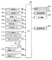
図8を参照して、本実施の形態に係る制御装置のECU900が実行するプログラムの制御構造について説明する。なお、ECU900により実行されるプログラムをCD(Compact Disc)、DVD(Digital Versatile Disc)などの記録媒体に記録して市場に流通させてもよい。
With reference to FIG. 8, a control structure of a program executed by
ステップ(以下、ステップをSと略す)100にて、ECU900は、油温センサ912から送信された信号に基づいて油温THOを検出する。
In step (hereinafter, step is abbreviated as S) 100,
S102にて、ECU900は、車速Vおよびアクセル開度ACCをパラメータに有するマップに基づいて、プライマリプーリ回転数NINの目標回転数を設定する。
In S102,
S104にて、ECU900は、油温THOがしきい値より高いか否かを判断する。油温THOがしきい値より高いと(S104にてYES)、処理はS106に移される。もしそうでないと(S104にてNO)、処理はS114に移される。
In S104,
S106にて、ECU900は、セカンダリプーリ回転数センサ924から送信される信号に基づいてセカンダリプーリ回転数NOUTを検出する。S108にて、ECU900は、セカンダリプーリ回転数NOUTに応じて、目標回転数の上限値を設定する。本実施の形態においては、セカンダリプーリ回転数NOUTが高いほど、上限値がより低くなるように設定される。
In S106,
S110にて、ECU900は、マップを用いて設定された目標回転数が上限値よりも大きいか否かを判断する。マップを用いて設定された目標回転数が上限値よりも大きいと(S110にてYES)、処理はS112に移される。もしそうでないと(S110にてNO)、処理はS114に移される。S112にて、ECU900は、上限値を目標回転数に設定する。
In S110,
S114にて、ECU900は、プライマリプーリ回転数NINが目標回転数になるよ
うに制御する。
In S114,
以上のような構造およびフローチャートに基づく、本実施の形態に係る制御装置の動作について説明する。 An operation of the control device according to the present embodiment based on the above-described structure and flowchart will be described.
車両の走行中、油温センサ912から送信された信号に基づいて油温THOが検出される(S100)。さらに、車速Vおよびアクセル開度ACCをパラメータに有するマップに基づいて、プライマリプーリ回転数NINの目標回転数が設定される(S102)。 While the vehicle is traveling, the oil temperature THO is detected based on the signal transmitted from the oil temperature sensor 912 (S100). Further, based on a map having the vehicle speed V and the accelerator opening ACC as parameters, a target rotational speed of the primary pulley rotational speed NIN is set (S102).
油温THOがしきい値より高いと(S104にてYES)、セカンダリプーリ回転数NOUTが検出され(S106)、セカンダリプーリ回転数NOUTに応じて、プライマリプーリ回転数NINの目標回転数の上限値が設定される(S108)。セカンダリプーリ回転数NOUTが高いほど、上限値がより低くなるように設定される。 If oil temperature THO is higher than the threshold value (YES in S104), secondary pulley rotation speed NOUT is detected (S106), and upper limit value of the target rotation speed of primary pulley rotation speed NIN is determined according to secondary pulley rotation speed NOUT. Is set (S108). The upper limit value is set lower as the secondary pulley rotation speed NOUT is higher.
マップを用いて設定された目標回転数が上限値以下であると(S110にてNO)、プライマリプーリ回転数NINがマップを用いて設定された目標回転数になるように制御される(S114)。 If the target rotational speed set using the map is equal to or lower than the upper limit value (NO in S110), control is performed so that primary pulley rotational speed NIN becomes the target rotational speed set using the map (S114). .
一方、マップを用いて設定された目標回転数が上限値よりも大きいと(S110にてYES)、上限値が目標回転数に設定され(S112)、プライマリプーリ回転数NINが目標回転数になるように制御される(S114)。すなわち、プライマリプーリ回転数NINが上限値になるように制御される。 On the other hand, if the target rotational speed set using the map is larger than the upper limit value (YES in S110), the upper limit value is set to the target rotational speed (S112), and primary pulley rotational speed NIN becomes the target rotational speed. Control is performed as described above (S114). That is, the primary pulley rotation speed NIN is controlled to be the upper limit value.
これにより、無段変速機500の発熱量に影響を与えるセカンダリプーリ回転数NOUTに応じて、プライマリプーリ回転数NINを制御することができる。本実施の形態においては、セカンダリプーリ回転数NOUTが高いために無段変速機500の発熱量が大きくなり易い運転状態では、たとえばアップアップシフトすることによりプライマリプーリ回転数NINを低下して、発熱量を制限することができる。そのため、無段変速機500の作動に用いられる作動油の温度を適正な状態に維持することができる。
Thereby, primary pulley rotation speed NIN can be controlled according to secondary pulley rotation speed NOUT that affects the heat generation amount of continuously
今回開示された実施の形態は、すべての点で例示であって制限的なものではないと考えられるべきである。本発明の範囲は上記した説明ではなくて特許請求の範囲によって示され、特許請求の範囲と均等の意味および範囲内でのすべての変更が含まれることが意図される。 The embodiment disclosed this time should be considered as illustrative in all points and not restrictive. The scope of the present invention is defined by the terms of the claims, rather than the description above, and is intended to include any modifications within the scope and meaning equivalent to the terms of the claims.
100 駆動装置、200 エンジン、300 トルクコンバータ、310 オイルポンプ、400 前後進切換装置、402 サンギヤ、404 キャリア、406 フォワードクラッチ、408 リングギヤ、410 リバースブレーキ、500 ベルト式無段
変速機、502 入力軸、504 プライマリプーリ、506 出力軸、508 セカンダリプーリ、510 伝動ベルト、600 減速歯車、700 差動歯車装置、800 駆動輪、900 ECU、902 エンジン回転数センサ、904 タービン回転数センサ、906 車速センサ、908 スロットル開度センサ、910 冷却水温センサ、912 油温センサ、914 アクセル開度センサ、916 フットブレーキスイッチ、918 ポジションセンサ、920 シフトレバー、922 プライマリプーリ回転数センサ、924 セカンダリプーリ回転数センサ、930 設定部、932 制御部、1000 電子スロットルバルブ、1100 燃料噴射装置、1200 点火装置、2000 油圧制御回路、2002 ライン圧油路、2100 プライマリレギュレータバルブ、2200 SLTリニアソレノイドバルブ、2210 SLSリニアソレノイドバルブ、2310 モジュレータバルブ(1)、2330 モジュレータバルブ(3)、2340 モジュレータバルブ(4)、2312 プレッシャセンサ、2400 コントロールバルブ、2510 変速制御用デューティソレノイド(1)、2520 変速制御用デューティソレノイド(2)、2600 マニュアルバルブ、2710 レシオコントロールバルブ(1)、2720 レシオコントロールバルブ(2)、2800 バイパスコントロールバルブ。
100 driving device, 200 engine, 300 torque converter, 310 oil pump, 400 forward / reverse switching device, 402 sun gear, 404 carrier, 406 forward clutch, 408 ring gear, 410 reverse brake, 500 belt type continuously variable transmission, 502 input shaft, 504 Primary pulley, 506 Output shaft, 508 Secondary pulley, 510 Transmission belt, 600 Reduction gear, 700 Differential gear device, 800 Drive wheel, 900 ECU, 902 Engine speed sensor, 904 Turbine speed sensor, 906 Vehicle speed sensor, 908 Throttle opening sensor, 910 Cooling water temperature sensor, 912 Oil temperature sensor, 914 Accelerator opening sensor, 916 Foot brake switch, 918 Position sensor, 920 Shift lever, 922 Primary pulley Rotational speed sensor, 924 Secondary pulley rotational speed sensor, 930 setting unit, 932 control unit, 1000 electronic throttle valve, 1100 fuel injection device, 1200 ignition device, 2000 hydraulic control circuit, 2002 line pressure oil path, 2100 primary regulator valve, 2200 SLT linear solenoid valve, 2210 SLS linear solenoid valve, 2310 modulator valve (1), 2330 modulator valve (3), 2340 modulator valve (4), 2312 pressure sensor, 2400 control valve, 2510 duty control duty solenoid (1), 2520 Duty solenoid for shift control (2), 2600 Manual valve, 2710 Ratio control valve (1), 2720 Ratio control valve 2), 2800 bypass control valve.
Claims (3)
前記無段変速機の出力軸回転数を検出するための手段と、
前記無段変速機の目標入力軸回転数の上限値を、前記無段変速機の出力軸回転数に応じて設定するための設定手段と、
前記上限値以下になるように前記目標入力軸回転数を設定するための手段と、
前記無段変速機の入力軸回転数が前記目標入力軸回転数になるように制御するための制御手段とを備える、無段変速機の制御装置。 A control device for a continuously variable transmission,
Means for detecting the output shaft speed of the continuously variable transmission;
Setting means for setting an upper limit value of the target input shaft rotational speed of the continuously variable transmission according to the output shaft rotational speed of the continuously variable transmission;
Means for setting the target input shaft rotational speed to be equal to or less than the upper limit;
And a control means for controlling the input shaft rotation speed of the continuously variable transmission to be the target input shaft rotation speed.
前記設定手段は、前記作動油の温度がしきい値よりも高い場合、前記上限値を前記出力軸回転数に応じて設定するため手段を含む、請求項1または2に記載の無段変速機の制御装置。 Means for detecting the temperature of hydraulic oil supplied to the continuously variable transmission;
The continuously variable transmission according to claim 1 or 2, wherein the setting means includes means for setting the upper limit value in accordance with the output shaft rotational speed when the temperature of the hydraulic oil is higher than a threshold value. Control device.
Priority Applications (2)
| Application Number | Priority Date | Filing Date | Title |
|---|---|---|---|
| JP2008081318A JP2009236182A (en) | 2008-03-26 | 2008-03-26 | Control device for continuously variable transmission |
| US12/363,075 US20090248262A1 (en) | 2008-03-26 | 2009-01-30 | Control device and control method for continuously variable transmission |
Applications Claiming Priority (1)
| Application Number | Priority Date | Filing Date | Title |
|---|---|---|---|
| JP2008081318A JP2009236182A (en) | 2008-03-26 | 2008-03-26 | Control device for continuously variable transmission |
Publications (1)
| Publication Number | Publication Date |
|---|---|
| JP2009236182A true JP2009236182A (en) | 2009-10-15 |
Family
ID=41118393
Family Applications (1)
| Application Number | Title | Priority Date | Filing Date |
|---|---|---|---|
| JP2008081318A Pending JP2009236182A (en) | 2008-03-26 | 2008-03-26 | Control device for continuously variable transmission |
Country Status (2)
| Country | Link |
|---|---|
| US (1) | US20090248262A1 (en) |
| JP (1) | JP2009236182A (en) |
Cited By (1)
| Publication number | Priority date | Publication date | Assignee | Title |
|---|---|---|---|---|
| JP2011190873A (en) * | 2010-03-15 | 2011-09-29 | Toyota Motor Corp | Control device of power train |
Families Citing this family (1)
| Publication number | Priority date | Publication date | Assignee | Title |
|---|---|---|---|---|
| JP6070623B2 (en) * | 2014-04-25 | 2017-02-01 | トヨタ自動車株式会社 | Vehicle control device |
Citations (8)
| Publication number | Priority date | Publication date | Assignee | Title |
|---|---|---|---|---|
| JPS62286847A (en) * | 1986-06-03 | 1987-12-12 | Toyota Motor Corp | Control for continuously variable transmission for vehicle |
| JPS6364836A (en) * | 1986-09-04 | 1988-03-23 | Daihatsu Motor Co Ltd | Speed change controlling method for v-belt type continuously variable transmission |
| JPH03292448A (en) * | 1990-04-06 | 1991-12-24 | Toyota Motor Corp | Gear ratio controller of continuously variable transmission for vehicle |
| JPH09133208A (en) * | 1995-11-07 | 1997-05-20 | Mazda Motor Corp | Shift controller in automatic transmission |
| JP2000309236A (en) * | 1999-04-26 | 2000-11-07 | Toyota Motor Corp | Driving control device for vehicle |
| JP2001330115A (en) * | 2000-05-23 | 2001-11-30 | Toyota Motor Corp | Variable speed controller for continuously variable transmission |
| JP2002013626A (en) * | 2000-06-29 | 2002-01-18 | Mazda Motor Corp | Controller of power train |
| JP2003083434A (en) * | 2001-09-07 | 2003-03-19 | Fuji Heavy Ind Ltd | Controller for continuously variable transmission |
-
2008
- 2008-03-26 JP JP2008081318A patent/JP2009236182A/en active Pending
-
2009
- 2009-01-30 US US12/363,075 patent/US20090248262A1/en not_active Abandoned
Patent Citations (8)
| Publication number | Priority date | Publication date | Assignee | Title |
|---|---|---|---|---|
| JPS62286847A (en) * | 1986-06-03 | 1987-12-12 | Toyota Motor Corp | Control for continuously variable transmission for vehicle |
| JPS6364836A (en) * | 1986-09-04 | 1988-03-23 | Daihatsu Motor Co Ltd | Speed change controlling method for v-belt type continuously variable transmission |
| JPH03292448A (en) * | 1990-04-06 | 1991-12-24 | Toyota Motor Corp | Gear ratio controller of continuously variable transmission for vehicle |
| JPH09133208A (en) * | 1995-11-07 | 1997-05-20 | Mazda Motor Corp | Shift controller in automatic transmission |
| JP2000309236A (en) * | 1999-04-26 | 2000-11-07 | Toyota Motor Corp | Driving control device for vehicle |
| JP2001330115A (en) * | 2000-05-23 | 2001-11-30 | Toyota Motor Corp | Variable speed controller for continuously variable transmission |
| JP2002013626A (en) * | 2000-06-29 | 2002-01-18 | Mazda Motor Corp | Controller of power train |
| JP2003083434A (en) * | 2001-09-07 | 2003-03-19 | Fuji Heavy Ind Ltd | Controller for continuously variable transmission |
Cited By (1)
| Publication number | Priority date | Publication date | Assignee | Title |
|---|---|---|---|---|
| JP2011190873A (en) * | 2010-03-15 | 2011-09-29 | Toyota Motor Corp | Control device of power train |
Also Published As
| Publication number | Publication date |
|---|---|
| US20090248262A1 (en) | 2009-10-01 |
Similar Documents
| Publication | Publication Date | Title |
|---|---|---|
| JP4471018B2 (en) | Control device for continuously variable transmission | |
| US7993225B2 (en) | Hydraulic pressure supply unit of continuously variable transmission | |
| JP5435137B2 (en) | Control device for continuously variable transmission for vehicle | |
| JP4363486B2 (en) | Control device and control method for continuously variable transmission | |
| JP4238895B2 (en) | Shift control device for continuously variable transmission for vehicle | |
| JP4238906B2 (en) | Control device for continuously variable transmission, control method, program for realizing the method, and recording medium recording the program | |
| JP5786843B2 (en) | Shift control device for continuously variable transmission | |
| JP4784563B2 (en) | Control device for lock-up clutch | |
| JP4289407B2 (en) | Hydraulic supply device | |
| JP4678036B2 (en) | Control device and control program for continuously variable transmission for vehicle | |
| JP2009264467A (en) | Hydraulic control device | |
| JP4811068B2 (en) | Powertrain control device | |
| JP5458495B2 (en) | Control device for lock-up clutch | |
| JP5447274B2 (en) | Control device for continuously variable transmission for vehicle | |
| JP2007296959A (en) | Control apparatus for vehicle | |
| JP2009236182A (en) | Control device for continuously variable transmission | |
| JP5186938B2 (en) | Control device for continuously variable transmission | |
| JP5374880B2 (en) | Control device for continuously variable transmission | |
| JP4811151B2 (en) | Shift control device for continuously variable transmission for vehicle | |
| JP2008075736A (en) | Shift control device for vehicular continuously variable transmission | |
| JP2006046515A (en) | Hydraulic controller of automatic transmission | |
| JP4678318B2 (en) | Control device for continuously variable transmission | |
| JP2007239981A (en) | Control device of continuously variable transmission | |
| US20100099535A1 (en) | Continuously variable transmission control apparatus | |
| JP5884529B2 (en) | Hydraulic supply device for drivetrain |
Legal Events
| Date | Code | Title | Description |
|---|---|---|---|
| A977 | Report on retrieval |
Free format text: JAPANESE INTERMEDIATE CODE: A971007 Effective date: 20091218 |
|
| A131 | Notification of reasons for refusal |
Free format text: JAPANESE INTERMEDIATE CODE: A131 Effective date: 20100119 |
|
| A02 | Decision of refusal |
Free format text: JAPANESE INTERMEDIATE CODE: A02 Effective date: 20100601 |