JP2009214192A - Fluid injection device - Google Patents
Fluid injection device Download PDFInfo
- Publication number
- JP2009214192A JP2009214192A JP2008057410A JP2008057410A JP2009214192A JP 2009214192 A JP2009214192 A JP 2009214192A JP 2008057410 A JP2008057410 A JP 2008057410A JP 2008057410 A JP2008057410 A JP 2008057410A JP 2009214192 A JP2009214192 A JP 2009214192A
- Authority
- JP
- Japan
- Prior art keywords
- fluid
- variable volume
- chambers
- ejecting apparatus
- ejection device
- Prior art date
- Legal status (The legal status is an assumption and is not a legal conclusion. Google has not performed a legal analysis and makes no representation as to the accuracy of the status listed.)
- Withdrawn
Links
Images


Classifications
-
- A—HUMAN NECESSITIES
- A61—MEDICAL OR VETERINARY SCIENCE; HYGIENE
- A61B—DIAGNOSIS; SURGERY; IDENTIFICATION
- A61B17/00—Surgical instruments, devices or methods, e.g. tourniquets
- A61B17/32—Surgical cutting instruments
- A61B17/3203—Fluid jet cutting instruments
Abstract
Description
本発明は、複数の容積可変チャンバと、複数の容積可変チャンバそれぞれに連通する流体噴射開口部を有する流体噴射装置に関する。 The present invention relates to a fluid ejecting apparatus having a plurality of variable volume chambers and a fluid ejecting opening communicating with each of the plurality of variable volume chambers.
噴射される流体による手術は、血管等の脈管構造を保存しながら臓器実質を切開することが可能であり、さらに、切開部以外の生体組織に与える付随的損傷が軽微であることから患者負担が小さく、また、出血が少ないため出血が術野の視界を妨げないことから迅速な手術が可能であり、特に微小血管からの出血に難渋する肝切除等に多く臨床応用されている。 Surgery with the ejected fluid allows the incision of the organ parenchyma while preserving the vasculature such as blood vessels, and the incidental damage to living tissue other than the incision is minimal, resulting in a burden on the patient. In addition, since the bleeding is small and bleeding does not interfere with the field of view of the operative field, rapid surgery is possible.
このような噴射される流体による手術装置として、基端部に一つの開口部を有し、この開口部と対向する蒸気発生手段を有する液体チャンバを含み、液体チャンバは作動時にマイクロ液体ジェットを発生させるというマイクロ液体ジェット発生装置が知られている(例えば、特許文献1参照)。 Such a surgical device using a fluid to be ejected includes a liquid chamber having one opening at the proximal end and a vapor generating means facing the opening, and the liquid chamber generates a micro liquid jet during operation. There is known a micro liquid jet generating apparatus that causes the liquid to generate (see, for example, Patent Document 1).
また、高圧流体を通す流路を備え、先端部の流路断面形状を扁平にした噴射ノズルを有したウォータジェットカテーテルを備えたウォータジェット手術装置というものが知られている(例えば、特許文献2参照)。 Further, there is known a water jet surgical apparatus including a water jet catheter having a flow path for passing a high-pressure fluid and having a jet nozzle having a flat flow path cross-sectional shape at the tip (for example, Patent Document 2). reference).
さらに、高圧流体を通す流路を備え、先端部に噴射ノズルを有したウォータジェットカテーテルと、このウォータジェットカテーテルとは別体で併設され先端部に吸引口を有すると共に、この吸引口を噴射ノズルと同位置か、前方に位置させた排液吸引用カテーテルとを備えたウォータジェット手術装置というものも知られている(例えば、特許文献3参照)。 Furthermore, a water jet catheter having a flow path for passing a high-pressure fluid and having an injection nozzle at the tip, and a suction port at the tip that is provided separately from the water jet catheter, and this suction port is used as an injection nozzle There is also known a water jet surgical apparatus including a drainage suction catheter that is placed in the same position and positioned forward (see, for example, Patent Document 3).
このような特許文献1から特許文献3では共に、流体を噴射するノズルが、高速流体発生装置に対して一つ設けられており、切除能力を高めるためには噴射速度を高めると共に噴射量を増加させる。しかしながら、このようにすれば、水流が生体組織に深く入り込みすぎるということが考えられる。
In both
このような課題を解決するために、特許文献2に記載のように噴射ノズルの先端を扁平にすることが提案されているが、噴射ノズルを扁平にすることで、噴射面積が広くなり、十分な切除圧力が得られにくいという課題が生じる。 In order to solve such a problem, it has been proposed to flatten the tip of the injection nozzle as described in Patent Document 2, but by flattening the injection nozzle, the injection area becomes large and sufficient. The problem that it is difficult to obtain a sufficient excision pressure arises.
また、特許文献3によれば、噴射ノズルを有するウォータジェットカテーテルとは別体の排液吸引用カテーテルを併設している。このような構成では、液体噴射(切除)と排液吸引とが同時に可能となるが、装置が大きくなり、微細な間隙の手術や、血管等の細管内に装置を挿入することは困難である。 According to Patent Document 3, a drainage suction catheter separate from a water jet catheter having an injection nozzle is also provided. In such a configuration, liquid injection (resection) and drainage suction can be performed at the same time, but the apparatus becomes large, and it is difficult to perform operations on a minute gap or insert the apparatus into a thin tube such as a blood vessel. .
本発明は、上述の課題の少なくとも一部を解決するためになされたものであり、以下の形態または適用例として実現することが可能である。 SUMMARY An advantage of some aspects of the invention is to solve at least a part of the problems described above, and the invention can be implemented as the following forms or application examples.
[適用例1]本適用例に係る流体噴射装置は、外周面に複数の凹部が穿設された柱状の基体と、複数の前記凹部それぞれを封止するダイアフラムと前記凹部と前記ダイアフラムによってそれぞれ形成される複数の流体室とからなる複数の容積可変チャンバと、前記ダイアフラムの変位方向に略平行な複数の前記流体室それぞれの側壁に連通する出口流路と、前記出口流路の先端部に設けられる流体噴射開口部と、複数の前記流体室それぞれに連通する入口流路と、前記入口流路に連通する流体供給チューブと、が備えられ、前記流体室の容積を前記ダイアフラムにより縮小して前記流体噴射開口部から流体をパルス状に噴射することを特徴とする。 Application Example 1 A fluid ejection device according to this application example is formed by a columnar base body having a plurality of recesses formed on the outer peripheral surface, a diaphragm for sealing each of the plurality of recesses, the recess, and the diaphragm. A plurality of variable volume chambers composed of a plurality of fluid chambers, an outlet channel communicating with the side walls of each of the plurality of fluid chambers substantially parallel to the direction of displacement of the diaphragm, and a tip of the outlet channel. A fluid ejection opening, an inlet channel communicating with each of the plurality of fluid chambers, and a fluid supply tube communicating with the inlet channel, the volume of the fluid chamber being reduced by the diaphragm, and The fluid is ejected in pulses from the fluid ejection opening.
本適用例によれば、複数の容積可変チャンバそれぞれに出口流路及び流体噴射開口部を設けていることから、各容積可変チャンバそれぞれにおいてダイアフラムによる容積縮小率を設定することにより、術部硬度に適切な流体の噴射速度、噴射量を得ることができる。 According to this application example, each of the plurality of variable volume chambers is provided with an outlet flow path and a fluid ejection opening. Therefore, by setting a volume reduction rate by a diaphragm in each of the variable volume chambers, the surgical section hardness can be reduced. An appropriate fluid ejection speed and ejection amount can be obtained.
また、上述したように、流体噴射開口部一つ一つを適切な設定としながら、複数の流体噴射開口部から流体を噴射できるので、流体噴射装置全体として流体噴射量を多くして、切除能力を高めることができる。 In addition, as described above, fluid can be ejected from a plurality of fluid ejection openings while appropriately setting each fluid ejection opening, so that the amount of fluid ejection can be increased as a whole fluid ejection device, and the resecting capability can be increased. Can be increased.
[適用例2]上記適用例に係る流体噴射装置において、複数の前記容積可変チャンバそれぞれが、前記基体の外周側面の周方向に離間して配設されていることが好ましい。 Application Example 2 In the fluid ejecting apparatus according to the application example described above, it is preferable that each of the plurality of variable volume chambers be spaced apart in the circumferential direction of the outer peripheral side surface of the base.
このような構成によれば、複数の容積可変チャンバを柱状の基体の外周側面の周方向に穿設される凹部内に配設しているため、突出部がない細い流体噴射部を構成することができ、微細な間隙の手術や、血管等の細管内に装置を挿入することが可能な流体噴射装置を実現できる。 According to such a configuration, since the plurality of variable volume chambers are disposed in the recesses formed in the circumferential direction of the outer peripheral side surface of the columnar base body, a thin fluid ejecting unit having no protrusion is configured. Therefore, it is possible to realize a fluid ejecting apparatus capable of performing operations on a minute gap and inserting the apparatus into a thin tube such as a blood vessel.
[適用例3]上記適用例に係る流体噴射装置において、複数の前記容積可変チャンバそれぞれが、平面方向に併設されていることが望ましい。 Application Example 3 In the fluid ejecting apparatus according to the application example described above, it is preferable that each of the plurality of variable volume chambers be provided side by side in the planar direction.
このような構成の流体噴射装置は扁平形状となるが複数の流体噴射開口部を有していることから、前述した特許文献2のような単純に噴射ノズルを扁平にすることで、噴射面積が広くなり、十分な切除圧力が得られにくいという課題を解決できる。また、複数の流体開口部それぞれから流体を高速で噴射できるので長い術線の切除を可能にし、このことにより、切開手術以外の剥離切除が可能となる効果がある。 Since the fluid ejecting apparatus having such a configuration has a flat shape but has a plurality of fluid ejecting openings, by simply flattening the ejecting nozzle as in Patent Document 2 described above, the ejecting area can be reduced. The problem of widening and difficulty in obtaining sufficient excision pressure can be solved. Further, since the fluid can be ejected from each of the plurality of fluid openings at a high speed, it is possible to excise a long surgical line, thereby having an effect of enabling exfoliation other than an open operation.
[適用例4]上記適用例に係る流体噴射装置において、複数の前記入口流路それぞれに連通する前記流体供給チューブが備えられていることが好ましい。 Application Example 4 In the fluid ejecting apparatus according to the application example, it is preferable that the fluid supply tube communicating with each of the plurality of inlet flow paths is provided.
このような構成によれば、容積可変チャンバと、内部に設けられる流体室と、出口流路(流体噴射開口部)と、入口流路と、流体供給チューブとが専用対応となり、複数の容積可変チャンバ間の流体噴射速度、噴射量を個々に設定可能になる他、ばらつきを減縮することができる。 According to such a configuration, the variable volume chamber, the fluid chamber provided in the interior, the outlet flow path (fluid ejection opening), the inlet flow path, and the fluid supply tube are dedicated, and a plurality of variable volumes are available. In addition to being able to individually set the fluid ejection speed and ejection amount between the chambers, variations can be reduced.
[適用例5]上記適用例に係る流体噴射装置において、前記基体の外周部に嵌着されると共に、前記流体供給チューブを内包する外郭チューブが、さらに備えられていることが好ましい。 Application Example 5 In the fluid ejecting apparatus according to the application example described above, it is preferable that an outer tube that is fitted to the outer peripheral portion of the base body and that includes the fluid supply tube is further provided.
複数の入口流路それぞれに流体供給チューブを連通させる場合、流体噴射部の外周と流体チューブそれぞれの外周との間には段差ができることになる。そこで、これら流体供給チューブを内包するような外郭チューブを設けることにより、流体噴射部と外郭チューブの外周を概ね同じ外径とすれば上記段差を解消し、血管等の細間に流体噴射部を挿入または引き抜きを容易にし、組織を傷つけることを防止することができる。 When the fluid supply tube is communicated with each of the plurality of inlet flow paths, a step is formed between the outer periphery of the fluid ejecting unit and the outer periphery of each of the fluid tubes. Therefore, by providing an outer tube that encloses these fluid supply tubes, if the outer circumferences of the fluid ejecting portion and the outer tube have substantially the same outer diameter, the above step is eliminated, and the fluid ejecting portion is provided between the blood vessels and the like. Insertion or withdrawal can be facilitated and damage to the tissue can be prevented.
また、各流体供給チューブが非常に細く強度が十分とはいえない場合があるが、外郭チューブを設けることにより、流体供給チューブを保護することができ、取り扱いが容易となる。 In addition, each fluid supply tube may be very thin and may not have sufficient strength. However, by providing an outer tube, the fluid supply tube can be protected and easy to handle.
[適用例6]上記適用例に係る流体噴射装置において、前記流体供給チューブが、複数の前記入口流路に連通すると共に、複数の前記容積可変チャンバを密閉するように前記基体の外周部に嵌着されていることが好ましい。 Application Example 6 In the fluid ejecting apparatus according to the application example described above, the fluid supply tube communicates with the plurality of inlet flow paths and is fitted to the outer peripheral portion of the base so as to seal the plurality of variable volume chambers. Preferably it is worn.
上述したように、容積可変チャンバは、基体の外周部に穿設された凹部内に配設される。流体供給チューブで容積可変チャンバを密閉することにより、液体を含む環境下において、容積可変チャンバに液体が付着することによるダイアフラムの駆動を妨げることを防止することができる。 As described above, the variable volume chamber is disposed in a recess formed in the outer peripheral portion of the base. By sealing the variable volume chamber with the fluid supply tube, it is possible to prevent the diaphragm from being obstructed by the liquid adhering to the variable volume chamber in an environment containing liquid.
また、このような構成にすれば、複数の入口流路への流体供給と、容積可変チャンバの密閉と、を一つの流体供給チューブで行い、構造を簡素化することができる。
さらに、基体及び容積可変チャンバを含む流体噴射部が流体供給チューブ内に収納されることになり、流体噴射部を流体供給チューブの延長範囲に存在させることができるので、血管等の脈管構造に挿入しやすくなるという効果がある。
Further, with such a configuration, it is possible to simplify the structure by supplying fluid to the plurality of inlet channels and sealing the variable volume chamber with a single fluid supply tube.
Further, the fluid ejecting unit including the base body and the variable volume chamber is accommodated in the fluid supply tube, and the fluid ejecting unit can be present in the extension range of the fluid supply tube. There is an effect that it becomes easy to insert.
[適用例7]上記適用例に係る流体噴射装置において、複数の前記流体室に対して共通の入口流路と、前記入口流路から分岐され、複数の前記流体室それぞれに連通される接続流路が設けられていることが好ましい。 Application Example 7 In the fluid ejecting apparatus according to the application example described above, a common inlet channel for the plurality of fluid chambers, and a connection flow branched from the inlet channel and communicated with each of the plurality of fluid chambers It is preferable that a path is provided.
複数の容積可変チャンバを備え、これらに連通する入口流路に対応する液体供給チューブの数が増加する場合、流体供給チューブが互いに干渉して基体の外径(つまり、流体噴射部の外径)が大きくなってしまう。しかし、上述した適用例4による構成では、入口流路及び流体供給チューブを1本とし、基体内部において1本の入口流路から複数の流体室それぞれに連通する接続流路に分岐すれば小径の流体噴射部を実現できる。 When the number of liquid supply tubes corresponding to the inlet flow passages provided with a plurality of variable volume chambers and communicating with these increases, the fluid supply tubes interfere with each other to cause the outer diameter of the substrate (that is, the outer diameter of the fluid ejecting portion) Will become bigger. However, in the configuration according to the application example 4 described above, if a single inlet channel and a fluid supply tube are provided, and the inside of the base is branched from a single inlet channel to a connection channel communicating with each of a plurality of fluid chambers, a small diameter is provided. A fluid ejecting unit can be realized.
[適用例8]上記適用例に係る流体噴射装置において、前記基体の先端部に突設された複数の突起部に、複数の前記出口流路それぞれが連通されていることが好ましい。 Application Example 8 In the fluid ejecting apparatus according to the application example described above, it is preferable that each of the plurality of outlet channels is communicated with a plurality of protrusions protruding from the tip of the base.
このような構成によれば、複数の出口流路それぞれが基体の先端部に突設される突起部に連通されている。従って、これら突起部に流体噴射開口部が設けられることになり、各流体噴射開口部と術部に対して良好な視界を得ることができる。 According to such a configuration, each of the plurality of outlet channels is communicated with the protrusion that protrudes from the tip of the base. Therefore, the fluid ejection openings are provided in these protrusions, and a good field of view can be obtained for each fluid ejection opening and the surgical site.
[適用例9]上記適用例に係る流体噴射装置において、前記流体供給チューブが、複数の前記入口流路それぞれに連通する複数の流体供給路を有することが好ましい。 Application Example 9 In the fluid ejecting apparatus according to the application example described above, it is preferable that the fluid supply tube has a plurality of fluid supply paths that communicate with the plurality of inlet channels.
このような構成によれば、複数の入口流路それぞれに対応する流体供給路を1本の流体供給チューブに形成することにより、構造を簡素化すると共に、基体の外径(つまり、流体噴射部の外径)を小さくすることができる。 According to such a configuration, the fluid supply path corresponding to each of the plurality of inlet flow paths is formed in one fluid supply tube, whereby the structure is simplified and the outer diameter of the base (that is, the fluid ejecting section) ) Can be reduced.
[適用例10]上記適用例に係る流体噴射装置において、前記入口流路と前記流体供給チューブの流体供給路との間に、流体滞留室が設けられていることが望ましい。 Application Example 10 In the fluid ejecting apparatus according to the application example described above, it is preferable that a fluid retention chamber is provided between the inlet channel and the fluid supply channel of the fluid supply tube.
流体室、入口流路、流体供給路がそのまま直列に連通される場合、パルス状の噴射の間に、流体供給路からの流体圧力により、不要な流体流動が発生することがある。そこで、流体滞留室を設けることにより流体滞留室内に充填されている流体が緩衝部となり、不要な流体流動の発生を抑制することができる。 When the fluid chamber, the inlet channel, and the fluid supply path are communicated in series as they are, unnecessary fluid flow may occur due to the fluid pressure from the fluid supply path during the pulse-like ejection. Therefore, by providing the fluid retention chamber, the fluid filled in the fluid retention chamber becomes a buffer portion, and generation of unnecessary fluid flow can be suppressed.
逆に、パルス状の噴射時には、流体滞留室内に充填されている流体が流体抵抗となり、入口流路から流体が逆流することを抑制することができる。 On the contrary, at the time of pulse-like ejection, the fluid filled in the fluid retention chamber becomes a fluid resistance, and it is possible to prevent the fluid from flowing backward from the inlet channel.
[適用例11]上記適用例に係る流体噴射装置において、前記基体の先端部から尾部を貫通する吸引流路と、前記吸引流路に連通する吸引チューブが設けられていることが好ましい。 Application Example 11 In the fluid ejecting apparatus according to the application example described above, it is preferable that a suction channel that penetrates from the tip of the base to the tail and a suction tube that communicates with the suction channel are provided.
このような構成によれば、流体噴射開口部からの液体噴射による組織切除と、組織切除による残渣及び排液を吸引流路から吸引することができる。そして、吸引流路を基体内に形成していることから、前述した特許文献3のように、ウォータジェットカテーテルと排液吸引用カテーテルとを併設する構成に比べ小型の流体噴射装置を実現できる。 According to such a configuration, the tissue excision by the liquid ejection from the fluid ejection opening, and the residue and drainage by the tissue excision can be aspirated from the suction channel. Since the suction channel is formed in the substrate, a fluid ejecting apparatus that is smaller than a configuration in which a water jet catheter and a drainage suction catheter are provided together as in Patent Document 3 described above can be realized.
[適用例12]上記適用例に係る流体噴射装置において、前記流体供給チューブと前記吸引チューブとが一体の接続チューブで形成され、複数の前記入口流路に連通する流体供給路と、前記吸引流路に連通する吸引路と、が、前記接続チューブに設けられていることが望ましい。 Application Example 12 In the fluid ejecting apparatus according to the application example described above, the fluid supply tube and the suction tube are formed as an integral connection tube, and a fluid supply path that communicates with the plurality of inlet channels, and the suction flow It is desirable that a suction path communicating with the path is provided in the connection tube.
このような構成によれば、複数の流体供給路と、吸引路と、を1本の接続チューブに形成することにより、複数の流体供給路と吸引流路とを備えていても小径で、構造が簡単な流体噴射装置を実現できる。 According to such a configuration, a plurality of fluid supply paths and a suction path are formed in one connection tube, so that even if a plurality of fluid supply paths and a suction flow path are provided, the structure is small. However, a simple fluid ejecting apparatus can be realized.
[適用例13]上記適用例に係る流体噴射装置において、複数の前記容積可変チャンバそれぞれの駆動タイミングが一致していることが好ましい。 Application Example 13 In the fluid ejection device according to the application example described above, it is preferable that the drive timings of the plurality of variable volume chambers coincide with each other.
備えられる全ての容積可変チャンバの駆動タイミングを一致させることにより、全体としての流体噴射量を増加し、切除能力を高めることができる。 By matching the drive timings of all the variable volume chambers provided, the fluid ejection amount as a whole can be increased and the excision ability can be enhanced.
[適用例14]上記適用例に係る流体噴射装置において、複数の前記容積可変チャンバそれぞれの駆動タイミングをずらしていることが望ましい。 Application Example 14 In the fluid ejecting apparatus according to the application example described above, it is preferable that the drive timing of each of the plurality of variable volume chambers is shifted.
このような構成にすれば、各流体噴射開口部からの流体噴射のタイミングを変えることにより、例えば、前述のタイミングを一致させる場合よりも切除能力が小さくなるので、このような制御を行うことで、弱い切除能力をもつ流体によって切除部を洗浄して視界を確保することが可能になる。 With such a configuration, by changing the timing of fluid ejection from each fluid ejection opening, for example, the excision ability becomes smaller than in the case of matching the above-mentioned timings. The field of view can be secured by cleaning the excision with a fluid having a weak excision ability.
[適用例15]上記適用例に係る流体噴射装置において、複数の前記容積可変チャンバそれぞれから噴射する流体の噴射速度、噴射量が同等であることが望ましい。 Application Example 15 In the fluid ejection device according to the application example described above, it is preferable that the ejection speed and the ejection amount of the fluid ejected from each of the plurality of volume variable chambers are equal.
このような構成では、複数の容積可変チャンバの構成と寸法を同じにし、入力する駆動信号を共通にできるので、駆動信号を生成する駆動制御回路を含めて構造を簡素化することができる。 In such a configuration, the configuration and dimensions of the plurality of variable volume chambers can be made the same and the drive signal to be input can be made common, so that the structure including the drive control circuit that generates the drive signal can be simplified.
[適用例16]上記適用例に係る流体噴射装置において、複数の前記容積可変チャンバのうち、少なくとも一つから噴射する流体の噴射速度、噴射量が、他と異なることが望ましい。 Application Example 16 In the fluid ejection device according to the application example described above, it is preferable that the ejection speed and the ejection amount of the fluid ejected from at least one of the plurality of volume variable chambers are different from the others.
このようにすれば、切除部の硬度や状態に応じて、適切な噴射速度、噴射量を選択して使用することが可能となる。 If it does in this way, according to the hardness and state of an excision part, it will become possible to select and use an appropriate jet speed and jet quantity.
[適用例17]上記適用例に係る流体噴射装置において、複数の前記容積可変チャンバのうちのいくつかを選択的に駆動することが望ましい。 Application Example 17 In the fluid ejecting apparatus according to the application example described above, it is preferable that some of the plurality of variable volume chambers are selectively driven.
このようにすれば、切除部の硬度や範囲に応じて、必要な容積可変チャンバを選択して使用することができる。この際、選択する容積可変チャンバは、一つまたは複数または全部であってもよい。 If it does in this way, according to the hardness and range of an excision part, a required volume variable chamber can be selected and used. In this case, one, a plurality, or all of the variable volume chambers may be selected.
以下、本発明の実施形態を図面に基づいて説明する。
図1〜図6は実施形態1及びその変形例、図7,8は実施形態2、図9は実施形態3、図10は実施形態4、図11,12は実施形態5、図13は実施形態6に係る流体噴射装置を示している。
なお、以下の説明で参照する図は、図示の便宜上、部材ないし部分の縦横の縮尺は実際のものとは異なる模式図である。
また、本発明による流体噴射装置は、インク等を用いた描画、細密な物体及び構造物の洗浄、手術用メス等様々に採用可能である。但し、以下に説明する実施の形態では、血管内に挿入し血栓等を除去する目的で用いるカテーテルの先端に設置することに適した流体噴射装置、あるいは生体組織を切開または切除することに好適な流体噴射装置を例示して説明する。従って、実施の形態にて用いる流体は、水または生理食塩水であり、以降、これら流体を総称して液体と表すことがある。
(実施形態1)
Hereinafter, embodiments of the present invention will be described with reference to the drawings.
1 to 6 are
Note that the drawings referred to in the following description are schematic views in which the vertical and horizontal scales of members or portions are different from actual ones for convenience of illustration.
In addition, the fluid ejecting apparatus according to the present invention can be used in various ways such as drawing using ink, washing fine objects and structures, and a scalpel. However, in the embodiment described below, it is suitable for a fluid ejecting apparatus suitable for installation at the distal end of a catheter used for the purpose of inserting into a blood vessel and removing a thrombus, or for incising or excising a living tissue. A fluid ejecting apparatus will be described as an example. Therefore, the fluid used in the embodiment is water or physiological saline, and hereinafter, these fluids may be collectively referred to as a liquid.
(Embodiment 1)
図1は、実施形態1に係る流体噴射装置の概略構成の一例を示す説明図である。図1において、流体噴射装置100は、基本構成として液体を収容し、その液体を供給する液体供給部としての輸液バッグを含む駆動制御部110と、液体を脈動に変化させる流体噴射部10と、駆動制御部110と流体噴射部10とを連通する液体供給チューブ80と、を備えている。流体噴射部10は、液体を脈動に変化させて複数の液体噴射開口部から液滴200としてパルス状に高速噴射させる。
FIG. 1 is an explanatory diagram illustrating an example of a schematic configuration of the fluid ejecting apparatus according to the first embodiment. In FIG. 1, a
駆動制御部110には、図示しない駆動波形生成回路部と駆動制御回路部とが備えられ、術部の硬度、切除範囲等の条件に対応して駆動波形を調整する調整装置112と、駆動条件等を表示する表示部111が備えられている。
The
次に、図2を参照して本実施形態の流体噴射装置について説明する。
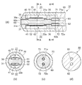
図2は、実施形態1に係る流体噴射部を示し、(a)は液体の流動方向に沿って切断した切断面を示す断面図、(b)は(a)のA−A切断面を示す断面図、(c)は(a)のB−B切断面を示す断面図、(d)は液体供給チューブの断面形状を示している。図2(a)〜(c)において、流体噴射部10は、内部に複数の容積可変チャンバ21,22を備えて構成されている。
Next, the fluid ejecting apparatus of this embodiment will be described with reference to FIG.
2A and 2B show a fluid ejecting unit according to the first embodiment, in which FIG. 2A is a cross-sectional view showing a cut surface cut along a liquid flow direction, and FIG. 2B shows an AA cut surface of FIG. Sectional drawing, (c) is sectional drawing which shows the BB cut surface of (a), (d) has shown the sectional shape of the liquid supply tube. 2A to 2C, the
容積可変チャンバ21,22は、図2(b)に示すように円柱状の基体60の外周部に互いに対向する位置に穿設された凹部内に配設されている。
容積可変チャンバ21は、流体室61の上部開口部の周縁に固定されると共に、流体室61を密閉封止するダイアフラム40と、ダイアフラム40の表面に設けられる圧電素子51とから構成されている。
As shown in FIG. 2B, the
The
一方、容積可変チャンバ22は、流体室62の上部開口部の周縁に固定され、流体室62を密閉封止するダイアフラム41と、ダイアフラム41の表面に設けられる圧電素子52とから構成されている。
従って、容積可変チャンバ21,22共に、基体60の外周部から突出する部位は存在しない。
On the other hand, the
Accordingly, there is no portion protruding from the outer peripheral portion of the
流体室61には、ダイアフラム40の変位方向に略平行な側壁と基体60の先端部60aに連通する出口流路30が形成され、出口流路30の先端部は流体噴射開口部30aである。
In the
また、流体室62には、ダイアフラム41の変位方向に略平行な側壁と基体60の先端部60aに連通する出口流路31が形成され、出口流路31の先端部は流体噴射開口部31aである。
The
出口流路30,31は共に液体の流動方向に垂直な断面積が、流体室61,62の同方向の断面積よりもはるかに小さく設定される。従って、出口流路30と流体噴射開口部30a、出口流路31と流体噴射開口部31aで構成される部位はノズルを構成する。
Both the
出口流路30と対向する位置には入口流路35が形成され、出口流路31と対向する位置には入口流路36が形成されている。入口流路35は流体室61と基体60の尾部60bの間を貫通し、入口流路36は流体室62と基体60の尾部60bの間を貫通している。
An
また、基体60の尾部60bには、接続管71,72が植立されている。接続管71には接続流路71aが開設されており、一部が尾部60bから突出されている。接続流路71aは入口流路35に連通している。なお、接続流路71aの液体流動方向に垂直な断面積は入口流路35の同方向の断面積よりも大きい。接続流路72aは入口流路36に連通している。なお、接続流路72aの液体流動方向に垂直な断面積は入口流路36の同方向の断面積よりも大きい。
Further, connecting
基体60の外周部には蓋筒体70が嵌着されている。蓋筒体70は、基体60のほぼ全長にわたって設けられており、基体60と密着固定される。従って、容積可変チャンバ21,22はそれぞれ、空間21a,22aを有して密閉封止される。空間21a,22aは、ダイアフラム40,41の可動範囲を確保する大きさに設定される。
A
基体60の尾部60bには、液体供給チューブ80が装着される。液体供給チューブ80は、図2(d)に示すように、液体供給路81,82が開設されている。液体供給路81は接続管71に嵌着され、液体供給路82は接続管72に嵌着されている。こうして、流体室61から液体供給路81まで、及び流体室62から液体供給路82までが連通される。
A
液体供給チューブ80は、図1に示す駆動制御部110内の輸液バッグに連通し、輸液バッグから一定の圧力で液体が液体供給路81,82を通って流体室61,62まで供給される。
なお、液体供給チューブ80の外径は、蓋筒体70の外径とほぼ同じであり、流体噴射部10と液体供給チューブ80の外形は連続した形状となる。
The
The outer diameter of the
続いて、図1,2を参照して本実施形態による流体噴射装置100における液体の流動の概要を簡単に説明する。駆動制御部110内部には輸液バッグと、輸液バッグに接続された圧力発生部(共に図示は省略)が内蔵されている。圧力発生部は液体供給チューブ80に液体を送出するように接続されている。輸液バッグに収容されている液体は、圧力発生部によって一定の圧力で液体供給チューブ80(液体供給路81,82)を介して入口流路35,36に供給される。さらに液体は流体室61,62、出口流路30,31を通って流体噴射開口部30a,31aからパルス状に噴射される。
Next, the outline of the flow of the liquid in the
なお、輸液バッグは、駆動制御部110から分離し、流体噴射部10に対して高い位置に配設して、輸液バッグと流体噴射部10との位置水頭の差によって生じる圧力差を利用して流体噴射部10に液体を一定の圧力で流入させる構成としてもよい。
Note that the infusion bag is separated from the
次に、流体噴射部10の動作について説明する。図2を参照して説明する。各容積可変チャンバの個別の基本動作は同じであるので、容積可変チャンバ21を例示して説明する。まず、駆動制御部110に含まれる駆動波形生成回路部によって形成された駆動波形を駆動制御回路部から圧電素子51,52に印加する。
Next, the operation of the
流体室61には、入口流路35から液体が供給される。ここで、圧電素子51に駆動信号が入力され、圧電素子51が充電され急激に圧電素子51が収縮したとすると、ダイアフラム40は流体室61の容積を縮小する方向に急激に凸状に変位する。その結果、流体室61内の圧力は、入口流路35側及び出口流路30側のそれぞれの合成イナータンスL1,L2が十分な大きさを有していれば急速に上昇して数気圧に達する。
The fluid is supplied from the
この圧力は、入口流路35に加えられていた圧力発生部による圧力よりはるかに大きいため、入口流路35側から流体室61内への液体の流入はその圧力によって減少し、出口流路30からの流出は増加する。しかし、入口流路35側の合成イナータンスL1は、出口流路30側の合成イナータンスL2よりも大きいため、入口流路35から流体室61内への液体の流入の減少量より出口流路30からの流出の増加量が大きい。
その結果、出口流路30を通して、流体噴射開口部30aからパルス状の流体吐出、つまり、高速の液滴200がパルス状に噴射される。
Since this pressure is much larger than the pressure generated by the pressure generating unit applied to the
As a result, pulsed fluid ejection, that is, high-
一方、流体室61の容積を縮小した後、駆動電圧の電圧低下に伴い圧電素子51は放電し初期状態に復帰する。流体室61内は、入口流路35側からの液体流入量の減少と出口流路30からの液体流出の増加との相互作用で、圧力上昇後に低圧若しくは真空状態となり、入口流路35から液体が流体室61内に流入する。その後、圧電素子51の収縮があれば、流体噴射開口部30aから高速のパルス状の液滴を継続して噴射することができる。
On the other hand, after the volume of the
容積可変チャンバ22側においても同様な動作を行うので、流体噴射開口部30a,31aから同時に液滴が高速で噴射される。
Since the same operation is performed on the
従って、上述した構成によれば、複数の容積可変チャンバ21,22それぞれに出口流路30,31及び流体噴射開口部30a,31aを設けていることから、各容積可変チャンバそれぞれにおいてダイアフラム40,41による容積縮小率を設定することにより、術部硬度に適切な流体の噴射速度、噴射量を得ることができる。
Therefore, according to the above-described configuration, the
また、流体噴射開口部30a,31aそれぞれの噴射条件を適切な設定としながら、流体噴射開口部30a,31aから同時に流体を噴射できるので、流体噴射装置100(流体噴射部10)全体として流体噴射量を多くして、切除能力を高めることができる。
In addition, since the fluid can be ejected simultaneously from the
また、容積可変チャンバ21,22を柱状の基体60の外周の対向する側面に穿設される凹部内に配設しているため、突出部がない細い流体噴射部10を構成することができ、微細な間隙の手術や、血管等の細管内に装置を挿入することが可能な流体噴射装置を実現できる。
Further, since the
また、液体供給チューブ80が、入口流路35,36それぞれに連通する複数の液体供給路81,82を有していることから、液体供給チューブ80の流体噴射部10への接続構造を簡素化すると共に、基体60の外径(つまり、流体噴射部の外径)を小さくすることができる。
(第1変形例)
In addition, since the
(First modification)
続いて、実施形態1の第1変形例について図面を参照して説明する。第1変形例は、複数の入口流路それぞれに連通する液体供給チューブが備えられていることに特徴を有している。従って、上述した実施形態1との相違個所について説明する。
図3は実施形態1の第1変形例に係る流体噴射部を示す部分断面図である。図3において、入口流路35に連通する接続流路71aを有する接続管71には、液体供給チューブ83が嵌着されている。一方、入口流路36に連通する接続流路72aを有する接続管72には、液体供給チューブ84が嵌着されている。液体供給チューブ83,84は、前述した輸液バッグに接続される。
Then, the 1st modification of
FIG. 3 is a partial cross-sectional view illustrating a fluid ejection unit according to a first modification of the first embodiment. In FIG. 3, a
これら入口流路35,36に対応して設けられる液体供給チューブ83,84の外側には、液体供給チューブ83,84を内包する外郭チューブ90が設けられている。外郭チューブ90は、基体60の尾部60bに嵌着され、液体供給チューブ83,84の全長範囲に設けられることがより好ましい。外郭チューブ90の端部は、蓋筒体70の端部に当接する位置まで挿着され、外径は蓋筒体70の外径とほぼ同等とする。
An
このような構成にすれば、容積可変チャンバ21,22と、内部に設けられる流体室61,62と、出口流路30,31(流体噴射開口部30a,31a)と、入口流路35,36と、液体供給チューブ83,84とがそれぞれ専用の組み合わせとなる。従って、複数の容積可変チャンバ間のばらつきを減縮することができる。また、流体噴射速度、噴射量を個々に設定することができる。
With such a configuration, the
さらに、外郭チューブ90を設け、流体噴射部10の外周(第1変形例では蓋筒体70の外周)と外郭チューブ90の外周を概ね同じ外径とすれば、血管等の細間に流体噴射部を挿入または引き抜きすることを容易にし、挿入、引き抜きにより組織を傷つけることを防止することができる。
Furthermore, if the
また、液体供給チューブ83,84は、非常に細く強度を十分に確保することが困難になる場合があるが、外郭チューブ90を設けることにより、液体供給チューブ83,84を保護することができ、取り扱いが容易となる。
(第2変形例)
Further, the
(Second modification)
続いて、実施形態1の第2変形例について図面を参照して説明する。第2変形例は、流体供給チューブが複数の入口流路に連通すると共に、複数の容積可変チャンバを密閉するように基体の外周部に嵌着されていることを特徴とする。従って、実施形態1との相違個所を中心に説明する。
図4は実施形態1の第2変形例に係る流体噴射部を示す断面図である。図4において、流体噴射部10は、容積可変チャンバ21,22が配設された基体60の外周部に液体供給チューブ80が嵌着されて構成されている。
Then, the 2nd modification of
FIG. 4 is a cross-sectional view illustrating a fluid ejection unit according to a second modification of the first embodiment. In FIG. 4, the
基体60には先端部外周に鍔部60cが設けられている。また、流体室61に連通する入口流路35は尾部60bまで貫通している。一方、流体室62に連通する入口流路36は尾部60bまで貫通している。そして、入口流路35,36の両方が液体供給チューブ80の液体供給路85に連通される。
The
液体供給チューブ80は、端部が基体60の鍔部60cに当接する位置まで挿入され、容積可変チャンバ21,22それぞれの上部を密閉封止している。なお、液体供給チューブ80の外径は、鍔部60cの外径とほぼ一致している。他の構成は前述した実施形態1(図2、参照)と同じである。
The
従って、このような構成にすれば、液体供給チューブ80で容積可変チャンバ21,22を密閉することにより、液体を含む施術環境下において、容積可変チャンバ21,22(具体的には、ダイアフラム40,41及び圧電素子51,52)に液体が付着することによる容積可変チャンバ21,22の駆動を妨げることを防止することができる。
Accordingly, with such a configuration, the
また、このような構成にすれば、複数の入口流路への流体供給と、容積可変チャンバの密閉と、を一つの流体供給チューブで行うことができ、構造を簡素化することができる。 Further, with such a configuration, the fluid supply to the plurality of inlet channels and the sealing of the variable volume chamber can be performed with one fluid supply tube, and the structure can be simplified.
さらに、基体60及び容積可変チャンバ21,22を含む流体噴射部10が液体供給チューブ80内に収納されることになり、流体噴射部10を液体供給チューブ80の延長範囲に存在させることができるので、血管等の脈管構造に挿入しやすくなるという効果がある。
(第3変形例)
Further, the
(Third Modification)
続いて、実施形態1の第3変形例について図面を参照して説明する。第3変形例は、基体の先端部に突設された突起部に、複数の出口流路それぞれが連通されていることを特徴とする。従って、実施形態1との相違個所を中心に説明する。
図5は、実施形態1の第3変形例に係る流体噴射部を示す断面図である。図5において、流体噴射部10は、流体室61,62それぞれに連通された出口流路30,31を有している。
Then, the 3rd modification of
FIG. 5 is a cross-sectional view illustrating a fluid ejection unit according to a third modification of the first embodiment. In FIG. 5, the
基体60の先端部60aには突起部としての吐出管75,76が植立されている。吐出管75には出口流路30に連通する流路75aが開設され、吐出管76には出口流路31に連通する流路76aが開設されている。流路75a,76aそれぞれの液体流動方向に垂直な断面積は、出口流路30,31それぞれの断面積と同じか、僅かに縮小されていることが望ましい。また、流路75a,76aの先端部には、液体噴射開口部が形成される。
なお、吐出管75,76に対して、基体60から類似形状の突起部を基体60と一体で形成する構成としてもよい。
また、液体供給チューブと入口流路との接続構造は、前述した第1変形例(図3、参照)または第2変形例(図4、参照)に記載の構造を適合できる。
In addition, it is good also as a structure which forms the projection part of a similar shape from the base |
In addition, the connection structure between the liquid supply tube and the inlet channel can be adapted to the structure described in the first modification (see FIG. 3) or the second modification (see FIG. 4).
従って、このような構成によれば、出口流路30,31それぞれが基体60の先端部に突設される突起部としての吐出管75,76に連通されている。これら突起部それぞれに流体噴射開口部が設けられることになり、各流体噴射開口部と術部に対して良好な視界を得ることができる。
(第4変形例)
Therefore, according to such a configuration, each of the
(Fourth modification)
続いて、実施形態1の第4変形例について図面を参照して説明する。第4変形例は、複数の流体室に流体を供給する共通の入口流路と、この入口流路から分岐され、流体室それぞれに連通される接続流路が設けられていることを特徴とする。従って、実施形態1との相違個所を中心に説明する。
図6は、実施形態1の第4変形例に係る流体噴射部を示す断面図であり、(a)は液体の流動方向に沿って切断した断面図、(b)は(a)のC−C切断面を示す断面図である。図6(a),(b)において、流体噴射部10は、流体室61,62に対して共通の1本の入口流路65が設けられている。入口流路65は、基体60の断面方向の略中央部に設けられ、一方の端部は流体室61,62の底部に達する位置まで延在され、他方の端部は尾部60bを貫通している。
Then, the 4th modification of
6A and 6B are cross-sectional views illustrating a fluid ejecting unit according to a fourth modification of the first embodiment, in which FIG. 6A is a cross-sectional view taken along the flow direction of the liquid, and FIG. It is sectional drawing which shows C cut surface. 6 (a) and 6 (b), the
入口流路65からは、流体室61に連通する接続流路66と、流体室62に連通する接続流路67と、が分岐されて形成されている。ここで、入口流路65は、流体室61,62に対して十分な液体供給が可能な断面積を有している。また、入口流路65と接続流路66または接続流路67の合成イナータンスが入口流路側の合成イナータンスL1であって、出口流路30または出口流路31それぞれの合成イナータンスL2よりも大きくなるように、入口流路65及び接続流路66,67の断面積、流路長さが設定されている。
A
また、液体供給チューブ80は、前述した第2変形例(図4、参照)と同様に、端部が基体60の鍔部60cに当接する位置まで挿入され、基体60の外周部に嵌着されると共に容積可変チャンバ21,22それぞれの上部を密閉封止している。
In addition, the
なお、容積可変チャンバ21,22の密閉は、前述した第1変形例(図3、参照)と同様に蓋筒体70にて行い、液体供給チューブ80を基体60の尾部60bの付近の外周部に嵌着させる構造としてもよい。
The
また、図示は省略するが、入口流路65に連通する液体チューブ嵌着部を尾部60bから突設させ、この液体チューブ嵌着部に液体供給チューブ80を嵌着接続する構造としてもよい。その際、第1変形例(図3、参照)と同様に、液体供給チューブ80を内包する外郭チューブ90を設ける構造とすることがより好ましい。
Although not shown, a liquid tube fitting portion that communicates with the
複数の容積可変チャンバを備え、これらに連通する入口流路に対応する液体供給チューブの数が増加する場合、液体供給チューブが互いに干渉して基体60の外径(つまり、流体噴射部10の外径)が大きくなってしまう。しかし、上述した第4変形例による構成では、入口流路65及び液体供給チューブ80を1本とし、基体60内部において1本の入口流路65から接続流路66,67に分岐すれば小径の流体噴射部10を実現できる。
(実施形態2)
When the number of liquid supply tubes corresponding to the inlet flow passages provided with a plurality of variable volume chambers and communicating with these chambers increases, the liquid supply tubes interfere with each other to cause the outer diameter of the base body 60 (that is, outside the fluid ejecting unit 10 (Diameter) becomes large. However, in the configuration according to the above-described fourth modified example, if the
(Embodiment 2)
続いて、実施形態2に係る液体噴射装置について図面を参照して説明する。実施形態2は、入口流路と液体供給チューブの液体供給路との間に、液体滞留室が設けられていることを特徴としている。従って、前述した実施形態1(図2、参照)との相違個所を中心に説明する。
図7は、実施形態2に係る流体噴射部を示す断面図であり、(a)は液体の流動方向に沿って切断した部分断面図、(b)は(a)のD−D切断面を示す断面図である。図7(a),(b)において、流体噴射部10は、基体60の尾部60bに接続管95が嵌着され、この接続管95に液体供給チューブ80が嵌着されて構成されている。
Next, the liquid ejecting apparatus according to the second embodiment will be described with reference to the drawings. Embodiment 2 is characterized in that a liquid retention chamber is provided between the inlet flow path and the liquid supply path of the liquid supply tube. Therefore, the description will focus on the differences from the first embodiment (see FIG. 2).
7A and 7B are cross-sectional views illustrating the fluid ejecting unit according to the second embodiment. FIG. 7A is a partial cross-sectional view taken along the flow direction of the liquid, and FIG. It is sectional drawing shown. 7A and 7B, the
接続管95は基体60側に入口流路35,36の両方に連通し、入口流路35,36の容積よりもはるかに大きい容積を有する液体滞留室96が設けられている。接続管95には、液体滞留室96と液体供給チューブ80とを連通する接続開口部95aがさらに備えられている。なお、接続開口部95aの液体流動方向に垂直な断面積は、入口流路35,36の総断面積よりも大きい。
The connecting
また、液体供給チューブ80の外径は、蓋筒体70の外径とほぼ一致し、対向するそれぞれの端部が密接されている。
なお、液体滞留室の構成形態は様々であって、以下にその変形例の一つを説明する。
(実施形態2の変形例)
Further, the outer diameter of the
There are various configurations of the liquid retention chamber, and one of the modifications will be described below.
(Modification of Embodiment 2)
続いて、実施形態2の変形例に係る液体噴射部を図面を参照して説明する。
図8は、実施形態2の変形例に係る液体噴射部の概略構成を示す部分断面図である。図8において、流体噴射部10は、基体60の尾部60bに液体滞留室97が設けられた液体供給チューブ80が嵌着されて構成されている。
Subsequently, a liquid ejecting unit according to a modification of the second embodiment will be described with reference to the drawings.
FIG. 8 is a partial cross-sectional view illustrating a schematic configuration of a liquid ejecting unit according to a modification of the second embodiment. In FIG. 8, the
液体滞留室97は、入口流路35,36両方に連通し、入口流路35,36の容積よりもはるかに大きい容積を有して液体供給チューブ80の嵌着側端部に穿設されて構成される。液体供給チューブ80には、液体流動方向に垂直な液体滞留室97の断面積よりも小さい断面積を有する液体供給路80aが開設されている。そして、液体供給チューブ80は、液体滞留室97の内周部を基体60の尾部60bの外周部に嵌着することで基体60に装着される。
The
流体室61,62、入口流路35,36、液体供給路80aがそのまま直列に連通される場合、パルス状の液滴噴射の間に、液体供給路80aからの液体圧力により、不要な液体流動が発生することがある。そこで、上述した実施形態2及び変形例に記載のように、液体滞留室96または液体滞留室97を設けることにより液体滞留室96,97の内部に充填されている液体が緩衝部となり、不要な液体流動の発生を抑制することができる。
When the
逆に、パルス状の液滴噴射の際には、液体滞留室96,97の内部に充填されている液体が抵抗となり、入口流路35,36から流体が逆流することを抑制することができる。
(実施形態3)
On the other hand, during the pulsed droplet ejection, the liquid filled in the
(Embodiment 3)
続いて、実施形態3に係る液体噴射部について図面を参照して説明する。実施形態3は、複数の容積可変チャンバそれぞれが、平面方向に併設されていることを特徴としている。容積可変チャンバが二つ備えられている構成を例示して説明する。
図9は、実施形態3に係る液体噴射部を示し、(a)は平面図、(b)は(a)のE−E切断面を示す断面図である。なお、(a)は後述する上枠を透視した状態を図示している。図9(a),(b)において、流体噴射部10は、容積可変チャンバ21,22が平面方向に併設され構成されている。
Next, the liquid ejecting unit according to the third embodiment will be described with reference to the drawings. The third embodiment is characterized in that each of a plurality of variable volume chambers is provided in the plane direction. A configuration in which two variable volume chambers are provided will be described as an example.
9A and 9B show a liquid ejecting unit according to the third embodiment, in which FIG. 9A is a plan view and FIG. 9B is a cross-sectional view showing the EE cut surface of FIG. In addition, (a) has illustrated the state which saw through the upper frame mentioned later. 9 (a) and 9 (b), the
容積可変チャンバ21は、下枠69に穿設された流体室61、流体室61の開口部を封止するダイアフラム40と、ダイアフラム40の上面に設けられる圧電素子51とから構成される。また、容積可変チャンバ22は、下枠69に穿設された流体室62、流体室62の開口部を封止するダイアフラム41と、ダイアフラム41の上面に設けられる圧電素子52とから構成されている。なお、容積可変チャンバ21,22それぞれの構成は実施形態1(図2、参照)と同じなので詳しい説明を省略する。
なお、ダイアフラム40,41を1体構成とすることもできる。
The
The
下枠69に容積可変チャンバ21,22を実装した後、上枠68を下枠69に密着固定することで流体噴射部10が構成される。この際、容積可変チャンバ21,22の上方に空間68aが形成される。
After the
流体室61,62のそれぞれには、出口流路30,31及び入口流路35,36が連通されている。入口流路35,36の端部には、接続管71,72が設けられており、接続管71,72それぞれに液体供給チューブ83,84が嵌着され、接続流路71a,72aが入口流路35,36に連通されている。
The
従って、このような構成の流体噴射装置は扁平形状となるが複数の流体噴射開口部を有していることから、前述した特許文献2のような単純に噴射ノズルを扁平にすることで、噴射面積が広くなり、十分な切除圧力が得られにくいという課題を解決できる。また、複数の流体開口部それぞれから流体を高速で噴射できるので長い術線の切除を可能にし、このことにより、切開手術以外の剥離切除が可能となる効果がある。液体噴射部は扁平形状となり、横並びの液体噴射開口部を有することになり長い術線の切除を可能にする。このことにより、被手術部の剥離切除が可能となる効果がある。
(実施形態4)
Accordingly, since the fluid ejecting apparatus having such a configuration has a flat shape but has a plurality of fluid ejecting openings, by simply flattening the ejecting nozzle as in the above-described Patent Document 2, The problem that the area becomes wide and it is difficult to obtain sufficient excision pressure can be solved. Further, since the fluid can be ejected from each of the plurality of fluid openings at a high speed, it is possible to excise a long surgical line, thereby having an effect of enabling exfoliation other than an open operation. The liquid ejecting portion has a flat shape, and has side-by-side liquid ejecting openings, which makes it possible to cut a long surgical line. As a result, there is an effect that exfoliation and excision of the surgical site can be performed.
(Embodiment 4)
続いて、実施形態4に係る流体噴射装置について図面を参照して説明する。実施形態4は、前述した実施形態1〜実施形態3の構成に対して、さらに吸引路が設けられていることを特徴とする。
図10は、実施形態4に係る流体噴射部を示し、(a)は液体の流動方向に沿って切断した切断面を示す断面図、(b)は(a)のF−F切断面を示す断面図である。図10(a),(b)において、流体噴射部10は、基体60の先端部60aから尾部60bを貫通する吸引流路92が開設されている。
Next, a fluid ejecting apparatus according to Embodiment 4 will be described with reference to the drawings. The fourth embodiment is characterized in that a suction path is further provided with respect to the configurations of the first to third embodiments described above.
10A and 10B show a fluid ejecting section according to Embodiment 4, wherein FIG. 10A is a cross-sectional view showing a cut surface cut along the liquid flow direction, and FIG. 10B shows a FF cut surface of FIG. It is sectional drawing. 10 (a) and 10 (b), the
吸引流路92は、基体60の断面方向の略中央部に設けられており、出口流路30,31及び入口流路35,36の液体流動方向に垂直な断面積よりも大きな断面積を有する。なお、吸引流路92の先端部には吸引開口部92aが設けられ、他方の基端部は吸引チューブ91に連通されている。
The
吸引チューブ91の一方の端部は、基体60の尾部60bに突設されたチューブ嵌着部60dに嵌着されると共に、他方の端部が駆動制御部110(図1、参照)の内部または外部に向けられる吸引装置(図示せず)に接続される。
One end portion of the
また、基体60の外周部には液体供給チューブ80が嵌着されている。液体供給チューブ80の内周部と吸引チューブ91の外周部とから構成される空間が液体供給路80aとなる。そして、この液体供給路80aに入口流路35,36が連通し、液体が流体室61,62に供給される。
A
このような構成によれば、流体噴射開口部30a,31aからの液体噴射による組織切除と、切除により発生する残渣及び排液を吸引路から吸引することができる。従って、術部を良好に視認しながら施術することができる。そして、吸引流路92を基体60内に形成していることから、前述した特許文献3のように、ウォータジェットカテーテルと排液吸引用カテーテルとを併設する構成に比べ小型の流体噴射装置を実現できる。
According to such a configuration, tissue excision by liquid ejection from the
なお、吸引流路92を設ける流体噴射部10の他の構成としては、実施形態1(図2、参照)のように、液体供給チューブ80と吸引チューブ91とを一体の接続チューブで形成し、入口流路35,36に連通する液体供給路81,82と吸引流路92に連通する吸引路と、を接続チューブに設ける構造としてもよい。
As another configuration of the
このような構成にすれば、複数の液体供給路と、吸引路と、を1本の接続チューブに形成することにより、複数の液体供給路と吸引路とを備えていても小径で、構造が簡単な流体噴射部10を実現できる。
With such a configuration, a plurality of liquid supply paths and suction paths are formed in one connection tube, so that even if the plurality of liquid supply paths and suction paths are provided, the structure is small in diameter. A simple
また、前述した実施形態2及び変形例(図7,8、参照)のように、液体滞留室96または液体滞留室97を設ける構造を採用することもできる。
(実施形態5)
Moreover, the structure which provides the
(Embodiment 5)
続いて、実施形態5に係る流体噴射装置について図面を参照して説明する。実施形態5は、前述した実施形態1〜実施形態4が容積可変チャンバを二つ備える構造に対して、さらに多くの容積可変チャンバを備える構造としていることを特徴としている。ここでは、容積可変チャンバを4個備える構造を例示して説明する。
図11は、実施形態5に係る流体噴射部の1例を示し、(a)は液体の流動方向に沿って切断した断面図、(b)は(a)のA−A切断面を示す断面図、(c)は(a)のB−B切断面を示す断面図を示している。図11(b)に示すように、流体噴射部10は、基体60の外周側面の周方向に4個の容積可変チャンバ21〜24をそれぞれ離間して配設し構成されている。
Subsequently, a fluid ejecting apparatus according to Embodiment 5 will be described with reference to the drawings. The fifth embodiment is characterized in that the first to fourth embodiments described above have a structure having more variable volume chambers than the structure having two variable volume chambers. Here, a structure having four variable volume chambers will be described as an example.
11A and 11B show an example of a fluid ejecting unit according to the fifth embodiment. FIG. 11A is a cross-sectional view taken along the liquid flow direction, and FIG. FIG. 4C is a cross-sectional view showing the BB cut surface of FIG. As shown in FIG. 11 (b), the
容積可変チャンバ21〜24は、図11(a),(b)に示すように円柱状の基体60の外周部に90度ずつ分割される位置に穿設された凹部内に配設されている。そして、容積可変チャンバ21と容積可変チャンバ22、容積可変チャンバ23と容積可変チャンバ24が互いに対向するように配設される。
As shown in FIGS. 11A and 11B, the
容積可変チャンバ21は、流体室61の上部開口部の周縁に固定され、流体室61を密閉封止するダイアフラム40と、ダイアフラム40の表面に設けられる圧電素子51とから構成されている。
The
また、容積可変チャンバ22も容積可変チャンバ21と同様な構成であって、流体室62とダイアフラム41と圧電素子52とから構成される。同様に、容積可変チャンバ23は、流体室63とダイアフラム42と圧電素子53とから構成され、容積可変チャンバ24は、流体室64とダイアフラム43と圧電素子54とから構成される。流体室61〜64それぞれには、出口流路30,31,32,33と、入口流路35,36,37,38(図11(c)、参照)が連通されている。
The
図11(a),(c)に示すように、基体60の尾部60bには接続管71〜74が植立されており、それぞれが入口流路35,36,37,38に連通している。さらに、接続管71〜74それぞれには接続流路71a,72a,73a,74aが開設されており、液体供給チューブ80に開設される液体供給路80a〜80dが嵌着接続されることにより、液体供給路80a〜80dと連通される。なお、容積可変チャンバ21〜24は、蓋筒体70によって封止され、容積可変チャンバ21〜24それぞれの上方には空間21a,22a,23a,24aが形成される。
As shown in FIGS. 11A and 11C, connecting
なお、実施形態5の構成は、容積可変チャンバを3個備える構成にも適合できる。
図12は、容積可変チャンバを3個備える構成を示す縦断面図である。図12において、流体噴射部10は、基体60の外周側面の周方向に3個の容積可変チャンバ21〜23をそれぞれ離間して配設し構成されている。
The configuration of the fifth embodiment can be adapted to a configuration including three variable volume chambers.
FIG. 12 is a longitudinal sectional view showing a configuration including three variable volume chambers. In FIG. 12, the
容積可変チャンバ21〜23は、円柱状の基体60の外周部に120度ずつ分割される位置に穿設された凹部内に配設されている。容積可変チャンバ21は、流体室61の上部開口部の周縁に固定され、流体室61を密閉封止するダイアフラム40と、ダイアフラム40の表面に設けられる圧電素子51とから構成されている。
The
また、容積可変チャンバ22,23も容積可変チャンバ21と同様な構成であって、容積可変チャンバ22は流体室62とダイアフラム41と圧電素子52とから構成される。容積可変チャンバ23は、流体室63とダイアフラム42と圧電素子53とから構成される。流体室61〜63それぞれには、出口流路30,31,32と、同数の入口流路(図示せず)が連通されている。
The
なお、上述した実施形態5の構成においても、前述した実施形態1の第1変形例(図3、参照)のように、各入口流路それぞれに液体供給チューブを備える構造、外郭チューブを備える構造、第2変形例(図4、参照)のように、各入口流路に連通する1本の液体供給チューブを備える構造を採用することができる。 In the configuration of the fifth embodiment described above, as in the first modification of the first embodiment described above (see FIG. 3), a structure including a liquid supply tube in each inlet channel and a structure including an outer tube As in the second modified example (see FIG. 4), a structure including one liquid supply tube communicating with each inlet channel can be employed.
また、第3変形例(図5、参照)のように、基体60の先端部に各出口流路それぞれに対応する突設部を設けて、これら突設部に流体噴射開口部を設ける構造が適合できる。
Further, as in the third modified example (see FIG. 5), there is a structure in which projecting portions corresponding to the respective outlet channels are provided at the distal end portion of the
また、第4変形例(図6、参照)のように、入口流路を1本とし、この入口流から各流体室に連通する接続流路を分岐する構造、あるいは、実施形態2(図7,8、参照)のように、入口流路と液体供給チューブとの間に液体滞留室を設ける構造も適合できる。 Further, as in the fourth modified example (see FIG. 6), there is a structure in which one inlet channel is provided, and a connecting channel communicating with each fluid chamber is branched from this inlet flow, or Embodiment 2 (FIG. 7). , 8), a structure in which a liquid retention chamber is provided between the inlet channel and the liquid supply tube can be adapted.
このように、容積可変チャンバを4個または3個備える構成であっても、前述した実施形態1,2と同様な効果が得られる。
なお、容積可変チャンバは、5個以上設ける構成であっても前述した実施形態1,2の構成が適合できる。
(実施形態6)
Thus, even if it is the structure provided with four or three variable volume chambers, the same effect as
Note that the configurations of the first and second embodiments described above can be adapted even if the configuration is such that five or more variable volume chambers are provided.
(Embodiment 6)
続いて、実施形態6に係る流体噴射装置について図面を参照して説明する。実施形態6は、前述した実施形態5に対して、吸引路をさらに設けたことを特徴とする。ここでは、容積可変チャンバを4個備える構成を例示して説明する。実施形態5(図11、参照)と異なる部分を中心に説明し、同じ機能部位には同じ符号を附している。
図13は、実施形態6に係る流体噴射部を示し、(a)は液体の流動方向に沿って切断した断面図、(b)は(a)のA−A切断面を示す断面図、(c)は(a)のB−B切断面を示す断面図を示している。図13(a),(b),(c)において、流体噴射部10は、基体60の先端部から尾部60bを貫通する吸引流路92が開設されている。
Next, a fluid ejecting apparatus according to Embodiment 6 will be described with reference to the drawings. The sixth embodiment is characterized in that a suction path is further provided to the above-described fifth embodiment. Here, a configuration including four variable volume chambers will be described as an example. The description will focus on the parts different from the fifth embodiment (see FIG. 11), and the same functional parts are denoted by the same reference numerals.
FIG. 13: shows the fluid injection part which concerns on Embodiment 6, (a) is sectional drawing cut | disconnected along the flow direction of a liquid, (b) is sectional drawing which shows the AA cut surface of (a), c) is a sectional view showing the BB cut surface of (a). 13A, 13 </ b> B, and 13 </ b> C, the
吸引流路92は、基体60の断面方向の略中央部に設けられており、出口流路30〜33及び入口流路35〜38の液体流動方向に垂直な断面積よりも大きな断面積を有する。なお、吸引流路92の先端部には吸引開口部92aが設けられている。
The
入口流路35〜38のそれぞれは、接続管71〜74に開設される接続流路71a,72a,73a,74aを介して液体供給チューブ80に開設される液体供給路80a〜80dのそれぞれに連通される。吸引流路92は、吸引接続管78に開設される接続流路78aを介して液体供給チューブ80に開設される吸引路80eに接続されている。
Each of the
液体供給路80a〜80dは、駆動制御部110(図1、参照)の内部または外部に備えられる輸液バッグに接続され、吸引路80eは、駆動制御部110の内部または外部に備えられる吸引装置に接続される。
The
なお、接続管71〜74それぞれに対応する液体供給チューブと、吸引接続管78に接続される吸引チューブを個別に設ける構造としてもよく、この際、これらの液体供給チューブと吸引チューブとを内包する外郭チューブを設ける構成とすればなおよい。
In addition, it is good also as a structure which provides separately the liquid supply tube corresponding to each of the connection pipes 71-74, and the suction tube connected to the
このような吸引流路92を設ける構成とすれば、流体噴射開口部からの液体噴射による組織切除と、組織切除による残渣及び排液を吸引路から吸引することができる。そして、吸引路を基体内に形成していることから、容積可変チャンバを3個または4個またはそれ以上設ける構成であっても、前述した特許文献3のように、ウォータジェットカテーテルと排液吸引用カテーテルとを併設する構成に比べ小型の流体噴射装置を実現できる。
With such a configuration in which the
なお、以上説明した実施形態では、複数の容積可変チャンバと、複数の容積可変チャンバそれぞれに出口流路及び流体噴射開口部を備える各構成を説明したが、これら複数の容積可変チャンバの駆動方法によって様々な作用効果を実現できる。 In the embodiment described above, each of the plurality of variable volume chambers and each of the plurality of variable volume chambers including the outlet flow path and the fluid ejection opening are described. However, depending on the driving method of the plurality of variable volume chambers. Various functions and effects can be realized.
例えば、上記各実施形態における流体噴射装置100において、複数の前記容積可変チャンバの構成と、複数の前記容積可変チャンバそれぞれの駆動タイミングを一致させれば、流体噴射開口部個々の液体噴射速度、噴射量を同じとし、全体としての流体噴射量を増加し、切除能力を高めることができる。
For example, in the
また、このようにすれば、複数の前記容積可変チャンバに対して入力する駆動信号を共通にできること、複数の容積可変チャンバの構成と寸法を同じにできることから、駆動信号を生成する駆動制御回路を含めて構造を簡素化することができる。 In this way, since the drive signals input to the plurality of variable volume chambers can be made common, and the configuration and dimensions of the plurality of variable volume chambers can be made the same, a drive control circuit for generating drive signals is provided. Including the structure can be simplified.
また、複数の容積可変チャンバそれぞれの駆動タイミングをずらして駆動することができる。実施形態1(図2、参照)の構成を例にあげ説明すると、容積可変チャンバ21と容積可変チャンバ22に印加する駆動信号入力のタイミングをずらすことにより、容積可変チャンバ21,22の互いの駆動タイミングを変えることができる。従って、前述のタイミングを一致させる場合よりも切除能力が小さくなるので、このような制御を行うことで、弱い切除能力をもつ流体によって切除部を洗浄して視界を確保することが可能になる。一方を主切除用として用い、他方を洗浄用として使い分けることが可能になる。
Further, each of the plurality of variable volume chambers can be driven by shifting the drive timing. The configuration of the first embodiment (see FIG. 2) will be described as an example. The drive of the
また、複数の前記容積可変チャンバのうち、少なくとも一つから噴射する流体の噴射速度、噴射量を、他と異なるように設定することができる。これは、複数の容積可変チャンバの寸法構成を変えること、あらかじめ複数の駆動信号波形を複数種用意しておき入力する駆動信号波形を選択的に変えることで実現できる。 In addition, the ejection speed and the ejection amount of the fluid ejected from at least one of the plurality of variable volume chambers can be set differently from the others. This can be realized by changing the dimensional configuration of the plurality of variable volume chambers, or by preparing a plurality of types of drive signal waveforms in advance and selectively changing the input drive signal waveforms.
このようにすれば、切除部の硬度や状態に応じて、適切な噴射速度、噴射量に対応して容積可変チャンバ(流体噴射開口部)を選択して使用することが可能となる。 If it does in this way, according to the hardness and state of an excision part, it becomes possible to select and use a volume variable chamber (fluid injection opening) corresponding to an appropriate jetting speed and jetting quantity.
さらに、複数の前記容積可変チャンバのうちのいくつかを選択的に駆動することができる。
このようにすれば、切除部の硬度や範囲に応じて、必要な容積可変チャンバ(流体噴射開口部)を選択して使用することができる。この際、選択する容積可変チャンバは、一つまたは複数または全部であってもよい。
Furthermore, some of the plurality of variable volume chambers can be selectively driven.
In this way, a necessary variable volume chamber (fluid ejection opening) can be selected and used according to the hardness and range of the excision. In this case, one, a plurality, or all of the variable volume chambers may be selected.
以上説明した、容積可変チャンバの駆動タイミングの組み合わせ、駆動する容積可変チャンバの選択は、駆動制御部110(図1、参照)内に設けられる駆動波形生成回路部または駆動制御回路部を調整装置112を操作して切り換えることができる。
The combination of the drive timings of the variable volume chambers described above and the selection of the variable volume chamber to be driven are performed by adjusting the drive waveform generation circuit unit or the drive control circuit unit provided in the drive control unit 110 (see FIG. 1) with the adjusting
21,22…容積可変チャンバ、30,31…出口流路、30a,31a…流体噴射開口部、35,36…入口流路、40,41…ダイアフラム、61,62…流体室、80…液体供給チューブ、81,82…液体供給路、100…流体噴射装置。 21, 22 ... variable volume chamber, 30, 31 ... outlet channel, 30 a, 31 a ... fluid ejection opening, 35, 36 ... inlet channel, 40, 41 ... diaphragm, 61, 62 ... fluid chamber, 80 ... liquid supply Tube, 81, 82 ... liquid supply path, 100 ... fluid ejection device.
Claims (17)
複数の前記凹部それぞれを封止するダイアフラムと前記凹部と前記ダイアフラムによってそれぞれ形成される複数の流体室とからなる複数の容積可変チャンバと、
前記ダイアフラムの変位方向に略平行な複数の前記流体室それぞれの側壁に連通する出口流路と、
前記出口流路の先端部に設けられる流体噴射開口部と、
複数の前記流体室それぞれに連通する入口流路と、
前記入口流路に連通する流体供給チューブと、が備えられ、
前記流体室の容積を前記ダイアフラムにより縮小して前記流体噴射開口部から流体をパルス状に噴射することを特徴とする流体噴射装置。 A columnar base having a plurality of recesses formed in the outer peripheral surface;
A plurality of variable volume chambers comprising a diaphragm for sealing each of the plurality of recesses, and a plurality of fluid chambers formed by the recesses and the diaphragm, respectively.
An outlet channel communicating with the side walls of each of the plurality of fluid chambers substantially parallel to the direction of displacement of the diaphragm;
A fluid ejection opening provided at the tip of the outlet channel;
An inlet channel communicating with each of the plurality of fluid chambers;
A fluid supply tube communicating with the inlet channel,
A fluid ejecting apparatus, wherein the volume of the fluid chamber is reduced by the diaphragm, and fluid is ejected in pulses from the fluid ejecting opening.
複数の前記容積可変チャンバそれぞれが、前記基体の外周側面の周方向に離間して配設されていることを特徴とする流体噴射装置。 The fluid ejection device according to claim 1,
The fluid ejecting apparatus, wherein each of the plurality of variable volume chambers is spaced apart in a circumferential direction of an outer peripheral side surface of the base.
複数の前記容積可変チャンバそれぞれが、平面方向に併設されていることを特徴とする流体噴射装置。 The fluid ejection device according to claim 1,
Each of the plurality of variable volume chambers is provided side by side in a planar direction.
複数の前記入口流路それぞれに連通する前記流体供給チューブが備えられていることを特徴とする流体噴射装置。 In the fluid ejection device according to any one of claims 1 to 3,
The fluid ejecting apparatus comprising the fluid supply tube communicating with each of the plurality of inlet flow paths.
前記基体の外周部に嵌着されると共に、前記流体供給チューブを内包する外郭チューブが、さらに備えられていることを特徴とする流体噴射装置。 The fluid ejection device according to claim 4, wherein
A fluid ejecting apparatus, further comprising an outer tube that is fitted to an outer peripheral portion of the base body and encloses the fluid supply tube.
前記流体供給チューブが、複数の前記入口流路に連通すると共に、複数の前記容積可変チャンバを密閉するように前記基体の外周部に嵌着されていることを特徴とする流体噴射装置。 The fluid ejection device according to claim 1,
The fluid ejecting apparatus according to claim 1, wherein the fluid supply tube communicates with the plurality of inlet flow paths and is fitted to an outer peripheral portion of the base so as to seal the plurality of variable volume chambers.
複数の前記流体室に対して共通の前記入口流路と、
前記入口流路から分岐され、複数の前記流体室それぞれに連通される接続流路が設けられていることを特徴とする流体噴射装置。 In the fluid ejection device according to any one of claims 1 to 3,
The inlet channel common to the plurality of fluid chambers;
A fluid ejecting apparatus comprising a connection channel branched from the inlet channel and communicating with each of the plurality of fluid chambers.
前記基体の先端部に突設された複数の突起部に、複数の前記出口流路それぞれが連通されていることを特徴とする流体噴射装置。 The fluid ejection device according to claim 1,
Each of the plurality of outlet flow paths communicates with a plurality of protrusions protruding from the tip of the base.
前記流体供給チューブが、複数の前記入口流路それぞれに連通する複数の流体供給路を有することを特徴とする流体噴射装置。 The fluid ejection device according to claim 1,
The fluid ejecting apparatus, wherein the fluid supply tube has a plurality of fluid supply paths communicating with the plurality of inlet flow paths.
前記入口流路と前記流体供給チューブの流体供給路との間に、流体滞留室が設けられていることを特徴とする流体噴射装置。 The fluid ejection device according to claim 1,
A fluid ejecting apparatus, wherein a fluid retention chamber is provided between the inlet channel and the fluid supply path of the fluid supply tube.
前記基体の先端部から尾部を貫通する吸引流路と、
前記吸引流路に連通する吸引チューブが設けられていることを特徴とする流体噴射装置。 The fluid ejection device according to claim 1,
A suction channel penetrating from the tip of the base to the tail;
A fluid ejecting apparatus comprising a suction tube communicating with the suction channel.
前記流体供給チューブと前記吸引チューブとが一体の接続チューブで形成され、
複数の前記入口流路に連通する流体供給路と、前記吸引流路に連通する吸引路と、が、前記接続チューブに設けられていることを特徴とする流体噴射装置。 The fluid ejection device according to claim 1 or 11,
The fluid supply tube and the suction tube are formed as an integral connection tube,
The fluid ejecting apparatus according to claim 1, wherein a fluid supply path that communicates with the plurality of inlet flow paths and a suction path that communicates with the suction flow path are provided in the connection tube.
複数の前記容積可変チャンバそれぞれの駆動タイミングが一致していることを特徴とする流体噴射装置。 The fluid ejection device according to claim 1,
The fluid ejecting apparatus according to claim 1, wherein the drive timings of the plurality of variable volume chambers coincide with each other.
複数の前記容積可変チャンバそれぞれの駆動タイミングをずらしていることを特徴とする流体噴射装置。 The fluid ejection device according to claim 1,
The fluid ejecting apparatus according to claim 1, wherein the drive timings of the plurality of variable volume chambers are shifted.
複数の前記容積可変チャンバそれぞれから噴射する流体の噴射速度、噴射量が同等であることを特徴とする流体噴射装置。 The fluid ejection device according to claim 1,
A fluid ejecting apparatus, wherein ejection speeds and ejection amounts of fluid ejected from each of the plurality of variable volume chambers are equal.
複数の前記容積可変チャンバのうち、少なくとも一つから噴射する流体の噴射速度、噴射量が、他と異なることを特徴とする流体噴射装置。 The fluid ejection device according to claim 1,
A fluid ejecting apparatus, wherein an ejecting speed and an ejecting amount of a fluid ejected from at least one of the plurality of variable volume chambers are different from others.
複数の前記容積可変チャンバのうちのいくつかを選択的に駆動することを特徴とする流体噴射装置。 The fluid ejection device according to claim 1,
A fluid ejecting apparatus that selectively drives some of the plurality of variable volume chambers.
Priority Applications (1)
| Application Number | Priority Date | Filing Date | Title |
|---|---|---|---|
| JP2008057410A JP2009214192A (en) | 2008-03-07 | 2008-03-07 | Fluid injection device |
Applications Claiming Priority (1)
| Application Number | Priority Date | Filing Date | Title |
|---|---|---|---|
| JP2008057410A JP2009214192A (en) | 2008-03-07 | 2008-03-07 | Fluid injection device |
Publications (2)
| Publication Number | Publication Date |
|---|---|
| JP2009214192A true JP2009214192A (en) | 2009-09-24 |
| JP2009214192A5 JP2009214192A5 (en) | 2011-03-03 |
Family
ID=41186622
Family Applications (1)
| Application Number | Title | Priority Date | Filing Date |
|---|---|---|---|
| JP2008057410A Withdrawn JP2009214192A (en) | 2008-03-07 | 2008-03-07 | Fluid injection device |
Country Status (1)
| Country | Link |
|---|---|
| JP (1) | JP2009214192A (en) |
Cited By (2)
| Publication number | Priority date | Publication date | Assignee | Title |
|---|---|---|---|---|
| US20190271080A1 (en) * | 2016-08-10 | 2019-09-05 | Kabushiki Kaisha Toshiba | Flow passage structure and processing apparatus |
| WO2023030082A1 (en) * | 2021-08-31 | 2023-03-09 | 蓝帆外科器械有限公司 | Medical water jet and medical system |
-
2008
- 2008-03-07 JP JP2008057410A patent/JP2009214192A/en not_active Withdrawn
Cited By (3)
| Publication number | Priority date | Publication date | Assignee | Title |
|---|---|---|---|---|
| US20190271080A1 (en) * | 2016-08-10 | 2019-09-05 | Kabushiki Kaisha Toshiba | Flow passage structure and processing apparatus |
| US10844485B2 (en) * | 2016-08-10 | 2020-11-24 | Kabushiki Kaisha Toshiba | Flow passage structure and processing apparatus |
| WO2023030082A1 (en) * | 2021-08-31 | 2023-03-09 | 蓝帆外科器械有限公司 | Medical water jet and medical system |
Similar Documents
| Publication | Publication Date | Title |
|---|---|---|
| US9289228B2 (en) | Fluid injection device | |
| JP2009136520A (en) | Fluid injection apparatus | |
| JP5082049B2 (en) | Fluid ejecting apparatus and surgical tool | |
| JP4311483B2 (en) | Liquid ejecting apparatus and surgical instrument using the same | |
| JP5585369B2 (en) | Fluid ejecting apparatus and medical device | |
| JP2010051430A (en) | Pulse generating mechanism, connection flow channel tube, fluid ejection apparatus | |
| JP2009264208A (en) | Fluid injection device | |
| US20100082054A1 (en) | Fluid ejection device and fluid ejection method | |
| JP5320906B2 (en) | Fluid ejection surgical instrument and fluid ejection method | |
| JP2009285116A (en) | Fluid jetting device, method for driving fluid jetting device and surgical apparatus | |
| JP2009214192A (en) | Fluid injection device | |
| JP2010059939A (en) | Fluid injection device, method of controlling fluid injection device, and surgical device | |
| JP5879904B2 (en) | Channel pipe and fluid ejection device | |
| JP5167792B2 (en) | Medical equipment | |
| JP2010077949A (en) | Fluid injection device, method for molding pipe member, fluid injection unit, and surgical apparatus | |
| JP2011193949A (en) | Fluid injection apparatus | |
| JP2009045166A (en) | Fluid injection apparatus | |
| JP2009299690A (en) | Pulse generator and fluid injection device | |
| JP5509766B2 (en) | Fluid ejection device and treatment device | |
| JP2009108866A (en) | Fluid jet device | |
| US20090182261A1 (en) | Fluid Ejecting Apparatus, Surgical Operation Instrument | |
| JP2010053766A (en) | Fluid injection device, fluid injection operation instrument and fluid injection method | |
| JP2010051517A (en) | Fluid injection device, fluid injection surgical implement, and fluid injection method | |
| JP2014195671A (en) | Drive control part for fluid squirting device and surgical instrument | |
| JP2009291652A (en) | Fluid ejecting apparatus, surgical operation instrument |
Legal Events
| Date | Code | Title | Description |
|---|---|---|---|
| A521 | Written amendment |
Free format text: JAPANESE INTERMEDIATE CODE: A523 Effective date: 20110117 |
|
| A621 | Written request for application examination |
Free format text: JAPANESE INTERMEDIATE CODE: A621 Effective date: 20110117 |
|
| A761 | Written withdrawal of application |
Free format text: JAPANESE INTERMEDIATE CODE: A761 Effective date: 20120302 |