JP2009210697A - Image forming apparatus - Google Patents
Image forming apparatus Download PDFInfo
- Publication number
- JP2009210697A JP2009210697A JP2008051925A JP2008051925A JP2009210697A JP 2009210697 A JP2009210697 A JP 2009210697A JP 2008051925 A JP2008051925 A JP 2008051925A JP 2008051925 A JP2008051925 A JP 2008051925A JP 2009210697 A JP2009210697 A JP 2009210697A
- Authority
- JP
- Japan
- Prior art keywords
- photosensitive drum
- high voltage
- voltage output
- image forming
- forming apparatus
- Prior art date
- Legal status (The legal status is an assumption and is not a legal conclusion. Google has not performed a legal analysis and makes no representation as to the accuracy of the status listed.)
- Withdrawn
Links
Images


Abstract
Description
本発明は、感光体ドラムの副走査方向の濃度むら低減機能を有する画像形成装置に関する。 The present invention relates to an image forming apparatus having a function of reducing density unevenness in a sub-scanning direction of a photosensitive drum.
複写機やプリンタ等の電子写真方式の画像形成装置において、露光手段(レーザなど)に対する感光体ドラムの感度むらおよび高圧電位による帯電を行う際の帯電むらにより副走査(紙送り方向)に濃度むらを生じてしまうという問題がある。特にアモルファスシリコン系のドラムにおいては、蒸着により製造するためこのむらが顕著に現れる。この問題に関し従来はレーザの露光出力(レーザ光量)をむらが低減するように変化させ、むらの低減を行っていた。 In an electrophotographic image forming apparatus such as a copying machine or a printer, unevenness in sensitivity in the photosensitive drum with respect to exposure means (laser, etc.) and unevenness in density in the sub-scanning (paper feed direction) due to unevenness in charging when charging is performed with a high voltage potential. There is a problem of producing. In particular, in an amorphous silicon drum, this unevenness appears remarkably because it is manufactured by vapor deposition. Conventionally, the exposure output (laser light amount) of the laser is changed so as to reduce the unevenness, and the unevenness is reduced.
なお、例えば特許文献1には、帯電器の帯電むらに起因する濃度むらをなくすことを可能にした画像形成装置が開示されている。
しかしながら、レーザ光量を小さくしていくとある領域からリニアリティが得られなくなり制御が効かないという問題があった。またレーザ光量を大きくしていくとレーザ素子の寿命低下につながるという問題もあった。そのためレーザ光量をある範囲内でしか変化させられず、むら低減補正(シェーディング)量を大きくすることが困難であった。その結果新品時からむらの大きな感光体ドラムは使用できず、むら特性の経時変化量が大きな感光体ドラムでは早期交換となりランニングコスト増加につながるという問題があった。 However, when the laser light quantity is reduced, there is a problem that linearity cannot be obtained from a certain region and control is not effective. There is also a problem that increasing the amount of laser light leads to a reduction in the lifetime of the laser element. For this reason, the amount of laser light can be changed only within a certain range, and it has been difficult to increase the amount of unevenness reduction correction (shading). As a result, there has been a problem that a photoconductor drum having a large unevenness cannot be used from the time of a new product, and a photoconductor drum having a large variation with time in the unevenness characteristic is replaced early, resulting in an increase in running cost.
本発明は、上記課題を解決するためになされたものであり、レーザ光量だけでなく現像高圧値を合わせて変化させることで、これまで修正不可能であったレベルの濃度むらまで補正することが可能な画像形成装置を提供することを目的とする。 The present invention has been made in order to solve the above-mentioned problems, and by correcting not only the amount of laser light but also the development high voltage value, it is possible to correct even density unevenness at a level that could not be corrected so far. An object is to provide a possible image forming apparatus.
本発明は、上述の目的を達成するため以下、(1)〜(3)の構成を備えるものである。 In order to achieve the above-mentioned object, the present invention comprises the following configurations (1) to (3).
(1)感光体ドラムと前記感光体ドラムを回転駆動する駆動手段と、前記感光体ドラムに潜像を形成するための露光手段と、前記感光体ドラムを帯電させるための高圧出力を出力するための高圧出力手段を有する画像形成装置において、前記感光体ドラムの回転位置に応じて、前記露光手段の露光量と前記高圧出力手段の高圧出力を変化させることにより、前記感光体ドラムの感度むらおよび帯電むらを低減させることを特徴とする画像形成装置。 (1) To output a photosensitive drum, driving means for rotationally driving the photosensitive drum, exposure means for forming a latent image on the photosensitive drum, and a high-voltage output for charging the photosensitive drum. In the image forming apparatus having the high-voltage output unit, the sensitivity unevenness of the photosensitive drum and the exposure amount of the photosensitive unit are changed by changing the exposure amount of the exposure unit and the high-voltage output of the high-voltage output unit according to the rotational position of the photosensitive drum. An image forming apparatus that reduces uneven charging.
(2)前記感光体ドラム上の潜像から形成されたトナー画像濃度を測定する濃度測定手段を有し、前記濃度測定手段の測定値が第一のしきい値より小さい場合、もしくは第二のしきい値より大きい場合には前記露光手段の露光量および前記高圧出力手段の高圧出力の両方を変化させ、前記測定値が前記第一のしきい値より大きく、前記第二のしきい値より小さい場合には前記露光手段の露光量を変化させることによって、前記感光体ドラムの感度むらおよび帯電むらを低減させることを特徴とする前記(1)に記載の画像形成装置。 (2) having density measuring means for measuring the density of the toner image formed from the latent image on the photosensitive drum, and the measured value of the density measuring means is smaller than the first threshold value, or the second If larger than the threshold value, both the exposure amount of the exposure means and the high voltage output of the high voltage output means are changed, and the measured value is greater than the first threshold value and greater than the second threshold value. The image forming apparatus according to (1), wherein when it is small, sensitivity unevenness and charging unevenness of the photosensitive drum are reduced by changing an exposure amount of the exposure unit.
(3)前記濃度測定手段により得られたトナー画像濃度の前記測定値により構成された前記感光体ドラムの副走査方向のプロファイルデータを格納するメモリと、前記感光体ドラム上のホームポジションマークと、前記ホームポジションマークを検出するセンサと、前記感光体ドラムの回転軸上に備えられたエンコーダと、前記エンコーダの信号をカウントするカウンタと、前記カウンタを前記センサの検出信号によりリセットするリセット手段を備え、前記カウンタの出力値に応じて、前記メモリから前記プロファイルデータを呼び出し、該データに応じた高圧出力を前記高圧出力手段が出力することを特徴とする前記(2)に記載の画像形成装置。 (3) a memory for storing profile data in the sub-scanning direction of the photosensitive drum constituted by the measured value of the toner image density obtained by the density measuring means, a home position mark on the photosensitive drum, A sensor for detecting the home position mark; an encoder provided on a rotating shaft of the photosensitive drum; a counter for counting a signal of the encoder; and a reset means for resetting the counter by a detection signal of the sensor. The image forming apparatus according to (2), wherein the profile data is called from the memory in accordance with an output value of the counter, and the high voltage output means outputs a high voltage output corresponding to the data.
本発明によれば、副走査方向の濃度むら補正に関し、レーザ光量の補正だけではレーザの素子寿命またはリニアリティが取れない領域において、現像高圧値も合わせて変化させることで、これまでは修復不可能であったレベルの濃度むらまで補正することができる。その結果これまで使用できなかったドラムや、早期に交換されていたドラムを使用することができるようになり、ランニングコストの削減がなされた画像形成装置を提供することが可能となる。 According to the present invention, regarding density unevenness correction in the sub-scanning direction, it is impossible to repair until now by changing the development high-pressure value in a region where the laser element lifetime or linearity cannot be obtained only by correcting the laser light amount. It is possible to correct even the density unevenness of the level. As a result, it is possible to use a drum that could not be used until now, or a drum that has been replaced at an early stage, and it is possible to provide an image forming apparatus with reduced running costs.
以下に、本発明を実施するための最良の形態を、実施例により詳しく説明する。 Hereinafter, the best mode for carrying out the present invention will be described in detail with reference to examples.
以下、本発明の実施形態について図に基づいて説明する。 Hereinafter, embodiments of the present invention will be described with reference to the drawings.
図5の複写機の正面概略断面図において、複写機3の装置本体4の上部にリーダ部1を、また下部にプリンタ部2を備えている。プリンタ部2内に、シート斜行/横レジずれ矯正搬送装置5が組み込まれている。リーダ部1の構成を説明する。
In the schematic front sectional view of the copying machine shown in FIG. 5, the
リーダ部1は、原稿が積載される原稿台ガラス101、積載された原稿を上方から押圧する原稿圧板102、原稿の画像面を照射する光源103、光源103を積載し原稿を走査するミラー台133を備える。更に、画像面からの反射光を導く複数のミラー104およびレンズ105、原稿からの反射光をCCDにより光電変換を行い、得られた電気信号に対して種々の画像処理を行う光電変換/画像処理部106等も具備している。光電変換/画像処理部106は、光電変換された電気信号に対してA/D変換、シェーディング補正、マスキング補正、変倍、LOG変換等を行う画像処理機能を有している。リーダ部1の動作を説明する。
The
ユーザーは、原稿台ガラス101上に原稿を、その画像面が下方を向くようにして原稿台ガラス101に積載し、その上から原稿圧板102で原稿台ガラス101に押さえ付ける。ミラー台133は、光源103で光を照らしながら移動して、原稿の画像面を走査する。画像面からの反射光像は、複数のミラー104およびレンズ105を介して、光電変換/画像処理部106のCCD上に結像され、ここで電気信号に光電変換される。電気信号となった画像信号は種々の画像処理が施された後、次のプリンタ部2に送り出される。プリンタ部2の構成を説明する。
The user places the document on the
プリンタ部2は、リーダ部1からの画像信号を、レーザを駆動するための信号に変換するレーザ駆動部304、レーザ素子108、感光体ドラム112の表面をレーザ光によって走査するポリゴンスキャナ109を備える。更に、感光体ドラム112を含む画像形成部(画像形成手段)6、および転写材の搬送方向の最下流側に配設された定着器120等も具備している。
The printer unit 2 includes a
画像形成部6は、矢印方向に回転自在に支持された感光体ドラム112、その回転方向に沿ってほぼ順に配設された、感光体ドラム112の表面を一様に帯電する一次帯電器113、感光体ドラム112上の静電潜像を現像する現像器110が設置されている。更に、感光体ドラム112上のトナー像を転写材に転写する転写帯電器119、転写残トナーを除去するクリーナ116、クリーナーブレード117、除電を行う補助帯電器115、そして残留電荷を除去する前露光ランプ114等で構成される。
The image forming unit 6 includes a
さらに、現像器110には、現像ローラ111が配設されている。現像ローラ111は、感光体ドラム112と反対方向に回転することにより、感光体ドラム112上にトナー像を現像するようになっている。定着前ベルト118は、トナー像が転写された転写材を定着器120に搬送するようになっている。定着器120は、定着ローラ121、122の回転によって、転写材を搬送しながら加熱加圧して、トナー像を転写材に定着するようになっている。搬送ローラ123は、定着後の転写材を装置本体4の外部にある排紙トレイ126に排出するようになっている。
Further, the developing
給紙搬送部124は、転写材の搬送路を有し、下段給紙カセット127、上段給紙カセット128、下段給紙ローラ129、上段給紙ローラ130、搬送ローラ131、132等で構成されている。プリンタ部2の動作を説明する。
The sheet feeding /
給紙搬送部124は、カセット127、128から転写材Pを後述するシート斜行/横レジずれ矯正搬送装置5に供給する。シート斜行/横レジずれ矯正搬送装置5の上流シート搬送ローラ対141a、141b、斜行補正ローラ対142a,142bおよび横レジずれ補正ローラ対は、転写材Pを画像形成部6へ搬送する。
The sheet feeding /
画像形成部6の感光体ドラム112と転写帯電器119は、感光体ドラム上に形成されたトナー像を真っ直ぐに矯正された転写材に転写する。定着前ベルト118は、トナー像が転写された転写材を定着器120に送り込む。定着器120は、トナー像を転写材に定着する。最後に、搬送ローラ123は、トナー像が定着された転写材を排紙トレイ126に排出する。複写機3の制御関係を説明する。
The
図2の制御ブロック図において、本複写機3は、すべて、CPU306によって統括的にコントロールされるようになっている。
In the control block diagram of FIG. 2, all the copying machines 3 are controlled in a centralized manner by the
CPU306は、主に、複写機3内の各負荷の駆動制御、センサ類の情報収集解析、および前述した画像処理部107、レーザ駆動部304に加えて、操作部305、すなわちユーザーインターフェースとのデータの交換の役割を担っている。
The
さらに、CPU306には、上述した画像形成シーケンスに係わる様々なシーケンスを実行するためのプログラムが格納された図示しないROMや、一時的または恒久的に保存することが必要な書き換え可能なデータを格納するためのRAMが接続されている。上記RAMには、例えば高圧制御部への高圧設定値、各種データ、操作部305からの画像形成指令情報が保存されるようになっている。
Further, the
操作部305は、ユーザーにより設定された複写倍率、濃度設定値などの情報を得ることに加えて、画像形成装置の状態、例えば画像形成枚数や画像形成中か否かの情報、ジャムの発生やその箇所等をユーザーに示すためのデータを送り出すようになっている。
The
また、CPU306は、複写機内の各負荷の駆動、センサ類の情報収集解析を行うようになっている。装置内部の各所には、モータ316、クラッチ/ソレノイド等のDC負荷317、およびフォトインタラプタやマイクロスイッチなどの各種センサ315が配置されている。つまり、モータ316の駆動や各DC負荷317を適宜駆動させることで、転写材の搬送や各ユニットの駆動を行っており、その動作を監視しているものが各種センサ315である。
The
そこで、CPU306は各種センサ315の信号をもとに、モータ制御部によりモータドライバ307を介し各モータ316を制御すると同時に、DC負荷制御部311により、クラッチ/ソレノイド等のDC負荷317を動作させ画像形成を円滑に進めている。
Therefore, the
また、CPU306は図示しない高圧制御部に各種高圧制御信号を送出することで、高圧ユニットを構成する各種帯電器である一次帯電器113、補助帯電器115、転写帯電器119、現像ローラ111に適切な高圧を印加させている。
In addition, the
さらに、CPU306は、定着器120内部のサーミスタの出力信号を入力して定着ヒータの駆動制御を行い、定着器120がトナー像の定着に必要な最適な温度になるように、定着器120の温度管理も行っている。
Further, the
次に本実施例の画像形成装置に特徴的な副走査方向のシェーディングに関し説明する。 Next, shading in the sub-scanning direction that is characteristic of the image forming apparatus of the present embodiment will be described.
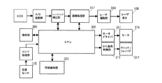
図1において400はドラム上のテスト濃度パターンのトナー画像濃度を測定する濃度測定手段である濃度センサ、401はその測定値を格納するメモリ、306は前記CPUであり、メモリ内の濃度に応じて高圧出力装置402及びレーザ406を調節する。407はドラムのホームポジションを示すホームポジションマーク、405は該ポジションを検出するホームポジションセンサ、404はドラムの回転量を検出するための回転軸上に備えられたエンコーダ、403はエンコーダ信号をカウントするカウンタである。
In FIG. 1, 400 is a density sensor which is a density measuring means for measuring the toner image density of a test density pattern on the drum, 401 is a memory for storing the measured value, and 306 is the CPU, which corresponds to the density in the memory. The high
図3で調整モードについて説明する。調整モードとはドラム上に濃度検出用のパターンを印字し、図示しない光学式の濃度センサによりドラムの副走査方向における各位置での濃度プロファイルデータを測定し、各回転位置でのレーザ光量(露光量)および現像高圧値を設定するものである。本実施例においてエンコーダのコードホイールには1周で800パルスを出力するものを使用している。ドラム上の副走査むら補正は、ドラム1周を80分割した領域ごとに補正するため、エンコーダパルス10発ごとにプロファイルを取得するものである。 The adjustment mode will be described with reference to FIG. In the adjustment mode, a pattern for density detection is printed on the drum, the density profile data at each position in the sub-scanning direction of the drum is measured by an optical density sensor (not shown), and the laser light quantity (exposure) at each rotational position is measured. Amount) and development high pressure value. In this embodiment, an encoder code wheel that outputs 800 pulses per round is used. In the sub-scanning unevenness correction on the drum, a profile is acquired for every 10 encoder pulses in order to correct for each area obtained by dividing the circumference of the drum into 80 parts.
F21で調整モードをスタートする。F22でドラムを回転駆動すると同時にドラムホームポジションの検出を開始する。F23でドラムのホームポジションを検出するとF24で濃度パターンの印字を開始する。同時にF25でエンコーダの出力値Ecをリセットし、F26でエンコーダのカウントを開始する。またF27で自然数mに0を入力する。F28でエンコーダカウント値Ecとm*10を比較し同値であればF29に進む。最初はm=0で一致するので領域0の設定値を導くためF29に進む。領域とはドラムの副走査方向に80分割した領域のことで0〜79領域まである。F29では領域0のパターンの濃度を測定する。F30で測定濃度の比較を行う。本複写機では最大ベタ濃度が1.6である。また印字パターン濃度は0.8としている。F30で濃度が1.2(第二の閾値)より高い、つまり濃度が非常に濃いと判断すると、F31で(1.2−0.8)*Aだけレーザ光量を下げるように領域0のレーザ光量値を設定する。このときのレーザ光量よりも下げていくと、レーザのリニアリティが失われる領域になる。ここでAは装置固有の定数である。次にレーザ光量だけでは補えない分をF32で補正する。すなわち、レーザ光量と現像高圧値の両方を変化させて補正を行う。F32では濃度1.2を超えた値に定数Bを乗じた量だけ現像高圧値を下げるように領域0の高圧値を設定する。F33で濃度が0.4(第一の閾値)より低いと判断した場合にはF34で(0.8−0.4)*Aだけレーザ光量を増やすように設定する。このときのレーザ光量よりも増やしていくとレーザの寿命が本体寿命より短くなってしまう。その後F35で(0.4−測定濃度)*Bだけ現像高圧値を増やすよう設定値を決める。測定濃度が0.4以上、1.2以下の場合にはF36でレーザの光量のみ設定値を変更する。次にF37でmが79になったかどうかを検出する。79未満の場合はF38でmにm+1を代入しF28からF37の制御を繰り返す。79になった場合にはF39で調整モードを終了する。上述した調整モードによりドラム上の0〜79までのレーザおよび高圧設定値が決定される。 The adjustment mode is started at F21. At F22, the drum home position is started at the same time as the drum is driven to rotate. When the drum home position is detected in F23, density pattern printing is started in F24. At the same time, the output value Ec of the encoder is reset at F25, and the count of the encoder is started at F26. In F27, 0 is input to the natural number m. In F28, the encoder count value Ec is compared with m * 10. Initially, since m = 0 and they match, the process proceeds to F29 in order to derive the set value of area 0. The area is an area divided into 80 in the sub-scanning direction of the drum, and is from 0 to 79 areas. In F29, the density of the pattern in region 0 is measured. The measured concentration is compared at F30. In this copying machine, the maximum solid density is 1.6. The print pattern density is 0.8. If it is determined that the density is higher than 1.2 (second threshold) at F30, that is, the density is very high, the laser in the region 0 is set so that the laser light amount is decreased by (1.2−0.8) * A at F31. Set the light intensity value. If the amount of laser light is lowered below that, the laser linearity is lost. Here, A is a constant unique to the apparatus. Next, the amount that cannot be compensated only by the amount of laser light is corrected by F32. That is, correction is performed by changing both the laser light quantity and the development high voltage value. In F32, the high pressure value in region 0 is set so as to lower the development high pressure value by an amount obtained by multiplying the value exceeding the density 1.2 by the constant B. If it is determined in F33 that the density is lower than 0.4 (first threshold value), the laser light amount is set to increase by (0.8−0.4) * A in F34. If the laser light quantity is increased at this time, the lifetime of the laser becomes shorter than the lifetime of the main body. Thereafter, the setting value is determined so as to increase the development high pressure value by (0.4−measured density) * B at F35. When the measured density is 0.4 or more and 1.2 or less, only the light amount of the laser is changed in F36. Next, it is detected at F37 whether m has reached 79. If it is less than 79, m + 1 is substituted for m in F38, and the control from F28 to F37 is repeated. If 79, the adjustment mode is terminated at F39. The adjustment mode described above determines the laser on the drum from 0 to 79 and the high pressure setpoint.
次にこの値を用いて通常プリントを行う際の制御について図4を用いて説明する。F1でプリント動作を開始する。F2でドラムを回転駆動しはじめると同時にドラムホームポジションの検出を行う。F3でドラムホームポジション検出をするとその検出信号によりF4でエンコーダカウント値Ecをリセットし、F5でエンコーダのカウントを開始する。F6で自然数nに0を代入する。nは前述したmと同じ領域を表す数字である。F7エンコーダカウント値Ecとn*10を比較し同値の場合には、F8で領域nに対するレーザ光量および現像高圧値により露光および高圧出力を行う。F9でn=79でない場合はF10でnにn+1を代入しF7からF9の制御を繰り返す。F9でn=79となった場合にはF11で印字終了かどうか判断し印字が終了していない場合はF3からF11の制御を繰り返す。印字終了の場合にはF12で印字を終了する。 Next, control when performing normal printing using this value will be described with reference to FIG. Printing operation is started at F1. At F2, the drum home position is detected at the same time as the drum starts to rotate. When the drum home position is detected in F3, the encoder count value Ec is reset in F4 by the detection signal, and the encoder count is started in F5. In F6, 0 is substituted for the natural number n. n is a number representing the same region as m described above. If the F7 encoder count value Ec and n * 10 are the same, exposure and high pressure output are performed with the laser light quantity and the development high pressure value for the region n in F8. If n is not 79 in F9, n + 1 is substituted for n in F10 and the control from F7 to F9 is repeated. When n = 79 in F9, it is determined whether or not printing is finished in F11. If printing is not finished, the control from F3 to F11 is repeated. When printing is completed, printing is terminated at F12.
上記制御を行うことで、副走査方向の濃度むら補正を広範囲にわたり行うことが可能な画像形成装置を提供することが可能となる。 By performing the above control, it is possible to provide an image forming apparatus capable of correcting density unevenness in the sub-scanning direction over a wide range.
1 リーダ部
2 プリンタ部
3 複写機
4 装置本体
6 画像形成部
103 光源
106 光電変換/画像処理部
107 画像処理部
108 レーザ素子(露光手段に対応)
110 現像器
112 感光体ドラム
113 一次帯電器
116 クリーナ
120 定着器
304 レーザ駆動部
305 操作部
306 CPU
307 モータドライバ
311 DC負荷制御部
315 各種センサ
316 モータ(駆動手段に対応)
317 クラッチ/ソレノイド
320 厚紙検知部
400 濃度センサ
401 メモリ
402 高圧出力装置(高圧出力手段に対応)
403 カウンタ
404 エンコーダ
405 HPセンサ
406 レーザ
407 ホームポジション
DESCRIPTION OF
110
307
317 Clutch /
403
Claims (3)
前記感光体ドラムを回転駆動する駆動手段と、
前記感光体ドラムに潜像を形成するための露光手段と、
前記感光体ドラムを帯電させるための高圧出力を出力するための高圧出力手段を有する画像形成装置において、
前記感光体ドラムの回転位置に応じて、前記露光手段の露光量と前記高圧出力手段の高圧出力を変化させることにより、
前記感光体ドラムの感度むらおよび帯電むらを低減させることを特徴とする画像形成装置。 A photosensitive drum, and driving means for rotationally driving the photosensitive drum;
Exposure means for forming a latent image on the photosensitive drum;
In an image forming apparatus having a high voltage output means for outputting a high voltage output for charging the photosensitive drum,
By changing the exposure amount of the exposure unit and the high voltage output of the high voltage output unit according to the rotational position of the photosensitive drum,
An image forming apparatus characterized by reducing unevenness in sensitivity and unevenness in charging of the photosensitive drum.
前記濃度測定手段の測定値が第一のしきい値より小さい場合、もしくは第二のしきい値より大きい場合には前記露光手段の露光量および前記高圧出力手段の高圧出力の両方を変化させ、
前記測定値が前記第一のしきい値より大きく、前記第二のしきい値より小さい場合には前記露光手段の露光量を変化させることによって、
前記感光体ドラムの感度むらおよび帯電むらを低減させることを特徴とする請求項1に記載の画像形成装置。 Density measuring means for measuring the density of a toner image formed from a latent image on the photosensitive drum;
When the measured value of the density measuring means is smaller than the first threshold value or larger than the second threshold value, both the exposure amount of the exposing means and the high voltage output of the high voltage output means are changed,
By changing the exposure amount of the exposure means when the measured value is larger than the first threshold value and smaller than the second threshold value,
The image forming apparatus according to claim 1, wherein unevenness in sensitivity and unevenness in charging of the photosensitive drum is reduced.
前記感光体ドラム上のホームポジションマークと、
前記ホームポジションマークを検出するセンサと、
前記感光体ドラムの回転軸上に備えられたエンコーダと、
前記エンコーダの信号をカウントするカウンタと、
前記カウンタを前記センサの検出信号によりリセットするリセット手段を備え、
前記カウンタの出力値に応じて、前記メモリから前記プロファイルデータを呼び出し、該データに応じた高圧出力を前記高圧出力手段が出力することを特徴とする請求項2に記載の画像形成装置。 A memory for storing profile data in the sub-scanning direction of the photosensitive drum constituted by the measured value of the toner image density obtained by the density measuring means;
A home position mark on the photosensitive drum;
A sensor for detecting the home position mark;
An encoder provided on a rotating shaft of the photosensitive drum;
A counter that counts the encoder signal;
Resetting means for resetting the counter by a detection signal of the sensor;
The image forming apparatus according to claim 2, wherein the profile data is called from the memory in accordance with an output value of the counter, and the high voltage output unit outputs a high voltage output corresponding to the data.
Priority Applications (1)
| Application Number | Priority Date | Filing Date | Title |
|---|---|---|---|
| JP2008051925A JP2009210697A (en) | 2008-03-03 | 2008-03-03 | Image forming apparatus |
Applications Claiming Priority (1)
| Application Number | Priority Date | Filing Date | Title |
|---|---|---|---|
| JP2008051925A JP2009210697A (en) | 2008-03-03 | 2008-03-03 | Image forming apparatus |
Publications (2)
| Publication Number | Publication Date |
|---|---|
| JP2009210697A true JP2009210697A (en) | 2009-09-17 |
| JP2009210697A5 JP2009210697A5 (en) | 2011-04-14 |
Family
ID=41183940
Family Applications (1)
| Application Number | Title | Priority Date | Filing Date |
|---|---|---|---|
| JP2008051925A Withdrawn JP2009210697A (en) | 2008-03-03 | 2008-03-03 | Image forming apparatus |
Country Status (1)
| Country | Link |
|---|---|
| JP (1) | JP2009210697A (en) |
Cited By (2)
| Publication number | Priority date | Publication date | Assignee | Title |
|---|---|---|---|---|
| JP2011170156A (en) * | 2010-02-19 | 2011-09-01 | Ricoh Co Ltd | Image forming apparatus |
| JP2012237875A (en) * | 2011-05-12 | 2012-12-06 | Ricoh Co Ltd | Image forming apparatus |
-
2008
- 2008-03-03 JP JP2008051925A patent/JP2009210697A/en not_active Withdrawn
Cited By (2)
| Publication number | Priority date | Publication date | Assignee | Title |
|---|---|---|---|---|
| JP2011170156A (en) * | 2010-02-19 | 2011-09-01 | Ricoh Co Ltd | Image forming apparatus |
| JP2012237875A (en) * | 2011-05-12 | 2012-12-06 | Ricoh Co Ltd | Image forming apparatus |
Similar Documents
| Publication | Publication Date | Title |
|---|---|---|
| JP2014119713A (en) | Image forming apparatus | |
| JP4890810B2 (en) | Image forming apparatus | |
| JP4989163B2 (en) | Image forming apparatus and control method thereof | |
| US7865095B2 (en) | Image forming apparatus including distance detection unit | |
| JP5272105B2 (en) | Image forming apparatus | |
| JP5975975B2 (en) | Image reading apparatus, image forming apparatus, and document width detection method | |
| JP2012133052A (en) | Image forming apparatus | |
| JP2009210697A (en) | Image forming apparatus | |
| JP2010107856A (en) | Image forming apparatus | |
| JP5624968B2 (en) | Image forming apparatus | |
| JP5826352B2 (en) | Image forming apparatus | |
| JP7096974B2 (en) | Image forming device | |
| JP2009300491A (en) | Image forming apparatus | |
| JP5222623B2 (en) | Image forming apparatus | |
| JP2011027916A (en) | Image forming apparatus | |
| JP2010224497A (en) | Image forming device | |
| JP2005309050A (en) | Image forming apparatus | |
| US20120183316A1 (en) | Interdocument photoreceptor signal sensing and feedback control of paper edge ghosting | |
| JP2006267597A (en) | Image forming apparatus | |
| JP2005266690A (en) | Image forming apparatus | |
| JP6197566B2 (en) | Image forming apparatus | |
| JP2009300834A (en) | Image forming apparatus | |
| US20230066316A1 (en) | Image forming apparatus | |
| JP2008276134A (en) | Image forming apparatus | |
| JP6748922B2 (en) | Image forming device |
Legal Events
| Date | Code | Title | Description |
|---|---|---|---|
| A521 | Written amendment |
Free format text: JAPANESE INTERMEDIATE CODE: A523 Effective date: 20110302 |
|
| A621 | Written request for application examination |
Free format text: JAPANESE INTERMEDIATE CODE: A621 Effective date: 20110302 |
|
| RD05 | Notification of revocation of power of attorney |
Free format text: JAPANESE INTERMEDIATE CODE: A7425 Effective date: 20120125 |
|
| A761 | Written withdrawal of application |
Free format text: JAPANESE INTERMEDIATE CODE: A761 Effective date: 20120201 |
|
| RD03 | Notification of appointment of power of attorney |
Free format text: JAPANESE INTERMEDIATE CODE: A7423 Effective date: 20120208 |