JP2009208894A - Printing device - Google Patents
Printing device Download PDFInfo
- Publication number
- JP2009208894A JP2009208894A JP2008053439A JP2008053439A JP2009208894A JP 2009208894 A JP2009208894 A JP 2009208894A JP 2008053439 A JP2008053439 A JP 2008053439A JP 2008053439 A JP2008053439 A JP 2008053439A JP 2009208894 A JP2009208894 A JP 2009208894A
- Authority
- JP
- Japan
- Prior art keywords
- paper
- printing
- printing paper
- tray
- feeding
- Prior art date
- Legal status (The legal status is an assumption and is not a legal conclusion. Google has not performed a legal analysis and makes no representation as to the accuracy of the status listed.)
- Withdrawn
Links
Images


Abstract
Description
この発明は、印刷位置において印刷用紙に印刷を行う印刷装置に関するものである。 The present invention relates to a printing apparatus that performs printing on printing paper at a printing position.
従来、特許文献1に記載の印刷装置のように、印刷装置が印刷用紙の残数に関する情報を保持したものが知られている。このように構成すると、印刷用紙の残り枚数でホストコンピュータから印刷要求があれば、印刷装置が保持する印刷用紙の残数に関する情報に基づいて、ホストコンピュータから入力された印刷データの全てを印字することができるか否かを判断することができる。そして、印刷用紙の残り枚数では印刷データの全てを印刷できないと判断したときには、印刷用紙が不足する旨と、不足する印刷用紙の枚数をホストコンピュータに通知するように構成されているので、印刷を開始する際に、ホストコンピュータにおいて印刷用紙の補給の必要性の有無を判断できる。
2. Description of the Related Art Conventionally, like a printing apparatus described in
ところで、上記した印刷装置では、ホストコンピュータから当該印刷装置が貯蔵可能な印刷用紙の枚数の上限を超える量の印刷を要求され、印刷の途中で用紙の補給を行う必要がある場合については一切考慮されておらず、技術の改善が求められていた。 By the way, in the above-described printing apparatus, there is no consideration when the host computer requires printing exceeding the upper limit of the number of printing sheets that can be stored by the printing apparatus, and it is necessary to replenish the sheets in the middle of printing. It wasn't done, and there was a need for technical improvements.
この発明は、上記課題に鑑みなされたものであり、印刷用紙の補給を効率よく行うことのできる印刷装置を提供することを目的とする。 The present invention has been made in view of the above problems, and an object thereof is to provide a printing apparatus that can efficiently replenish printing paper.
この発明にかかる印刷装置は、上記目的を達成するため、印刷位置において印刷用紙に印刷を行う印刷装置において、複数の印刷用紙を貯蔵する用紙トレイと、前記用紙トレイから前記印刷用紙を前記印刷位置に送り込む用紙送り手段と、前記用紙トレイに設けられ、該用紙トレイに貯蔵された前記印刷用紙の有無を検出する印刷用紙検出手段と、前記用紙送り手段による前記印刷用紙の前記印刷位置への送り込み時に、前記印刷用紙検出手段が前記用紙トレイに後続する前記印刷用紙が無い状態であることを検出すれば、当該用紙無し状態を報知する報知手段とを備えていることを特徴としている。 In order to achieve the above object, a printing apparatus according to the present invention is a printing apparatus that performs printing on printing paper at a printing position, a paper tray that stores a plurality of printing paper, and the printing paper from the paper tray at the printing position. A paper feeding means for feeding the paper, a printing paper detection means for detecting the presence or absence of the printing paper stored in the paper tray, and at the time of feeding the printing paper to the printing position by the paper feeding means, If the printing paper detection means detects that there is no printing paper following the paper tray, the printing paper detection means comprises notification means for notifying the absence of paper.
このように構成された発明では、用紙送り手段による印刷用紙の印刷位置への送り込み時に、印刷用紙検出手段が用紙トレイに後続する印刷用紙が無い状態であることを検出すれば、当該用紙無し状態が報知手段により報知されるので、ユーザはこの報知に応じて印刷用紙の補給準備をすることで、印刷位置への送り込みが行われている印刷用紙への印刷が終了した直後に印刷用紙の補給を行うことができる。また、報知手段による報知の後は、ユーザは複数の印刷用紙への印刷が終了するのを待機せずとも、印刷位置への送り込み中の印刷用紙への印刷が終了するのを待機するのみで、効率よく印刷用紙の補給を行うことができる。 In the invention configured as described above, when the printing paper detection unit detects that there is no printing paper following the paper tray when the printing paper is fed to the printing position by the paper feeding unit, the no-paper state is determined. Since the notification means notifies the user, the user prepares for the supply of the printing paper in response to the notification, so that the printing paper is supplied immediately after the printing on the printing paper that has been sent to the printing position is completed. It can be carried out. Further, after the notification by the notification means, the user does not wait for the printing on the plurality of printing papers to end, but only waits for the printing on the printing paper being sent to the printing position to end. The printing paper can be replenished efficiently.
また、前記用紙トレイは複数サイズの前記印刷用紙を貯蔵可能に構成されており、前記印刷用紙検出手段は、前記複数サイズのうち、最小サイズの前記印刷用紙が前記用紙トレイに貯蔵された状態における当該印刷用紙の前記用紙送り手段による送り方向と反対側の端部に配設されている構成としてもよい。このような構成とすれば、最小サイズの印刷用紙の検出が可能な位置に印刷用紙検出手段が配設されているため、用紙トレイに貯蔵される全てのサイズの印刷用紙の有無を検出できる。また、印刷を行う印刷用紙がどのようなサイズであっても、印刷用紙の用紙送り手段による送り方向と反対側の端部が、当該印刷用紙が印刷位置へ送り込まれることにより印刷用紙検出手段が配設された位置を越えた時から、当該印刷用紙への印刷が終了するまでの時間をほぼ同じ時間とすることができる。したがって、どのサイズの印刷用紙に印刷を行っても、印刷用紙検出手段による印刷用紙の有無の検出結果に基づく報知手段による報知の後、印刷が終了して印刷用紙の補給が可能となるまでの時間がほぼ同じとなるため、ユーザの利便性を高めることができる。 Further, the paper tray is configured to be capable of storing a plurality of sizes of the printing paper, and the printing paper detection means is in a state in which the printing paper having the smallest size among the plurality of sizes is stored in the paper tray. It is good also as a structure arrange | positioned at the edge part on the opposite side to the feed direction by the said paper feed means of the said printing paper. With such a configuration, since the printing paper detection unit is disposed at a position where the printing paper of the minimum size can be detected, it is possible to detect the presence or absence of printing paper of all sizes stored in the paper tray. In addition, regardless of the size of printing paper to be printed, the end of the printing paper opposite to the feeding direction by the paper feeding means is sent to the printing position by the printing paper detection means. The time from when the set position is exceeded to when the printing on the printing paper is completed can be set to substantially the same time. Therefore, no matter what size printing paper is printed, after the notification by the notification means based on the detection result of the presence or absence of the printing paper by the printing paper detection means, the printing is completed and the printing paper can be replenished Since the time is substantially the same, the convenience for the user can be improved.
また、前記印刷用紙検出手段は、発光手段と、前記発光手段からの光を直接受光、または、前記発光手段からの光の前記印刷用紙による反射光を受光する受光手段とを備える構成でもよい。このような構成とすれば、発光手段と受光手段により印刷用検出手段を容易に実現できる。 The printing paper detecting unit may include a light emitting unit and a light receiving unit that directly receives light from the light emitting unit or receives light reflected by the printing paper from the light emitting unit. With such a configuration, the print detecting means can be easily realized by the light emitting means and the light receiving means.
また、前記印刷位置において、前記用紙送り手段による前記印刷用紙の送り方向とほぼ直交する主走査方向に往復移動することにより前記印刷用紙に印刷を行うプリントヘッドを備える構成でもよい。プリントヘッドが主走査方向に往復移動して印刷用紙に印刷を行う、いわゆる、シリアルプリンタはレーザープリンタなどのページプリンタに比べると、印刷用紙1枚を印刷するのにより多くの時間を必要とする。しかしながら、用紙無し状態が報知手段により報知された後に印刷用紙の補給準備をすることで、ユーザは印刷位置へ送り込み中の印刷用紙に対する印刷が終了するのを待機するのみで印刷用紙の補給を行うことができ、非常に効率よく印刷用紙の補給を行うことができる。 The printing position may include a print head that performs printing on the printing paper by reciprocating in a main scanning direction substantially orthogonal to the feeding direction of the printing paper by the paper feeding means. A so-called serial printer, in which a print head moves back and forth in the main scanning direction and prints on printing paper, requires more time to print one printing paper than a page printer such as a laser printer. However, by preparing for replenishment of the printing paper after the notification of the paper out condition, the user replenishes the printing paper only by waiting for the printing on the printing paper being sent to the printing position to end. And printing paper can be replenished very efficiently.
図1は本発明の印刷装置の一実施形態であるカラー印刷を行うインクジェットプリンタ1を示す斜視図である。また、図2はインクジェットプリンタ1の要部拡大図であり、(a)は自動給紙装置3および用紙トレイ4を示す図、(b)は用紙センサ16の構成を示す図である。また、図3はインクジェットプリンタ1の内部構成の概略を示す図である。また、図4は印刷用紙送り込み動作を示す図であり、(a)は用紙トレイ4から印刷位置PPへの印刷用紙Pの自動給紙装置3による送り込みが開始された状態を示す図であり、(b)の印刷用紙Pの先端が印刷位置PPまで送り込まれた状態を示す図であり、(c)は印刷用紙Pの後端が用紙センサ16の位置を越えた状態を示す図である。このインクジェットプリンタ1では、プリンタ本体2の内部にはプリント機構50(図3参照)が内蔵されており、インクジェットプリンタ1の全体の制御を司るコントローラ20(図3参照)からの動作指令に応じて印刷用紙Pへの印刷を実行する。そして、こうして印刷された印刷用紙がプリンタ本体2の前面に排紙される。
FIG. 1 is a perspective view showing an
また、プリンタ本体2の背面側に自動給紙手段としての自動給紙装置(本発明の「用紙送り手段」に相当)3が配設されている。自動給紙装置(Auto Sheet Feeder)3には、複数の印刷用紙Pを貯蔵する用紙トレイ4と、載置板5およびエッジガイド6を有する用紙ガイド7が取付けられている。また、自動給紙装置3は用紙トレイ4に貯蔵された印刷用紙Pを用紙ガイド7に沿って1枚ずつプリンタ本体2内の印刷位置PPに送り込む用紙送り機構を備えている(図4参照)。また、後で図3を参照して詳述するように、プリンタ本体2内には、用紙送り機構による印刷用紙Pの送り方向(副走査方向)とほぼ直交する幅方向(主走査方向)に往復移動するキャリッジ53が設けられ、キャリッジ53の下部に設けられ、キャリッジ53と一体的に往復移動する印刷ヘッド(本発明の「プリントヘッド」に相当)55から所定のタイミングでインクが吐出されることにより印刷位置PPにおいて印刷用紙Pに印刷が行われる。そして、プリンタ本体2の前側下部に開口する排出口2aから印刷された印刷用紙が排出される。
Further, an automatic paper feeding device (corresponding to “paper feeding means” of the present invention) 3 as an automatic paper feeding means is disposed on the back side of the printer
また、図2(a)に示すように、用紙ガイド7が有するエッジガイド6の位置調整を行って幅を調整することで、用紙トレイ4はL判サイズ〜A4サイズまでの複数サイズの印刷用紙Pを貯蔵可能に構成されている。また、用紙トレイ4が貯蔵可能な複数の印刷用紙のサイズのうち、最小サイズであるL判サイズの印刷用紙Pが用紙トレイ4に貯蔵された状態における当該印刷用紙Pの用紙送り方向とは反対側の後端側に、用紙トレイ4に貯蔵された印刷用紙Pの有無を検出する印刷用紙検出センサ(本発明の「印刷用紙検出手段」に相当)16が配設されている。図2(b)に示すように、この印刷用紙検出センサ16は、発光ダイオードなどにより構成される発光手段16aと、フォトトランジスタなどの受光センサにより構成され発光手段16aからの光L1の印刷用紙Pによる反射光L2を受光する受光手段16bとを備えている。すなわち、発光手段16aから発した光L1は印刷用紙Pにより反射され、その反射光L2は受光手段16bで受光されて電気信号に変換される。そして、受光した反射光L2の強さに応じた受光センサの出力値として、電気信号の大きさが測定される。
Further, as shown in FIG. 2A, by adjusting the position of the
なお、本実施形態では、図2(b)に示すように、発光手段16aと受光手段16bとが一体的に反射型の印刷用紙検出センサ16を構成するようにしたが、発光手段と受光手段とをそれぞれ個別の機器で構成してもよい。また、発光手段と受光手段とを対向配置し、受光手段が発光手段からの光を直接受光するようにして、いわゆる、フォトインタラプタとして印刷用紙検出センサを構成してもよい。このような構成とすれば、印刷用紙Pが発光手段と受光手段との間に位置し、発光手段から受光手段への光が遮断されることにより、用紙トレイ4上の印刷用紙Pの有無を検出できる。
In the present embodiment, as shown in FIG. 2B, the light emitting means 16a and the light receiving means 16b integrally constitute the reflective printing
また、印刷用紙Pが無くなったり、紙詰まりなどのエラーが生じた場合に、任意のタイミングでユーザに対してビープ音により情報を報知することができるようにブザー34を備えている(本発明の「報知手段」に相当、図3参照)。このような構成とすれば、インクジェットプリンタ1に何らかのエラーが生じて印刷が中断したことを、確実にユーザに報知することができる。
Further, a
次に、図3を参照して、用紙トレイ4から送り込まれた印刷用紙Pに対して印刷を実行するプリント機構50について説明する。このプリント機構50には、図3に示すように、キャリッジ53が左右方向にループ状に架け渡されたタイミングベルト51により駆動されガイド52に沿って左右(主走査方向)に往復動する。このキャリッジ53には、紙端検出センサ57が設けられ、用紙Pの左右端や上下端を検出する。つまり、紙端検出センサ57は、用紙トレイ4から送り込まれた印刷用紙Pに対して印刷前にキャリッジ53が左右方向に走査したときにその印刷用紙Pの左右端を検出して用紙幅の認識を可能にしたり、印刷途中で印刷用紙Pの後端を検出して用紙長さの認識を可能にしたりする。
Next, with reference to FIG. 3, the
また、このキャリッジ53には、シアン・マゼンタ・イエロー・ブラック等の各色のインクを個別に収容したインクカートリッジ54が搭載されている。これらのインクカートリッジ54はそれぞれ印刷ヘッド55に接続されている。そして、印刷ヘッド55はインクカートリッジ54からのインクに圧力をかけてノズル(図示省略)から印刷用紙Pに向かってインクを吐出する。この実施形態では、印刷ヘッド55は圧電素子に電圧をかけることにより該圧電素子を変形させてインクを加圧する方式を採用しているが、発熱抵抗体(例えばヒータなど)に電圧をかけインクを加熱して発生した気泡によりインクを加圧する方式を採用してもよい。こうして印刷された印刷用紙Pは搬送ローラ56によって排出口2aへ送り出される。
The
次に、図3を参照して、インクジェットプリンタ1のコントローラ20の構成について説明する。図3に示すように、本実施形態のインクジェットプリンタ1は、USBインターフェースやパラレルインターフェースなどにより構成されたインターフェース24を介してホストコンピュータPCと通信可能に接続されるように構成されている。そして、ホストコンピュータPCでは、プログラムおよびCPUにより構成されたプリンタドライバにより、画像データや文書データを印刷データに変換する処理が実行され、これらの印刷データおよび印刷指令がホストコンピュータPCからインクジェットプリンタ1に送信される。
Next, the configuration of the
また、インターフェース24に接続されたコントローラ20のシステムバス21には、CPU25、ROM26、RAM27、ASIC28、不揮発性メモリ(図示省略)などが接続されている。CPU25は、プリント機構50の動作制御を実行するための演算処理などを行う。また、CPU25は、ROM26に記憶されたプログラムを実行することでASIC28に対し印刷制御において必要な指令や、印刷用紙Pの送り込み処理および排出処理の指令を出力するように構成されている。ROM26は、CPU25の制御に必要なプログラム(ファームウェア)などを記憶する。RAM27には一時的に外部から入力された印刷データなどのデータが記憶され、不揮発性メモリにはCPU25の制御に必要な各種データやテーブルなどが格納される。
Further, a
また、ASIC28には、ヘッド駆動回路31、ベルト駆動回路32、ローラ駆動回路33が接続されている。そして、ASIC28はヘッド駆動回路31を介して印刷ヘッド55を制御することにより印刷用紙Pに対してインクを吐出し、ベルト駆動回路32を介してキャリッジモータ(図示省略)を制御することによりキャリッジ53の往復移動を実行し、ローラ駆動回路33を介して紙送りモータ(図示省略)を制御することにより搬送ローラ56、紙送りローラ13およびローディングローラ10(図4参照)をそれぞれ任意のタイミングで回転させる。
In addition, a
また、ASIC28はホストコンピュータPCから入力された印刷データのコマンドを解釈するとともにデータ展開を行い、このデータなどに基づいてヘッド駆動回路31を介して印刷ヘッド55を制御するように構成されている。このように、ASIC28は、プリント機構50を駆動して印刷制御を行うとともに、CPU25の指令に基づいて印刷用紙Pの送り込み処理および排出処理を行う。
The
次に、図4を参照して、自動給紙装置3の構成および動作について説明する。図4に示すように、プリンタ本体2の背面部にある載置板5の下端付近に、ローディングローラ10が載置板5に対向して配置されている。また、ローディングローラ10の用紙送り方向の下流側には、ガイド12が配置されている。そして、図4(a)に示すように、用紙トレイ4および載置板5上の印刷用紙Pのうち一番上の1枚にローディングローラ10がその円弧面で当接しながら同図(a)中の矢印の方向に1回転することで、その印刷用紙Pが紙送りローラ13まで送り込まれる。なお、図4に示す例では、印刷用紙送り込み動作の説明を簡単に行うために、用紙トレイ4に印刷用紙Pが1枚のみ貯蔵されている場合について説明するが、用紙トレイ4には複数の印刷用紙Pを貯蔵してもよいことは言うまでもない。
Next, the configuration and operation of the automatic paper feeder 3 will be described with reference to FIG. As shown in FIG. 4, a
また、上記したように、ローディングローラ10、紙送りローラ13および搬送ローラ56はローラ駆動手段33により駆動される紙送りモータにより回転されるように構成されている。また、ローディングローラ10と紙送りモータとは、動力伝達の切断・接続の切換えをするクラッチを介して連結されている。したがって、用紙トレイ4から印刷用紙Pを紙送りローラ13まで送り込むときはクラッチが接続状態に切換えられ、これによりローディングローラ10が駆動される。
Further, as described above, the
また、本実施形態では、紙送りモータはステッピングモータにより構成されており、ASIC28は、紙送りモータのステップ数を計数する計測手段としてのカウンタ(図示省略)を備えている。したがって、ASIC28はカウンタの計数値から印刷用紙Pの位置を検出することができる。なお、紙送りモータの回転をエンコーダで検出し、エンコーダからのパルスエッジをカウンタにより計数して印刷用紙Pの位置を検出する構成でもよい。
In the present embodiment, the paper feed motor is a stepping motor, and the
そして、図4(b)に示すように、印刷用紙Pが紙送りローラ13の回転により所定量送り込まれることで、印刷用紙Pの先端が印刷ヘッド55の基準位置(同図(b)中の矢印の位置)に一致する位置に位置決めされる。すなわち、用紙トレイ4から送り込まれた印刷用紙Pは、紙送りローラ13間を通ってキャリッジ53とプラテン14との間の印刷位置PPに送り込まれて頭出しされる。
Then, as shown in FIG. 4B, when the printing paper P is fed by a predetermined amount by the rotation of the
なお、プリント機構50に送り込まれた印刷用紙Pへの印刷が終了し、搬送ローラ56により印刷用紙Pが排出口2aから排出されることにより、印刷用紙Pの後端が印刷位置PPに至ったのを紙端検出センサ57が検出してから、さらに所定量だけ印刷用紙Pが排出口2aから排出されたタイミングで、用紙トレイ4から次の印刷用紙Pの印刷位置PPへの送り込みが開始される。本実施形態では、前の印刷用紙Pが排出口2aから排出されている途中であって、後続する印刷用紙Pの先端が頭出しの基準位置送り込まれた時に、前の印刷用紙Pが搬送ローラ56から落ちるタイミングで、後続する印刷用紙Pの印刷位置PPへの送り込み開始されるように構成されている。
Note that printing on the printing paper P sent to the
一方、図4(c)に示すように、印刷用紙Pに対する印刷処理に伴って当該印刷用紙Pが印刷位置PPに向けて送り込まれている時に、用紙トレイ4に後続する印刷用紙Pが無い状態であれば、印刷中の印刷用紙Pの後端が印刷用紙検出センサ16の位置を越えれば、この印刷用紙検出センサ16が用紙トレイ4に後続する印刷用紙Pが無い状態であることを検出するように構成されている。
On the other hand, as shown in FIG. 4C, when the printing paper P is sent toward the printing position PP in accordance with the printing process on the printing paper P, there is no printing paper P following the paper tray 4. If the trailing edge of the printing paper P being printed exceeds the position of the printing
ところで、複数の印刷用紙Pに対して連続して印刷が実行され、用紙トレイ4からの印刷用紙Pの印刷位置PPへの送り込みが連続して行われているときに、用紙トレイ4に印刷用紙Pを補給すれば、紙詰まりなどを発生させるおそれがあった。したがって、用紙トレイ4に印刷用紙Pを補給するときは、ホストコンピュータPCから受信した全印刷データについての印刷が終了した状態のときか、用紙トレイ4に貯蔵された全ての印刷用紙Pに対して印刷が行われたことにより、用紙切れとして印刷が一時停止された状態のときに、用紙トレイ4に印刷用紙Pを補給する必要があった。そのため、印刷の途中で、ユーザは用紙トレイ4に貯蔵された印刷用紙Pが無くなったかどうかを度々確認する必要があり、非常に煩わしかった。また、用紙トレイ4に数枚の印刷用紙Pが残っている状態で、用紙トレイ4から印刷用紙Pが無くなるのを待機する場合には、数枚の印刷用紙Pが無くなるまでユーザが待機する時間が無駄であった。特に、インクジェットプリンタなどのシリアルプリンタでは、印刷速度が遅いため、数枚の印刷用紙Pへの印刷であっても、印刷が終了するまでユーザは長時間待機することを要求され、時間の無駄が多いという不都合があった。 By the way, when printing is continuously performed on a plurality of printing papers P and the printing paper P is continuously fed from the paper tray 4 to the printing position PP, the printing paper is placed on the paper tray 4. If P is replenished, there is a risk of causing a paper jam or the like. Therefore, when the printing paper P is replenished to the paper tray 4, when all the printing data received from the host computer PC has been printed, or for all the printing paper P stored in the paper tray 4. When printing is performed, it is necessary to replenish printing paper P to the paper tray 4 when printing is temporarily stopped due to running out of paper. Therefore, during printing, the user has to check frequently whether or not the printing paper P stored in the paper tray 4 is exhausted, which is very troublesome. In addition, when waiting for the printing paper P to run out of the paper tray 4 in a state where several printing papers P remain in the paper tray 4, the user waits until several printing papers P run out. Was useless. In particular, serial printers such as inkjet printers are slow in printing speed, so even when printing on several printing papers P, the user is required to wait for a long time until printing is completed, and time is wasted. There was inconvenience that there were many.
また、従来のインクジェットプリンタでは、最後の印刷用紙Pに対する印刷が終了した後、上記したタイミングで、次の印刷用紙Pの印刷位置PPへの送り込み動作を開始し、所定時間、ローディングローラ10および紙送りローラ13を駆動させたにもかかわらず、次の印刷用紙Pの先端が紙端検出センサ57により検出されなかった場合に、用紙トレイ4に後続する印刷用紙Pが無い状態であることを検出するように構成されていた。したがって、用紙トレイ4に印刷用紙Pが無い状態であることをユーザに報知する構成とした場合には、最後の印刷用紙Pへの印刷が終了した後、次の印刷用紙Pが用紙トレイ4に無い状態であることが検出されるまでに所定時間を要したので、次のような点について技術の改善が求められていた。すなわち、最後の印刷用紙Pに対する印刷が終了した後、相当の時間が経過した後に用紙トレイ4に印刷用紙Pが無い状態であることが検出されて、用紙無し状態であることがユーザに報知される。ユーザは、この報知に応じて印刷用紙Pの補給準備を開始することとなるため、効率が悪かった。特に家庭用のプリンタのように、用紙トレイ4に大量の印刷用紙Pを貯蔵することができないタイプのプリンタでは、用紙トレイ4への印刷用紙Pの補給作業の頻度が高まることとなるため、これにより上記した問題が顕著となる。
Further, in the conventional ink jet printer, after the printing on the last printing paper P is completed, the feeding operation of the next printing paper P to the printing position PP is started at the above-described timing, and the
ところが、本実施形態のインクジェットプリンタ1では、印刷用紙検出センサ16を備えることにより、印刷用紙Pに対する印刷が終了する前に、用紙トレイ4に後続する印刷用紙Pが無い状態であることを検出することができる。そして、本実施形態では、図4(c)に示すように、自動給紙装置3による印刷用紙Pの印刷位置PPへの送り込み時に、用紙トレイ4に後続する印刷用紙Pが無い状態であることを印刷用紙検出センサ16が検出すれば、当該用紙無し状態をブザー34を鳴らすことによりユーザに報知するように構成されている。この用紙無し状態検出時処理について、図4および図5を参照して説明する。
However, in the
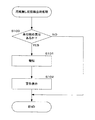
図5は用紙無し状態検出時処理を示す図である。図4(c)に示すように、印刷用紙検出センサ16が用紙トレイ4に後続する印刷用紙Pが無い状態であることを検出すれば図5に示す用紙無し状態検出時処理がコントローラ20により実行される。印刷用紙検出センサ16により用紙無し状態が検出されれば、まず、ステップS100において、ホストコンピュータPCから入力された印刷データのうち未印刷の頁が無いかどうかが判定される。ステップS100においてNOと判定されればそのまま処理を終了する。一方、ステップS100においてYESと判定されれば、ブザー34を鳴らすことにより、ユーザに対して用紙トレイ4に印刷用紙Pが無い状態であることが報知される(ステップS101)。そして、ブザー34よる用紙無し状態のユーザへの報知後、図示省略したインクジェットプリンタ1が備える液晶モニタに、用紙トレイ4が用紙無し状態であることの警告を表示して処理を終了する(ステップS102)。
FIG. 5 is a diagram showing processing at the time of detecting a paper out state. As shown in FIG. 4C, if the printing
なお、本実施形態では、ブザー34および液晶モニタによりユーザに対する報知を行ったが、これらに代えてLEDなどの発光素子によりユーザに対する報知を行ってもよい。また、上記したブザー34、液晶モニタおよび発光素子を、それぞれ単独で、または組合わせて本発明の「報知手段」を構成できる。また、本実施形態では、ステップS100において、印刷データのうち、未印刷の頁があるかどうかの判定結果に応じて、ユーザに用紙無し状態を報知するように構成したが、印刷用紙検出センサ16が用紙トレイ4の用紙無し状態を検出すれば、常にユーザに用紙無し状態を報知するように構成してもよい。
In the present embodiment, the user is notified by the
以上のように、この実施形態では、自動給紙装置3による印刷用紙Pの印刷位置PPへの送り込み時に、印刷用紙検出センサ16が用紙トレイ4に後続する印刷用紙Pが無い状態であることを検出すれば、当該用紙無し状態がブザー34により報知されるので、ユーザはこの報知に応じて印刷用紙Pの補給準備をすることで、印刷位置PPへの送り込みが行われている印刷用紙Pへの印刷が終了した直後に印刷用紙Pの補給を行うことができる。また、ブザー34による報知の後は、ユーザは複数の印刷用紙Pへの印刷が終了するのを待機せずとも、印刷位置PPへの送り込み中の印刷用紙Pへの印刷が終了するのを待機するのみで、効率よく印刷用紙Pの補給を行うことができる。
As described above, in this embodiment, when the automatic paper feeder 3 feeds the printing paper P to the printing position PP, the printing
また、上記した従来の印刷装置のように、印刷装置が用紙トレイ4に貯蔵された印刷用紙Pの残数に関する情報を保持した構成では、印刷用紙Pが複数枚重なってプリント機構50に送り込まれた(重送された)場合、印刷装置が保持した印刷用紙Pの残数に関する情報と、実際にトレイ4に残っている印刷用紙Pの枚数との間に誤差が生じるため、誤動作の原因となっていた。しかしながら、この実施形態では、用紙トレイ4から印刷用紙Pがプリント機構50に送り込まれる時に重送が生じても、用紙トレイ4に後続する印刷用紙Pがあるか無いかについての印刷用紙検出センサ16による検出結果のみを用いて、用紙トレイ4の用紙無し状態に関する情報をユーザに報知する。したがって、用紙トレイ4に後続する印刷用紙Pが無いという正確な情報をユーザに報知することができる。
Further, in a configuration in which the printing apparatus holds information regarding the remaining number of printing sheets P stored in the sheet tray 4 as in the conventional printing apparatus described above, a plurality of printing sheets P are overlapped and sent to the
また、最小サイズのL判の印刷用紙Pの検出が可能な位置に印刷用紙検出センサ16が配設されているため、用紙トレイ4に貯蔵される全てのサイズの印刷用紙Pの有無を検出できる。また、印刷を行う印刷用紙Pがどのようなサイズであっても、印刷用紙Pの自動給紙装置3による送り方向と反対側の端部(後端)が、当該印刷用紙Pが印刷位置PPへ送り込まれることにより印刷用紙検出センサ16が配設された位置を越えた時から、当該印刷用紙Pへの印刷が終了するまでの時間をほぼ同じ時間とすることができる。したがって、どのサイズの印刷用紙Pに印刷を行っても、印刷用紙検出センサ16による印刷用紙Pの有無の検出結果に基づくブザー34による報知の後、印刷が終了して印刷用紙Pの補給が可能となるまでの時間がほぼ同じとなるため、ユーザの利便性を高めることができる。
Further, since the print
また、発光手段16aと受光手段16bにより印刷用検出センサ16を容易に実現できる。
Further, the
また、印刷ヘッド55(キャリッジ53)が主走査方向に往復移動して印刷用紙Pに印刷を行う、いわゆる、シリアルプリンタとしてのインクジェットプリンタ1は、レーザープリンタなどのページプリンタに比べると、印刷用紙Pを1枚印刷するのに、より多くの時間を必要とする。しかしながら、用紙無し状態がブザー34により報知された後に印刷用紙Pの補給準備をすることで、ユーザは印刷位置PPへ送り込み中の印刷用紙Pに対する印刷が終了するのを待機するのみで印刷用紙Pの補給を行うことができ、非常に効率よく印刷用紙Pの補給を行うことができる。
In addition, the
なお、本発明は上記した実施形態に限定されるものではなく、その趣旨を逸脱しない限りにおいて上述したもの以外に種々の変更を行うことが可能である。例えば、上記した実施形態では、本発明の印刷装置としてカラー印刷を行うインクジェットプリンタ1を例として説明したが、モノクロ印刷を行うインクジェット式プリンタ、その他のインクカートリッジ方式のフォトプリンタ等の印刷装置、有線LANを備えたネットワークプリンタとしての印刷装置、またFAXやスキャナなどを備えた複合機としての印刷装置にも本発明を適用してもよい。すなわち、用紙トレイ4および自動給紙装置3(用紙送り手段)を備えた印刷用紙に本発明を広く適用できる。
The present invention is not limited to the above-described embodiment, and various modifications other than those described above can be made without departing from the spirit of the present invention. For example, in the above-described embodiment, the
1…インクジェットプリンタ(印刷装置)、16…印刷用紙検出センサ(印刷用紙検出手段)、16a…発光手段、16b…受光手段、3…自動給紙装置(用紙送り手段)、4…用紙トレイ、55…印刷ヘッド(プリントヘッド)、P…印刷用紙、PP…印刷位置
DESCRIPTION OF
Claims (4)
複数の印刷用紙を貯蔵する用紙トレイと、
前記用紙トレイから前記印刷用紙を前記印刷位置に送り込む用紙送り手段と、
前記用紙トレイに設けられ、該用紙トレイに貯蔵された前記印刷用紙の有無を検出する印刷用紙検出手段と、
前記用紙送り手段による前記印刷用紙の前記印刷位置への送り込み時に、前記印刷用紙検出手段が前記用紙トレイに後続する前記印刷用紙が無い状態であることを検出すれば、当該用紙無し状態を報知する報知手段と
を備えていることを特徴とする印刷装置。 In a printing device that prints on printing paper at a printing position,
A paper tray for storing multiple printing papers;
Paper feeding means for feeding the printing paper from the paper tray to the printing position;
A printing paper detecting means provided on the paper tray for detecting the presence or absence of the printing paper stored in the paper tray;
When the printing paper detecting means detects that the printing paper following the paper tray is not present when the printing paper is fed to the printing position by the paper feeding means, a notification for notifying the absence of paper is issued. And a printing apparatus.
前記印刷用紙検出手段は、前記複数サイズのうち、最小サイズの前記印刷用紙が前記用紙トレイに貯蔵された状態における当該印刷用紙の前記用紙送り手段による送り方向と反対側の端部に配設されていることを特徴とする請求項1に記載の印刷装置。 The paper tray is configured to store a plurality of sizes of the printing paper,
The printing paper detection means is disposed at an end of the plurality of sizes opposite to the feeding direction of the printing paper by the paper feeding means in a state where the printing paper having the smallest size is stored in the paper tray. The printing apparatus according to claim 1, wherein:
発光手段と、
前記発光手段からの光を直接受光、または、前記発光手段からの光の前記印刷用紙による反射光を受光する受光手段と
を備えていることを特徴とする請求項2に記載の印刷装置。 The printing paper detection means includes
Light emitting means;
The printing apparatus according to claim 2, further comprising: a light receiving unit that directly receives light from the light emitting unit, or a light receiving unit that receives light reflected from the printing paper of the light from the light emitting unit.
Priority Applications (1)
| Application Number | Priority Date | Filing Date | Title |
|---|---|---|---|
| JP2008053439A JP2009208894A (en) | 2008-03-04 | 2008-03-04 | Printing device |
Applications Claiming Priority (1)
| Application Number | Priority Date | Filing Date | Title |
|---|---|---|---|
| JP2008053439A JP2009208894A (en) | 2008-03-04 | 2008-03-04 | Printing device |
Publications (1)
| Publication Number | Publication Date |
|---|---|
| JP2009208894A true JP2009208894A (en) | 2009-09-17 |
Family
ID=41182436
Family Applications (1)
| Application Number | Title | Priority Date | Filing Date |
|---|---|---|---|
| JP2008053439A Withdrawn JP2009208894A (en) | 2008-03-04 | 2008-03-04 | Printing device |
Country Status (1)
| Country | Link |
|---|---|
| JP (1) | JP2009208894A (en) |
Cited By (3)
| Publication number | Priority date | Publication date | Assignee | Title |
|---|---|---|---|---|
| CN104044333A (en) * | 2014-06-20 | 2014-09-17 | 张晓玲 | Paper jamming preventing printer |
| CN104044373A (en) * | 2014-06-20 | 2014-09-17 | 张晓玲 | Printer with automatic alarming function |
| CN104210253A (en) * | 2014-06-20 | 2014-12-17 | 张晓玲 | Double-roller printer |
-
2008
- 2008-03-04 JP JP2008053439A patent/JP2009208894A/en not_active Withdrawn
Cited By (3)
| Publication number | Priority date | Publication date | Assignee | Title |
|---|---|---|---|---|
| CN104044333A (en) * | 2014-06-20 | 2014-09-17 | 张晓玲 | Paper jamming preventing printer |
| CN104044373A (en) * | 2014-06-20 | 2014-09-17 | 张晓玲 | Printer with automatic alarming function |
| CN104210253A (en) * | 2014-06-20 | 2014-12-17 | 张晓玲 | Double-roller printer |
Similar Documents
| Publication | Publication Date | Title |
|---|---|---|
| US20080240832A1 (en) | Printing device and method of controlling image printing device | |
| US20090189937A1 (en) | Image forming apparatus | |
| US7699416B2 (en) | Printing device | |
| JP4400507B2 (en) | Droplet ejector | |
| JP2011121271A (en) | Recording method | |
| JP2009208894A (en) | Printing device | |
| JP2003246129A (en) | Printer, computer program, computer system and printing method | |
| JP2007326235A (en) | Inkjet printer and image forming apparatus | |
| JP4345548B2 (en) | Serial printer | |
| JP4067771B2 (en) | Image recording device | |
| JP4583876B2 (en) | Image forming apparatus and program | |
| JP4688187B2 (en) | Image forming apparatus | |
| JP2010240951A (en) | Recording device, consumption writing method and program | |
| JP2010111499A (en) | Paper feeding device and control program for the same | |
| JP5195318B2 (en) | Motor control apparatus, recording apparatus, and motor control method | |
| US20240109342A1 (en) | Image forming apparatus | |
| JP4497243B2 (en) | Inkjet serial printer | |
| JP2010184764A (en) | Image forming device | |
| JP2010189102A (en) | Image forming device | |
| JP2008074024A (en) | Printer | |
| JP2006256080A (en) | Image forming apparatus | |
| KR100234428B1 (en) | Paper jam detecting and removing method | |
| JP2023170172A (en) | Recording device, control method of the same and program | |
| JP2023109384A (en) | image forming device | |
| JP2010194992A (en) | Printer |
Legal Events
| Date | Code | Title | Description |
|---|---|---|---|
| A300 | Withdrawal of application because of no request for examination |
Free format text: JAPANESE INTERMEDIATE CODE: A300 Effective date: 20110510 |