JP2009208523A - Electric brake booster - Google Patents

Electric brake booster Download PDF

Info

Publication number
JP2009208523A
JP2009208523A JP2008051443A JP2008051443A JP2009208523A JP 2009208523 A JP2009208523 A JP 2009208523A JP 2008051443 A JP2008051443 A JP 2008051443A JP 2008051443 A JP2008051443 A JP 2008051443A JP 2009208523 A JP2009208523 A JP 2009208523A
Authority
JP
Japan
Prior art keywords
piston
electric motor
brake
electric
brake booster
Prior art date
Legal status (The legal status is an assumption and is not a legal conclusion. Google has not performed a legal analysis and makes no representation as to the accuracy of the status listed.)
Pending
Application number
JP2008051443A
Other languages
Japanese (ja)
Inventor
Kiyotaka Shimomitsu
喜代崇 下光
Current Assignee (The listed assignees may be inaccurate. Google has not performed a legal analysis and makes no representation or warranty as to the accuracy of the list.)
Nissan Motor Co Ltd
Original Assignee
Nissan Motor Co Ltd
Priority date (The priority date is an assumption and is not a legal conclusion. Google has not performed a legal analysis and makes no representation as to the accuracy of the date listed.)
Filing date
Publication date
Application filed by Nissan Motor Co Ltd filed Critical Nissan Motor Co Ltd
Priority to JP2008051443A priority Critical patent/JP2009208523A/en
Publication of JP2009208523A publication Critical patent/JP2009208523A/en
Pending legal-status Critical Current

Links

Images

Abstract

<P>PROBLEM TO BE SOLVED: To provide an electric brake booster capable of quickly performing standing-up of a brake liquid pressure by a piston and a boost piston. <P>SOLUTION: The electric brake booster is provided with a first piston connected to a brake pedal; a second piston for generating thrust by an electric motor; a master cylinder for generating the liquid pressure by operation of the first piston and/or the second piston; a connection mechanism capable of connecting the first piston and the second piston so as to be integrally moved; and a connection mechanism control means for connecting the connection mechanism at a predetermined condition. <P>COPYRIGHT: (C)2009,JPO&INPIT

Description

本発明は、ブレーキアシスト力を付与する電動ブレーキ倍力装置に関する。   The present invention relates to an electric brake booster that applies a brake assist force.

この種の技術としては、特許文献1に記載の技術が開示されている。この公報では、プッシュロッドに押圧力が作用すると、電動機によってブーストピストンを移動させてブレーキ液圧を発生させるものが開示されている。また、電動機が動かないときには、プッシュロッドと一体に摺動する主ピストンが所定量ストロークすると、主ピストンとブーストピストンとが当接して、ブーストピストンをストロークさせるようにしている。
特開平10−138909号公報
As this type of technology, the technology described in Patent Document 1 is disclosed. In this publication, when a pressing force acts on the push rod, a boost piston is moved by an electric motor to generate a brake fluid pressure. Further, when the electric motor does not move, when the main piston sliding integrally with the push rod strokes by a predetermined amount, the main piston and the boost piston come into contact with each other to stroke the boost piston.
Japanese Patent Laid-Open No. 10-138909

しかしながら、上記従来技術では、ストロークセンサに異常を検出した場合主ピストンとブーストピストンとが当接するまで、主ピストンが所定量ストロークする必要があるため、ブレーキ液圧が立ち上がるまでに時間を要する問題があった。   However, in the above prior art, when an abnormality is detected in the stroke sensor, the main piston needs to stroke a predetermined amount until the main piston and the boost piston come into contact with each other, and thus there is a problem that it takes time until the brake hydraulic pressure rises. there were.

本発明は上記問題に着目してなされたもので、その目的とするところは、主ピストンとブーストピストンとを連結によって、ブレーキ液圧の立ち上がりを迅速に行える電動ブレーキ倍力装置を提供することである。   The present invention has been made paying attention to the above problems, and the object of the present invention is to provide an electric brake booster capable of quickly raising the brake fluid pressure by connecting the main piston and the boost piston. is there.

上記目的を達成するため、本発明においては、所定の条件のときに連結機構により第1ピストンと第2ピストンとを連結するようにした。   In order to achieve the above object, in the present invention, the first piston and the second piston are coupled by a coupling mechanism under a predetermined condition.

そのためストロークセンサに異常を検出した場合、操作力伝達部材とアシスト力伝達部材とを連結することによって、ブレーキ液をホイールシリンダ側に送り、ブレーキ液圧の立ち上がりを早くできる。   Therefore, when an abnormality is detected in the stroke sensor, the brake fluid can be sent to the wheel cylinder side by connecting the operating force transmission member and the assist force transmission member, so that the rise of the brake fluid pressure can be accelerated.

以下、本発明の電動ブレーキ倍力装置を実現する最良の形態を、実施例1ないし実施例3に基づいて説明する。   Hereinafter, the best mode for realizing the electric brake booster of the present invention will be described based on Examples 1 to 3.

実施例1の電動ブレーキ倍力装置1は、運転者のブレーキ操作に応じて電動モータ40によりアシスト力を付与するとともに、運転者のブレーキ操作に関わらず自動ブレーキを行うことができる装置である。   The electric brake booster 1 according to the first embodiment is an apparatus that can apply an assist force by the electric motor 40 in accordance with a driver's brake operation, and can perform automatic braking regardless of the driver's brake operation.

[電動ブレーキ倍力装置の構成]
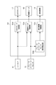
図1は、電動ブレーキ倍力装置1のシステム図である。電動ブレーキ倍力装置1は、マスタシリンダ2と、運転者がブレーキペダル7に入力したブレーキ操作力を、このマスタシリンダ2内のブレーキ液に伝達する第1ピストン8と、電動モータ40のブレーキアシスト力を伝達する第2ピストン9とを備えている。
[Configuration of electric brake booster]
FIG. 1 is a system diagram of the electric brake booster 1. The electric brake booster 1 includes a master cylinder 2, a first piston 8 that transmits a brake operation force input to the brake pedal 7 by the driver to the brake fluid in the master cylinder 2, and a brake assist of the electric motor 40. And a second piston 9 for transmitting force.

第1ピストン8は、ブレーキペダル7と接続するプッシュロッド80と、このプッシュロッド80と接続する主ピストン81とを有している。第2ピストン9は、電動モータ40と接続する電動モータ接続軸90と、ブレーキが作動していない状態において、電動モータ接続軸90のマスタシリンダ2側端面と当接するブーストピストン91とを有している。   The first piston 8 has a push rod 80 connected to the brake pedal 7 and a main piston 81 connected to the push rod 80. The second piston 9 has an electric motor connecting shaft 90 that is connected to the electric motor 40, and a boost piston 91 that is in contact with the end surface of the electric motor connecting shaft 90 on the master cylinder 2 side when the brake is not operating. Yes.

主ピストン81は、マスタシリンダ2側に小径部81aと、プッシュロッド80側に大径部81bとを有している。電動モータ接続軸90およびブーストピストン91は中空部を有している。また、電動モータ接続軸90のブレーキペダル7側の外周は、ボール30を回転可能に保持している。   The main piston 81 has a small diameter portion 81a on the master cylinder 2 side and a large diameter portion 81b on the push rod 80 side. The electric motor connecting shaft 90 and the boost piston 91 have a hollow portion. Further, the outer periphery of the electric motor connecting shaft 90 on the brake pedal 7 side holds the ball 30 rotatably.

主ピストン81の小径部81aは、ブーストピストン91の内周の径よりも小径であり、ブーストピストン91の中空部内に位置している。主ピストン81の大径部81bは、ブーストピストン91の内周の径よりも大径であって、電動モータ接続軸90の内周の径よりも小径である。主ピストン81の大径部81bは、電動モータ接続軸90の中空部内に位置している。ブレーキが作動していない状態において、大径部81bのマスタシリンダ2側の端面81cと、ブーストピストン91のブレーキペダル7側の端面91aとは軸方向に離間して位置している。これにより、自動ブレーキ作動時には、ブーストピストン91のみが移動し、主ピストン81、ブレーキペダル7が移動しないようにしている。   The small diameter portion 81 a of the main piston 81 is smaller in diameter than the inner peripheral diameter of the boost piston 91 and is located in the hollow portion of the boost piston 91. The large diameter portion 81 b of the main piston 81 is larger in diameter than the inner peripheral diameter of the boost piston 91 and smaller in diameter than the inner peripheral diameter of the electric motor connection shaft 90. The large diameter portion 81 b of the main piston 81 is located in the hollow portion of the electric motor connection shaft 90. In a state where the brake is not operated, the end surface 81c on the master cylinder 2 side of the large diameter portion 81b and the end surface 91a on the brake pedal 7 side of the boost piston 91 are positioned apart from each other in the axial direction. Thereby, at the time of an automatic brake operation, only the boost piston 91 moves and the main piston 81 and the brake pedal 7 are prevented from moving.

マスタシリンダ2は、有底のシリンダ本体20とリザーバタンク21を有している。シリンダ本体20内の奥側は、プライマリピストンとしての主ピストン81、ブーストピストン91と対を成すセカンダリピストン6を、シリンダ本体20の内壁に対して摺動可能に収装している。   The master cylinder 2 has a bottomed cylinder body 20 and a reservoir tank 21. The inner side of the cylinder main body 20 accommodates a secondary piston 6 paired with a main piston 81 as a primary piston and a boost piston 91 so as to be slidable with respect to the inner wall of the cylinder main body 20.

主ピストン81、ブーストピストン91とセカンダリピストン6とは、シリンダ本体20内を2つの圧力室11,12に隔成している。主ピストン81、ブーストピストン91とセカンダリピストン6の移動に応じて、各圧力室11,12内に封じ込めているブレーキ液が油圧回路13を介して各ホイール14のホイールシリンダ15に移動する。   The main piston 81, the boost piston 91, and the secondary piston 6 separate the inside of the cylinder body 20 into two pressure chambers 11 and 12. In accordance with the movement of the main piston 81, boost piston 91 and secondary piston 6, the brake fluid contained in each pressure chamber 11, 12 moves to the wheel cylinder 15 of each wheel 14 via the hydraulic circuit 13.

電動モータ40は、中空のDCブラシレスモータであって、ハウジング5の内壁に固定したステータ40aと、内周側にボールねじ溝40cを有するロータ40bを備えている。またレゾルバ41を設け、電動モータ40の回転位置を検出している。   The electric motor 40 is a hollow DC brushless motor, and includes a stator 40a fixed to the inner wall of the housing 5 and a rotor 40b having a ball screw groove 40c on the inner peripheral side. A resolver 41 is provided to detect the rotational position of the electric motor 40.

電動モータ接続軸90、ロータ40b、ボール30によりボールねじ機構3を形成している。ボールねじ機構3は、電動モータ40が駆動すると、ロータ40bの回転力をボール30を介して電動モータ接続軸90に軸方向の推力として伝達する。またボールねじ機構3は、電動モータ接続軸90に軸方向の推力が働くと、電動モータ接続軸90の推力をボール30を介してロータ40bに回転力として伝達する。   The ball screw mechanism 3 is formed by the electric motor connecting shaft 90, the rotor 40b, and the ball 30. When the electric motor 40 is driven, the ball screw mechanism 3 transmits the rotational force of the rotor 40b to the electric motor connecting shaft 90 via the balls 30 as axial thrust. In addition, the ball screw mechanism 3 transmits the thrust of the electric motor connection shaft 90 as a rotational force to the rotor 40b via the ball 30 when an axial thrust acts on the electric motor connection shaft 90.

主ピストン81と電動モータ接続軸90との間に、連結機構16を有している。この連結機構16は、第1ピストン8と第2ピストン9とを相対移動可能にする解放状態と、一体移動可能にする連結状態とに切り替えることができる。   A coupling mechanism 16 is provided between the main piston 81 and the electric motor connecting shaft 90. The coupling mechanism 16 can be switched between a released state in which the first piston 8 and the second piston 9 can be moved relative to each other and a connected state in which the first piston 8 and the second piston 9 can be moved together.

油圧回路13には、VDCポンプ17を接続している。このVDCポンプ17は、通常は、ヴィークルダイナミックコントロール(Vehicle Dynamics Control:以下、VDC)を行うときに、マスタシリンダ2とは別にブレーキ液圧を発生させるポンプである。   A VDC pump 17 is connected to the hydraulic circuit 13. The VDC pump 17 is a pump that normally generates brake fluid pressure separately from the master cylinder 2 when performing vehicle dynamics control (hereinafter referred to as VDC).

電動モータ40、連結機構16、VDCポンプ17は、コントロールユニット50によって制御する。このコントロールユニット50は、ブレーキストロークセンサ10からブレーキペダル7のストローク情報と、レゾルバ41から電動モータ40の回転位置情報とを入力し、これらの情報から各装置に指令信号を出力する。   The electric motor 40, the coupling mechanism 16, and the VDC pump 17 are controlled by the control unit 50. The control unit 50 inputs the stroke information of the brake pedal 7 from the brake stroke sensor 10 and the rotational position information of the electric motor 40 from the resolver 41, and outputs a command signal to each device from these information.

図2は連結機構16の拡大図である。連結機構16は、ラッチ16aと、磁石16bと、コイル16cと、バネ16dとから構成している。
ラッチ16aは、電動モータ接続軸90に設けたラッチ溝90aに係合可能に形成している。バネ16dは、ラッチ16aをラッチ溝90aと係合する方向に付勢している。磁石16bは、ラッチ16aをラッチ溝90aから離間する位置に吸引している。
FIG. 2 is an enlarged view of the coupling mechanism 16. The coupling mechanism 16 includes a latch 16a, a magnet 16b, a coil 16c, and a spring 16d.
The latch 16a is formed to be engageable with a latch groove 90a provided in the electric motor connecting shaft 90. The spring 16d biases the latch 16a in a direction to engage with the latch groove 90a. The magnet 16b attracts the latch 16a to a position away from the latch groove 90a.

コイル16cの非通電時には、図2(a)に示すように、バネ16dによるラッチ16aへの付勢力に対して、磁石16bによるラッチ16aの吸引力を強く設定する。そのため、コイル16cの非通電時にはラッチ16aとラッチ溝90aとは非係合状態となる。   When the coil 16c is not energized, as shown in FIG. 2A, the attractive force of the latch 16a by the magnet 16b is set stronger than the urging force of the spring 16d to the latch 16a. Therefore, when the coil 16c is not energized, the latch 16a and the latch groove 90a are not engaged.

コイル16cは、通電すると磁石16bの磁力を打ち消す方向に磁力を発生する。コイル16cの通電時には、図2(b)にしめすように、磁石16bがラッチ16aを吸引する力が低下し、バネ16dによるラッチ16aへの付勢力に対して、磁石16bによるラッチ16aの吸引力を弱くなるように設定している。そのため、コイル16cの通電時にはラッチ16aとラッチ溝90aとは係合状態となる。   When energized, the coil 16c generates a magnetic force in a direction that cancels the magnetic force of the magnet 16b. When the coil 16c is energized, as shown in FIG. 2B, the force of the magnet 16b attracting the latch 16a decreases, and the attracting force of the latch 16a by the magnet 16b against the biasing force of the spring 16d to the latch 16a. Is set to weaken. Therefore, the latch 16a and the latch groove 90a are engaged when the coil 16c is energized.

図3はコントロールユニット50の制御ブロック図である。コントロールユニット50は、電動モータ制御部50aと、ブレーキストロークセンサ異常検出部50bと、連結機構制御部50cと、VDCポンプ制御部50dとを有する。   FIG. 3 is a control block diagram of the control unit 50. The control unit 50 includes an electric motor control unit 50a, a brake stroke sensor abnormality detection unit 50b, a coupling mechanism control unit 50c, and a VDC pump control unit 50d.

電動モータ制御部50aは、ブレーキストロークセンサ10からブレーキストローク情報とレゾルバ41から電動モータ40の回転位置情報を入力する。このブレーキストローク情報と電動モータ40の回転位置情報に基づいて電動モータ40の指令信号を演算し、演算した指令信号を電動モータ40に出力する。   The electric motor control unit 50 a inputs brake stroke information from the brake stroke sensor 10 and rotational position information of the electric motor 40 from the resolver 41. A command signal of the electric motor 40 is calculated based on the brake stroke information and the rotational position information of the electric motor 40, and the calculated command signal is output to the electric motor 40.

ブレーキストロークセンサ異常検出部50bは、ブレーキストロークセンサ10のセンサ値を入力する。そして、ブレーキストロークセンサ10の異常検出を行い、この検出結果を連結機構制御部50cに出力する。なお、異常検出の具体例としては、例えば、センサ信号の上張り付き検知や、下張り付き検知、もしくは、他のセンサとの整合性判断によって実行されるものであり、特に限定しない。   The brake stroke sensor abnormality detection unit 50b inputs the sensor value of the brake stroke sensor 10. And abnormality detection of the brake stroke sensor 10 is performed, and this detection result is output to the connection mechanism control part 50c. Note that specific examples of abnormality detection are executed by, for example, detection of an upper sticking of a sensor signal, detection of an under sticking, or determination of consistency with other sensors, and are not particularly limited.

連結機構制御部50cは、ブレーキストロークセンサ異常検出部50bの検出結果を入力する。ブレーキストロークセンサ10が異常であるときには、連結機構16を連結する指令信号を連結機構16に出力する。   The connection mechanism control unit 50c inputs the detection result of the brake stroke sensor abnormality detection unit 50b. When the brake stroke sensor 10 is abnormal, a command signal for coupling the coupling mechanism 16 is output to the coupling mechanism 16.

VDCポンプ制御部50dは、レゾルバ41から電動モータ40の回転位置情報を入力する。この回転位置情報に基づいてVDCポンプの指令信号を演算し、演算した指令信号をVDCポンプ17に出力する。   The VDC pump control unit 50 d inputs rotational position information of the electric motor 40 from the resolver 41. Based on this rotational position information, a command signal for the VDC pump is calculated, and the calculated command signal is output to the VDC pump 17.

[電動ブレーキ倍力制御処理]
次に、コントロールユニット50の制御処理の流れについて説明する。図4は、コントロールユニット50の制御処理の流れを示すフローチャートである。
[Electric brake boost control process]
Next, the flow of control processing of the control unit 50 will be described. FIG. 4 is a flowchart showing the flow of control processing of the control unit 50.

ステップS1では、ブレーキストロークセンサ10からブレーキストローク情報を入力して、ステップS2へ移行する。
ステップS2では、レゾルバ41から電動モータ40の回転位置情報を入力してステップS3へ移行する。
In step S1, brake stroke information is input from the brake stroke sensor 10, and the process proceeds to step S2.
In step S2, the rotational position information of the electric motor 40 is input from the resolver 41, and the process proceeds to step S3.

ステップS3では、ブレーキストローク情報と電動モータ40の回転位置情報とに基づいて電動モータ40を駆動する指令信号を演算して、ステップS4へ移行する。
ステップS4では、電動モータ40に指令信号を出力して、ステップS5へ移行する。
ステップS5では、ブレーキストロークセンサ10の異常判定を行い、ステップS6へ移行する。
In step S3, a command signal for driving the electric motor 40 is calculated based on the brake stroke information and the rotational position information of the electric motor 40, and the process proceeds to step S4.
In step S4, a command signal is output to the electric motor 40, and the process proceeds to step S5.
In step S5, abnormality determination of the brake stroke sensor 10 is performed, and the process proceeds to step S6.

ステップS6では、ブレーキストロークセンサ10に異常が発生しているか否かを判断し、異常が発生している場合にはステップS7へ移行し、異常が発生していない場合にはリターンへ移行する。
ステップS7では、連結機構16に連結を行う指令信号を出力して、ステップS8へ移行する。
In step S6, it is determined whether or not an abnormality has occurred in the brake stroke sensor 10. If an abnormality has occurred, the process proceeds to step S7, and if no abnormality has occurred, the process proceeds to return.
In step S7, a command signal for coupling to the coupling mechanism 16 is output, and the process proceeds to step S8.

ステップS8では、レゾルバ41から電動モータ40の回転位置情報を入力して、ステップS9へ移行する。
ステップS9では、電動モータ40の回転位置情報に基づいて、VDCポンプ17を駆動する指令信号を演算して、ステップS10へ移行する。
ステップS10では、VDCポンプ17に指令信号を出力して、リターンへ移行する。
In step S8, the rotational position information of the electric motor 40 is input from the resolver 41, and the process proceeds to step S9.
In step S9, a command signal for driving the VDC pump 17 is calculated based on the rotational position information of the electric motor 40, and the process proceeds to step S10.
In step S10, a command signal is output to the VDC pump 17, and the process proceeds to return.

[電動ブレーキ倍力制御作用]
次に、電動ブレーキ倍力装置1の制御の作用について説明する。
[Electric brake boost control]
Next, the control action of the electric brake booster 1 will be described.

(ブレーキストロークセンサ正常時)
ブレーキストロークセンサ10が正常であるときには、図4のフローチャートにおいて、ステップS1→ステップS2→ステップS3→ステップS4→ステップS5→ステップS6→リターンへと移行する。
(When brake stroke sensor is normal)
When the brake stroke sensor 10 is normal, in the flowchart of FIG. 4, the process proceeds from step S1, step S2, step S3, step S4, step S5, step S6, and return.

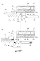
図5は、ブレーキストロークセンサ10が正常であるときの電動ブレーキ倍力装置1の動作を示す図である。図5は、第1ピストン8、第2ピストン9および電動モータ40の部分の拡大図であって、軸線に対して上方のみを記載している。図5(a)はブレーキペダル7がストロークする前の状態を示し、図5(b)はブレーキペダル7がストロークした状態を示す。   FIG. 5 is a diagram illustrating the operation of the electric brake booster 1 when the brake stroke sensor 10 is normal. FIG. 5 is an enlarged view of portions of the first piston 8, the second piston 9, and the electric motor 40, and shows only the upper part with respect to the axis. FIG. 5A shows a state before the brake pedal 7 is stroked, and FIG. 5B shows a state where the brake pedal 7 is stroked.

ステップS3において、ブレーキストロークセンサ10からのブレーキストローク情報とレゾルバ41からの電動モータ40の回転位置情報とに基づいて電動モータ40を駆動する。そのため、図5(b)に示すように電動モータ40から電動モータ接続軸90へ推力を伝達し、電動モータ接続軸90がブーストピストン91を押圧する。これにより、運転者のブレーキ操作力に対してアシスト力を付与することができる。   In step S <b> 3, the electric motor 40 is driven based on the brake stroke information from the brake stroke sensor 10 and the rotational position information of the electric motor 40 from the resolver 41. Therefore, as shown in FIG. 5B, thrust is transmitted from the electric motor 40 to the electric motor connection shaft 90, and the electric motor connection shaft 90 presses the boost piston 91. Thereby, assist force can be provided with respect to a driver | operator's brake operation force.

(ブレーキストロークセンサ異常時)
ブレーキストロークセンサ10が異常であるときの電動ブレーキ倍力装置1の動作とホイールシリンダ15のブレーキ液圧について説明する。
(When the brake stroke sensor is abnormal)
The operation of the electric brake booster 1 and the brake fluid pressure of the wheel cylinder 15 when the brake stroke sensor 10 is abnormal will be described.

図6は、連結機構16を有しない電動ブレーキ倍力装置1の動作を示す図である。図6は、第1ピストン8、第2ピストン9および電動モータ40の部分の拡大図であって、軸線に対して上方のみを記載している。図6(a)はブレーキペダル7がストロークする前の状態を示し、図6(b)はブレーキペダル7がストロークした状態を示す。   FIG. 6 is a diagram illustrating the operation of the electric brake booster 1 that does not include the coupling mechanism 16. FIG. 6 is an enlarged view of portions of the first piston 8, the second piston 9, and the electric motor 40, and shows only the upper part with respect to the axis. 6A shows a state before the brake pedal 7 is stroked, and FIG. 6B shows a state where the brake pedal 7 is stroked.

ブレーキストロークセンサ10が異常であるときには、電動モータ40を駆動する指令信号を演算することができない。よって、電動モータ40への指令信号が出力されず、電動モータ40は駆動しない。電動モータ40から電動モータ接続軸90へ推力が伝達されず、電動モータ接続軸90がブーストピストン91を押圧できないため、ブーストピストン91は移動しない。   When the brake stroke sensor 10 is abnormal, the command signal for driving the electric motor 40 cannot be calculated. Therefore, the command signal to the electric motor 40 is not output, and the electric motor 40 is not driven. Since the thrust is not transmitted from the electric motor 40 to the electric motor connecting shaft 90 and the electric motor connecting shaft 90 cannot press the boost piston 91, the boost piston 91 does not move.

主ピストン81がブーストピストン91側に相対移動すると、主ピストン81の端面81cとブーストピストン91の端面91aとが当接し、主ピストン81とブーストピストン91を一体移動することが可能である。   When the main piston 81 moves relative to the boost piston 91, the end surface 81c of the main piston 81 and the end surface 91a of the boost piston 91 come into contact with each other, and the main piston 81 and the boost piston 91 can be moved together.

ここで、図6(a)に示すようにブレーキが作動していない状態において、主ピストン81の端面81cとブーストピストン91の端面91aとは軸方向に離間して配置している。そのため、図6(b)に示すように、主ピストン81の端面81cとブーストピストン91の端面91aとが当接するまでブーストピストン91は移動しない。すなわち主ピストン81のみが移動している間は、ホイールシリンダ15側に十分なブレーキ液を供給することができず、ブレーキ液圧が立ち上がらない。   Here, as shown in FIG. 6A, the end surface 81c of the main piston 81 and the end surface 91a of the boost piston 91 are arranged apart from each other in the axial direction when the brake is not operating. Therefore, as shown in FIG. 6B, the boost piston 91 does not move until the end surface 81c of the main piston 81 and the end surface 91a of the boost piston 91 come into contact with each other. That is, while only the main piston 81 is moving, sufficient brake fluid cannot be supplied to the wheel cylinder 15 side, and the brake fluid pressure does not rise.

したがって、ブレーキストロークセンサ10が正常であるときに比べて異常であるときには、ブレーキ液圧の立ち上がりが遅くなるといった問題があった。
また、電動モータ40が駆動しないため、ブレーキアシスト力を付与することができないといった問題があった。
Therefore, when the brake stroke sensor 10 is abnormal as compared to when it is normal, there is a problem that the rise of the brake fluid pressure is delayed.
Further, since the electric motor 40 is not driven, there is a problem that the brake assist force cannot be applied.

そこで実施例1では、ブレーキ液圧の立ち上がりが遅くなるという問題に対して、連結機構16を設け、ブレーキストロークセンサ10に異常が発生している場合には、連結機構16によって第1ピストン8と第2ピストン9とを一体移動可能に連結するようにした。   Therefore, in the first embodiment, the connection mechanism 16 is provided for the problem that the rise of the brake fluid pressure is delayed. When an abnormality occurs in the brake stroke sensor 10, the connection mechanism 16 and the first piston 8 are connected. The second piston 9 is connected to be movable together.

また実施例1では、ブレーキアシスト力を付与することができないという問題に対して、電動モータ40のレゾルバ41が検出する電動モータ40の回転位置情報に基づいて、VDCポンプ17を駆動してブレーキ液圧を発生させるようにした。   Further, in the first embodiment, in response to the problem that the brake assist force cannot be applied, the VDC pump 17 is driven and brake fluid is driven based on the rotational position information of the electric motor 40 detected by the resolver 41 of the electric motor 40. Pressure was generated.

ブレーキストロークセンサ10に異常が発生している場合には、図4のフローチャートにおいて、ステップS1→ステップS2→ステップS3→ステップS4→ステップS5→ステップS6→ステップS7へと移行する。   If an abnormality has occurred in the brake stroke sensor 10, the process proceeds from step S1, step S2, step S3, step S4, step S5, step S6, and step S7 in the flowchart of FIG.

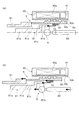
図7は、実施例1の電動ブレーキ倍力装置1の動作を示す図である。図7は、第1ピストン8、第2ピストン9および電動モータ40の部分の拡大図であって、軸線に対して上方のみを記載している。図7(a)はブレーキペダル7がストロークする前の状態を示し、図7(b)はブレーキペダル7がストロークした状態を示す。   FIG. 7 is a diagram illustrating the operation of the electric brake booster 1 according to the first embodiment. FIG. 7 is an enlarged view of portions of the first piston 8, the second piston 9, and the electric motor 40, and shows only the upper part with respect to the axis. FIG. 7A shows a state before the brake pedal 7 is stroked, and FIG. 7B shows a state where the brake pedal 7 is stroked.

ステップS6において、ブレーキストロークセンサ10に異常が発生したと判断すると、図7(a)に示すようにステップS7において連結機構16を締結する。この状態でブレーキペダル7がストロークすると、図7(b)に示すように推力は、プッシュロッド80→主ピストン81→連結機構16→電動モータ接続軸90→ブーストピストン91の順で伝達し、第1ピストン8と第2ピストン9とは一体に移動する。   If it is determined in step S6 that an abnormality has occurred in the brake stroke sensor 10, the coupling mechanism 16 is fastened in step S7 as shown in FIG. When the brake pedal 7 strokes in this state, the thrust is transmitted in the order of push rod 80 → main piston 81 → coupling mechanism 16 → electric motor connecting shaft 90 → boost piston 91 as shown in FIG. The first piston 8 and the second piston 9 move together.

ステップS7に続いて、ステップS8→ステップS9→ステップS10→RETURNへと移行する。
ステップS7において、連結機構16を締結しているため、主ピストン81と電動モータ接続軸90とが一体に移動する。電動モータ40のロータ40b、電動モータ接続軸90およびボール30はボールねじ機構3を構成するため、主ピストン81から電動モータ接続軸90に推力が作用すると、ロータ40bは電動モータ接続軸90の移動に応じて回転する。そのとき、レゾルバ41は電動モータ40の回転位置を検出することができる。ステップS8で入力した電動モータ40の回転位置の変化量から、ブレーキペダル7のブレーキストローク量を求める。ここで求めたブレーキストローク量に応じて、ステップS9においてVDCポンプ17の指令信号を演算し、ステップS10においてVDCポンプ17へ指令信号を出力する。
Subsequent to step S7, the process proceeds from step S8 to step S9 to step S10 to RETURN.
In step S7, since the coupling mechanism 16 is fastened, the main piston 81 and the electric motor connecting shaft 90 move together. Since the rotor 40b, the electric motor connection shaft 90, and the ball 30 of the electric motor 40 constitute the ball screw mechanism 3, when the thrust acts on the electric motor connection shaft 90 from the main piston 81, the rotor 40b moves the electric motor connection shaft 90. Rotate according to. At that time, the resolver 41 can detect the rotational position of the electric motor 40. The brake stroke amount of the brake pedal 7 is obtained from the amount of change in the rotational position of the electric motor 40 input in step S8. According to the brake stroke amount obtained here, a command signal for the VDC pump 17 is calculated in step S9, and the command signal is output to the VDC pump 17 in step S10.

図8は、ホイールシリンダ15におけるブレーキ液圧の時間変化を示すタイムチャートである。図8の細実線は、ブレーキストロークセンサ10が正常なときのブレーキ液圧の時間変化を示す。図8の太実線は、ブレーキストロークセンサ10が異常であるときに、連結機構16を連結するとともに、VDCポンプ17を駆動したときのブレーキ液圧の時間変化を示す。図8の点線は、連結機構16を有しない電動ブレーキ倍力装置1において、ブレーキストロークセンサ10が異常であるときのブレーキ液圧の時間変化を示す。   FIG. 8 is a time chart showing the time change of the brake fluid pressure in the wheel cylinder 15. The thin solid line in FIG. 8 shows the change over time in the brake fluid pressure when the brake stroke sensor 10 is normal. The thick solid line in FIG. 8 shows the change over time in the brake fluid pressure when the connecting mechanism 16 is connected and the VDC pump 17 is driven when the brake stroke sensor 10 is abnormal. The dotted line in FIG. 8 shows the change over time in the brake fluid pressure when the brake stroke sensor 10 is abnormal in the electric brake booster 1 that does not have the coupling mechanism 16.

図8に示すように、連結機構16を有しない電動ブレーキ倍力装置1においては、ブレーキストロークセンサ10が異常であるときには、正常であるときに比べてブレーキ液圧の立ち上がりが遅れる。また、ブレーキストロークセンサ10が異常であるときには、電動モータ40が駆動しないため、アシスト力が作用せず、正常であるときに比べてブレーキ液圧が低くなる。   As shown in FIG. 8, in the electric brake booster 1 that does not have the coupling mechanism 16, when the brake stroke sensor 10 is abnormal, the rise of the brake hydraulic pressure is delayed compared to when it is normal. Further, when the brake stroke sensor 10 is abnormal, the electric motor 40 is not driven, so the assist force does not act, and the brake fluid pressure is lower than when it is normal.

これに対し、図8に示すように、実施例1の電動ブレーキ倍力装置1においては、ブレーキストロークセンサ10が異常であるときには、正常であるときと比べてもブレーキ液圧の立ち上がりは十分に早くすることができる。また、実施例1の電動ブレーキ倍力装置1においても、ブレーキストロークセンサ10が異常であるときには電動モータ40は駆動しないが、VDCポンプ17によってブレーキ液圧を発生させるために、正常であるときに比べても十分に高いブレーキ液圧を確保することができる。   On the other hand, as shown in FIG. 8, in the electric brake booster 1 of the first embodiment, when the brake stroke sensor 10 is abnormal, the brake fluid pressure rises sufficiently compared to when it is normal. Can be fast. Also in the electric brake booster 1 of the first embodiment, when the brake stroke sensor 10 is abnormal, the electric motor 40 is not driven, but since the brake fluid pressure is generated by the VDC pump 17, it is normal. Even if compared, a sufficiently high brake fluid pressure can be secured.

[実施例1の効果]
次に実施例1の効果について、以下に列記する。
[Effect of Example 1]
Next, effects of Example 1 are listed below.

(1)ブレーキペダル7に連結された第1ピストン8と、電動モータ40により推力を発生する第2ピストン9と、第1ピストン8および/または第2ピストン9の作動により液圧を発生させるマスタシリンダ2と、第1ピストン8と第2ピストン9とを一体移動可能に連結可能な連結機構16と、所定の条件のときに連結機構16を連結する連結機構制御部50cと、を設けた。   (1) The first piston 8 connected to the brake pedal 7, the second piston 9 that generates thrust by the electric motor 40, and the master that generates hydraulic pressure by the operation of the first piston 8 and / or the second piston 9. The cylinder 2, the coupling mechanism 16 capable of coupling the first piston 8 and the second piston 9 so as to be integrally movable, and the coupling mechanism control unit 50c for coupling the coupling mechanism 16 under a predetermined condition are provided.

よって、第1ピストン8と第2ピストン9とは一体移動することが可能となり、主ピストン81とブーストピストン91によって、ホイールシリンダ15側にブレーキ液を供給することが可能となる。したがって、主ピストン81のみによるブレーキ液の供給に比べて、主ピストン81とブーストピストン91によるブレーキ液圧の供給は多くなり、ブレーキ液圧の立ち上がりを、主ピストン81のみが移動する場合に比べて早くすることができる。   Therefore, the first piston 8 and the second piston 9 can move together, and the brake fluid can be supplied to the wheel cylinder 15 side by the main piston 81 and the boost piston 91. Therefore, the supply of brake fluid pressure by the main piston 81 and the boost piston 91 is larger than the supply of brake fluid only by the main piston 81, and the rise of the brake fluid pressure is higher than when only the main piston 81 moves. Can be fast.

(2)ブレーキペダル7のストローク量を検出するブレーキストロークセンサ10と、ストローク量に応じて、電動モータ40を制御する電動モータ制御部50aと、ブレーキストロークセンサ10の異常状態を検出するブレーキストロークセンサ異常検出部50bと、を設け、連結機構制御部50cは、ブレーキストロークセンサ10の異常状態を検出したときに連結機構16を連結するようにした。   (2) A brake stroke sensor 10 that detects the stroke amount of the brake pedal 7, an electric motor control unit 50a that controls the electric motor 40 in accordance with the stroke amount, and a brake stroke sensor that detects an abnormal state of the brake stroke sensor 10. An abnormality detection unit 50b, and the connection mechanism control unit 50c connects the connection mechanism 16 when an abnormal state of the brake stroke sensor 10 is detected.

よって、ブレーキストロークセンサ10が異常状態であって、電動モータ40が駆動しないときであっても、第1ピストン8と第2ピストン9とを一体移動することが可能となる。したがって、主ピストン81とブーストピストン91によって、ホイールシリンダ15側にブレーキ液を供給することが可能となる。そのため、主ピストン81のみによるブレーキ液の供給に比べて、主ピストン81とブーストピストン91によるブレーキ液圧の供給は多くなり、ブレーキ液圧の立ち上がりを、電動モータ40が駆動するときと同程度に早くすることができる。   Therefore, even when the brake stroke sensor 10 is in an abnormal state and the electric motor 40 is not driven, the first piston 8 and the second piston 9 can be moved integrally. Accordingly, the brake fluid can be supplied to the wheel cylinder 15 side by the main piston 81 and the boost piston 91. Therefore, the supply of brake fluid pressure by the main piston 81 and the boost piston 91 is larger than the supply of brake fluid only by the main piston 81, and the rise of the brake fluid pressure is about the same as when the electric motor 40 is driven. Can be fast.

(3)第1ピストン8は、ブレーキペダル7からの操作力を入力するプッシュロッド80と、プッシュロッド80に連結する主ピストン81とを有し、第2ピストン9は、電動モータ40と接続する電動モータ接続軸90と、電動モータ接続軸90から推力を伝達されるブーストピストン91とを有し、連結機構16は、主ピストン81と電動モータ接続軸90との間を連結可能とした。   (3) The first piston 8 has a push rod 80 for inputting an operating force from the brake pedal 7 and a main piston 81 coupled to the push rod 80, and the second piston 9 is connected to the electric motor 40. An electric motor connection shaft 90 and a boost piston 91 to which thrust is transmitted from the electric motor connection shaft 90 are provided, and the coupling mechanism 16 can connect the main piston 81 and the electric motor connection shaft 90.

よって、主ピストン81から電動モータ接続軸90を介してブーストピストン91に推力を伝達することが可能となる。そのため、主ピストン81とブーストピストン91によって、ホイールシリンダ15側にブレーキ液を供給することが可能となり、ブレーキ液圧の立ち上がりを電動モータ40が駆動するときと同程度に早くすることができる。   Therefore, it becomes possible to transmit thrust from the main piston 81 to the boost piston 91 via the electric motor connecting shaft 90. Therefore, the brake fluid can be supplied to the wheel cylinder 15 side by the main piston 81 and the boost piston 91, and the rise of the brake fluid pressure can be made as fast as when the electric motor 40 is driven.

(4)電動モータ40と電動モータ接続軸90との間に、電動モータ接続軸90に作用する力を電動モータ40へ伝達可能なボールねじ機構3と、電動モータ40の回転位置を検出するレゾルバ40と、ブレーキ液圧を発生するVDCポンプ17と、異常状態を検出したときは、電動モータ40の回転位置に応じてVDCポンプ17を駆動するVDCポンプ制御部50dとを設けた。   (4) Between the electric motor 40 and the electric motor connecting shaft 90, a ball screw mechanism 3 capable of transmitting the force acting on the electric motor connecting shaft 90 to the electric motor 40, and a resolver for detecting the rotational position of the electric motor 40. 40, a VDC pump 17 that generates brake fluid pressure, and a VDC pump controller 50d that drives the VDC pump 17 according to the rotational position of the electric motor 40 when an abnormal state is detected.

よって、運転者の操作力によるマスタシリンダ2で発生するブレーキ液圧に加えて、VDCポンプ17で発生するブレーキ液圧をホイールシリンダ15に圧送することが可能となる。そのため、ホイールシリンダ15のブレーキ液圧を電動モータ40が駆動するときと同程度に高くすることができる。   Therefore, in addition to the brake hydraulic pressure generated in the master cylinder 2 by the driver's operating force, the brake hydraulic pressure generated in the VDC pump 17 can be pumped to the wheel cylinder 15. Therefore, the brake hydraulic pressure of the wheel cylinder 15 can be made as high as when the electric motor 40 is driven.

(5)マスタシリンダ2の、ブレーキペダル7に連結された第1ピストン8と、電動モータ40により推力を発生する第2ピストン8とを所定の条件のときに一体移動するようにした。   (5) The first piston 8 connected to the brake pedal 7 of the master cylinder 2 and the second piston 8 that generates thrust by the electric motor 40 are integrally moved under a predetermined condition.

よって、ブレーキストロークセンサ10が異常である場合に電動モータ40が駆動しないときであっても、第1ピストン8と第2ピストン9とは一体移動することが可能となる。そのため、主ピストン81とブーストピストン91によって、ホイールシリンダ15側にブレーキ液を供給することが可能となる。したがって、主ピストン81のみによるブレーキ液の供給に比べて、主ピストン81とブーストピストン91によるブレーキ液圧の供給は多くなり、ブレーキ液圧の立ち上がりを電動モータ40が駆動するときと同程度に早くすることができる。   Therefore, even when the electric motor 40 is not driven when the brake stroke sensor 10 is abnormal, the first piston 8 and the second piston 9 can move together. Therefore, the brake fluid can be supplied to the wheel cylinder 15 side by the main piston 81 and the boost piston 91. Therefore, compared with the supply of the brake fluid only by the main piston 81, the supply of the brake fluid pressure by the main piston 81 and the boost piston 91 is increased, and the rise of the brake fluid pressure is as fast as when the electric motor 40 is driven. can do.

次に、実施例2の電動ブレーキ倍力装置1について説明する。以下では、実施例1と同じ構成については、同一の符号を付して説明を省略する。   Next, the electric brake booster 1 according to the second embodiment will be described. In the following, the same components as those in the first embodiment are denoted by the same reference numerals, and description thereof is omitted.

[電動ブレーキ倍力装置の構成]
図9は、実施例2の電動ブレーキ倍力装置1のシステム図である。連結機構16は、実施例1では主ピストン81と電動モータ接続軸90とを連結していたが、実施例2では連結機構16は、主ピストン81とブーストピストン91とを連結するようにした。また、ブレーキストロークセンサ10が異常であるときには、実施例1ではレゾルバ41からの電動モータ40の回転位置情報に応じてVDCポンプ17を制御していたが、実施例2ではマスタシリンダ圧センサ22からのマスタシリンダ圧情報に応じてVDCポンプ17を制御するようにした。
[Configuration of electric brake booster]
FIG. 9 is a system diagram of the electric brake booster 1 according to the second embodiment. The connection mechanism 16 connects the main piston 81 and the electric motor connecting shaft 90 in the first embodiment, but in the second embodiment, the connection mechanism 16 connects the main piston 81 and the boost piston 91. When the brake stroke sensor 10 is abnormal, the VDC pump 17 is controlled according to the rotational position information of the electric motor 40 from the resolver 41 in the first embodiment, but from the master cylinder pressure sensor 22 in the second embodiment. The VDC pump 17 is controlled according to the master cylinder pressure information.

主ピストン81とブーストピストン91との間に、連結機構16を有している。この連結機構16は、主ピストン81とブーストピストン91とを相対移動可能にする解放状態と、一体移動可能にする連結状態とを切り替えることができる。
また、マスタシリンダ2は、マスタシリンダ圧を検出するマスタシリンダ圧センサ22を有している。
A connecting mechanism 16 is provided between the main piston 81 and the boost piston 91. The coupling mechanism 16 can switch between a released state in which the main piston 81 and the boost piston 91 can be moved relative to each other and a connected state in which the main piston 81 and the boost piston 91 can be moved together.
The master cylinder 2 has a master cylinder pressure sensor 22 that detects the master cylinder pressure.

図10はコントロールユニット50の制御ブロック図である。コントロールユニット50は、電動モータ制御部50aと、ブレーキストロークセンサ異常検出部50bと、連結機構制御部50cと、VDCポンプ制御部50dとを有している。   FIG. 10 is a control block diagram of the control unit 50. The control unit 50 includes an electric motor control unit 50a, a brake stroke sensor abnormality detection unit 50b, a coupling mechanism control unit 50c, and a VDC pump control unit 50d.

電動モータ制御部50aは、ブレーキストロークセンサ10からブレーキストローク情報とレゾルバ41から電動モータ40の回転位置情報を入力する。これらの情報に基づいて電動モータ40の指令信号を演算し、演算した指令信号を電動モータ40に出力する。   The electric motor control unit 50 a inputs brake stroke information from the brake stroke sensor 10 and rotational position information of the electric motor 40 from the resolver 41. Based on these pieces of information, a command signal for the electric motor 40 is calculated, and the calculated command signal is output to the electric motor 40.

ブレーキストロークセンサ異常検出部50bは、ブレーキストロークセンサ10のセンサ値を入力する。そして、ブレーキストロークセンサ10の異常検出を行い、この検出結果を連結機構制御部50cに出力する。なお、異常検出の具体例としては、例えば、センサ信号の上張り付き検知や、下張り付き検知、もしくは、他のセンサとの整合性判断によって実行されるものであり、特に限定しない。   The brake stroke sensor abnormality detection unit 50b inputs the sensor value of the brake stroke sensor 10. And abnormality detection of the brake stroke sensor 10 is performed, and this detection result is output to the connection mechanism control part 50c. Note that specific examples of abnormality detection are executed by, for example, detection of an upper sticking of a sensor signal, detection of an under sticking, or determination of consistency with other sensors, and are not particularly limited.

連結機構制御部50cは、ブレーキストロークセンサ異常検出部50bの検出結果を入力する。ブレーキストロークセンサ10が異常であるときには、連結機構16を連結するように指令信号を出力する。   The connection mechanism control unit 50c inputs the detection result of the brake stroke sensor abnormality detection unit 50b. When the brake stroke sensor 10 is abnormal, a command signal is output to connect the connecting mechanism 16.

VDCポンプ制御部50dは、マスタシリンダ圧センサ22からマスタシリンダ圧情報を入力する。このマスタシリンダ圧情報に基づいてVDCポンプの指令信号を演算し、演算した指令信号をVDCポンプ17に出力する。   The VDC pump control unit 50 d inputs master cylinder pressure information from the master cylinder pressure sensor 22. A command signal for the VDC pump is calculated based on the master cylinder pressure information, and the calculated command signal is output to the VDC pump 17.

[電動ブレーキ倍力制御処理]
次に、コントロールユニット50の制御処理の流れについて説明する。図11は、コントロールユニット50の制御処理の流れを示すフローチャートである。
[Electric brake boost control process]
Next, the flow of control processing of the control unit 50 will be described. FIG. 11 is a flowchart showing the flow of control processing of the control unit 50.

ステップS11では、ブレーキストロークセンサ10からブレーキストローク情報を入力して、ステップS12へ移行する。
ステップS12では、レゾルバ41から電動モータ40の回転位置情報を入力してステップS13へ移行する。
In step S11, brake stroke information is input from the brake stroke sensor 10, and the process proceeds to step S12.
In step S12, the rotational position information of the electric motor 40 is input from the resolver 41, and the process proceeds to step S13.

ステップS13では、ブレーキストローク情報と電動モータ40の回転位置情報とに基づいて電動モータ40を駆動する指令信号を演算して、ステップS14へ移行する。
ステップS14では、電動モータ40に指令信号を出力して、ステップS15へ移行する。
ステップS15では、ブレーキストロークセンサ10の異常判定を行い、ステップS16へ移行する。
In step S13, a command signal for driving the electric motor 40 is calculated based on the brake stroke information and the rotational position information of the electric motor 40, and the process proceeds to step S14.
In step S14, a command signal is output to the electric motor 40, and the process proceeds to step S15.
In step S15, abnormality determination of the brake stroke sensor 10 is performed, and the process proceeds to step S16.

ステップS16では、ブレーキストロークセンサ10に異常が発生しているか否かを判断し、異常が発生している場合にはステップS17へ移行し、異常が発生していない場合にはリターンへ移行する。
ステップS17では、連結機構16に連結を行う指令信号を出力して、ステップS18へ移行する。
In step S16, it is determined whether or not an abnormality has occurred in the brake stroke sensor 10. If an abnormality has occurred, the process proceeds to step S17, and if no abnormality has occurred, the process proceeds to return.
In step S17, a command signal for coupling to the coupling mechanism 16 is output, and the process proceeds to step S18.

ステップS18では、マスタシリンダ圧センサ22からマスタシリンダ圧情報を入力して、ステップS19へ移行する。
ステップS19では、マスタシリンダ圧情報に基づいて、VDCポンプ17を駆動する指令信号を演算して、ステップS20へ移行する。
ステップS20では、VDCポンプ17に指令信号を出力して、リターンへ移行する。
In step S18, master cylinder pressure information is input from the master cylinder pressure sensor 22, and the process proceeds to step S19.
In step S19, a command signal for driving the VDC pump 17 is calculated based on the master cylinder pressure information, and the process proceeds to step S20.
In step S20, a command signal is output to the VDC pump 17, and the process proceeds to return.

[電動ブレーキ倍力制御作用]
次に、電動ブレーキ倍力装置1の制御の作用について説明する。
[Electric brake boost control]
Next, the control action of the electric brake booster 1 will be described.

(ブレーキストロークセンサ正常時)
ブレーキストロークセンサ10が正常であるときには、図11のフローチャートにおいて、ステップS11→ステップS12→ステップS13→ステップS14→ステップS15→ステップS16→リターンへと移行する。
(When brake stroke sensor is normal)
When the brake stroke sensor 10 is normal, the process proceeds from step S11 to step S12, step S13, step S14, step S15, step S16, and return in the flowchart of FIG.

ステップS13において、ブレーキストロークセンサ10からのブレーキストローク情報とレゾルバ41からの電動モータ40の回転位置情報に基づいて電動モータ40を駆動する。そのため、電動モータ40から電動モータ接続軸90へ推力を伝達し、電動モータ接続軸90がブーストピストン91を押圧する。これにより、運転者のブレーキ操作力に対してアシスト力を付与することができる。   In step S <b> 13, the electric motor 40 is driven based on the brake stroke information from the brake stroke sensor 10 and the rotational position information of the electric motor 40 from the resolver 41. Therefore, thrust is transmitted from the electric motor 40 to the electric motor connecting shaft 90, and the electric motor connecting shaft 90 presses the boost piston 91. Thereby, assist force can be provided with respect to a driver | operator's brake operation force.

(ブレーキストロークセンサ異常時)
実施例1では説明したように、ブレーキストロークセンサ10が正常であるときに比べて異常であるときには、ブレーキ液圧の立ち上がりが遅くなるといった問題があった。
また、電動モータ40が駆動しないため、ブレーキアシスト力を付与することができないといった問題があった。
(When the brake stroke sensor is abnormal)
As described in the first embodiment, when the brake stroke sensor 10 is abnormal as compared with the normal state, there is a problem that the rise of the brake hydraulic pressure is delayed.
Further, since the electric motor 40 is not driven, there is a problem that the brake assist force cannot be applied.

そこで実施例2では、ブレーキ液圧の立ち上がりが遅くなるという問題に対して、連結機構16を設け、ブレーキストロークセンサ10に異常が発生している場合には、連結機構16によって第1ピストン8と第2ピストン9のブーストピストン91とを一体移動可能に連結するようにした。   Therefore, in the second embodiment, the connection mechanism 16 is provided for the problem that the rise of the brake fluid pressure is delayed. When an abnormality occurs in the brake stroke sensor 10, the connection mechanism 16 and the first piston 8 are connected. The boost piston 91 of the second piston 9 is connected to be movable together.

また実施例2では、ブレーキアシスト力を付与することができないという問題に対して、マスタシリンダ圧センサ22が検出するマスタシリンダ圧情報に基づいて、VDCポンプ17を駆動してブレーキ液圧を発生させるようにした。   In the second embodiment, the brake fluid pressure is generated by driving the VDC pump 17 based on the master cylinder pressure information detected by the master cylinder pressure sensor 22 for the problem that the brake assist force cannot be applied. I did it.

ブレーキストロークセンサ10に異常が発生している場合には、図11のフローチャートにおいて、ステップS11→ステップS12→ステップS13→ステップS14→ステップS15→ステップS16→ステップS17へと移行する。   If an abnormality has occurred in the brake stroke sensor 10, the process proceeds to step S11 → step S12 → step S13 → step S14 → step S15 → step S16 → step S17 in the flowchart of FIG.

図12は、実施例2の電動ブレーキ倍力装置1の動作を示す図である。図12は、第1ピストン8、第2ピストン9および電動モータ40の部分の拡大図であって、軸線に対して上方のみを記載している。図12(a)はブレーキペダル7がストロークする前の状態を示し、図12(b)はブレーキペダル7がストロークした状態を示す。   FIG. 12 is a diagram illustrating the operation of the electric brake booster 1 according to the second embodiment. FIG. 12 is an enlarged view of portions of the first piston 8, the second piston 9, and the electric motor 40, and shows only the upper part with respect to the axis. FIG. 12A shows a state before the brake pedal 7 is stroked, and FIG. 12B shows a state where the brake pedal 7 is stroked.

ステップS16において、ブレーキストロークセンサ10に異常が発生したと判断すると、ステップS17において図12(a)に示すように連結機構16を締結する。この状態でブレーキペダル7がストロークすると、図12(b)に示すように推力は、プッシュロッド80→主ピストン81→連結機構16→ブーストピストン91の順で伝達し、第1ピストン8とブーストピストン91とは一体に移動する。実施例2では、ブレーキペダル7からの推力は電動モータ接続軸90には伝達しないため、電動モータ接続軸90は移動しない。   If it is determined in step S16 that an abnormality has occurred in the brake stroke sensor 10, the coupling mechanism 16 is fastened in step S17 as shown in FIG. When the brake pedal 7 strokes in this state, the thrust is transmitted in the order of push rod 80 → main piston 81 → connecting mechanism 16 → boost piston 91 as shown in FIG. 91 moves together. In the second embodiment, since the thrust from the brake pedal 7 is not transmitted to the electric motor connecting shaft 90, the electric motor connecting shaft 90 does not move.

ステップS17に続いて、ステップS18→ステップS19→ステップS20→RETURNへと移行する。
ステップS17において、連結機構16を締結しているため、主ピストン81とブーストピストン91とが一体に移動する。主ピストン81とブーストピストン91が移動するとマスタシリンダ圧センサ22がマスタシリンダ圧を検出し、マスタシリンダ圧の変化量から、ブレーキペダル7のブレーキストローク量を求める。ここで求めたブレーキストローク量に応じて、ステップS19においてVDCポンプ17の指令信号を演算し、ステップS20においてVDCポンプ17へ指令信号を出力する。
Subsequent to step S17, the process proceeds from step S18 to step S19 to step S20 to RETURN.
In step S17, since the coupling mechanism 16 is fastened, the main piston 81 and the boost piston 91 move together. When the main piston 81 and the boost piston 91 move, the master cylinder pressure sensor 22 detects the master cylinder pressure, and obtains the brake stroke amount of the brake pedal 7 from the change amount of the master cylinder pressure. In step S19, a command signal for the VDC pump 17 is calculated according to the brake stroke amount obtained here, and the command signal is output to the VDC pump 17 in step S20.

これにより実施例2の電動ブレーキ倍力装置1においては、ブレーキストロークセンサ10が異常であるときには、正常であるときと比べてもブレーキ液圧の立ち上がりは十分に早くすることができる。また、実施例2の電動ブレーキ倍力装置1においても、ブレーキストロークセンサ10が異常であるときには電動モータ40は駆動しないが、VDCポンプ17によってブレーキ液圧を発生させるために、正常であるときに比べても十分に高いブレーキ液圧を確保することができる。   As a result, in the electric brake booster 1 of the second embodiment, when the brake stroke sensor 10 is abnormal, the rise of the brake hydraulic pressure can be made sufficiently faster than when it is normal. Also in the electric brake booster 1 of the second embodiment, the electric motor 40 is not driven when the brake stroke sensor 10 is abnormal, but when the brake stroke sensor 10 is normal because the brake fluid pressure is generated by the VDC pump 17. Even if compared, a sufficiently high brake fluid pressure can be secured.

また、実施例2では、主ピストン81とブーストピストン91とを連結して一体に移動可能としているため、電動モータ接続軸90は移動しない。よって、電動モータ40は回転しないため、レゾルバ41により回転位置変化を検出することもできない。   Further, in the second embodiment, the main piston 81 and the boost piston 91 are connected and can move together, so the electric motor connecting shaft 90 does not move. Therefore, since the electric motor 40 does not rotate, the resolver 41 cannot detect the rotational position change.

そこで実施例2では、マスタシリンダ圧センサ22を設け、マスタシリンダ圧情報も基づいてVDCポンプ17を制御するようにした。よって、VDCポンプ17によってブレーキ液圧を発生させるため、正常であるときに比べても十分に高いブレーキ液圧を確保することができる。   Therefore, in the second embodiment, the master cylinder pressure sensor 22 is provided, and the VDC pump 17 is controlled based on the master cylinder pressure information. Therefore, since the brake fluid pressure is generated by the VDC pump 17, it is possible to ensure a sufficiently high brake fluid pressure even when it is normal.

[実施例2の効果]
次に実施例2の効果について、以下に列記する。
[Effect of Example 2]
Next, effects of Example 2 are listed below.

(6)第1ピストン8は、ブレーキペダル7からの操作力を入力するプッシュロッド80と、プッシュロッド80に連結する主ピストン81とを有し、第2ピストン9は、電動モータ40と接続する電動モータ接続軸90と、電動モータ接続軸90から推力を伝達されるブーストピストン91とを有し、連結機構16は、主ピストン81とブーストピストン91とを連結可能とした。   (6) The first piston 8 has a push rod 80 for inputting an operating force from the brake pedal 7 and a main piston 81 coupled to the push rod 80, and the second piston 9 is connected to the electric motor 40. An electric motor connecting shaft 90 and a boost piston 91 to which thrust is transmitted from the electric motor connecting shaft 90 are provided, and the coupling mechanism 16 can connect the main piston 81 and the boost piston 91.

よって、主ピストン81からブーストピストン91に推力を伝達することが可能となる。そのため、主ピストン81とブーストピストン91によって、ホイールシリンダ15側にブレーキ液を供給することが可能となり、ブレーキ液圧の立ち上がりを電動モータ40が駆動するときと同程度に早くすることができる。   Therefore, it becomes possible to transmit thrust from the main piston 81 to the boost piston 91. Therefore, the brake fluid can be supplied to the wheel cylinder 15 side by the main piston 81 and the boost piston 91, and the rise of the brake fluid pressure can be made as fast as when the electric motor 40 is driven.

(7)マスタシリンダ2の液圧を検出するマスタシリンダ圧センサ22と、ブレーキ液圧を発生するVDCポンプ17と、異常状態を検出したときは、マスタシリンダ2の液圧に応じてVDCポンプ17を駆動するVDCポンプ制御部50dとを設けた。   (7) A master cylinder pressure sensor 22 that detects the hydraulic pressure of the master cylinder 2, a VDC pump 17 that generates the brake hydraulic pressure, and a VDC pump 17 according to the hydraulic pressure of the master cylinder 2 when an abnormal state is detected. And a VDC pump control unit 50d for driving the motor.

よって、運転者の操作力によるマスタシリンダ2で発生するブレーキ液圧に加えて、VDCポンプ17で発生するブレーキ液圧をホイールシリンダ15に圧送することが可能となる。そのため、ホイールシリンダ15のブレーキ液圧を電動モータ40が駆動するときと同程度に高くすることができる。   Therefore, in addition to the brake hydraulic pressure generated in the master cylinder 2 by the driver's operating force, the brake hydraulic pressure generated in the VDC pump 17 can be pumped to the wheel cylinder 15. Therefore, the brake hydraulic pressure of the wheel cylinder 15 can be made as high as when the electric motor 40 is driven.

次に、実施例3の電動ブレーキ倍力装置1について説明する。以下では、実施例1と同じ構成については、同一の符号を付して説明を省略する。   Next, the electric brake booster 1 according to the third embodiment will be described. In the following, the same components as those in the first embodiment are denoted by the same reference numerals, and description thereof is omitted.

[電動ブレーキ倍力装置の構成]
図13は、実施例3の電動ブレーキ倍力装置1の構成図である。図13は、第1ピストン8、第2ピストン9および電動モータ40の部分の拡大図であって、軸線に対して上方のみを記載している。
[Configuration of electric brake booster]
FIG. 13 is a configuration diagram of the electric brake booster 1 according to the third embodiment. FIG. 13 is an enlarged view of portions of the first piston 8, the second piston 9, and the electric motor 40, and shows only the upper part with respect to the axis.

連結機構16は、実施例1では主ピストン81と電動モータ接続軸90とを連結していたが、実施例2では連結機構16は、電動モータ接続軸90とブーストピストン91とを連結するようにした。また、主ピストン81とブーストピストン91との間には、位置拘束バネ60を設けた。   In the first embodiment, the connecting mechanism 16 connects the main piston 81 and the electric motor connecting shaft 90. However, in the second embodiment, the connecting mechanism 16 connects the electric motor connecting shaft 90 and the boost piston 91. did. Further, a position restraining spring 60 is provided between the main piston 81 and the boost piston 91.

電動モータ接続軸90とブーストピストン91との間に、連結機構16を設けた。この連結機構16は、第1ピストン8と第2ピストン9とを相対移動可能にする解放状態と、一体移動可能にする連結状態とを切り替えることができる。   The coupling mechanism 16 is provided between the electric motor connecting shaft 90 and the boost piston 91. The connection mechanism 16 can switch between a released state in which the first piston 8 and the second piston 9 can move relative to each other and a connected state in which the first piston 8 and the second piston 9 can move together.

また、主ピストン81の大径部81bのマスタシリンダ2側の端面81cと、ブーストピストン91のブレーキペダル7側の端面91aとは軸方向に離間して配置し、この間に位置拘束バネ60を設けた。この位置拘束バネ60により、位置拘束バネ60に作用する力に応じて、主ピストン81とブーストピストン91との相対位置は変化するものの、その変化量は位置拘束バネ60の付勢力によって一定の範囲内となるようにしている。   Also, the end surface 81c on the master cylinder 2 side of the large-diameter portion 81b of the main piston 81 and the end surface 91a on the brake pedal 7 side of the boost piston 91 are arranged apart from each other in the axial direction, and a position restraining spring 60 is provided therebetween. It was. Although the relative position of the main piston 81 and the boost piston 91 changes according to the force acting on the position restricting spring 60 by the position restricting spring 60, the amount of change is within a certain range depending on the biasing force of the position restricting spring 60. To be inside.

[電動ブレーキ倍力制御作用]
図14は、実施例3の電動ブレーキ倍力装置1の動作を示す図である。図14は、第1ピストン8、第2ピストン9および電動モータ40の部分の拡大図であって、軸線に対して上方のみを記載している。図14(a)はブレーキペダル7がストロークする前の状態を示し、図14(b)はブレーキペダル7がストロークした状態を示す。
[Electric brake boost control]
FIG. 14 is a diagram illustrating the operation of the electric brake booster 1 according to the third embodiment. FIG. 14 is an enlarged view of portions of the first piston 8, the second piston 9, and the electric motor 40, and shows only the upper part with respect to the axis. FIG. 14A shows a state before the brake pedal 7 is stroked, and FIG. 14B shows a state where the brake pedal 7 is stroked.

ブレーキストロークセンサ10に異常が発生したと判断すると、図14(a)に示すように連結機構16を締結する。この状態でブレーキペダル7がストロークすると、図14(b)に示すように推力は、プッシュロッド80→主ピストン81→位置拘束バネ60→ブーストピストン91→連結機構16→電動モータ接続軸90の順で伝達し、第1ピストン8と第2ピストン9とは一体に移動する。   If it is determined that an abnormality has occurred in the brake stroke sensor 10, the coupling mechanism 16 is fastened as shown in FIG. When the brake pedal 7 strokes in this state, as shown in FIG. 14 (b), the thrust is in the order of push rod 80 → main piston 81 → position restraining spring 60 → boost piston 91 → coupling mechanism 16 → electric motor connecting shaft 90. The first piston 8 and the second piston 9 move together.

[実施例2の効果]
次に実施例2の効果について、以下に列記する。
[Effect of Example 2]
Next, effects of Example 2 are listed below.

(8)第1ピストン8は、ブレーキペダル7からの操作力を入力するプッシュロッド80と、プッシュロッド80に連結する主ピストン81とを有し、第2ピストン9は、電動モータ40と接続する電動モータ接続軸90と、電動モータ接続軸90から推力を伝達されるブーストピストン91とを有し、主ピストン81に対するブーストピストン91の位置を拘束する位置拘束バネを設け、連結機構16は、電動モータ接続軸90とブーストピストン91とを連結可能とした。   (8) The first piston 8 has a push rod 80 for inputting an operating force from the brake pedal 7 and a main piston 81 coupled to the push rod 80, and the second piston 9 is connected to the electric motor 40. An electric motor connecting shaft 90 and a boost piston 91 to which thrust is transmitted from the electric motor connecting shaft 90 are provided, and a position restricting spring for restricting the position of the boost piston 91 with respect to the main piston 81 is provided. The motor connecting shaft 90 and the boost piston 91 can be connected.

よって、位置拘束バネ60を介して主ピストン81からブーストピストン91に推力を伝達することが可能となる。そのため、主ピストン81とブーストピストン91によって、ホイールシリンダ15側にブレーキ液を供給することが可能となり、ブレーキ液圧の立ち上がりを電動モータ40が駆動するときと同程度に早くすることができる。   Therefore, it is possible to transmit thrust from the main piston 81 to the boost piston 91 via the position restraining spring 60. Therefore, the brake fluid can be supplied to the wheel cylinder 15 side by the main piston 81 and the boost piston 91, and the rise of the brake fluid pressure can be made as fast as when the electric motor 40 is driven.

また、連結機構16を介してブーストピストン91から電動モータ接続軸90に推力を伝達することが可能となる。そのため、電動モータ接続軸90の直線運動が電動モータ40へ回転運動として伝達し、実施例1と同様にレゾルバ41からの電動モータ40の回転位置情報に基づいてVDCポンプ17によりブレーキ液圧を発生させることができる。   Further, it becomes possible to transmit the thrust from the boost piston 91 to the electric motor connecting shaft 90 via the coupling mechanism 16. Therefore, the linear motion of the electric motor connecting shaft 90 is transmitted to the electric motor 40 as a rotational motion, and the brake fluid pressure is generated by the VDC pump 17 based on the rotational position information of the electric motor 40 from the resolver 41 as in the first embodiment. Can be made.

(他の実施例)
以上、本発明を実施するための最良の形態を、実施例1ないし実施例3に基づいて説明したが、本発明の具体的な構成は、実施例1ないし実施例3に限定されるものではなく、発明の要旨を逸脱しない範囲の設計変更等があっても本発明に含まれる。
(Other examples)
The best mode for carrying out the present invention has been described based on the first to third embodiments. However, the specific configuration of the present invention is not limited to the first to third embodiments. The present invention includes any design changes that do not depart from the spirit of the invention.

例えば、実施例1ないし実施例3では、ブレーキストロークセンサ10に異常が発生したときに連結機構16を連結するようにしているが、イグニッションがオフのときに、連結機構16を連結するようにしても良い。これにより、主ピストン81のみによるブレーキ液の供給に比べて、主ピストン81とブーストピストン91によるブレーキ液圧の供給は多くなり、ブレーキ液圧の立ち上がりを、主ピストン81のみが移動する場合に比べて早くすることができる。   For example, in the first to third embodiments, the connection mechanism 16 is connected when an abnormality occurs in the brake stroke sensor 10, but the connection mechanism 16 is connected when the ignition is off. Also good. As a result, the supply of brake fluid pressure by the main piston 81 and the boost piston 91 is greater than the supply of brake fluid by the main piston 81 alone, and the rise of the brake fluid pressure is higher than when only the main piston 81 moves. Can be fast.

また実施例1では、連結機構を主ピストン81と電動モータ接続軸90との間に設けたが、これをプッシュロッド80と電動モータ接続軸90との間に設けても良い。また、実施例2では連結機構を主ピストン81とブーストピストン91との間に設けたが、プッシュロッド80とブーストピストン91との間に設けても良い。   In the first embodiment, the coupling mechanism is provided between the main piston 81 and the electric motor connecting shaft 90. However, the connecting mechanism may be provided between the push rod 80 and the electric motor connecting shaft 90. In the second embodiment, the coupling mechanism is provided between the main piston 81 and the boost piston 91, but may be provided between the push rod 80 and the boost piston 91.

また実施例1では、主ピストン81側にラッチ16aを設け、電動モータ接続軸90側にラッチ溝90aを設けたが、ラッチ16aを電動モータ接続軸90側に設け、主ピストン81側にラッチ溝を設けるようにしても良い。   In the first embodiment, the latch 16a is provided on the main piston 81 side and the latch groove 90a is provided on the electric motor connecting shaft 90 side. However, the latch 16a is provided on the electric motor connecting shaft 90 side and the latch groove is provided on the main piston 81 side. May be provided.

また実施例1では、ラッチ溝90aを1つしか設けていないが、軸方向に複数設けても良い。ラッチ溝90aを軸方向に複数設けることによって、第2ピストン9に対して任意の第1ピストン8の位置において、連結することができる。   In the first embodiment, only one latch groove 90a is provided, but a plurality of latch grooves 90a may be provided in the axial direction. By providing a plurality of latch grooves 90 a in the axial direction, the second piston 9 can be connected to any position of the first piston 8.

また請求項3では、主ピストン81に対するブーストピストン91の位置を拘束する拘束部材をとして位置拘束バネ60を用いているが、主ピストン81とブーストピストン91との相対位置は変化するものの、その変化量が一定の範囲内となるようにできる部材であれば他の部材であって良く、特に限定しない。   Further, in claim 3, the position restraining spring 60 is used as a restraining member that restrains the position of the boost piston 91 with respect to the main piston 81, but the relative position between the main piston 81 and the boost piston 91 changes, but the change Other members may be used as long as the amount can be within a certain range, and there is no particular limitation.

また実施例1ないし実施例3では、マスタシリンダ2とは別にブレーキ液圧を発生させる手段として、通常はVDCに用いるVDCポンプ17を用いているが、ブレーキ液圧を発生させるポンプであれば良く、特に限定しない。   In the first to third embodiments, the VDC pump 17 that is normally used for VDC is used as a means for generating the brake fluid pressure separately from the master cylinder 2, but any pump that generates the brake fluid pressure may be used. There is no particular limitation.

また実施例3ではマスタシリンダ圧を検出するマスタシリンダ圧センサ22を用いているが、直接マスタシリンダ圧を検出するものではなく、他のセンサ情報からマスタシリンダ圧を演算により求めるものであっても良く、特に限定しない。   In the third embodiment, the master cylinder pressure sensor 22 for detecting the master cylinder pressure is used. However, the master cylinder pressure is not directly detected, and the master cylinder pressure may be obtained by calculation from other sensor information. Good, not particularly limited.

なお実施例1ないし実施例3において、電動モータ制御部50aは電動モータ制御手段に相当し、ブレーキストロークセンサ異常検出部50bは異常検出手段に相当し、連結機構制御部50cは連結機構制御手段に相当し、位置拘束バネ60は拘束部材に相当し、ボールねじ機構3は可逆伝達部材に相当し、VDCポンプ17はポンプに相当し、マスタシリンダ圧センサ22はマスタシリンダ圧検出手段に相当する。   In the first to third embodiments, the electric motor control unit 50a corresponds to the electric motor control unit, the brake stroke sensor abnormality detection unit 50b corresponds to the abnormality detection unit, and the connection mechanism control unit 50c corresponds to the connection mechanism control unit. The position restraining spring 60 corresponds to a restraining member, the ball screw mechanism 3 corresponds to a reversible transmission member, the VDC pump 17 corresponds to a pump, and the master cylinder pressure sensor 22 corresponds to a master cylinder pressure detecting means.

実施例1の電動ブレーキ倍力装置のシステム図である。1 is a system diagram of an electric brake booster according to Embodiment 1. FIG. 実施例1の連結機構の拡大図である。It is an enlarged view of the connection mechanism of Example 1. 実施例1のコントロールユニットの制御ブロック図である。FIG. 3 is a control block diagram of a control unit according to the first embodiment. 実施例1のコントロールユニットの制御処理の流れを示すフローチャートである。3 is a flowchart illustrating a flow of control processing of the control unit according to the first embodiment. 実施例1の電動ブレーキ倍力装置の動作を示す図である。It is a figure which shows operation | movement of the electric brake booster of Example 1. FIG. 比較例の電動ブレーキ倍力装置の動作を示す図である。It is a figure which shows operation | movement of the electric brake booster of a comparative example. 実施例1の電動ブレーキ倍力装置の動作を示す図である。It is a figure which shows operation | movement of the electric brake booster of Example 1. FIG. 実施例1のホイールシリンダにおけるブレーキ液圧の時間変化を示すタイムチャートである。3 is a time chart showing a time change of brake fluid pressure in the wheel cylinder of the first embodiment. 実施例2の電動ブレーキ倍力装置のシステム図である。It is a system diagram of the electric brake booster of Example 2. 実施例2の連結機構の拡大図である。It is an enlarged view of the connection mechanism of Example 2. 実施例2のコントロールユニットの制御処理の流れを示すフローチャートである。6 is a flowchart illustrating a flow of control processing of a control unit according to the second embodiment. 実施例2の電動ブレーキ倍力装置の動作を示す図である。It is a figure which shows operation | movement of the electric brake booster of Example 2. FIG. 実施例3の電動ブレーキ倍力装置の構成図であるIt is a block diagram of the electric brake booster of Example 3. 実施例3の電動ブレーキ倍力装置の動作を示す図である。It is a figure which shows operation | movement of the electric brake booster of Example 3.

符号の説明Explanation of symbols

2 マスタシリンダ
3 ボールねじ機構(可逆伝達部材)
7 ブレーキペダル
8 第1ピストン
9 第2ピストン
10 ブレーキストロークセンサ
22 マスタシリンダ圧センサ(マスタシリンダ圧検出手段)
40 電動モータ
41 レゾルバ
50a 電動モータ制御部(電動モータ制御手段)
50b ブレーキストロークセンサ異常検出部(異常検出手段)
50c 連結機構制御部(連結機構制御手段)
60 位置拘束バネ(位置拘束部材)
80 プッシュロッド
81 主ピストン
90 モータ接続軸
91 ブーストピストン
2 Master cylinder 3 Ball screw mechanism (reversible transmission member)
7 Brake pedal 8 First piston 9 Second piston 10 Brake stroke sensor 22 Master cylinder pressure sensor (master cylinder pressure detecting means)
40 Electric motor 41 Resolver 50a Electric motor control section (electric motor control means)
50b Brake stroke sensor abnormality detection unit (abnormality detection means)
50c Connection mechanism control unit (connection mechanism control means)
60 Position restraint spring (position restraint member)
80 Push rod 81 Main piston 90 Motor connection shaft 91 Boost piston

Claims (7)

ブレーキペダルからの入力により作動する第1ピストンと、
電動モータにより推力を発生する第2ピストンと、
前記第1ピストンおよび/または前記第2ピストンの作動により液圧を発生させるマスタシリンダと、
前記ブレーキペダルのストローク量を検出するストロークセンサと、
前記ストローク量に応じて、前記電動モータを制御する電動モータ制御手段と、
前記ストロークセンサの異常状態を検出する異常検出手段と、
を備えた、電動ブレーキ倍力装置において、
前記第1ピストンと前記第2ピストンとを一体移動可能に連結可能な連結機構をさらに備え、前記異常状態を検出したときに前記連結機構は連結することを特徴とする電動ブレーキ倍力装置。
A first piston actuated by input from a brake pedal;
A second piston that generates thrust by an electric motor;
A master cylinder that generates hydraulic pressure by actuation of the first piston and / or the second piston;
A stroke sensor for detecting a stroke amount of the brake pedal;
Electric motor control means for controlling the electric motor according to the stroke amount;
An abnormality detecting means for detecting an abnormal state of the stroke sensor;
In an electric brake booster equipped with
The electric brake booster further comprising a connection mechanism that can connect the first piston and the second piston so as to be integrally movable, and the connection mechanism is connected when the abnormal state is detected.
請求項1に記載の電動ブレーキ倍力装置において、
前記第1ピストンは、前記ブレーキペダルからの操作力を入力するプッシュロッドと、前記プッシュロッドに連結する主ピストンと、を有し、
前記第2ピストンは、前記電動モータと接続する電動モータ接続軸と、前記電動モータ接続軸から推力を伝達されるブーストピストンと、を有し、
前記連結機構は、前記主ピストンと前記電動モータ接続軸との間を連結可能とすることを特徴とする電動ブレーキ倍力装置。
In the electric brake booster according to claim 1,
The first piston has a push rod for inputting an operation force from the brake pedal, and a main piston connected to the push rod,
The second piston has an electric motor connection shaft connected to the electric motor, and a boost piston to which thrust is transmitted from the electric motor connection shaft,
The electric brake booster according to claim 1, wherein the connecting mechanism enables connection between the main piston and the electric motor connecting shaft.
請求項2に記載の電動ブレーキ倍力装置において、
前記第1ピストンは、前記ブレーキペダルからの操作力を入力するプッシュロッドと、前記プッシュロッドに連結する主ピストンと、を有し、
前記第2ピストンは、前記電動モータと接続する電動モータ接続軸と、前記電動モータ接続軸から推力を伝達されるブーストピストンと、を有し、
前記連結機構は、前記主ピストンと前記ブーストピストンとを連結可能とすることを特徴とする電動ブレーキ倍力装置。
In the electric brake booster according to claim 2,
The first piston has a push rod for inputting an operation force from the brake pedal, and a main piston connected to the push rod,
The second piston has an electric motor connection shaft connected to the electric motor, and a boost piston to which thrust is transmitted from the electric motor connection shaft,
The electric brake booster is characterized in that the connecting mechanism is capable of connecting the main piston and the boost piston.
請求項2に記載の電動ブレーキ倍力装置において、
前記第1ピストンは、前記ブレーキペダルからの操作力を入力するプッシュロッドと、前記プッシュロッドに連結する主ピストンと、を有し、
前記第2ピストンは、前記電動モータと接続する電動モータ接続軸と、前記電動モータ接続軸から推力を伝達されるブーストピストンと、を有し、
前記主ピストンに対する前記ブーストピストンの位置を拘束する拘束部材を設け、
前記連結機構は、前記電動モータ接続軸と前記ブーストピストンとを連結可能とすることを特徴とする電動ブレーキ倍力装置。
In the electric brake booster according to claim 2,
The first piston has a push rod for inputting an operation force from the brake pedal, and a main piston connected to the push rod,
The second piston has an electric motor connection shaft connected to the electric motor, and a boost piston to which thrust is transmitted from the electric motor connection shaft,
Providing a restraining member for restraining the position of the boost piston with respect to the main piston;
The electric brake booster characterized in that the connecting mechanism is capable of connecting the electric motor connecting shaft and the boost piston.
請求項1ないし請求項3のいずれか1項に記載の電動ブレーキ倍力装置において、
前記電動モータと前記電動モータ接続軸との間に、前記電動モータ接続軸に作用する力を前記電動モータへ伝達可能な可逆伝達部材と、
前記電動モータの回転位置を検出する回転位置検出手段と、
ブレーキ液圧を発生するポンプと、
前記異常状態を検出したときは、前記電動モータの回転位置に応じて前記ポンプを駆動するポンプ制御手段と、
を設けたことを特徴とする電動ブレーキ倍力装置。
The electric brake booster according to any one of claims 1 to 3,
A reversible transmission member capable of transmitting a force acting on the electric motor connection shaft to the electric motor between the electric motor and the electric motor connection shaft;
Rotational position detecting means for detecting the rotational position of the electric motor;
A pump that generates brake fluid pressure;
When detecting the abnormal state, pump control means for driving the pump according to the rotational position of the electric motor;
An electric brake booster characterized by comprising:
請求項1ないし請求項3のいずれか1項に記載の電動ブレーキ倍力装置において、
前記マスタシリンダの液圧を検出するマスタシリンダ圧検出手段と、
ブレーキ液圧を発生するポンプと、
前記異常状態を検出したときは、前記マスタシリンダの液圧に応じて前記ポンプを駆動するポンプ制御手段と、
を設けたことを特徴とする電動ブレーキ倍力装置。
The electric brake booster according to any one of claims 1 to 3,
Master cylinder pressure detecting means for detecting the hydraulic pressure of the master cylinder;
A pump that generates brake fluid pressure;
When detecting the abnormal state, pump control means for driving the pump according to the hydraulic pressure of the master cylinder;
An electric brake booster characterized by comprising:
マスタシリンダが、ブレーキペダルからの入力により作動する第1ピストンと、電動モータにより推力を発生する第2ピストンとを備え、ストロークセンサに異常を検出したときに前記第1ピストンと前記第2ピストンとを一体移動することを特徴とする電動ブレーキ倍力装置。   The master cylinder includes a first piston that operates in response to an input from a brake pedal, and a second piston that generates thrust by an electric motor, and the first piston and the second piston when the stroke sensor detects an abnormality. The electric brake booster is characterized in that it moves integrally.
JP2008051443A 2008-03-01 2008-03-01 Electric brake booster Pending JP2009208523A (en)

Priority Applications (1)

Application Number Priority Date Filing Date Title
JP2008051443A JP2009208523A (en) 2008-03-01 2008-03-01 Electric brake booster

Applications Claiming Priority (1)

Application Number Priority Date Filing Date Title
JP2008051443A JP2009208523A (en) 2008-03-01 2008-03-01 Electric brake booster

Publications (1)

Publication Number Publication Date
JP2009208523A true JP2009208523A (en) 2009-09-17

Family

ID=41182108

Family Applications (1)

Application Number Title Priority Date Filing Date
JP2008051443A Pending JP2009208523A (en) 2008-03-01 2008-03-01 Electric brake booster

Country Status (1)

Country Link
JP (1) JP2009208523A (en)

Cited By (5)

* Cited by examiner, † Cited by third party
Publication number Priority date Publication date Assignee Title
JP2012011814A (en) * 2010-06-29 2012-01-19 Nissan Motor Co Ltd Electric booster
KR20120045599A (en) * 2010-10-29 2012-05-09 현대모비스 주식회사 Multi function breaking pressure generating device
CN103129546A (en) * 2011-12-05 2013-06-05 博世汽车部件(苏州)有限公司 Electronic control brake booster
WO2013179746A1 (en) * 2012-06-01 2013-12-05 日立オートモティブシステムズ株式会社 Hydraulic pressure generation device
KR101478070B1 (en) * 2013-03-07 2015-01-02 주식회사 만도 Electrical brake booster

Cited By (8)

* Cited by examiner, † Cited by third party
Publication number Priority date Publication date Assignee Title
JP2012011814A (en) * 2010-06-29 2012-01-19 Nissan Motor Co Ltd Electric booster
KR20120045599A (en) * 2010-10-29 2012-05-09 현대모비스 주식회사 Multi function breaking pressure generating device
KR101660047B1 (en) * 2010-10-29 2016-09-30 현대모비스 주식회사 Multi Function Breaking Pressure Generating Device
CN103129546A (en) * 2011-12-05 2013-06-05 博世汽车部件(苏州)有限公司 Electronic control brake booster
WO2013083039A1 (en) * 2011-12-05 2013-06-13 Bosch Automotive Products (Suzhou) Co., Ltd. Electric Brake Booster
US9428169B2 (en) 2011-12-05 2016-08-30 Bosch Automotive Products (Suzhou) Co., Ltd. Electric brake booster
WO2013179746A1 (en) * 2012-06-01 2013-12-05 日立オートモティブシステムズ株式会社 Hydraulic pressure generation device
KR101478070B1 (en) * 2013-03-07 2015-01-02 주식회사 만도 Electrical brake booster

Similar Documents

Publication Publication Date Title
JP5273098B2 (en) Brake control device for vehicle
JP5110286B2 (en) Brake device
CN111094089B (en) Electric booster
US8833869B2 (en) Vehicle brake system
KR101880760B1 (en) Electric booster
JP2010260396A5 (en)
JP2011068344A (en) Brake device
JP2007296963A (en) Brake device
CN105774786B (en) Method for controlling a hydraulic brake system of a motor vehicle and hydraulic brake system
JP2009208523A (en) Electric brake booster
JPWO2019059201A1 (en) Electric booster
JP2012071737A5 (en)
US11440524B2 (en) Brake control device
JP4822003B2 (en) Electric booster
CN110325414B (en) Vehicle brake control device
JP5716525B2 (en) Brake control device
JP5640498B2 (en) Electric booster
JP6327975B2 (en) Brake device
JP5092798B2 (en) Electric brake booster
JP5875310B2 (en) Electric booster
US11858490B2 (en) Brake control device
JP2012111373A (en) Braking system
JP2014046747A (en) Brake system
JP2020116967A (en) Brake control device
JP6373091B2 (en) Brake device