JP5875310B2 - Electric booster - Google Patents
Electric booster Download PDFInfo
- Publication number
- JP5875310B2 JP5875310B2 JP2011216072A JP2011216072A JP5875310B2 JP 5875310 B2 JP5875310 B2 JP 5875310B2 JP 2011216072 A JP2011216072 A JP 2011216072A JP 2011216072 A JP2011216072 A JP 2011216072A JP 5875310 B2 JP5875310 B2 JP 5875310B2
- Authority
- JP
- Japan
- Prior art keywords
- piston
- electric motor
- resistance
- shaft member
- hydraulic pressure
- Prior art date
- Legal status (The legal status is an assumption and is not a legal conclusion. Google has not performed a legal analysis and makes no representation as to the accuracy of the status listed.)
- Active
Links
- 238000006073 displacement reaction Methods 0.000 description 12
- 238000004519 manufacturing process Methods 0.000 description 6
- 230000002093 peripheral effect Effects 0.000 description 6
- 238000001514 detection method Methods 0.000 description 5
- 238000010586 diagram Methods 0.000 description 3
- 239000012530 fluid Substances 0.000 description 2
- 238000006243 chemical reaction Methods 0.000 description 1
- 230000006835 compression Effects 0.000 description 1
- 238000007906 compression Methods 0.000 description 1
- 238000005259 measurement Methods 0.000 description 1
Images


Landscapes
- Braking Systems And Boosters (AREA)
- Regulating Braking Force (AREA)
Description
本発明は、電動倍力装置に関する。 The present invention relates to an electric booster.
特許文献1には、ブレーキペダルが操作されると、入力ピストンとブースタピストンとが一体で前進し、ブレーキペダルから入力ピストンへ付与される入力推力と電動モータからブースタピストンへ付与されるブースタ推力とに応じたブレーキ液圧がマスタシリンダ内の圧力室に発生する電動倍力装置が開示されている。 In Patent Document 1, when the brake pedal is operated, the input piston and the booster piston move forward together, and the input thrust applied from the brake pedal to the input piston and the booster thrust applied from the electric motor to the booster piston An electric booster that generates a brake fluid pressure corresponding to the pressure in a pressure chamber in the master cylinder is disclosed.
しかしながら、特許文献1記載の電動倍力装置は、電動モータの回転変位の検出に高価なレゾルバ(回転位置検出装置)を使用しているため、高い取付精度と電気的な調整とが必要となっている。このため、組付及び調整作業が煩雑化し、電動倍力装置の生産効率を低下させる要因になっていた。
そこで本発明は、上記事情に鑑みてなされたもので、製造効率の向上が可能な電動倍力装置を提供することを課題としてなされたものである。
However, since the electric booster described in Patent Document 1 uses an expensive resolver (rotational position detection device) for detecting the rotational displacement of the electric motor, high mounting accuracy and electrical adjustment are required. ing. For this reason, assembly and adjustment work have become complicated, which has been a factor of reducing the production efficiency of the electric booster.
Accordingly, the present invention has been made in view of the above circumstances, and an object thereof is to provide an electric booster capable of improving manufacturing efficiency.
上記課題を解決するために、本発明の電動倍力装置は、ブレーキペダルに連結された入力ロッドの作動に応じて制御される電動モータと、ハウジングに設けられて前記電動モータの駆動によりマスタシリンダのピストンを推進するピストン推進部材と、前記ピストン推進部材に付与される抵抗に応じて変化する前記電動モータの電流値に基づき前記電動モータをフィードバック制御する制御装置と、非制動時の初期位置から移動して前記マスタシリンダのピストンにより液圧を発生する液圧発生位置の直前の所定位置まで前記ピストン推進部材が移動した時点で前記ピストン推進部材に当接し、当該所定位置に移動する前よりも大きな所定の抵抗を付与する抵抗付与機構と、を備えることを特徴とする。 In order to solve the above-described problems, an electric booster according to the present invention includes an electric motor controlled in accordance with an operation of an input rod connected to a brake pedal, a master cylinder provided in a housing and driven by the electric motor. A piston propelling member that propels the piston, a control device that feedback-controls the electric motor based on a current value of the electric motor that changes according to a resistance applied to the piston propelling member, and an initial position during non- braking moved in contact with said piston propulsion member when said piston propulsion member is moved to a predetermined position immediately before the hydraulic pressure generating position for generating a hydraulic pressure by the piston of the master cylinder, than before moving to the predetermined position And a resistance applying mechanism that applies a large predetermined resistance.
本発明によれば、レゾルバ等の電動モータのための回転位置検出装置を使用しないので、電動倍力装置の製造効率を向上させることができる。 According to the present invention, since a rotational position detection device for an electric motor such as a resolver is not used, the manufacturing efficiency of the electric booster can be improved.
本発明の第1実施形態を添付した図を参照して説明する。
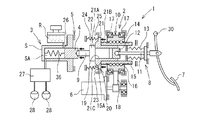
図1に示されるのは、自動車のブレーキ制御装置に組み込まれた電動アクチュエーション1の概略図である。電動アクチュエーション1は、本発明に係る電動倍力装置2とマスタシリンダ3とを含む。マスタシリンダ3は、内部をピストン4が摺動するシリンダ本体Sと、マスタシリンダ3から吐出されるブレーキ液を貯留するリザーバRとから概略構成されている。シリンダ本体Sの内部には、ピストン4により画成される圧力室SAが形成されている。シリンダ本体Sには、この圧力室SAとリザーバRとを連通するリザーバポート26が形成されている。そして、マスタシリンダ3で発生したブレーキ液圧は、液圧回路27に供給されてから車両の車輪毎に設けられた各ホイールシリンダ28へ供給される。液圧回路27は、各ホイールシリンダ28へのブレーキ液圧を制御して車両の挙動を制御するようになっている。なお、図1及び図2におけるマスタシリンダ3は、ピストン4が1個のシングル型のマスタシリンダで表しているが、2個のピストン4を軸方向に並べて配置したタンデム型のマスタシリンダを適用することができる。
A first embodiment of the present invention will be described with reference to the accompanying drawings.
FIG. 1 shows a schematic diagram of an electric actuation 1 incorporated in a brake control device of an automobile. The electric actuation 1 includes an
電動倍力装置2は、各図でその一部を図示するハウジング5と、該ハウジング5に取り付けられる電動モータ6と、ブレーキペダル7の操作により駆動される入力機構8と、一端部がマスタシリンダ3のピストン4に当接される出力ロッド9と、電動モータ6により駆動されて出力ロッド9を軸方向(図1における左右方向)へ進退させるピストン推進機構10とを含む。入力機構8は、入力ロッド11と、該入力ロッド11の一端部(マスタシリンダ3側の端部であって図1における左側の端部)が係合されるカップ12と、ハウジング5と入力ロッド11との間に設けられてブレーキペダル7へ反力を付与するストロークシミュレータ13とを含んで構成されている。
The
ピストン推進機構10は、ナット部材14と、ねじ軸部材15と、これら両者の間を転動可能な複数個のボール16とよりなり、ボールねじ機構を構成している。ナット部材14は、ハウジング5に設けられた一対の軸受17により回転可能に支持されてベルト18を介して電動モータ6により回転駆動される。ねじ軸部材15は、本実施形態においては、外周面に螺旋溝が形成された中空の筒状部材となっている。ねじ軸部材15の一端部(マスタシリンダ3側の端部であって図1における左側の端部)の内周側には、軸孔19を有する軸部材20が摺動可能に嵌合される。
The
軸部材20の軸孔19には、その一端側(マスタシリンダ3側であって図1における左側)に、出力ロッド9の他端部が摺動可能に嵌合され、他端側に、入力機構8のカップ12が摺動可能に嵌合されるようになっている。また、軸部材20の一端部には、ねじ軸部材15の外径よりも大きな外径寸法を有するフランジ21が形成されている。フランジ21は、図1に示されるように、軸部材20の一端側の径方向内方側端面21Aに、出力ロッド9の大径部22が当接され、また、軸部材20の他端側の端面21Bに軸部材20のフランジ21には、ねじ軸部材15の一端部側端面15Aが当接される。本実施形態においては、ねじ軸部材15と、フランジ21を有する軸部材20とから、電動モータ5の駆動によりマスタシリンダ3のピストン4を推進するピストン推進部材が構成されている。
In the
ハウジング5には、一端部(マスタシリンダ3側の端部であって図1における左側の端部)がハウジング5に固定されるとともに、他端部に環形状の座部23が取り付けられた戻しばね24を有している。戻しばね24は、軸部材20が所定量以上前進してピストン4を推進しているときに、軸部材20をその後退方向に付勢するように設けられている。この戻しばね24は、軸部材20によってピストン4を推進している最中に電動モータ6が失陥した場合に、軸部材20を後退させてマスタシリンダ3の圧力室SAで発生しているブレーキ液圧を解除して車両のブレーキロックを防止するようになっている。座部23は、その外周側がハウジング5に形成された受面25に対向し、その内周側がフランジ21における軸部材20の一端側の径方向外方側端面21Cに対向するように配置されている。図1に示されるブレーキペダル7の非操作時(以下、非制動時という)の状態では、戻しばね24は、座部23の外周側がハウジングの受面25により受け止められて圧縮側に撓んだ状態となっており、いわゆる、セット荷重を有している。ここで、戻しばね24の座部23と軸部材20のフランジ21の径方向外方側端面21Cとの軸方向距離(図1における左右方向への距離)をAとし、マスタシリンダ3におけるピストン4とリザーバポート26との軸方向距離、いわゆる、無効ストロークをBとした場合、非制動時の状態における距離AをA0、非制動時の状態における距離BをB0とすると、A0=B0、すなわち、距離A0と距離B0とが等しくなるように構成されている。このように構成することで、マスタシリンダの無効ストロークが終了するときに戻しばね24の座部23と軸部材20のフランジ21の径方向外方側端面21Cとが当接して、戻しばね24によって軸部材20に所定の抵抗が付与されるようになっている。
One end of the housing 5 (the end on the
これにより、図1に示される非制動時の状態から、電動モータ6の駆動によりナット部材14を一方向に回転させて、ねじ軸部材15、軸部材20、出力ロッド9及びマスタシリンダ3のピストン4を推進(図1における左方向へ移動)させると、図2に示されるように、距離Aが0になった時点、すなわち、軸部材20のフランジ21の径方向外方側端面21Cが戻しばね24の座部23の内周側に当接した時点で、距離Bが0になる。この軸部材20のフランジ21が戻しばね24の座部23に当接された時点では、ピストン推進機構10は、ピストン4がリザーバポート26を閉塞する直前の位置、すなわち、マスタシリンダ3が液圧を発生する位置(以下、液圧発生位置という)の直前の位置に到達される。
Accordingly, the
第1実施形態における抵抗付与機構は、非制動時の状態におけるピストン推進機構10の戻しばね24(座部23)とフランジ21との間に、前述した距離A0(A0=B0)を設けることにより成立する。そして、以上の説明から容易に理解できるように、抵抗付与機構は、図1に示される非制動時におけるピストン推進機構10の初期位置から、図2に示される液圧発生位置に到達する直前の位置まで移動した時に、軸部材20へ所定の抵抗を付与することが可能である。
The resistance applying mechanism according to the first embodiment is configured by providing the above-described distance A0 (A0 = B0) between the return spring 24 (seat portion 23) and the
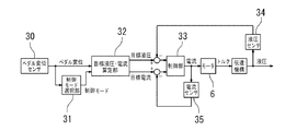
次に、ピストン推進機構10が受ける抵抗に応じて変化する電動モータ6の電流値に基づき電動モータ6をフィードバック制御する制御装置29の制御を、図4に示されるブロック図及び図5に示されるフローチャートに基づき説明する。
ブレーキペダル7が操作されると、ペダル変位センサ30によって、ブレーキペダル7の変位量が測定される(図5のステップS1)。次に、制御モード選択部31によって、ペダル変位センサ30の測定結果に基づき、ペダル変位量が無効ストローク領域であるか否か、すなわち、制動力を発生させるまでに至らないペダル変位量であるか否かが判定される(図5のステップS2)。
Next, the control of the control device 29 that feedback-controls the
When the brake pedal 7 is operated, the displacement amount of the brake pedal 7 is measured by the pedal displacement sensor 30 (step S1 in FIG. 5). Next, based on the measurement result of the
制御モード選択部31は、ペダル変位量が無効ストローク領域外であると判定した場合(図5のステップS2のNo)、液圧制御モードを選択する。液圧制御モードでは、目標液圧・電流算定部32によって、ブレーキペダル7の変位量に基づき、マスタシリンダ3で発生させる目標液圧が算定される(図5のステップS3)。そして、制御部33は、図5のステップS4において算定された目標液圧と、図5のステップS4において液圧センサ34によって測定されるマスタシリンダ3におけるブレーキ液圧とが等しくなるように、電動モータ6が制御される(図5のステップS5)。換言すると、電流センサ35によって測定される電動モータ6の電流値(ピストン推進機構10に付与される負荷)が目標液圧に対応する値となるように、電動モータ6が制御される。
When it is determined that the pedal displacement amount is outside the invalid stroke region (No in step S2 in FIG. 5), the control
他方、制御モード選択部31は、ペダル変位量が無効ストローク領域内であると判定した場合(図5のステップS2のYes)、電流制御モードを選択する。電流制御モードでは、電流センサ35によって検出された電動モータ6の電流値、換言すると、ピストン推進機構10に付与される抵抗に基づき、電動モータ6が制御される。より詳細に説明すると、目標液圧・電流算定部32は、マスタシリンダ3の戻しばね36による抵抗L1(図3参照)を越えて、且つ、軸部材20及びねじ軸部材15に付与される抵抗L2(図3参照)に満たないような抵抗L(L2>L>L1)、すなわち、マスタシリンダ3の戻しばね36による抵抗L1を越えて、且つ、マスタシリンダ3の戻しばね36による抵抗L1と軸部材20のフランジ21に当接された戻しばね24による抵抗L3(図3参照)との合計の負荷L2(L2=L1+L3)に満たないような抵抗L、に相当するトルクを電動モータ6が発生するような電流値を目標電流値に設定する(図5のステップS6)。次に、制御部33は、目標電流値を読み込み(図5のステップS7)、電流センサ35の測定値が目標電流値に等しくなるように、電動モータ6を制御する(図5のステップS8)。
On the other hand, when it is determined that the pedal displacement amount is within the invalid stroke region (Yes in step S2 in FIG. 5), the control
ここで、特許文献1に記載されているような従前の電動倍力装置では、マスタシリンダのピストンを推進するために、電動モータの回転位置をレゾルバで検出することで、回転位置に相当するピストンの移動位置を算出して、ブレーキペダルの操作量に対応するブレーキ液圧を発生する目標ピストン位置となるように、電動モータを位置制御している。また、上記従前の電動倍力装置には、マスタシリンダのブレーキ液圧を検出する液圧センサが設けられているので、上記のレゾルバを用いなくとも、液圧センサの検出値をフィードバック制御して、ブレーキペダルの操作量に対応するブレーキ液圧を発生するように、液圧制御を行うことも可能になっている。しかし、液圧制御を行う場合、マスタシリンダのピストンの無効ストローク領域では、液圧が発生しないので、液圧センサによるフィードバック制御が行えず、ブレーキペダルの操作に応じた液圧発生開始時期を精度よく制御することができなかった。このような観点からも無効ストローク領域ではレゾルバによる電動モータの位置制御が必要となっていた。 Here, in the conventional electric booster as described in Patent Document 1, in order to propel the piston of the master cylinder, the piston corresponding to the rotational position is detected by detecting the rotational position of the electric motor with a resolver. The position of the electric motor is calculated and the electric motor is position-controlled so that the target piston position for generating the brake hydraulic pressure corresponding to the operation amount of the brake pedal is obtained. Further, since the conventional electric booster is provided with a hydraulic pressure sensor for detecting the brake hydraulic pressure of the master cylinder, the detected value of the hydraulic pressure sensor is feedback controlled without using the resolver. The hydraulic pressure control can be performed so as to generate the brake hydraulic pressure corresponding to the operation amount of the brake pedal. However, when hydraulic pressure control is performed, no hydraulic pressure is generated in the invalid stroke area of the piston of the master cylinder, so feedback control by the hydraulic pressure sensor cannot be performed, and the hydraulic pressure generation start time according to the brake pedal operation is accurate. I couldn't control it well. From this point of view, it is necessary to control the position of the electric motor by the resolver in the invalid stroke region.
第1実施形態によれば、電動モータ6の駆動によって、ピストン推進機構10が、非制動時の初期位置(図1参照)から液圧発生位置の直前の位置(図2参照)まで移動した時点で、軸部材20のフランジ21が戻しばね24に当接することにより、軸部材20に所定の抵抗を付与させている。これにより、軸部材20に付与される所定の抵抗をねじ軸部材15、ナット部材14、及びベルト18を介して電動モータ6に伝達し、この所定の抵抗を電動モータ6の電流値によって検出することで、軸部材20の位置、延いては、マスタシリンダ3のピストン4が液圧発生位置に到達することを検出できる。これにより、軸部材20やねじ軸部材15、ひいてはピストン4の軸方向位置を検出するために従前の電動倍力装置に採用されていた電動モータ6の回転変位を検出するためのレゾルバが不要になる。したがって、レゾルバを使用しない場合には、電動倍力装置2の製造時における、煩雑な組付及び調整作業がなくなり、電動倍力装置2の製造効率を向上させることが可能である。なお、煩雑な組付及び調整作業が不要な回転位置検出装置であれば、この回転位置検出装置を電動倍力装置に設けて電動モータ6の回転変位を検出するようにしてもよい。
According to the first embodiment, when the
次に、本発明の第2実施形態を図6、7に基づいて説明する。
なお、第2実施形態の電動倍力装置42は、前述した第1実施形態の電動倍力装置2に対して、抵抗付与機構の構造のみが異なり、基本構造が同一である。したがって、以下の説明においては、第1実施形態と同一又は相当する構成には、同一の名称及び符号を付与するとともに、明細書の記載を簡潔にすることを目的に重複する説明を省略する。
Next, a second embodiment of the present invention will be described with reference to FIGS.
The
前述したように、第1実施形態では、電動モータ6の駆動によって、ピストン推進機構10が、非制動時の初期位置(図1参照)から液圧発生位置の直前の位置(図2参照)まで移動した時点で、軸部材20のフランジ21を戻しばね24に当接させて所定の抵抗を付与していた。これに対して、第2実施形態では、図6に示されるように、第1実施形態のハウジング5の受部25が設けられておらず、戻しばね24’の他端部が軸部材20’のフランジ21’に常時当接するようになっている。これにより、ピストン推進機構10が非制動時の初期位置(図6参照)に位置している状態で、戻しばね24によりピストン推進機構10へ負荷が付与されている。
As described above, in the first embodiment, the driving of the
そして、第2実施形態では、ハウジング5に弾性体によって構成された突起43が軸部材20’のフランジ21’に軸方向で対向するように設けられている。この突起43は、電動モータ6の駆動によって、軸部材20’のフランジ21’が、非制動時の初期位置(図6参照)から液圧発生位置の直前の位置(図7参照)まで移動した時点で、軸部材20’のフランジ21’に接触するようになっている。このように、第2実施形態では、フランジ21’が突起43に接触することで軸部材20に所定の抵抗を付与して、この抵抗を電動モータ6の電流値によって検出することにより、軸部材20’の位置、延いては、マスタシリンダ3のピストン4が液圧発生位置に到達することを検出できるように構成される。なお、突起43は、環形に形成された1つの部材で構成することができる。また、突起43は、例えば円錐形の複数個の突起43を同一円周状に配置してもよい。
In the second embodiment, a
第2実施形態によれば、電動モータ6の駆動によって、軸部材20’が、非制動時の初期位置(図6参照)から液圧発生位置の直前の位置(図7参照)まで移動した時点で、軸部材20のフランジ21が突起43に接触して軸部材20’に所定の抵抗を付与するので、この所定の抵抗を電動モータ6の電流値によって検出することで、軸部材20’の位置、延いては、マスタシリンダ3のピストン4が液圧発生位置に到達することを検出できる。これにより、マスタシリンダ3のピストン4が位置を検出するために従前の電動倍力装置で採用されていた電動モータ6の回転変位の検出のためのレゾルバ等の回転位置検出装置が不要になり、電動倍力装置42の製造時に、煩雑な組付及び調整作業がなくなり、電動倍力装置42の製造効率を向上させることが可能である。
According to the second embodiment, when the
2 電動倍力装置、3 マスタシリンダ、4 ピストン、5 ハウジング、6 電動モータ、7 ブレーキペダル、10 ピストン推進機構、11 入力ロッド、15 ねじ軸部材(ピストン推進部材)、20 軸部材(ピストン推進部材)、21 フランジ部(ピストン推進部材)、24 戻しばね(抵抗付与機構) 2 electric booster, 3 master cylinder, 4 piston, 5 housing, 6 electric motor, 7 brake pedal, 10 piston propulsion mechanism, 11 input rod, 15 screw shaft member (piston propulsion member), 20 shaft member (piston propulsion member) ), 21 Flange (piston propulsion member), 24 Return spring (resistance imparting mechanism)
Claims (3)
ハウジングに設けられて前記電動モータの駆動によりマスタシリンダのピストンを推進するピストン推進部材と、
前記ピストン推進部材に付与される抵抗に応じて変化する前記電動モータの電流値に基づき前記電動モータをフィードバック制御する制御装置と、
非制動時の初期位置から移動して前記マスタシリンダのピストンにより液圧を発生する液圧発生位置の直前の所定位置まで前記ピストン推進部材が移動した時点で前記ピストン推進部材に当接し、当該所定位置に移動する前よりも大きな所定の抵抗を付与する抵抗付与機構と、
を備えることを特徴とする電動倍力装置。 An electric motor controlled in accordance with the operation of an input rod connected to the brake pedal;
A piston propulsion member that is provided in the housing and propels the piston of the master cylinder by driving the electric motor;
A control device that feedback-controls the electric motor based on a current value of the electric motor that changes in accordance with a resistance applied to the piston propulsion member;
It said piston propulsion member when said piston propulsion member is moved is moved to a predetermined position immediately before the hydraulic pressure generating position for generating a hydraulic pressure by the piston of the master cylinder from an initial position of non-braking contact, the predetermined A resistance applying mechanism that applies a predetermined resistance larger than that before moving to a position ;
An electric booster comprising:
Priority Applications (1)
| Application Number | Priority Date | Filing Date | Title |
|---|---|---|---|
| JP2011216072A JP5875310B2 (en) | 2011-09-30 | 2011-09-30 | Electric booster |
Applications Claiming Priority (1)
| Application Number | Priority Date | Filing Date | Title |
|---|---|---|---|
| JP2011216072A JP5875310B2 (en) | 2011-09-30 | 2011-09-30 | Electric booster |
Publications (3)
| Publication Number | Publication Date |
|---|---|
| JP2013075595A JP2013075595A (en) | 2013-04-25 |
| JP2013075595A5 JP2013075595A5 (en) | 2014-11-06 |
| JP5875310B2 true JP5875310B2 (en) | 2016-03-02 |
Family
ID=48479410
Family Applications (1)
| Application Number | Title | Priority Date | Filing Date |
|---|---|---|---|
| JP2011216072A Active JP5875310B2 (en) | 2011-09-30 | 2011-09-30 | Electric booster |
Country Status (1)
| Country | Link |
|---|---|
| JP (1) | JP5875310B2 (en) |
Families Citing this family (3)
| Publication number | Priority date | Publication date | Assignee | Title |
|---|---|---|---|---|
| JP5815183B2 (en) * | 2013-10-04 | 2015-11-17 | 本田技研工業株式会社 | Brake device for vehicle |
| CN106627548B (en) * | 2016-11-30 | 2019-05-07 | 浙江三星机电股份有限公司 | Electric booster braking device based on variable rate spring |
| KR102620655B1 (en) * | 2017-01-18 | 2024-01-04 | 현대모비스 주식회사 | Brake apparatus |
Family Cites Families (3)
| Publication number | Priority date | Publication date | Assignee | Title |
|---|---|---|---|---|
| JP2007131130A (en) * | 2005-11-10 | 2007-05-31 | Hitachi Ltd | Brake device |
| JP5161828B2 (en) * | 2009-04-01 | 2013-03-13 | 日立オートモティブシステムズ株式会社 | Brake device for vehicle |
| DE102010001939B4 (en) * | 2010-02-15 | 2012-05-16 | Robert Bosch Gmbh | Brake booster and method and apparatus for its operation |
-
2011
- 2011-09-30 JP JP2011216072A patent/JP5875310B2/en active Active
Also Published As
| Publication number | Publication date |
|---|---|
| JP2013075595A (en) | 2013-04-25 |
Similar Documents
| Publication | Publication Date | Title |
|---|---|---|
| JP5483042B2 (en) | Brake control device | |
| JP5685791B2 (en) | Booster | |
| JP5721068B2 (en) | Electric booster | |
| JP6383959B2 (en) | Booster, stroke simulator and resistance applying device | |
| JP5756275B2 (en) | Electric booster | |
| WO2011033983A1 (en) | Parking brake control device | |
| CN111094089B (en) | Electric booster | |
| JP6771640B2 (en) | Electric booster | |
| WO2011099277A1 (en) | Electric servo device and brake device employing same | |
| JP5875310B2 (en) | Electric booster | |
| JPWO2019059201A1 (en) | Electric booster | |
| JP2013071536A (en) | Electric booster device | |
| JP6238647B2 (en) | Electric booster | |
| JP6205821B2 (en) | Electric parking brake control device | |
| JP2009227230A (en) | Electric booster | |
| JP5784328B2 (en) | Brake device | |
| JP4822003B2 (en) | Electric booster | |
| JP2011131886A (en) | Electric booster | |
| JP2009208523A (en) | Electric brake booster | |
| JPH11301461A (en) | Brake device | |
| JP2014008891A (en) | Braking device | |
| JP2013071722A (en) | Stroke simulator | |
| JP6379366B2 (en) | Electric booster | |
| JP2012136151A (en) | Brake device | |
| JP5262826B2 (en) | Brake booster |
Legal Events
| Date | Code | Title | Description |
|---|---|---|---|
| A521 | Request for written amendment filed |
Free format text: JAPANESE INTERMEDIATE CODE: A523 Effective date: 20140919 |
|
| A621 | Written request for application examination |
Free format text: JAPANESE INTERMEDIATE CODE: A621 Effective date: 20140919 |
|
| A977 | Report on retrieval |
Free format text: JAPANESE INTERMEDIATE CODE: A971007 Effective date: 20150416 |
|
| A131 | Notification of reasons for refusal |
Free format text: JAPANESE INTERMEDIATE CODE: A131 Effective date: 20150527 |
|
| A521 | Request for written amendment filed |
Free format text: JAPANESE INTERMEDIATE CODE: A523 Effective date: 20150727 |
|
| TRDD | Decision of grant or rejection written | ||
| A01 | Written decision to grant a patent or to grant a registration (utility model) |
Free format text: JAPANESE INTERMEDIATE CODE: A01 Effective date: 20151224 |
|
| A61 | First payment of annual fees (during grant procedure) |
Free format text: JAPANESE INTERMEDIATE CODE: A61 Effective date: 20160119 |
|
| R150 | Certificate of patent or registration of utility model |
Ref document number: 5875310 Country of ref document: JP Free format text: JAPANESE INTERMEDIATE CODE: R150 |
|
| R250 | Receipt of annual fees |
Free format text: JAPANESE INTERMEDIATE CODE: R250 |
|
| S533 | Written request for registration of change of name |
Free format text: JAPANESE INTERMEDIATE CODE: R313533 |
|
| R350 | Written notification of registration of transfer |
Free format text: JAPANESE INTERMEDIATE CODE: R350 |
|
| R250 | Receipt of annual fees |
Free format text: JAPANESE INTERMEDIATE CODE: R250 |
|
| R250 | Receipt of annual fees |
Free format text: JAPANESE INTERMEDIATE CODE: R250 |
|
| R250 | Receipt of annual fees |
Free format text: JAPANESE INTERMEDIATE CODE: R250 |