JP2009201822A - Game machine - Google Patents

Game machine Download PDF

Info

Publication number
JP2009201822A
JP2009201822A JP2008048574A JP2008048574A JP2009201822A JP 2009201822 A JP2009201822 A JP 2009201822A JP 2008048574 A JP2008048574 A JP 2008048574A JP 2008048574 A JP2008048574 A JP 2008048574A JP 2009201822 A JP2009201822 A JP 2009201822A
Authority
JP
Japan
Prior art keywords
combination
symbol display
determined
reel
symbol
Prior art date
Legal status (The legal status is an assumption and is not a legal conclusion. Google has not performed a legal analysis and makes no representation as to the accuracy of the status listed.)
Pending
Application number
JP2008048574A
Other languages
Japanese (ja)
Inventor
Eiji Miyamoto
英司 宮本
Tadataka Kuroda
恭敬 黒田
Current Assignee (The listed assignees may be inaccurate. Google has not performed a legal analysis and makes no representation or warranty as to the accuracy of the list.)
Universal Entertainment Corp
Original Assignee
Aruze Corp
Priority date (The priority date is an assumption and is not a legal conclusion. Google has not performed a legal analysis and makes no representation as to the accuracy of the date listed.)
Filing date
Publication date
Application filed by Aruze Corp filed Critical Aruze Corp
Priority to JP2008048574A priority Critical patent/JP2009201822A/en
Publication of JP2009201822A publication Critical patent/JP2009201822A/en
Pending legal-status Critical Current

Links

Images

Abstract

<P>PROBLEM TO BE SOLVED: To provide a game machine improving amusement in a game for a game player by providing working of an Assist Time with variation. <P>SOLUTION: The game machine determines whether the communication state (Assist Time) for communicating prize-winning bonus assisting information to the player is worked or not and a period of the state. When the working of the state is determined, the game machine determines whether a specified pattern display state being displayed in a pattern display region for displaying a pattern display state consisting of a combination of a plurality of patterns is allowed or not and that either specified pattern state out of a plurality of the pattern states is displayed in the region. The game machine works the communication state from the specified pattern display state being displayed in the region and communicates the working of the communication state to the player. According to a determined period of the communication state, the specified pattern display state to be displayed in the region is determined. <P>COPYRIGHT: (C)2009,JPO&INPIT

Description

本発明は、遊技機に関する。   The present invention relates to a gaming machine.

従来、複数の図柄が周面に描かれた複数のリールと、これら各リールに対応して複数設けられるとともに各リールの周面に描かれた一部の図柄を表示する図柄表示窓とを備え、遊技者によるメダル等の遊技価値の投入とスタートレバーに対する開始操作とに基づいて全リールを回転させ、遊技者によるストップボタンに対する停止操作に基づいて各リールを停止させることにより図柄表示窓に図柄を停止表示する遊技機(いわゆる「パチスロ」)が知られている。こうした遊技機は、図柄表示窓に、役に係る図柄の組合せが停止表示された場合、すなわち、役が成立した場合に、遊技者に対して特典(例えば、メダル)を付与する。   Conventionally, it has a plurality of reels on which a plurality of symbols are drawn on the peripheral surface, and a symbol display window that is provided in correspondence with each reel and displays a part of the symbols drawn on the peripheral surface of each reel. The symbols are displayed on the symbol display window by rotating all the reels based on the player's input of game value such as medals and the start operation on the start lever, and stopping each reel based on the stop operation on the stop button by the player. A game machine (so-called “pachi-slot”) that stops and displays is known. Such a gaming machine gives a bonus (for example, a medal) to a player when a combination of symbols related to a combination is stopped and displayed on the symbol display window, that is, when a combination is established.

現在主流の遊技機は、遊技者の開始操作に基づいて予め遊技機内部において複数の役の中から1又は2以上の役を抽籤して(以下、「内部抽籤」という)、当籤した役(以下、「内部当籤役」という)と遊技者の停止操作とに基づいてリールの停止制御を行い、内部当籤役に係る図柄の組合せを図柄表示窓に停止表示させる。このとき、内部抽籤において何れの役も当籤しなかった場合(すなわち、内部抽籤の結果がハズレの場合)には、何れのタイミングで停止操作が行われたとしても役に係る図柄の組合せが表示されない。また、内部当籤役として決定された役によっては、適切なタイミングで停止操作が行われなければ成立しない役や、何れのタイミングで停止操作が行われても成立する役がある。すなわち、適切なタイミングで停止操作が行われなければ成立しない役が内部当籤役として決定された場合には、適切なタイミングでの停止操作(いわゆる「目押し」)が必要となることから、遊技者には停止操作に関する一定の技量が要求される。   A mainstream gaming machine draws one or two or more roles from among a plurality of roles in advance in the gaming machine based on the start operation of the player (hereinafter referred to as “internal lottery”), Hereinafter, the reel stop control is performed based on the “internal winning combination” and the player's stop operation, and the symbol combination related to the internal winning combination is stopped and displayed on the symbol display window. At this time, if any combination is not won in the internal lottery (that is, the result of the internal lottery is lost), the combination of symbols related to the combination is displayed regardless of the timing of the stop operation. Not. Further, depending on the combination determined as the internal winning combination, there are a combination that cannot be established unless the stop operation is performed at an appropriate timing, and a combination that is established regardless of the stop operation performed at any timing. In other words, if a winning combination that is not achieved if a stop operation is not performed at an appropriate timing is determined as an internal winning combination, a stop operation at a proper timing (so-called “promotion”) is required. The person is required to have a certain skill regarding the stop operation.

また、一部の遊技機においては、内部当籤役として決定された役であっても、適切なタイミングで停止操作を行わなければ成立しない役や、予め定められた順序でリールに対する停止操作が行われなければ成立しない役などがある。このように、内部当籤役に決定された役を成立させられない事態、いわゆる取りこぼしが起きないように遊技者に対して内部当籤役として決定された役を成立させるための情報を報知する状態(「アシストタイム(AT)」という)を作動させるか否かをAT抽籤により決定する遊技機が知られている(例えば、特許文献1)。
特開2004−201705号公報
Also, in some gaming machines, even if the winning combination is determined as an internal winning combination, if the stopping operation is not performed at an appropriate timing, the winning combination is not performed, or the reels are stopped in a predetermined order. There is a role that is not established if it is not done. In this way, a situation in which information for establishing the combination determined as the internal winning combination is notified to the player so that the situation in which the determined combination as the internal winning combination cannot be established, that is, so-called spillover does not occur ( There is known a gaming machine that determines whether or not to operate an “assist time (AT)” by an AT lottery (for example, Patent Document 1).
JP 2004-201705 A

しかしながら、上述の遊技機によれば、単にAT抽籤に当籤することでATが作動することから、ATの作動に関して面白みが無く、長期にわたって遊技を行う遊技者の興趣を低下させるおそれがあった。   However, according to the above-described gaming machine, since the AT is operated simply by winning the AT lottery, there is no interest in the operation of the AT, and there is a possibility that the interest of the player who plays the game for a long time may be reduced.

本発明は、上記課題に鑑みてなされたものであり、ATの作動に関して変化を加えることによって遊技者の遊技に対する興趣を向上させる遊技機を提供することを目的とする。   The present invention has been made in view of the above problems, and an object of the present invention is to provide a gaming machine that improves the interest of a player in playing a game by changing the operation of an AT.

上記の課題を解決するために、請求項1に記載の発明に係る遊技機は、複数の図柄が描かれた複数のリール(例えば、後述のメインリール2〜4、サブリール5〜7)と、前記リールの周面に配された複数の図柄の一部を表示する図柄表示領域(後述の図柄表示領域39、サブリール図柄表示領域5A〜7A)とを有する図柄表示手段と、所定の開始条件(例えば、メダルの投入を検出した後に、開始操作を検出すること)が成立したことに基づいて、前記リールを回転させることにより、前記図柄表示領域に表示されている図柄を変動させる図柄変動手段(例えば、後述のステッピングモータ45L、45C、45R、ステッピングモータ101)と、前記所定の開始条件が成立したことに基づいて、所定の確率で内部当籤役を決定する当籤役決定手段(例えば、後述のメインCPU64)と、停止操作を検出する停止操作検出手段(例えば、後述のストップスイッチ78LS、78CS、78RS)と、前記当籤役決定手段により決定された内部当籤役と前記停止操作検出手段により検出される停止操作とに基づいて、前記リールの回転を停止させることにより、前記図柄表示領域に表示されている図柄の変動を停止させる停止制御手段(例えば、後述のメインCPU64、サブCPU82)と、前記当籤役決定手段によって所定の役(例えば、後述の3択役群L、3択役群C、3択役群R)が内部当籤役として決定された場合に、当該所定の役に係る図柄の組合せを前記図柄表示領域に表示させるための当籤役補助情報を遊技者に報知する報知状態(例えば、後述のAT遊技状態)を作動させるか否かと、当該報知状態の期間(例えば、後述のATセット数カウンタにセットする値)とを、所定の確率で決定する報知状態決定手段(例えば、後述のサブCPU82)と、前記報知状態決定手段により報知状態を作動させることが決定された場合に、複数の図柄の組合せからなる特定図柄表示態様(例えば、後述の「緑7図柄−緑7図柄−緑7図柄」、「赤7図柄−赤7図柄−赤7図柄」)を前記図柄表示領域に表示させることを許可するか否かと、複数ある当該特定図柄表示態様の中から何れの特定図柄表示態様を当該図柄表示領域に表示させるかとを、所定の確率で決定する特定図柄決定手段(例えば、後述のサブCPU82)と、前記特定図柄決定手段により前記図柄表示領域に特定図柄表示態様を表示させることが許可された場合であって、前記停止操作検出手段により所定のタイミングで停止操作が検出されたときに、当該特定図柄決定手段により決定された特定図柄表示態様を当該図柄表示領域に表示させる特定図柄表示制御手段(例えば、後述のサブCPU82)と、前記特定図柄表示制御手段により前記図柄表示領域に特定図柄表示態様が表示されたことに基づいて、前記報知状態決定手段により決定された報知状態の期間、当該報知状態を作動させる報知状態制御手段(例えば、後述のサブCPU82)と、前記特定図柄表示制御手段により前記図柄表示領域に特定図柄表示態様が表示されたことに基づいて、前記報知状態制御手段により報知状態が作動させられていることを報知する報知状態報知手段(例えば、後述のサブCPU82、4thリール8、リールバックランプ48a〜48c、スピーカ54、96L、96R)と、前記報知状態制御手段により報知状態が作動させられている際に、前記当籤役決定手段によって前記所定の役が内部当籤役として決定された場合に、前記当籤役補助情報を報知する当籤役情報報知手段(例えば、後述のサブCPU82)と、を備え、前記特定図柄決定手段は、前記報知状態決定手段により決定された報知状態の期間に応じて、前記図柄表示領域に表示させる前記特定図柄表示態様を決定することを特徴とする。   In order to solve the above-described problem, a gaming machine according to the invention described in claim 1 includes a plurality of reels (for example, main reels 2 to 4 and sub reels 5 to 7 described later) on which a plurality of symbols are drawn, Symbol display means having a symbol display area (a symbol display area 39, sub-reel symbol display areas 5A to 7A described later) for displaying a part of a plurality of symbols arranged on the peripheral surface of the reel, and a predetermined start condition ( For example, a symbol changing means for changing a symbol displayed in the symbol display area by rotating the reel based on the fact that a start operation is detected after detecting the insertion of a medal) For example, a stepping motor 45L, 45C, 45R, which will be described later, and the stepping motor 101) and the predetermined winning condition are determined based on the establishment of the predetermined starting condition. A combination determining means (for example, a main CPU 64 described later), a stop operation detecting means for detecting a stop operation (for example, stop switches 78LS, 78CS, 78RS described later), and an internal winning combination determined by the winning combination determining means Based on the stop operation detected by the stop operation detecting means, stop control means (for example, a main control which will be described later) stops the change of the symbols displayed in the symbol display area by stopping the rotation of the reel. CPU64, sub-CPU 82) and the winning combination determining means determine a predetermined combination (e.g., 3 alternative combination group L, 3 alternative combination group C, 3 alternative combination group R described later) as an internal winning combination, A notification state (for example, an AT game to be described later) for notifying a player of winning combination assistance information for displaying a combination of symbols related to the predetermined combination in the symbol display area A notification state determining means (for example, a sub CPU 82 described later) for determining a period of the notification state (for example, a value set in an AT set number counter described later) with a predetermined probability. When it is determined that the notification state is activated by the notification state determination means, a specific symbol display mode consisting of a combination of a plurality of symbols (for example, “green 7 symbol-green 7 symbol-green 7 symbol” described later, "Red 7 symbol-Red 7 symbol-Red 7 symbol") is permitted to be displayed in the symbol display area, and any one of the specific symbol display modes is displayed in the symbol display mode. Specific symbol determining means (for example, a sub-CPU 82 described later) that determines whether to display in the area with a predetermined probability, and the specific symbol display mode is displayed in the symbol display area by the specific symbol determining means. When the stop operation is detected at a predetermined timing by the stop operation detecting means, the specific symbol display mode determined by the specific symbol determining means is displayed in the symbol display area. The notification determined by the notification state determination means based on the specific symbol display control means (for example, a sub CPU 82 described later) and the specific symbol display control means displaying the specific symbol display mode in the symbol display area. Based on the notification state control means (for example, a sub-CPU 82 described later) that activates the notification state during the state period and the specific symbol display mode displayed in the symbol display area by the specific symbol display control means, Notification state notification means (for example, a sub CPU 82 described later) that notifies that the notification state is activated by the notification state control means. (th reel 8, reel back lamps 48a to 48c, speakers 54, 96L, 96R) and the notification state control means, when the notification state is activated, the predetermined combination is determined by the winning combination determination means. A winning combination information notifying means (for example, a sub CPU 82 described later) for notifying the winning combination auxiliary information when determined as a winning combination, and the specific symbol determining means is determined by the notifying state determining means The specific symbol display mode to be displayed in the symbol display area is determined according to the period of the notification state.

この構成により、報知状態決定手段が、当籤役決定手段によって所定の役が内部当籤役として決定された場合に、当該所定の役に係る図柄の組合せを図柄表示領域に表示させるための当籤役補助情報を遊技者に報知する報知状態を作動させるか否かと、当該報知状態の期間とを、所定の確率で決定し、特定図柄決定手段は、報知状態決定手段により報知状態を作動させることが決定された場合に、複数の図柄の組合せからなる特定図柄表示態様を図柄表示領域に表示させることを許可するか否かと、複数ある当該特定図柄表示態様の中から何れの特定図柄表示態様を当該図柄表示領域に表示させるかとを、所定の確率で決定し、特定図柄表示制御手段は、特定図柄決定手段により図柄表示領域に特定図柄表示態様を表示させることが許可された場合であって、停止操作検出手段により所定のタイミングで停止操作が検出されたときに、当該特定図柄決定手段により決定された特定図柄表示態様を当該図柄表示領域に表示させ、報知状態制御手段は、特定図柄表示制御手段により図柄表示領域に特定図柄表示態様が表示されたことに基づいて、報知状態決定手段により決定された報知状態の期間、当該報知状態を作動させ、報知状態報知手段は、特定図柄表示制御手段により図柄表示領域に特定図柄表示態様が表示されたことに基づいて、報知状態制御手段により報知状態が作動させられていることを報知し、当籤役情報報知手段は、報知状態制御手段により報知状態が作動させられている際に、当籤役決定手段によって所定の役が内部当籤役として決定された場合に、当籤役補助情報を報知する。また、特定図柄決定手段は、報知状態決定手段により決定された報知状態の期間に応じて、図柄表示領域に表示させる特定図柄表示態様を決定する。   With this configuration, when the notification state determining unit determines that the predetermined combination is an internal winning combination by the winning combination determining unit, the winning combination assistance for displaying the combination of symbols related to the predetermined combination in the symbol display area. Whether or not to activate a notification state for notifying the player of information and a period of the notification state is determined with a predetermined probability, and the specific symbol determination unit is determined to activate the notification state by the notification state determination unit If it is, whether or not to allow a specific symbol display mode consisting of a combination of a plurality of symbols to be displayed in the symbol display area, and any specific symbol display mode from among the plurality of specific symbol display modes Whether to display in the display area is determined with a predetermined probability, and the specific symbol display control means is permitted to display the specific symbol display mode in the symbol display area by the specific symbol determining means. When the stop operation is detected at a predetermined timing by the stop operation detection means, the specific symbol display mode determined by the specific symbol determination means is displayed in the symbol display area, and the notification state control means Based on the fact that the specific symbol display mode is displayed in the symbol display area by the specific symbol display control means, the notification state is activated during the notification state determined by the notification state determination means. Based on the fact that the specific symbol display mode is displayed in the symbol display area by the specific symbol display control means, the notification state control means notifies that the notification state is activated, and the winning combination information notification means When the notification means is activated by the control means and the predetermined winning combination is determined as the internal winning combination by the winning combination determining means, To notify. Further, the specific symbol determining means determines the specific symbol display mode to be displayed in the symbol display area according to the period of the notification state determined by the notification state determining means.

したがって、当該遊技機によれば、報知状態を作動させることを決定した場合であっても、図柄表示領域に特定図柄表示態様が表示されなければ、報知状態の作動中であることを報知しないことから、遊技者は、報知状態を作動させることが決定されなかった場合であっても、報知状態を作動させることが決定されたのではないかと、図柄表示領域に特定図柄表示態様が表示されることを期待しつつ遊技を行うこととなる。すなわち、報知状態の作動に関して変化を加えることによって遊技者の遊技に対する興趣を向上させることができる。また、遊技者は、図柄表示領域に表示された特定図柄表示態様から報知状態が継続する期間を推測することができることから、図柄表示領域に表示される特定図柄表示態様に強い興味を抱き、遊技に対する興趣を向上させる。   Therefore, according to the gaming machine, even if it is determined to activate the notification state, if the specific symbol display mode is not displayed in the symbol display area, the notification state is not informed. Therefore, even if the player is not determined to activate the notification state, the specific symbol display mode is displayed in the symbol display area, indicating that it is determined to activate the notification state. Playing games while expecting that. That is, it is possible to improve the interest of the player in the game by adding a change regarding the operation of the notification state. In addition, since the player can infer the period during which the notification state continues from the specific symbol display mode displayed in the symbol display area, the player has a strong interest in the specific symbol display mode displayed in the symbol display area, and the game Improve interest in

また、請求項2に記載の発明に係る遊技機は、請求項1に記載の遊技機において、前記報知状態制御手段が、所定の中断条件(例えば、ATセット数カウンタの値が「2」以上である場合に、AT報知回数カウンタの値が「0」になるという条件)が充足されたことに基づいて、前記報知状態の作動を中断させ、前記特定図柄表示制御手段により再度、前記特定図柄表示態様が表示されたことに基づいて、当該報知状態の作動を再開させ、前記特定図柄決定手段は、前記報知状態制御手段により報知状態が中断させられている場合に、前記特定図柄表示態様を前記図柄表示領域に表示させることを許可するか否かと、複数ある当該特定図柄表示態様の中から何れの特定図柄表示態様を当該図柄表示領域に表示させるかとを、所定の確率で決定し、前記報知状態報知手段は、前記報知状態制御手段により報知状態の作動が中断させられている場合には、報知状態制御手段により報知状態が作動させられていることの報知を中断し、前記特定図柄表示制御手段により再度、前記特定図柄表示態様が表示されたことに基づいて、当該報知状態が作動させられていることの報知を再開することを特徴とする。   In addition, in the gaming machine according to the second aspect of the present invention, in the gaming machine according to the first aspect, the notification state control means has a predetermined interruption condition (for example, the value of the AT set number counter is "2" or more The condition of the AT notification count counter is “0”), the operation of the notification state is interrupted, and the specific symbol display control means again causes the specific symbol to be Based on the display mode being displayed, the operation of the notification state is resumed, and the specific symbol determination unit is configured to change the specific symbol display mode when the notification state is interrupted by the notification state control unit. Decide whether to allow display in the symbol display area and which specific symbol display mode to be displayed in the symbol display region from a plurality of the specific symbol display modes with a predetermined probability The notification state notification means interrupts notification that the notification state is operated by the notification state control means when the notification state operation is interrupted by the notification state control means, and Based on the fact that the specific symbol display mode is displayed again by the symbol display control means, the notification that the notification state is activated is resumed.

したがって、当該遊技機によれば、遊技者は、報知状態が作動中であることの報知が終了した場合であっても、再度、図柄表示領域に特定図柄表示態様が表示され、報知状態の作動が再開されるかもしれないという期待感を持って遊技を行うことができ、遊技に対する興趣を維持させることができる。   Therefore, according to the gaming machine, even when the notification that the notification state is in operation is finished, the player again displays the specific symbol display mode in the symbol display area and operates the notification state. The game can be played with the expectation that it may be resumed, and the interest in the game can be maintained.

また、請求項3に記載の発明に係る遊技機は、請求項1又は請求項2に記載の遊技機において、前記特定図柄決定手段が、前記当籤役決定手段により決定された内部当籤役に基づいて、前記図柄表示領域に特定図柄表示態様を表示させることを許可するか否かを決定することを特徴とする。   The gaming machine according to claim 3 is the gaming machine according to claim 1 or 2, wherein the specific symbol determining means is based on the internal winning combination determined by the winning combination determining means. Then, it is determined whether or not to allow the specific symbol display mode to be displayed in the symbol display area.

したがって、当該遊技機によれば、遊技者は、何れの役が内部当籤役として決定されるかについても期待感を持つこととなり、遊技に対する興趣を向上させる。   Therefore, according to the gaming machine, the player has a sense of expectation as to which role is determined as the internal winning combination, and the interest in the game is improved.

したがって、当該遊技機によれば、報知状態を作動させることを決定した場合であっても、図柄表示領域に特定図柄表示態様が表示されなければ、報知状態の作動中であることを報知しないことから、遊技者は、報知状態を作動させることが決定されなかった場合であっても、報知状態を作動させることが決定されたのではないかと、図柄表示領域に特定図柄表示態様が表示されることを期待しつつ遊技を行うこととなる。すなわち、報知状態の作動に関して変化を加えることによって遊技者の遊技に対する興趣を向上させることができる。また、遊技者は、図柄表示領域に表示された特定図柄表示態様から報知状態が継続する期間を推測することができることから、図柄表示領域に表示される特定図柄表示態様に強い興味を抱き、遊技に対する興趣を向上させる。   Therefore, according to the gaming machine, even if it is determined to activate the notification state, if the specific symbol display mode is not displayed in the symbol display area, the notification state is not informed. Therefore, even if the player is not determined to activate the notification state, the specific symbol display mode is displayed in the symbol display area, indicating that it is determined to activate the notification state. Playing games while expecting that. That is, it is possible to improve the interest of the player in the game by adding a change regarding the operation of the notification state. In addition, since the player can infer the period during which the notification state continues from the specific symbol display mode displayed in the symbol display area, the player has a strong interest in the specific symbol display mode displayed in the symbol display area, and the game Improve interest in

以下に、本発明の遊技機について、図面を用いて具体的に説明する。なお、以下の実施形態では、本発明の遊技機として、図柄を変動表示する3つの回転リールを備えた遊技機であって、コイン、メダルまたはトークンなどの他に、遊技者に付与されたカード等の遊技価値を用いて遊技することが可能な遊技機、いわゆるパチスロ遊技機を用いて説明する。また、以下の実施形態では、パチスロ遊技機を例に挙げて説明するが、本願発明の遊技機を限定するものではなく、パチンコ機やスロットマシンであってもよい。   The gaming machine of the present invention will be specifically described below with reference to the drawings. In the following embodiment, as a gaming machine of the present invention, a gaming machine having three rotating reels that variably display symbols, in addition to coins, medals, tokens, etc., a card given to a player A description will be given using a game machine capable of playing using a game value such as a so-called pachislot machine. Further, in the following embodiments, a pachislot gaming machine will be described as an example, but the gaming machine of the present invention is not limited, and a pachinko machine or a slot machine may be used.

まず、図1を参照して、本実施形態に係る遊技機の概観について説明する。なお、図1は、本実施形態に係る遊技機1の正面図である。   First, an overview of the gaming machine according to the present embodiment will be described with reference to FIG. FIG. 1 is a front view of the gaming machine 1 according to the present embodiment.

遊技機1は、前面に開閉可能に取り付けられた前面扉を備えたキャビネット構造をしており、キャビネット内部には小型のメインリール2、3、4や大型のサブリール5、6、7及び後述の主制御回路61(図8参照)などを収容している。   The gaming machine 1 has a cabinet structure with a front door attached to the front face so as to be openable and closable. Inside the cabinet, there are small main reels 2, 3, 4 and large sub-reels 5, 6, 7 and the following. A main control circuit 61 (see FIG. 8) and the like are accommodated.

キャビネット内部の中央部には、メインリール2、3、4が縦回転自在に横一列に設けられている。各メインリール2〜4の外周面には、複数種類の図柄によって構成される図柄列が配されている。また、メインリール2〜4の上方のキャビネット内部には、メインリール2〜4よりも大きなサブリール5、6、7が縦回転自在に横一列に設けられている。各サブリール5〜7の外周面には、複数種類の演出用の図柄によって構成される図柄列が配されている。さらに、サブリール5〜7の上方のキャビネット内部には、一つの4thリール8が回転自在に設けられている。4thリール8の外周面には、メインリール2〜4及びサブリール5〜7の外周面に描かれた図柄とは異なる、複数種類の演出用の図柄(例えば、RTチャレンジ、7RUSH、ボーナス確定、ハズレを示す図柄)によって構成される図柄列が配されている。なお、本実施形態のメインリール2〜4、サブリール5〜7は、本発明のリールを構成する。   Main reels 2, 3, and 4 are provided in a horizontal row at the center of the cabinet so as to be vertically rotatable. On the outer peripheral surface of each of the main reels 2 to 4, a symbol row composed of a plurality of types of symbols is arranged. Further, sub-reels 5, 6, and 7 larger than the main reels 2 to 4 are provided in a horizontal row so as to be vertically rotatable in the cabinet above the main reels 2 to 4. On the outer peripheral surface of each of the sub reels 5 to 7, a symbol row composed of a plurality of types of effect symbols is arranged. Further, one 4th reel 8 is rotatably provided inside the cabinet above the sub reels 5 to 7. On the outer peripheral surface of the 4th reel 8, there are a plurality of types of symbols for presentation (for example, RT challenge, 7RUSH, bonus confirmation, lost) which are different from the symbols drawn on the outer peripheral surfaces of the main reels 2 to 4 and the sub reels 5 to 7. The symbol sequence comprised by the symbol which shows) is arranged. The main reels 2 to 4 and the sub reels 5 to 7 of the present embodiment constitute the reels of the present invention.

前面扉には、キャビネット外部から各メインリール2〜4に配された図柄を視認可能とするための図柄表示領域39が設けられている。遊技者は、図柄表示領域39を通して各メインリール2〜4に配された図柄のうち夫々3つの図柄を視認することができる。また、前面扉には、各サブリール5〜7に配された図柄を視認可能とするためのサブリール図柄表示領域5A、6A、7Aと、4thリール8に配された図柄を視認可能とするための図柄表示領域51が設けられている。遊技者は、サブリール図柄表示領域5A〜7Aを通して各サブリール5〜7に配された図柄のうち夫々3つの図柄を視認することができ、図柄表示領域51を通して4thリール8に配された図柄のうち1つの図柄を視認することができる。また、サブリール図柄表示領域5A、6A、7Aの内側にはスモーク処理が施されており、リールバックランプ48a、48b、48c(図9参照)が照射された場合に各サブリール5〜7に配された図柄が視認可能となり、リールバックランプ48a、48b、48cが照射されないときには図柄の視認ができないような構成とされている。なお、本実施形態の図柄表示領域39、サブリール図柄表示領域5A、6A、7Aは、本発明の図柄表示領域を構成する。   The front door is provided with a symbol display area 39 for visually recognizing symbols arranged on the main reels 2 to 4 from the outside of the cabinet. The player can visually recognize three symbols out of symbols arranged on the main reels 2 to 4 through the symbol display area 39. Further, on the front door, the sub reel design display areas 5A, 6A, and 7A for making the symbols arranged on the sub reels 5 to 7 visible and the symbols arranged on the 4th reel 8 are made visible. A symbol display area 51 is provided. The player can visually recognize three symbols out of the symbols arranged on each of the sub reels 5 to 7 through the sub reel symbol display areas 5A to 7A, and among the symbols arranged on the 4th reel 8 through the symbol display area 51. One symbol can be visually recognized. In addition, smoke processing is applied to the inside of the sub-reel symbol display areas 5A, 6A, and 7A. When the reel back lamps 48a, 48b, and 48c (see FIG. 9) are irradiated, they are arranged on the sub-reels 5 to 7, respectively. The symbols can be visually recognized, and when the reel back lamps 48a, 48b, 48c are not irradiated, the symbols cannot be visually recognized. The symbol display area 39 and the sub-reel symbol display areas 5A, 6A, and 7A of the present embodiment constitute the symbol display area of the present invention.

メインリール2〜4、サブリール5〜7、4thリール8は、それぞれリールドラムの外周に複数種類の図柄が描かれたリールシートを装着した構造となっている。メインリール2〜4、サブリール5〜7、4thリール8を構成する各リールドラムの内部には、リールシートに描かれた図柄を背面から照射するためのLEDからなるリールバックランプ47a、47b、47c、リールバックランプ48a、48b、48c、リールバックランプ49(図9参照)がそれぞれ設けられている。   Each of the main reels 2 to 4, the sub reels 5 to 7, and the 4th reel 8 has a structure in which a reel sheet on which a plurality of types of symbols are drawn is mounted on the outer periphery of the reel drum. Inside each reel drum constituting the main reels 2 to 4 and the sub reels 5 to 7 and the 4th reel 8, reel back lamps 47a, 47b and 47c comprising LEDs for irradiating the pattern drawn on the reel sheet from the back side. Reel back lamps 48a, 48b and 48c, and a reel back lamp 49 (see FIG. 9) are provided.

メインリール2〜4の左右には略水平面の台座部がそれぞれ形成されている。右側の台座部にはメダル投入口9が設けられており、メダル投入口9に投入されたメダルに応じて、後述の入賞ラインが有効化されて有効ラインとなる。一方、左側の台座部には、遊技者による押しボタン操作(押圧操作)により、クレジットされているメダルを賭けるための1貯留メダル投入ボタン(1−BETボタン)30、2貯留メダル投入ボタン(2−BETボタン)31、及び3貯留メダル投入ボタン(最大BETボタン)32が設けられる。1貯留メダル投入ボタン30が押圧操作されることにより、クレジットされているメダルのうちの1枚が投入される。2貯留メダル投入ボタン31が押圧操作されることにより、クレジットされているメダルのうちの2枚が投入される。3貯留メダル投入ボタン32が押圧操作されることにより、クレジットされているメダルのうちの3枚{即ち、1ゲームにおいて投入することが可能な最大の投入枚数(以下、「最大投入枚数」という)}が投入される。これらの貯留メダル投入ボタン30〜32が押圧操作されることによって、後述の入賞ラインが有効化されて有効ラインとなる。   On the left and right sides of the main reels 2 to 4, pedestal portions having substantially horizontal surfaces are respectively formed. A medal insertion slot 9 is provided on the right pedestal portion, and a winning line, which will be described later, is activated according to the medal inserted into the medal insertion slot 9 to become an effective line. On the other hand, on the left pedestal portion, a 1-stored medal insertion button (1-BET button) 30 for betting credited medals by a player's push button operation (press operation), 2 a stored medal insertion button (2 -BET button) 31 and 3 stored medal insertion button (maximum BET button) 32 are provided. When one stored medal insertion button 30 is pressed, one of the credited medals is inserted. When the 2 stored medal insertion button 31 is pressed, two of the credited medals are inserted. When the three-stored medal insertion button 32 is pressed, three of the credited medals (that is, the maximum number that can be inserted in one game (hereinafter referred to as “maximum insertion number”)). } Is inserted. When these stored medal insertion buttons 30 to 32 are pressed, a later-described winning line is activated and becomes an activated line.

台座部前面の右寄りには、遊技者が遊技で獲得したメダルのクレジット(Credit)/払い出し(Pay)の切り替えを行うための貯留メダル精算ボタン37が設けられている。貯留メダル精算ボタン37に対する遊技者の操作によって払出モード又はクレジットモードの切り替えが行われる。クレジットモードでは、入賞が成立すると、入賞に対応する払出枚数分のメダルがクレジットされる。また、払出モードでは、入賞が成立すると、入賞に対応する払出枚数分のメダルが正面下部のメダル払出口53から払い出され、このメダル払出口53から払い出されたメダルはメダル受け部52に溜められる。なお、入賞とは、小役に係る図柄の組合せを有効ライン上に停止させることをいう。また、小役とは、メダルの払い出しに係る役のことである。   On the right side of the front surface of the pedestal portion, a stored medal settlement button 37 is provided for switching the credit (Credit) / payout (Pay) of medals acquired by the player in the game. The payout mode or the credit mode is switched by the player's operation on the stored medal settlement button 37. In the credit mode, when a winning is established, medals for the number of payouts corresponding to the winning are credited. In the payout mode, when a winning is established, medals corresponding to the payout are paid out from the medal payout port 53 at the lower front, and the medals paid out from the medal payout port 53 are sent to the medal receiving unit 52. Can be stored. Note that winning means that a combination of symbols related to a small combination is stopped on an active line. The small role is a role related to the payout of medals.

メダル払出口53の右側にスピーカ54と、4thリール8の左右にスピーカ96L、96Rが設けられている。スピーカ54、96L、96Rは、遊技の状況に応じて演出音や報知音などの遊技音を出力する。   A speaker 54 is provided on the right side of the medal payout opening 53, and speakers 96L and 96R are provided on the left and right sides of the 4th reel 8. The speakers 54, 96L, and 96R output game sounds such as performance sounds and notification sounds according to the game situation.

台座部前面の左寄りには、スタートレバー33が設けられている。スタートレバー33に対する遊技者の押下操作(開始操作)により、メインリール2〜4、サブリール5〜7が回転するとともに、図柄表示領域39、サブリール図柄表示領域5A、6A、7Aに表示される図柄が変動し、ゲームが開始される。   A start lever 33 is provided on the left side of the front surface of the base. When the player presses the start lever 33 (start operation), the main reels 2 to 4 and the sub reels 5 to 7 are rotated, and symbols displayed in the symbol display area 39 and the sub reel symbol display areas 5A, 6A, and 7A are displayed. Fluctuate and the game starts.

台座部前面の中央であって、スタートレバー33の右側には、3個のストップボタン34、35、36が設けられている。ストップボタン34〜36に対する遊技者の押圧操作(停止操作)により、各ストップボタンに対応するメインリール2〜4、サブリール5〜7の回転が停止する。具体的には、左ストップボタン34に対する停止操作により、左メインリール2と左サブリール5の回転が停止する。また、中ストップボタン35に対する停止操作により、中メインリール3と中サブリール6の回転が停止し、右ストップボタン36に対する停止操作により、右メインリール4と右サブリール7の回転が停止する。ここで、1番目のリールの回転の停止を第1停止といい、2番目のリールの回転の停止を第2停止といい、3番目のリールの回転の停止を第3停止という。また、遊技者が第1停止させるための停止操作を第1停止操作といい、第2停止させるための停止操作を第2停止操作といい、第3停止させるための停止操作を第3停止操作という。   Three stop buttons 34, 35, and 36 are provided at the center of the front surface of the pedestal portion and on the right side of the start lever 33. The player's pressing operation (stop operation) on the stop buttons 34 to 36 stops the rotation of the main reels 2 to 4 and the sub reels 5 to 7 corresponding to the stop buttons. Specifically, the rotation of the left main reel 2 and the left sub reel 5 is stopped by a stop operation on the left stop button 34. Further, the rotation of the middle main reel 3 and the middle sub reel 6 is stopped by the stop operation on the middle stop button 35, and the rotation of the right main reel 4 and the right sub reel 7 is stopped by the stop operation on the right stop button 36. Here, the stop of the rotation of the first reel is called a first stop, the stop of the rotation of the second reel is called a second stop, and the stop of the rotation of the third reel is called a third stop. In addition, the stop operation for the player to stop for the first time is referred to as the first stop operation, the stop operation for the second stop is referred to as the second stop operation, and the stop operation for the third stop is referred to as the third stop operation. That's it.

前面扉のサブリール図柄表示領域5Aの左側には、上方から順に、メダル投入枚数表示ランプ(BETランプ)13、14、15、配当枚数表示部16、及び貯留枚数表示部17が設けられている。メダル投入枚数表示ランプ(BETランプ)13〜15は、メダルの投入枚数に応じて点灯制御され、その時点でのメダルの投入枚数を遊技者に報知する。配当枚数表示部16は、2桁の7セグメントLEDからなり、入賞によるメダルの払出枚数などを表示する。貯留枚数表示部17は、3桁の7セグメントLEDからなり貯留(クレジット)されているメダルの枚数を表示する。   On the left side of the sub-reel symbol display area 5A of the front door, a medal insertion number display lamps (BET lamps) 13, 14, 15, a payout number display unit 16, and a stored number display unit 17 are provided in this order from the top. The medal insertion number display lamps (BET lamps) 13 to 15 are controlled to be turned on in accordance with the number of inserted medals, and notify the player of the number of inserted medals at that time. The payout number display unit 16 is composed of a two-digit 7-segment LED, and displays the number of medals paid out by winning. The number-of-stores display unit 17 displays the number of medals that are made up of three-digit 7-segment LEDs and are stored (credited).

前面扉のサブリール図柄表示領域7Aの右側には、上方から順に、スタートランプ25、WINランプ26及びインサートランプ27が設けられている。スタートランプ25は、メインリール2〜4が作動可能な時に点滅する。WINランプ26は、後述する「MB」が内部当籤役に決定されたときに点滅する。インサートランプ27は、メダル投入口9へのメダル投入が可能なときに点灯する。   On the right side of the sub-reel symbol display area 7A of the front door, a start lamp 25, a WIN lamp 26, and an insert lamp 27 are provided in order from the top. The start lamp 25 blinks when the main reels 2 to 4 are operable. The WIN lamp 26 blinks when “MB” described later is determined as an internal winning combination. The insert lamp 27 is lit when a medal can be inserted into the medal slot 9.

キャビネット内部には、設定値を設定する際に用いられる設定スイッチ56S(図8参照)及びリセットスイッチ55S(図8参照)が設けられている。設定値とは、ボーナス役を内部当籤役として決定する確率を段階的に示す値であり、本実施形態では「1」、「4」、「6」、[H(high)]が設けられている。   Inside the cabinet, there are provided a setting switch 56S (see FIG. 8) and a reset switch 55S (see FIG. 8) that are used when setting values. The set value is a value that indicates in a stepwise manner the probability of determining the bonus combination as an internal winning combination. In the present embodiment, “1”, “4”, “6”, and [H (high)] are provided. Yes.

次に、図2を用いて入賞ラインについて説明する。図柄表示領域39は、各メインリール2〜4の3つの図柄をそれぞれ上段、中段、下段に表示する。具体的には、図2の上図に示すように、左メインリール2の3つの図柄をそれぞれ左・上段領域39LU、左・中段領域39LM、左・下段領域39LLに表示し、中メインリール3の3つの図柄をそれぞれ中・上段領域39CU、中・中段領域39CM、中・下段領域39CLに表示し、右メインリール4の3つの図柄をそれぞれ右・上段領域39RU、右・中段領域39RM、右・下段領域39RLに表示する。遊技機1では、左・上段領域39LU又は左・下段領域39LLと、中・中段領域39CMと、右・上段領域39RU又は右・下段領域39RLを結ぶ4本の入賞ライン1〜4が設けられている。   Next, the winning line will be described with reference to FIG. The symbol display area 39 displays the three symbols of the main reels 2 to 4 in the upper, middle, and lower levels, respectively. Specifically, as shown in the upper diagram of FIG. 2, the three symbols of the left main reel 2 are displayed in the left / upper region 39LU, left / middle region 39LM, and left / lower region 39LL, respectively, and the middle main reel 3 Are displayed in the middle / upper region 39CU, middle / middle region 39CM, and middle / lower region 39CL, respectively, and the three symbols of the right main reel 4 are respectively displayed in the right / upper region 39RU, right / middle region 39RM, and right -Displayed in the lower area 39RL. In the gaming machine 1, four winning lines 1 to 4 are provided connecting the left / upper region 39LU or the left / lower region 39LL, the middle / middle region 39CM, and the right / upper region 39RU or the right / lower region 39RL. Yes.

図2の下図に示すように、入賞ライン1は、左・上段領域39LU、中・中段領域39CM及び右・上段領域39RUを夫々結んでなるラインである。入賞ライン2は、左・下段領域39LL、中・中段領域39CM及び右・下段領域39RLを夫々結んでなるラインである。入賞ライン3は、左・上段領域39LU、中・中段領域39CM及び右・下段領域39RLを夫々結んでなるラインである。入賞ライン4は、左・下段領域39LL、中・中段領域39CM及び右・上段領域39RUを夫々結んでなるラインである。遊技機1は、メインリール2〜4の回転が停止した際に、有効化された入賞ライン、すなわち有効ライン上に表示された図柄の組合せに基づいて、入賞などの成否を判定する。   As shown in the lower diagram of FIG. 2, the winning line 1 is a line formed by connecting the left / upper region 39LU, the middle / middle region 39CM, and the right / upper region 39RU. The winning line 2 is a line formed by connecting the left / lower region 39LL, the middle / middle region 39CM, and the right / lower region 39RL. The winning line 3 is a line formed by connecting the left / upper region 39LU, the middle / middle region 39CM, and the right / lower region 39RL. The winning line 4 is a line formed by connecting the left / lower region 39LL, the middle / middle region 39CM, and the right / upper region 39RU. When the rotation of the main reels 2 to 4 stops, the gaming machine 1 determines success or failure of winning based on the activated winning line, that is, the combination of symbols displayed on the activated line.

次に、図3、図4に示す図柄配置テーブル(メインリール)を参照して、メインリール2〜4の外周面上に配列された図柄列について説明する。図3は、本実施形態におけるメインリール2〜4の外周面に描かれた図柄の帯配列を模式的に示す図である。図4は、本実施形態における遊技機1のメインリール2〜4の外周面上に描かれた図柄の配列を示す図である。   Next, with reference to the symbol arrangement table (main reel) shown in FIGS. 3 and 4, the symbol row arranged on the outer peripheral surface of the main reels 2 to 4 will be described. FIG. 3 is a diagram schematically showing a band arrangement of symbols drawn on the outer peripheral surfaces of the main reels 2 to 4 in the present embodiment. FIG. 4 is a diagram showing an arrangement of symbols drawn on the outer peripheral surface of the main reels 2 to 4 of the gaming machine 1 in the present embodiment.

各メインリール2〜4の外周面上には複数種類の図柄が18個配列された図柄列が描かれている。具体的には、チェリー図柄151、赤リンゴ図柄152、青リンゴ図柄153、ベル図柄154、リプレイ図柄155及びブランク図柄156で構成された図柄列が描かれている。図柄配置テーブル(メインリール)は、後述する主制御回路61のROM65に記憶されている。図柄配置テーブル(メインリール)には、メインリール2〜4の回転位置とリール外周面上に描かれた図柄とを対応づけるために、メインリール2〜4の1/18回転毎に順次付与される「00」から「17」までの図柄位置が規定されている。   On the outer peripheral surface of each of the main reels 2 to 4, a symbol row in which 18 kinds of symbols are arranged is drawn. Specifically, a symbol sequence composed of a cherry symbol 151, a red apple symbol 152, a green apple symbol 153, a bell symbol 154, a replay symbol 155, and a blank symbol 156 is drawn. The symbol arrangement table (main reel) is stored in the ROM 65 of the main control circuit 61 described later. In order to associate the rotation positions of the main reels 2 to 4 with the symbols drawn on the outer peripheral surface of the reel, the symbol arrangement table (main reel) is sequentially given every 1/18 rotation of the main reels 2 to 4. Symbol positions from “00” to “17” are defined.

次に、図5を用いて疑似入賞ラインについて説明する。各サブリール図柄表示領域5A、6A、7Aは、各サブリール5〜7の3つの図柄をそれぞれ上段、中段、下段に表示する。具体的には、図5の上図に示すように、左サブリール5の3つの図柄をそれぞれ左・上段領域5AU、左・中段領域5AM、左・下段領域5ALに表示し、中サブリール6の3つの図柄をそれぞれ中・上段領域6AU、中・中段領域6AM、中・領域下段6ALに表示し、右サブリール7の3つの図柄をそれぞれ右・上段領域7AU、右・中段領域7AM、右・下段領域7ALに表示する。遊技機1では、図5の下図に示すように、各領域を結ぶ5本の疑似入賞ライン1L〜5Lが設けられている。但し、疑似入賞ライン上に表示された図柄の組合せによって、メダルの払い出し等は行われない。   Next, the pseudo pay line will be described with reference to FIG. Each sub-reel symbol display area 5A, 6A, 7A displays the three symbols of each of the sub-reels 5 to 7 in the upper, middle, and lower stages, respectively. Specifically, as shown in the upper diagram of FIG. 5, the three symbols of the left sub-reel 5 are displayed in the left / upper region 5AU, the left / middle region 5AM, and the left / lower region 5AL, respectively. Three symbols are displayed on the middle / upper region 6AU, middle / middle region 6AM, middle / lower region 6AL, and three symbols of the right sub-reel 7 are displayed on the right / upper region 7AU, right / middle region 7AM, and right / lower region, respectively. Display on 7AL. As shown in the lower diagram of FIG. 5, the gaming machine 1 is provided with five pseudo pay lines 1 </ b> L to 5 </ b> L that connect the respective regions. However, medals are not paid out depending on the combination of symbols displayed on the pseudo pay line.

次に、図6、図7に示す図柄配置テーブル(サブリール)を参照して、サブリール5〜7の外周面上に配列された図柄列について説明する。図6は、本実施形態におけるサブリール5〜7の外周面に描かれた図柄の帯配列を模式的に示す図である。図7は、本実施形態における遊技機1のサブリール5〜7の外周面上に描かれた図柄の配列を示す図である。   Next, with reference to the symbol arrangement table (sub reel) shown in FIG. 6 and FIG. 7, the symbol row arranged on the outer peripheral surface of the sub reels 5 to 7 will be described. FIG. 6 is a diagram schematically showing a band arrangement of symbols drawn on the outer peripheral surfaces of the sub reels 5 to 7 in the present embodiment. FIG. 7 is a diagram showing an arrangement of symbols drawn on the outer peripheral surfaces of the sub reels 5 to 7 of the gaming machine 1 in the present embodiment.

各サブリール5〜7の外周面上には複数種類の図柄が21個配列された図柄列が描かれている。具体的には、チェリー図柄151、赤リンゴ図柄152、スモール7図柄157、リプレイ図柄155、赤7図柄158、緑7図柄159及びブランク図柄156で構成された図柄列が描かれている。図柄配置テーブル(サブリール)は、後述する副制御回路62のROM83に記憶されている。図柄配置テーブル(サブリール)には、図柄配置テーブル(メインリール)と同様に、サブリール5〜7の回転位置とリール外周面上に描かれた図柄とを対応づけるために、サブリール5〜7の1/21回転毎に順次付与される「00」から「20」までの図柄位置が規定されている。   On the outer peripheral surface of each of the sub reels 5 to 7, a symbol row in which 21 types of symbols are arranged is drawn. Specifically, a symbol sequence composed of a cherry symbol 151, a red apple symbol 152, a small seven symbol 157, a replay symbol 155, a red seven symbol 158, a green seven symbol 159, and a blank symbol 156 is drawn. The symbol arrangement table (sub reel) is stored in the ROM 83 of the sub control circuit 62 described later. Similarly to the symbol arrangement table (main reel), one of the sub reels 5 to 7 is associated with the symbol arrangement table (sub reel) in order to associate the rotational position of the sub reels 5 to 7 with the symbol drawn on the outer peripheral surface of the reel. / The symbol positions from “00” to “20” that are sequentially given every 21 rotations are defined.

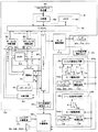
次に、図8を参照して、主制御回路61、副制御回路62、主制御回路61又は副制御回路62に電気的に接続する周辺装置(アクチュエータ)を含む遊技機1の回路構成について説明する。なお、図8は、遊技機1の回路構成を示す図である。   Next, the circuit configuration of the gaming machine 1 including a peripheral device (actuator) electrically connected to the main control circuit 61, the sub control circuit 62, the main control circuit 61 or the sub control circuit 62 will be described with reference to FIG. To do. FIG. 8 is a diagram showing a circuit configuration of the gaming machine 1.

主制御回路61は、マイクロコンピュータ63を主たる構成要素とし、これに乱数サンプリング回路等を加えた構成となっている。マイクロコンピュータ63は、メインCPU64、記憶手段であるROM65及びRAM66により構成されている。メインCPU64には、クロックパルス発生器67、分周器68、乱数発生器69、サンプリング回路70及び周辺装置との間で信号を授受するI/Oポート(入出力ポート)71が接続されている。   The main control circuit 61 includes a microcomputer 63 as a main component, and a random number sampling circuit and the like are added to the main component. The microcomputer 63 includes a main CPU 64 and ROM 65 and RAM 66 as storage means. The main CPU 64 is connected to an I / O port (input / output port) 71 that exchanges signals with a clock pulse generator 67, a frequency divider 68, a random number generator 69, a sampling circuit 70, and peripheral devices. .

メインCPU64は、所定の確率で内部当籤役を決定し、当該内部当籤役と停止操作が検出されたこととに基づいて、メインリール2〜4の回転を停止させる。また、メインCPU64は、メインリール2〜4回転を停止させた際に、図柄表示領域39に表示された図柄の組合せに基づいて、役が成立したか否かを判別して成立している場合に、当該成立した役に応じてメダルを払い出す。   The main CPU 64 determines an internal winning combination with a predetermined probability, and stops the rotation of the main reels 2 to 4 based on the detection of the internal winning combination and the stop operation. When the main CPU 64 determines whether or not a winning combination has been established based on the symbol combination displayed in the symbol display area 39 when the main reels 2 to 4 have stopped rotating. Then, medals are paid out according to the established combination.

なお、本実施形態のメインCPU64は、本発明の当籤役決定手段及び停止制御手段を構成する。   The main CPU 64 of this embodiment constitutes a winning combination determining unit and a stop control unit of the present invention.

クロックパルス発生器67及び分周器68は、基準クロックパルスを発生する。乱数発生器69は、「0」〜「65535」の範囲の乱数を発生する。サンプリング回路70は、乱数発生器69により発生された乱数から1つの乱数値を抽出(サンプリング)する。   The clock pulse generator 67 and the frequency divider 68 generate a reference clock pulse. The random number generator 69 generates a random number in the range of “0” to “65535”. The sampling circuit 70 extracts (samples) one random number value from the random number generated by the random number generator 69.

また、遊技機1では、抽出した乱数値をRAM66の乱数値記憶領域に記憶する。そして、毎回の遊技ごとにRAM66の乱数値記憶領域に記憶された乱数値に基づいて、後述の内部抽籤処理(図48、図49参照)、及びロック抽籤処理(図50参照)において内部当籤役、及びロック情報の決定を行う。   In the gaming machine 1, the extracted random number value is stored in the random value storage area of the RAM 66. Then, based on the random number value stored in the random number storage area of the RAM 66 for each game, an internal winning combination in an internal lottery process (see FIGS. 48 and 49) and a lock lottery process (see FIG. 50) described later. And determination of lock information.

なお、乱数サンプリングのための手段として、マイクロコンピュータ63内で、即ちメインCPU64の動作プログラム上で、乱数サンプリングを実行する構成にしてもよい。その場合、乱数発生器69及びサンプリング回路70は省略可能であり、或いは、乱数サンプリング動作のバックアップ用として残しておくことも可能である。   In addition, as a means for random number sampling, you may make it the structure which performs random number sampling within the microcomputer 63, ie, on the operation program of the main CPU64. In that case, the random number generator 69 and the sampling circuit 70 can be omitted, or can be left as a backup for the random number sampling operation.

マイクロコンピュータ63のROM65には、メインCPU64の処理に係るプログラム(例えば、後述の図44〜図57参照)、各種テーブル(例えば、図4、図7、後述の図10〜図18、図20〜図22、図24参照)、副制御回路62へ送信するための各種制御指令(コマンド)などが記憶されている。   In the ROM 65 of the microcomputer 63, a program (for example, see FIGS. 44 to 57 described later) and various tables (for example, FIGS. 4 and 7, FIGS. 10 to 18 and 20 to 20 described later) are stored. 22 and 24), various control commands (commands) to be transmitted to the sub control circuit 62 are stored.

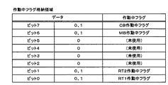
RAM66には、メインCPU64の処理により得られる種々の情報がセットされる。例えば、抽出した乱数値、設定値、遊技状態情報、作動状態情報、払出枚数、ボーナス持越状況などを特定する情報、各種カウンタ及びフラグがセットされている。これらの情報の一部は、前述のコマンドにより副制御回路62に送信される。   Various information obtained by processing of the main CPU 64 is set in the RAM 66. For example, the extracted random number value, setting value, gaming state information, operating state information, payout number, information specifying the bonus carryover status, various counters and flags are set. Some of these pieces of information are transmitted to the sub-control circuit 62 by the above-described command.

図8の回路において、マイクロコンピュータ63からの制御信号により動作が制御される主要なアクチュエータとしては、ステッピングモータ45L、45C、45R、各種ランプ(BETランプ13〜15、スタートランプ25、WINランプ26、インサートランプ27)、各種表示部(貯留枚数表示部17、払出枚数表示部16)、メダルを収納するホッパー72などがある。   In the circuit of FIG. 8, the main actuators whose operation is controlled by a control signal from the microcomputer 63 include stepping motors 45L, 45C, 45R, various lamps (BET lamps 13-15, start lamp 25, WIN lamp 26, Insert lamp 27), various display units (stored number display unit 17, payout number display unit 16), hopper 72 for storing medals, and the like.

ステッピングモータ45L、45C、45Rは、モータ駆動回路73によって駆動制御され、メインリール2〜4のリールドラムを回転させる。モータ駆動回路73は、I/Oポート71を介して受信するメインCPU64からの制御信号に基づいて、各メインリール2〜4を回転駆動させたり停止させたりする。なお、本実施形態のステッピングモータ45L、45C、45Rは、本発明の図柄変動手段を構成する。   The stepping motors 45L, 45C, and 45R are driven and controlled by the motor drive circuit 73, and rotate the reel drums of the main reels 2 to 4. The motor drive circuit 73 rotates and stops the main reels 2 to 4 based on a control signal from the main CPU 64 received via the I / O port 71. Note that the stepping motors 45L, 45C, and 45R of the present embodiment constitute the symbol variation means of the present invention.

各種ランプ(BETランプ13〜15、スタートランプ25、WINランプ26、インサートランプ27)は、各ランプ駆動回路74によって駆動制御される。各ランプ駆動回路74は、I/Oポート71を介して受信するメインCPU64からの制御信号に基づいて、各種ランプを点灯させたり消灯させたりする。   Various lamps (BET lamps 13 to 15, start lamp 25, WIN lamp 26, insert lamp 27) are driven and controlled by each lamp driving circuit 74. Each lamp drive circuit 74 turns on and off various lamps based on a control signal from the main CPU 64 received via the I / O port 71.

各種表示部(貯留枚数表示部17、払出枚数表示部16)は、各表示部駆動回路75によって駆動制御される。各表示部駆動回路75は、I/Oポート71を介して受信するメインCPU64からの制御信号に基づいて、貯留枚数表示部17、払出枚数表示部16に数値を表示させたりする。   The various display units (the stored number display unit 17 and the payout number display unit 16) are driven and controlled by each display unit drive circuit 75. Each display unit drive circuit 75 displays numerical values on the stored number display unit 17 and the payout number display unit 16 based on a control signal from the main CPU 64 received via the I / O port 71.

ホッパー72は、ホッパー駆動回路76によって駆動制御される。ホッパー駆動回路76は、I/Oポート71を介して受信するメインCPU64からの制御信号に基づいて、ホッパーから所定枚数のメダルを払い出させる。   The hopper 72 is driven and controlled by a hopper drive circuit 76. The hopper driving circuit 76 pays out a predetermined number of medals from the hopper based on a control signal from the main CPU 64 received via the I / O port 71.

また、マイクロコンピュータ63の入力部には、前述の各回路及び各アクチュエータに制御信号を出力する契機となる入力信号を発生する各スイッチ及び各回路が接続されている。各スイッチ及び各回路としては、投入メダルセンサ9S、スタートスイッチ33S、貯留メダル投入スイッチ30S〜32S、貯留メダル精算スイッチ37S、リセットスイッチ55S、設定スイッチ56S、リール位置検出回路77、ストップスイッチ78LS、78CS、78RS、払出完了信号回路79がある。   In addition, each switch and each circuit for generating an input signal that triggers the output of a control signal to each circuit and each actuator are connected to the input unit of the microcomputer 63. As each switch and each circuit, the inserted medal sensor 9S, the start switch 33S, the stored medal insertion switches 30S to 32S, the stored medal settlement switch 37S, the reset switch 55S, the setting switch 56S, the reel position detection circuit 77, the stop switches 78LS, 78CS. , 78RS, and a payout completion signal circuit 79.

投入メダルセンサ9Sは、遊技者の投入操作によりメダル投入口9に投入されたメダルを検出し、メダルが投入されたことを示す投入検出信号をI/Oポート71を介してマイクロコンピュータ63に送信する。   The insertion medal sensor 9S detects a medal inserted into the medal insertion slot 9 by the player's insertion operation, and transmits an insertion detection signal indicating that a medal has been inserted to the microcomputer 63 via the I / O port 71. To do.

スタートスイッチ33Sは、スタートレバー33に対する遊技者の開始操作を検出し、遊技の開始を指令する開始信号をマイクロコンピュータ63に送信する。   The start switch 33S detects the start operation of the player with respect to the start lever 33, and transmits a start signal instructing the start of the game to the microcomputer 63.

貯留メダル投入スイッチ30S〜32Sは、1貯留メダル投入ボタン30、2貯留メダル投入ボタン31、及び3貯留メダル投入ボタン32に対する遊技者の投入操作を検出し、クレジットされたメダルから、1枚、2枚又は3枚のメダルの投入を指令する貯留投入信号をマイクロコンピュータ63に送信する。   The stored medal insertion switches 30S to 32S detect the player's input operation for the 1 stored medal insertion button 30, the 2 stored medal insertion button 31, and the 3 stored medal insertion button 32. A storage input signal for instructing insertion of three or three medals is transmitted to the microcomputer 63.

貯留メダル精算スイッチ37Sは、貯留メダル精算ボタン37に対する遊技者の切り替え操作を検出し、クレジットモード又は払出モードを切り替えるための払出切替信号をマイクロコンピュータ63に出力する。また、クレジットモードから払出モードに切り替えられた場合、遊技機1にクレジットされているメダルの払い出しを指令する信号をマイクロコンピュータ63に送信する。   The stored medal settlement switch 37 </ b> S detects a player switching operation on the stored medal settlement button 37 and outputs a payout switching signal for switching between the credit mode or the payout mode to the microcomputer 63. When the credit mode is switched to the payout mode, a signal instructing the payout of medals credited to the gaming machine 1 is transmitted to the microcomputer 63.

設定スイッチ56S及びリセットスイッチ55Sは、遊技機の管理者による設定値変更操作を検出することにより、RAM66の設定値を更新させるための設定更新信号をマイクロコンピュータ63に送信する。   The setting switch 56 </ b> S and the reset switch 55 </ b> S transmit a setting update signal for updating the setting value of the RAM 66 to the microcomputer 63 by detecting a setting value changing operation by the administrator of the gaming machine.

設定値を更新するためには、まず電源スイッチ(図示しない)を一旦オフにした後、設定スイッチ56Sをオンにした状態で電源スイッチをオンにする。   In order to update the set value, first, a power switch (not shown) is first turned off, and then the power switch is turned on while the setting switch 56S is turned on.

当該操作により、RAM66に記憶された設定値がクリアされる。また、遊技機1の前面に設けられた表示部には、現時点における設定値が表示される。現時点における設定値の表示は、払出枚数表示部16により行われる。   By this operation, the set value stored in the RAM 66 is cleared. Further, the set value at the present time is displayed on the display unit provided on the front surface of the gaming machine 1. The currently set value is displayed by the payout number display unit 16.

この状態において、リセットスイッチ55Sを操作する毎に、設定値が「1」〜「H」まで順次増加するとともに循環して表示される。   In this state, every time the reset switch 55S is operated, the set value sequentially increases from “1” to “H” and is displayed in a circulating manner.

このようにして、設定値を選択した後、スタートレバー33を操作することにより、設定値を確定させる。   In this way, after the set value is selected, the set value is confirmed by operating the start lever 33.

つぎに、設定スイッチ56Sをオフにすると、設定値が一時的に保持され、RAM66がクリアされた後、一時的に保持された設定値がRAM66に再記憶される。   Next, when the setting switch 56S is turned off, the setting value is temporarily held. After the RAM 66 is cleared, the temporarily holding setting value is stored again in the RAM 66.

設定値の設定中には、C/Pスイッチ14Sが遊技メダルを返却する状態に切り替えられており、設定値を確定させた後に、払出枚数表示部16の表示が消灯し、貯留枚数表示部17に「0」が表示されると、遊技機1における遊技を開始することができる。   During the setting of the set value, the C / P switch 14S is switched to a state in which the game medal is returned. After the set value is confirmed, the payout number display unit 16 is turned off and the stored number display unit 17 is displayed. When “0” is displayed, the game on the gaming machine 1 can be started.

また、設定値は、「1」、「4」、「6」、「H」の4段階に設定することができ、当該設定値に基づいて、後述する内部抽籤テーブルを選択することにより、小役、及びMBが内部当籤役に決定される確率を変化させる。また、設定値の変更が行なわれることで、RAM66領域に記憶されている遊技状態情報はクリアされる。   In addition, the set value can be set in four stages of “1”, “4”, “6”, and “H”, and by selecting an internal lottery table to be described later based on the set value, a small value can be set. The probabilities and the probability that MB is determined to be an internal winning combination are changed. Further, the game state information stored in the RAM 66 area is cleared by changing the set value.

また、設定スイッチ56Sをオフにした状態で、リセットスイッチ55Sを操作することによりRAM66領域に記憶されている各種情報(遊技状態等)がクリアされる。   Further, by operating the reset switch 55S with the setting switch 56S turned off, various information (such as gaming state) stored in the RAM 66 area is cleared.

リール位置検出回路77は、メインリール2〜4の回転が開始された後に、各ステッピングモータ45L、45C、45Rに供給される駆動パルスを受信し、駆動パルス信号をI/Oポート71を介してマイクロコンピュータ63に送信する。また、リール位置検出回路77は、各メインリール2〜4の駆動機構内部に含まれるフォトセンサー(図示しない)が各メインリール2〜4に設けられた基準位置を検出する度に出力するリセットパルスを受信し、リセットパルス信号をI/Oポート71を介してマイクロコンピュータ63に送信する。マイクロコンピュータ63のメインCPU64は、駆動パルス信号の受信に基づいてRAM66の後述するパルスカウンタや図柄カウンタを更新し、リセットパルス信号の受信に基づいて当該パルスカウンタや図柄カウンタに「0」をセットする。これにより、メインCPU64は、図柄カウンタに基づいてメインリール2〜4の各図柄位置を判別することができる。   The reel position detection circuit 77 receives drive pulses supplied to the stepping motors 45L, 45C and 45R after the rotation of the main reels 2 to 4 is started, and sends the drive pulse signal via the I / O port 71. It transmits to the microcomputer 63. The reel position detection circuit 77 outputs a reset pulse every time a photo sensor (not shown) included in the drive mechanism of each main reel 2 to 4 detects a reference position provided on each main reel 2 to 4. And a reset pulse signal is transmitted to the microcomputer 63 via the I / O port 71. The main CPU 64 of the microcomputer 63 updates a pulse counter and a symbol counter (to be described later) of the RAM 66 based on reception of the drive pulse signal, and sets “0” to the pulse counter and symbol counter based on reception of the reset pulse signal. . Thereby, the main CPU 64 can determine the symbol positions of the main reels 2 to 4 based on the symbol counter.

ストップスイッチ78LS、78CS、78RSは、それぞれストップボタン34、35、36に対する遊技者の停止操作を検出し、検出したストップボタン34〜36に対応するメインリール2〜4の回転の停止を指令する停止信号をI/Oポート71を介してマイクロコンピュータ63に送信する。なお、本実施形態のストップスイッチ78LS、78CS、78RSは、本発明の停止操作検出手段を構成する。   Stop switches 78LS, 78CS, and 78RS detect the player's stop operation on the stop buttons 34, 35, and 36, respectively, and stop that instructs the stop of rotation of the main reels 2 to 4 corresponding to the detected stop buttons 34 to 36, respectively. The signal is transmitted to the microcomputer 63 via the I / O port 71. Note that the stop switches 78LS, 78CS, and 78RS of the present embodiment constitute stop operation detecting means of the present invention.

払出完了信号回路79は、メダル検出部72Sにより検出されたメダルの枚数(即ちホッパー72から払い出されたメダルの枚数)が指定された枚数に達した際に、メダルの払い出しが完了したことを示すための払出完了信号をI/Oポート71を介してマイクロコンピュータ63に送信する。   The payout completion signal circuit 79 indicates that the medal payout has been completed when the number of medals detected by the medal detection unit 72S (that is, the number of medals paid out from the hopper 72) reaches the designated number. A payout completion signal for indicating is sent to the microcomputer 63 via the I / O port 71.

I/Oポート71には、サブ制御部通信ポート80が接続されており、メインCPU64は、主制御回路61に設けられているサブ制御部通信ポート80から、副制御回路62へ各種コマンドなどの信号を送信する。なお、図8及び図9に示すように、サブ制御部通信ポート80から送信された信号は、メインサブ中継基板97、サブ中継基板98、メイン制御部通信ポート88を介して副制御回路62に設けられているメイン制御部通信ポート88に受信される。副制御回路62では、主制御回路61から送信された各種コマンドなどの信号に基づいて演出に係る各種処理を行う。なお、副制御回路62から主制御回路61へコマンド、情報等が送信されることはなく、主制御回路61から副制御回路62への一方向通信のみ行われる。副制御回路62の構成の詳細については、後述する。   A sub-control unit communication port 80 is connected to the I / O port 71, and the main CPU 64 sends various commands to the sub-control circuit 62 from the sub-control unit communication port 80 provided in the main control circuit 61. Send a signal. 8 and 9, the signal transmitted from the sub control unit communication port 80 is sent to the sub control circuit 62 via the main sub relay board 97, the sub relay board 98, and the main control unit communication port 88. The data is received by the main control unit communication port 88 provided. The sub control circuit 62 performs various processes related to effects based on signals such as various commands transmitted from the main control circuit 61. Note that commands, information, and the like are not transmitted from the sub control circuit 62 to the main control circuit 61, and only one-way communication from the main control circuit 61 to the sub control circuit 62 is performed. Details of the configuration of the sub-control circuit 62 will be described later.

遊技機1では、メダルの投入を条件に、遊技者のスタートレバー33に対する開始操作によって、スタートスイッチ33Sから遊技を開始する開始信号が送信されると、モータ駆動回路73に制御信号が送信され、ステッピングモータ45L、45C、45Rの駆動制御(例えば、各相への励磁など)によりメインリール2〜4の回転が開始される。   In the gaming machine 1, when a start signal for starting a game is transmitted from the start switch 33S by a start operation on the start lever 33 by the player on condition that a medal is inserted, a control signal is transmitted to the motor drive circuit 73, The rotation of the main reels 2 to 4 is started by drive control of the stepping motors 45L, 45C, and 45R (for example, excitation to each phase).

メインリール2〜4の回転が開始されると、上述したようにメインリール2〜4の回転に伴って、RAM66上に設けられた各メインリール2〜4に対応するパルスカウンタ及び図柄カウンタが更新される。具体的には、遊技機1では、パルスカウンタにより「16」のパルスが計数される毎に、図柄カウンタの値が「1」ずつ更新される。ここで、図柄カウンタの値が「1」更新されることは、対応するメインリール2〜4が図柄1コマ分(各図柄が一図柄分移動する距離を1コマとする)回転したことに対応しており、また、図柄配置テーブル(メインリール)における図柄位置「00」の図柄が図柄表示領域39の中段領域に表示されたときに、図柄カウンタの値が「0」となるように設定されている。例えば、左メインリールの図柄位置「13」の赤リンゴ図柄が図柄表示領域39の左・中段領域39LMに表示されたときには、左メインリール2に対応する図柄カウンタの値は「13」となっている。なお、図柄カウンタの値とメインリール2〜4の回転位置とが徐々にずれを生じるため、メインCPU64はリセットパルス信号の受信に基づいてメインリール2〜4の1回転毎にパルスカウンタや図柄カウンタに「0」をセットすることにより、当該ずれによる誤作動を防止している。   When the rotation of the main reels 2 to 4 is started, the pulse counter and the symbol counter corresponding to each of the main reels 2 to 4 provided on the RAM 66 are updated with the rotation of the main reels 2 to 4 as described above. Is done. Specifically, in the gaming machine 1, the value of the symbol counter is updated by “1” every time “16” pulses are counted by the pulse counter. Here, when the value of the symbol counter is updated by “1”, the corresponding main reels 2 to 4 are rotated by one frame of symbols (the distance that each symbol moves by one symbol is one frame). In addition, when the symbol at the symbol position “00” in the symbol arrangement table (main reel) is displayed in the middle area of the symbol display area 39, the symbol counter value is set to “0”. ing. For example, when the red apple symbol at the symbol position “13” of the left main reel is displayed in the left / middle area 39LM of the symbol display area 39, the value of the symbol counter corresponding to the left main reel 2 is “13”. Yes. Since the value of the symbol counter and the rotational position of the main reels 2 to 4 are gradually shifted, the main CPU 64 receives a reset pulse signal and the pulse counter or symbol counter for each rotation of the main reels 2 to 4. By setting “0” to, malfunction due to the deviation is prevented.

また、スタートスイッチ33Sから開始信号が送信されると、乱数発生器69やサンプリング回路70により乱数値が抽出される。遊技機1では、乱数値が抽出されると、RAM66の乱数値記憶領域に記憶される。そして、乱数値記憶領域に記憶された乱数値に基づいて内部当籤役、後述の開始時ロック情報及び終了時ロック情報が決定される。   When a start signal is transmitted from the start switch 33S, a random number value is extracted by the random number generator 69 and the sampling circuit 70. In the gaming machine 1, when the random value is extracted, it is stored in the random value storage area of the RAM 66. Then, based on the random value stored in the random value storage area, the internal winning combination, start lock information and end lock information described later are determined.

メインリール2〜4が定速回転に達した後、遊技者のストップボタン34〜36に対する停止操作によって、ストップスイッチ78LS、78CS、78RSから停止信号が送信されると、当該停止信号及び決定された内部当籤役に基づいて、メインリール2〜4を停止制御する制御信号がモータ駆動回路73に送信される。モータ駆動回路73はステッピングモータ45L、45C、45Rを駆動制御し、メインリール2〜4の回転を停止させる。   When a stop signal is transmitted from the stop switches 78LS, 78CS, and 78RS by a stop operation on the stop buttons 34 to 36 of the player after the main reels 2 to 4 reach constant speed rotation, the stop signal and the determined signal are determined. A control signal for stopping and controlling the main reels 2 to 4 is transmitted to the motor drive circuit 73 based on the internal winning combination. The motor drive circuit 73 drives and controls the stepping motors 45L, 45C, and 45R, and stops the rotation of the main reels 2 to 4.

ここで、遊技機1は、停止操作が行われた時点から内部当籤役の成立に係る図柄を最大滑りコマ数分、すなわち、3コマ分引き込んでメインリールの回転を停止させる。具体的には、遊技機1は、ストップスイッチ78LS、78CS、78RSにより停止操作の検出が行われた後、3コマ以内に内部当籤役の成立に係る図柄が存在するか否かを判別し、3コマ以内に内部当籤役の成立に係る図柄が存在する場合に、当該図柄を有効ライン上に停止表示されるように滑りコマ数を決定し、該当するメインリールを停止させる。ここで、遊技機1は、内部当籤役として複数の役を決定した場合において、3コマ以内に内部当籤役の成立に係る図柄が複数存在する場合には、より優先順位の高い内部当籤役に係る図柄を有効ライン上に停止表示させるように滑りコマ数を決定する。ここで、優先順位1位(優先度が最も高い)はリプレイに係る図柄の組合せであり、優先順位2位はボーナス(MB)に係る図柄の組合せである。次いで、優先順位3位は小役に係る図柄の組合せである。なお、ストップスイッチ78LS、78CS、78RSにより停止操作の検出された際、該当するメインリールの図柄カウンタに対応する図柄位置、すなわち、メインリールの回転の停止が開始される図柄位置を「停止開始位置」といい、当該停止開始位置に決定した滑りコマ数(数値範囲「0」〜「3」)を加算した図柄位置、すなわち、メインリールの回転を停止させる図柄位置を「停止予定位置」という。また、滑りコマ数は、ストップスイッチ78LS、78CS、78RSにより停止操作が検出されてから対応するメインリールの回転が停止するまでのリールの回転量であり、遊技機1では、最大滑りコマ数を「3」と規定している。   Here, the gaming machine 1 stops the rotation of the main reel by drawing the symbols related to the establishment of the internal winning combination for the maximum number of sliding symbols, that is, three frames from the time when the stop operation is performed. Specifically, the gaming machine 1 determines whether or not there is a symbol related to the establishment of an internal winning combination within three frames after the stop operation is detected by the stop switches 78LS, 78CS, and 78RS. When there is a symbol related to the establishment of the internal winning combination within three frames, the number of sliding symbols is determined so that the symbol is stopped and displayed on the active line, and the corresponding main reel is stopped. Here, in the case where a plurality of winning combinations are determined as internal winning combinations, the gaming machine 1 has a higher priority internal winning combination if there are multiple symbols related to the establishment of the internal winning combination within 3 frames. The number of sliding frames is determined so that the symbol is stopped and displayed on the active line. Here, the first priority (the highest priority) is a symbol combination related to replay, and the second priority is a symbol combination related to a bonus (MB). Next, the third highest priority is a combination of symbols related to a small combination. When the stop operation is detected by the stop switches 78LS, 78CS, and 78RS, the symbol position corresponding to the symbol counter of the corresponding main reel, that is, the symbol position at which the rotation of the main reel starts to be stopped is referred to as “stop start position”. The symbol position obtained by adding the determined number of sliding symbols (numerical range “0” to “3”) to the stop start position, that is, the symbol position at which the rotation of the main reel is stopped is referred to as “scheduled stop position”. The number of sliding symbols is the amount of reel rotation from when the stop operation is detected by the stop switches 78LS, 78CS, 78RS until the corresponding main reel stops rotating. It is defined as “3”.

全てのメインリール2〜4の回転が停止すると、有効ライン上に表示された図柄の組合せに基づいて表示役の検索処理、すなわち、役の成立・不成立の判定が行われる。表示役の検索は、ROM65に記憶された図柄組合せテーブル(図22参照)に基づいて行われる。この図柄組合せテーブルでは、表示役に係る図柄の組合せと、対応する配当とが設定されている。   When the rotations of all the main reels 2 to 4 are stopped, the display combination search process, that is, the determination of whether the combination is established or not is performed based on the combination of symbols displayed on the effective line. The search for the display combination is performed based on the symbol combination table (see FIG. 22) stored in the ROM 65. In this symbol combination table, a symbol combination related to a display combination and a corresponding payout are set.

表示役の検索により、入賞に係る図柄の組合せが表示されたと判別されると、ホッパー駆動回路76に制御信号が出力され、ホッパー72の駆動によりメダルの払い出しが行われる。この際、メダル検出部72Sは、ホッパー72から払い出されるメダルの枚数を計数し、その計数値が指定された数に達すると、払出完了信号回路79により払出完了信号が送信される。これにより、ホッパー駆動回路76に制御信号が送信され、ホッパー72の駆動が停止される。   When it is determined by the display combination search that a combination of symbols related to winning is displayed, a control signal is output to the hopper drive circuit 76 and the hopper 72 is driven to pay out medals. At this time, the medal detection unit 72S counts the number of medals to be paid out from the hopper 72, and when the count value reaches a designated number, a payout completion signal circuit 79 transmits a payout completion signal. Thereby, a control signal is transmitted to the hopper drive circuit 76, and the drive of the hopper 72 is stopped.

なお、貯留メダル精算スイッチ37Sにより、クレジットモードに切り替えられている場合には、入賞に係る図柄の組合せが表示されたと判別されると、入賞に係る図柄の組合せに応じた払出枚数をRAM66のクレジット数カウンタに加算する。また、各表示部駆動回路75に制御信号が出力され、クレジット数カウンタの値が貯留枚数表示部17に表示される。ここで、入賞に係る図柄の組合せが表示された場合に行われる、メダルの払い出し又はクレジットを総称して単に「払い出し」という場合がある。   When the stored medal settlement switch 37S is switched to the credit mode, if it is determined that the symbol combination related to winning is displayed, the payout number corresponding to the symbol combination related to winning is credited to the RAM 66. Add to the number counter. In addition, a control signal is output to each display unit driving circuit 75, and the value of the credit number counter is displayed on the stored number display unit 17. Here, there is a case where a medal payout or a credit performed when a symbol combination related to winning is displayed is simply referred to as “payout”.

次に、図9を参照して、副制御回路62の回路構成について説明する。なお、図9は、遊技機1の副制御回路の回路構成を示す図である。   Next, the circuit configuration of the sub-control circuit 62 will be described with reference to FIG. FIG. 9 is a diagram showing a circuit configuration of the sub control circuit of the gaming machine 1.

副制御回路62は、主制御回路61からの各種コマンドなどの信号に基づいて、映像、音、光又はメインリールの動作等による遊技に関する演出を行うための制御を行う。副制御回路62は、マイクロコンピュータ81を主たる構成要素として構成されている。マイクロコンピュータ81は、サブCPU82、記憶手段であるROM83及びRAM84により構成されている。サブCPU82には、クロックパルス発生器85、分周器86及び周辺装置との間で信号を授受するI/Oポート(入出力ポート)87が接続されている。また、マイクロコンピュータ81は、I/Oポート87を介してランプ駆動回路110、音源IC91、パワーアンプ92、分断回路93が接続されている。   Based on signals such as various commands from the main control circuit 61, the sub-control circuit 62 performs control for performing effects related to the game by video, sound, light, main reel operation, or the like. The sub-control circuit 62 is configured with the microcomputer 81 as a main component. The microcomputer 81 includes a sub CPU 82 and ROM 83 and RAM 84 which are storage means. The sub CPU 82 is connected to an I / O port (input / output port) 87 that exchanges signals with the clock pulse generator 85, the frequency divider 86, and peripheral devices. Further, the microcomputer 81 is connected to the lamp driving circuit 110, the sound source IC 91, the power amplifier 92, and the dividing circuit 93 via the I / O port 87.

ROM83には、サブCPU82の処理に係るプログラム(例えば、後述の図58〜図72参照)、停止テーブルなどの各種テーブルなどが記憶されている。   The ROM 83 stores programs related to the processing of the sub CPU 82 (for example, see FIGS. 58 to 72 described later), various tables such as a stop table, and the like.

RAM84には、主制御回路61における内部当籤役格納領域と同様の領域が、内部当籤役格納領域(サブ)として確保されている。また、スタートコマンドに含まれる主制御回路61における内部当籤役格納領域のボーナスに対応するビットがオンである場合に、RAM84のMB持越フラグがオンとされ、副制御回路62においてMB持越状態であるか否かを判別することができる。   In the RAM 84, an area similar to the internal winning combination storing area in the main control circuit 61 is secured as an internal winning combination storing area (sub). Further, when the bit corresponding to the bonus in the internal winning combination storing area in the main control circuit 61 included in the start command is on, the MB carryover flag of the RAM 84 is turned on, and the sub control circuit 62 is in the MB carryover state. It can be determined whether or not.

サブCPU82は、演出に係る制御処理を所定の処理手順にしたがって行う。所定の処理手順は、シーケンスプログラムとしてROM83に記憶されている。サブCPU82には、アドレスバス切離回路89及びデータバス切離回路90が接続されており、アドレスバス切離回路89はアドレスバスを介してROM83に接続されており、データバス切離回路90は、データバスを介してROM83に接続されている。   The sub CPU 82 performs a control process related to the effect according to a predetermined processing procedure. The predetermined processing procedure is stored in the ROM 83 as a sequence program. An address bus disconnect circuit 89 and a data bus disconnect circuit 90 are connected to the sub CPU 82. The address bus disconnect circuit 89 is connected to the ROM 83 via the address bus. Are connected to the ROM 83 via a data bus.

サブCPU82は、ROM83に記憶されている情報を読み出すときには、ROM83のチップセレクト端子SにI/Oポート87を介してロウレベル信号を送信し、次いで、アドレスバス切離回路89及びデータバス切離回路90の出力イネーブル端子EにI/Oポート87を介してロウレベル信号を送信する。アドレスバス切離回路89及びデータバス切離回路90は、それぞれの出力イネーブル端子Eにハイレベル信号が入力されているときには、データ出力端子がハイインピーダンス状態となって、サブCPU82とROM83間は電気的に絶縁状態となる。これにより、サブCPU82からアドレスバス切離回路89及びデータバス切離回路90の各データ入力端子に入力されるアドレスバスデータ及びデータバスデータは、アドレスバス切離回路89及びデータバス切離回路90の各データ出力端子から出力されない。一方、アドレスバス切離回路89及びデータバス切離回路90は、それぞれの出力イネーブル端子Eにロウレベル信号が入力されているときには、サブCPU82からアドレスバス切離回路89及びデータバス切離回路90の各データ入力端子に入力されたアドレスバスデータ及びデータバスデータは、各データ出力端子からそのまま出力される。サブCPU82は、このようにして、アドレスバス及びデータバスを介してROM83に対して情報読み出しアクセスを行う。   When reading the information stored in the ROM 83, the sub CPU 82 transmits a low level signal to the chip select terminal S of the ROM 83 via the I / O port 87, and then the address bus disconnect circuit 89 and the data bus disconnect circuit. A low level signal is transmitted to the 90 output enable terminals E via the I / O port 87. In the address bus disconnection circuit 89 and the data bus disconnection circuit 90, when a high level signal is input to each output enable terminal E, the data output terminal is in a high impedance state and the sub CPU 82 and the ROM 83 are electrically connected. Insulative state. As a result, the address bus data and the data bus data input from the sub CPU 82 to the data input terminals of the address bus disconnection circuit 89 and the data bus disconnection circuit 90 are the address bus disconnection circuit 89 and the data bus disconnection circuit 90. Not output from each data output terminal. On the other hand, the address bus disconnection circuit 89 and the data bus disconnection circuit 90 are connected to the address bus disconnection circuit 89 and the data bus disconnection circuit 90 from the sub CPU 82 when a low level signal is input to each output enable terminal E. The address bus data and data bus data input to each data input terminal are output as they are from each data output terminal. In this way, the sub CPU 82 performs information read access to the ROM 83 via the address bus and the data bus.

サブCPU82は、後述するように、主制御回路61のメインCPU64によって3択役群L、3択役群C、3択役群Rが内部当籤役として決定された場合に、3択役群L、3択役群C、3択役群Rに係る図柄の組合せを図柄表示領域39に表示させるためリールバックランプ48a〜48cのうち正解リールに対応するバックランプのみを点灯させることにより、当籤役補助情報を遊技者に報知するAT遊技状態を作動させるか否かと、当該AT遊技状態を継続させる期間の基となるATセット数(仮ATセット数)とを、所定の確率に基づいて決定し、AT遊技状態を作動させることを決定した場合に、ステップS404の処理において図柄表示態様を表示するサブリール図柄表示領域5A、6A、7Aに特別表示態様を表示させることを許可するか否かと、ステップS409の処理において複数ある当該特別表示態様の中から何れの特別表示態様を当該サブリール図柄表示領域5A、6A、7Aに表示させるかとを、所定の確率で決定する。サブCPU82は、ステップS404の処理でサブリール図柄表示領域5A、6A、7Aに特別表示態様を表示させることを許可した場合であって、所定のタイミングで停止操作が検出されたときに、ステップS406の処理で決定した特別表示態様を当該サブリール図柄表示領域5A、6A、7Aに表示させ、サブリール図柄表示領域5A、6A、7Aに特別表示態様を表示させたことに基づいて、決定したATセット数が消化されるまでの期間、AT遊技状態を作動させるとともに、4thリール8を回転制御して図柄表示領域51に「7RUSH」を表示させることによりAT遊技状態が作動していることを報知する。また、サブCPU82は、AT遊技状態を作動させている際に、3択役群L、3択役群C、3択役群Rが内部当籤役として決定された場合に、正解リールに対応するバックランプのみを点灯させることにより当籤役補助情報を報知する。また、サブCPU82は、決定したATセット数(仮ATセット数)に応じて、サブリール図柄表示領域5A、6A、7Aに表示させる特別表示態様を決定する。   As will be described later, the sub-CPU 82 determines that the 3-choice role group L, the 3-choice role group C, and the 3-choice role group R are determined as internal winning combinations by the main CPU 64 of the main control circuit 61. In order to display the combination of symbols related to the three-choice role group C and the three-choice role group R in the symbol display area 39, only the back lamp corresponding to the correct reel among the reel back lamps 48a to 48c is turned on. Based on a predetermined probability, whether or not to activate the AT gaming state for notifying the player of auxiliary information and the number of AT sets (temporary AT set number) as a basis for a period for continuing the AT gaming state is determined. When it is decided to activate the AT gaming state, the special display mode is displayed in the sub-reel symbol display areas 5A, 6A, and 7A for displaying the symbol display mode in the process of step S404. And whether or not to permit, the sub reel symbol display area 5A of any special display mode from among a plurality of the special display mode in the processing of step S409, 6A, transient to be displayed on 7A, determined with a predetermined probability. The sub CPU 82 permits the display of the special display mode in the sub reel symbol display areas 5A, 6A, and 7A in the process of step S404, and when a stop operation is detected at a predetermined timing, the sub CPU 82 The special display mode determined in the process is displayed in the sub-reel symbol display areas 5A, 6A, and 7A, and the special display mode is displayed in the sub-reel symbol display areas 5A, 6A, and 7A. During the period until digestion, the AT gaming state is activated, and the 4th reel 8 is rotationally controlled to display “7RUSH” in the symbol display area 51 to notify that the AT gaming state is activated. Further, the sub CPU 82 corresponds to the correct reel when the three-choice role group L, the three-choice role group C, and the three-choice role group R are determined as the internal winning combinations when the AT gaming state is activated. The winning combination assistance information is notified by turning on only the back lamp. Further, the sub CPU 82 determines a special display mode to be displayed in the sub reel symbol display areas 5A, 6A, and 7A according to the determined AT set number (temporary AT set number).

また、サブCPU82は、後述するように、スタートコマンドを受信することによりサブリール5〜7を回転させ、リール停止コマンドと停止テーブルとに基づいてサブリール5〜7の回転を停止させる。また、サブCPU82は、ATセット数カウンタの値が「2」以上である場合に、AT報知回数カウンタの値が「0」になるという条件が充足されたことに基づいて、AT遊技状態の作動を中断させ、再度、サブリール図柄表示領域5A、6A、7Aに特別表示態様を表示させたことに基づいて、AT遊技状態の作動を再開させる。また、サブCPU82は、AT遊技状態の作動の中断中に、ステップS404の処理において図柄表示態様を表示するサブリール図柄表示領域5A、6A、7Aに特別表示態様を表示させることを許可するか否かと、ステップS409の処理において複数ある当該特別表示態様の中から何れの特別表示態様を当該サブリール図柄表示領域5A、6A、7Aに表示させるかとを、所定の確率で決定し、サブリール図柄表示領域5A、6A、7Aに特別表示態様を表示させることを決定した場合に、決定した特別表示態様をサブリール図柄表示領域5A、6A、7Aに表示させる。また、サブCPU82は、AT遊技状態の作動の中断中には、図柄表示領域51に「7RUSH」と表示することも中断し、サブリール図柄表示領域5A、6A、7Aに再度、特別表示態様を表示させたことに基づいて、図柄表示領域51に「7RUSH」と表示することを再開する。   Further, as will be described later, the sub CPU 82 rotates the sub reels 5 to 7 by receiving the start command, and stops the rotation of the sub reels 5 to 7 based on the reel stop command and the stop table. Further, the sub CPU 82 operates the AT gaming state based on the fact that the condition that the value of the AT notification number counter becomes “0” when the value of the AT set number counter is “2” or more is satisfied. And the operation of the AT gaming state is resumed based on the fact that the special display mode is displayed in the sub reel symbol display areas 5A, 6A, and 7A again. Whether or not the sub CPU 82 permits the special display mode to be displayed in the sub reel symbol display areas 5A, 6A, and 7A displaying the symbol display mode in the process of step S404 during the interruption of the operation in the AT gaming state. In the process of step S409, it is determined, with a predetermined probability, which special display mode is to be displayed in the sub-reel symbol display areas 5A, 6A, 7A from among the plurality of special display modes, and the sub-reel symbol display area 5A, When it is determined to display the special display mode on 6A and 7A, the determined special display mode is displayed on the sub reel symbol display areas 5A, 6A and 7A. The sub CPU 82 also interrupts the display of “7RUSH” in the symbol display area 51 while the operation of the AT gaming state is interrupted, and displays the special display mode again in the sub reel symbol display areas 5A, 6A, and 7A. Based on this, the display of “7RUSH” in the symbol display area 51 is resumed.

なお、本実施形態のサブCPU82は、本発明の停止制御手段、報知状態決定手段、特定図柄決定手段、特定図柄表示制御手段、報知状態制御手段、報知状態報知手段及び当籤役情報報知手段を構成する。   The sub CPU 82 of the present embodiment constitutes the stop control means, notification state determination means, specific symbol determination means, specific symbol display control means, notification state control means, notification state notification means, and winning combination information notification means of the present invention. To do.

また、サブ中継基板98には、サブリール制御部62a及び4thリール制御部62bが接続されている。マイクロコンピュータ81からの制御信号により動作が制御される主要なアクチュエータとしては、サブリール制御部62aにおいてサブリール5〜7を回転駆動するステッピングモータ101、4thリール制御部62bにおいて4thリール8を回転駆動するステッピングモータ102、メインリール2〜4に内蔵されたリールバックランプ47a、47b、47c、サブリール5〜7に内蔵されたリールバックランプ48a、48b、48c、4thリール8に内蔵されたリールバックランプ49がある。   In addition, a sub reel control unit 62a and a 4th reel control unit 62b are connected to the sub relay board 98. The main actuator whose operation is controlled by a control signal from the microcomputer 81 is a stepping motor 101 that rotationally drives the sub reels 5 to 7 in the sub reel control unit 62a, and a stepping that rotationally drives the 4th reel 8 in the 4th reel control unit 62b. Reel back lamps 47a, 47b and 47c built in the motor 102, main reels 2 to 4, reel back lamps 48a, 48b and 48c built in the sub reels 5 to 7, and a reel back lamp 49 built in the 4th reel 8 is there.

ステッピングモータ101、102は、それぞれモータ駆動回路103、104によって駆動される。リールバックランプ47a〜47cの点灯・消灯は、I/Oポート87に接続されたランプ駆動回路110からの駆動信号によって制御される。リールバックランプ48a〜48c、49は、それぞれランプ駆動回路107、108からの駆動信号によって制御される。ランプ駆動回路107、108は、サブ中継基板98に接続されており、サブCPU82からの制御信号に基づいて動作する。なお、本実施形態のステッピングモータ101は、本発明の図柄変動手段を構成する。   The stepping motors 101 and 102 are driven by motor drive circuits 103 and 104, respectively. Turning on / off of the reel back lamps 47 a to 47 c is controlled by a drive signal from the lamp drive circuit 110 connected to the I / O port 87. The reel back lamps 48a to 48c and 49 are controlled by drive signals from the lamp drive circuits 107 and 108, respectively. The lamp driving circuits 107 and 108 are connected to the sub relay board 98 and operate based on a control signal from the sub CPU 82. In addition, the stepping motor 101 of this embodiment comprises the symbol fluctuation | variation means of this invention.

マイクロコンピュータ81の入力部には、副制御回路62における各回路及び各アクチュエータに制御信号を出力する契機となる入力信号を発生する各スイッチ及び各回路が接続されている。各スイッチ及び各回路としては、サブリール5〜7及び4thリール8の駆動機構内部に含まれるフォトセンサー(図示しない)からの出力パルスを受信し、サブリール5〜7及び4thリール8の回転位置を検出するリール位置検出回路105、106がある。   Connected to the input section of the microcomputer 81 are switches and circuits for generating input signals that trigger the output of control signals to the circuits and actuators in the sub-control circuit 62. Each switch and each circuit receives an output pulse from a photosensor (not shown) included in the drive mechanism of the sub reels 5 to 7 and the 4th reel 8, and detects the rotational positions of the sub reels 5 to 7 and the 4th reel 8. There are reel position detection circuits 105 and 106 to be operated.

音源IC91は、I/Oポート87に接続されたコントロール端子C、バス開放制御端子Z及びリセット端子Rを備えており、コントロール端子Cに入力される信号に基づいてスピーカ54、96L、96Rに効果音を出力させるための制御を行う。また、音源IC91のバス開放制御端子Zに入力される信号がハイレベルの時には、音源IC91とROM83を接続するアドレスバス及びデータバスのインピーダンスがハイインピーダンス状態、すなわち、音源IC91とROM83とが電気的に切断された状態となり、音源IC91による各バスを用いたROM83に対する情報読み出しアクセスが不可能となる。一方、音源IC91のバス開放制御端子Zに入力される信号がロウレベルの時には、音源IC91とROM83を接続するアドレスバス及びデータバスのインピーダンスがロウインピーダンス状態、すなわち、音源IC91とROM83とが電気的に接続された状態となり、音源IC91による各バスを用いたROM83に対する情報読み出しアクセスが可能となる。なお、音源IC91は、リセット端子Rにハイレベル信号が入力されることにより動作を開始する。   The sound source IC 91 includes a control terminal C connected to the I / O port 87, a bus opening control terminal Z, and a reset terminal R, and is effective for the speakers 54, 96L, and 96R based on a signal input to the control terminal C. Control to output sound. When the signal input to the bus opening control terminal Z of the sound source IC 91 is at a high level, the impedance of the address bus and data bus connecting the sound source IC 91 and the ROM 83 is in a high impedance state, that is, the sound source IC 91 and the ROM 83 are electrically connected. In this state, the sound source IC 91 cannot access information read from the ROM 83 using each bus. On the other hand, when the signal input to the bus opening control terminal Z of the sound source IC 91 is at a low level, the impedance of the address bus and data bus connecting the sound source IC 91 and the ROM 83 is in a low impedance state, that is, the sound source IC 91 and the ROM 83 are electrically connected. As a result, the sound source IC 91 can access the ROM 83 using each bus. The sound source IC 91 starts operating when a high level signal is input to the reset terminal R.

音源IC91は、マイクロコンピュータ81の制御の下、ROM83に記憶されているメダル投入音、スタートレバー操作音、停止ボタン操作音、ボーナスゲーム中の遊技音等のサウンドデータをパワーアンプ92により増幅させてスピーカ54、96L、96Rから出力させる。   The sound source IC 91 uses a power amplifier 92 to amplify sound data such as medal insertion sound, start lever operation sound, stop button operation sound, game sound during bonus game, etc. stored in the ROM 83 under the control of the microcomputer 81. Output from the speakers 54, 96L, 96R.

アドレスバス切離回路89、データバス切離回路90及びサブCPU82は、アドレスバス切離回路89、データバス切離回路90の各出力イネーブル端子Eに入力する信号を制御することにより、ROM83に対する情報読み出しアクセスを制御する。また、サブCPU82は、音源IC91のバス開放制御端子Zに入力する信号を制御することにより、音源IC91のROM83に対する情報読み出しアクセスを制御する。すなわち、サブCPU82は、アドレスバス切離回路89、データバス切離回路90の各出力イネーブル端子Eに入力する信号と、音源IC91のバス開放制御端子Zに入力する信号を制御することにより、ROM83に対する情報読み出しアクセスをサブCPU82又は音源IC91の何れか一方に制限する。   The address bus disconnection circuit 89, the data bus disconnection circuit 90, and the sub CPU 82 control the signals input to the output enable terminals E of the address bus disconnection circuit 89 and the data bus disconnection circuit 90, thereby Control read access. The sub CPU 82 controls information read access to the ROM 83 of the sound source IC 91 by controlling a signal input to the bus opening control terminal Z of the sound source IC 91. That is, the sub CPU 82 controls the ROM 83 by controlling a signal input to each output enable terminal E of the address bus disconnection circuit 89 and the data bus disconnection circuit 90 and a signal input to the bus release control terminal Z of the sound source IC 91. Information read access to is restricted to either the sub CPU 82 or the sound source IC 91.

また、音源IC91のバス開放制御端子Z及びROM83のチップセレクト端子Sは、分断回路93に接続されている。分断回路は、バス開放制御端子Zに入力される信号がロウレベルであり、且つ、チップセレクト端子Sに入力される信号がロウレベルであるときに、サブCPU82が制御処理不能な状態にあると判断し、アドレスバス切離回路89及びデータバス切離回路90の各出力イネーブル端子Eにハイレベル信号を出力し、サブCPU82とROM83間のアドレスバス及びデータバスを電気的に切断した状態とする。   The bus opening control terminal Z of the sound source IC 91 and the chip select terminal S of the ROM 83 are connected to the dividing circuit 93. The dividing circuit determines that the sub CPU 82 is in an incapable control process when the signal input to the bus release control terminal Z is at a low level and the signal input to the chip select terminal S is at a low level. Then, a high level signal is output to each output enable terminal E of the address bus disconnection circuit 89 and the data bus disconnection circuit 90, and the address bus and data bus between the sub CPU 82 and the ROM 83 are electrically disconnected.

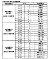
次に、図10を参照して、主制御回路61のROM65に記憶されている内部抽籤テーブル決定テーブルについて説明する。なお、図10は、本実施形態における遊技機1の内部抽籤テーブル決定テーブルの例を示す図である。   Next, an internal lottery table determination table stored in the ROM 65 of the main control circuit 61 will be described with reference to FIG. FIG. 10 is a diagram illustrating an example of an internal lottery table determination table of the gaming machine 1 in the present embodiment.

内部抽籤テーブル決定テーブルには、遊技状態毎に、内部抽籤処理(図48、図49参照)において内部当籤役を決定するために使用する内部抽籤テーブルの種別と、抽籤回数が規定されている。具体的には、内部抽籤テーブル決定テーブルに基づいて、遊技状態が一般遊技状態である場合には、一般遊技状態用内部抽籤テーブルが使用されることが決定され、遊技状態がRT1作動状態である場合には、RT1作動状態用内部抽籤テーブルが使用されることが決定され、遊技状態がRT2作動状態である場合には、RT2作動状態用内部抽籤テーブルが使用されることが決定され、遊技状態がMB1作動状態である場合には、MB1作動状態用内部抽籤テーブルが使用されることが決定され、遊技状態がMB2作動状態である場合には、MB2作動状態用内部抽籤テーブルが使用されることが決定される。   In the internal lottery table determination table, the type of the internal lottery table used for determining the internal winning combination in the internal lottery process (see FIGS. 48 and 49) and the number of lotteries are defined for each gaming state. Specifically, based on the internal lottery table determination table, when the gaming state is the general gaming state, it is determined that the general gaming state internal lottery table is used, and the gaming state is the RT1 operating state. In this case, it is determined that the internal lottery table for the RT1 operating state is used, and when the gaming state is the RT2 operating state, it is determined that the internal lottery table for the RT2 operating state is used, and the gaming state Is determined to use the MB1 operating state internal lottery table, and when the gaming state is the MB2 operating state, the MB2 operating state internal lottery table is used. Is determined.

また、内部抽籤テーブル決定テーブルに基づいて、遊技状態が一般遊技状態である場合には抽籤回数として「10」が決定され、RT1作動状態である場合には抽籤回数として「15」が決定され、遊技状態がRT2作動状態である場合には抽籤回数として「12」が決定され、遊技状態がMB1作動状態である場合には抽籤回数として「6」が決定され、遊技状態がMB2作動状態である場合には抽籤回数として「3」が決定される。   Further, based on the internal lottery table determination table, “10” is determined as the number of lotteries when the gaming state is the general gaming state, and “15” is determined as the number of lotteries when the RT1 is operating. When the gaming state is the RT2 operating state, “12” is determined as the number of lotteries, and when the gaming state is the MB1 operating state, “6” is determined as the number of lotteries, and the gaming state is the MB2 operating state. In this case, “3” is determined as the number of lotteries.

次に、図11〜図15を参照して、主制御回路61のROM65に記憶されている内部抽籤テーブルについて説明する。なお、図11は、本実施形態における遊技機1の一般遊技状態用内部抽籤テーブルの例を示す図である。図12は、本実施形態における遊技機1のRT1作動状態用内部抽籤テーブルの例を示す図である。図13は、本実施形態における遊技機1のRT2作動状態用内部抽籤テーブルの例を示す図である。図14は、本実施形態における遊技機1のMB1作動状態用内部抽籤テーブルの例を示す図である。図15は、本実施形態における遊技機1のMB2作動状態用内部抽籤テーブルの例を示す図である。   Next, an internal lottery table stored in the ROM 65 of the main control circuit 61 will be described with reference to FIGS. FIG. 11 is a diagram showing an example of a general gaming state internal lottery table of the gaming machine 1 in the present embodiment. FIG. 12 is a diagram illustrating an example of the internal lottery table for the RT1 operation state of the gaming machine 1 in the present embodiment. FIG. 13 is a diagram illustrating an example of the internal lottery table for the RT2 operating state of the gaming machine 1 in the present embodiment. FIG. 14 is a diagram showing an example of an internal lottery table for the MB1 operating state of the gaming machine 1 in the present embodiment. FIG. 15 is a diagram illustrating an example of an internal lottery table for the MB2 operating state of the gaming machine 1 in the present embodiment.

内部抽籤テーブルは、後述する内部抽籤処理(図48、図49参照)において、内部当籤役を決定する際に使用するテーブルである。内部抽籤テーブルには当籤番号毎に抽籤値とデータポインタとが規定されている。抽籤値は、データポインタを決定するために用いられる数値である。データポインタは、後述の当たり要求フラグの決定に用いられるデータであり、小役・リプレイ用データポインタ、ボーナス用データポインタとが規定されている。小役・リプレイ用データポインタとしては、「0」〜「14」の数値が規定されており、ボーナス用データポインタとしては「0」〜「1」が規定されている。当たり要求フラグは、一又は複数の役と対応しており、小役・リプレイ用データポインタに応じて一又は複数の役が内部当籤役として決定され、ボーナス用データポインタに応じてMBが内部当籤役として決定される。   The internal lottery table is a table used when determining an internal winning combination in an internal lottery process (see FIGS. 48 and 49) described later. In the internal lottery table, lottery values and data pointers are defined for each winning number. The lottery value is a numerical value used to determine the data pointer. The data pointer is data used to determine a hit request flag, which will be described later, and a small role / replay data pointer and a bonus data pointer are defined. Numeric values “0” to “14” are defined as the small role / replay data pointer, and “0” to “1” are defined as the bonus data pointer. The winning request flag corresponds to one or a plurality of combinations, one or more combinations are determined as internal winning combinations according to the small combination / replay data pointer, and MB is determined as an internal winning combination according to the bonus data pointer. It is decided as a role.

各内部抽籤テーブルは、設定値毎に各当籤番号に対応する抽籤値を規定している。図11〜図15に示す内部抽籤テーブルには、設定値「1」に対応する抽籤値を示し、設定値「4」、「6」、「H」のそれぞれに対応する抽籤値については記載を省略している。   Each internal lottery table defines a lottery value corresponding to each winning number for each set value. In the internal lottery tables shown in FIGS. 11 to 15, the lottery value corresponding to the set value “1” is shown, and the lottery values corresponding to the set values “4”, “6”, and “H” are described. Omitted.

次に、抽籤値を用いてデータポインタを決定する方法、すなわち、内部抽籤の方法について説明する。内部抽籤は、予め定められた数値の範囲「0〜65535」の中から乱数値を抽出し、抽出した乱数値から各当籤番号に対応する抽籤値を順次減算するとともに、桁かりが行われたか否かを判定することにより行われる。桁かりは、減じられる対象の数値の方が小さい場合に行われ、換言すれば減算の結果が負となるときに行われる。例えば、図11の一般遊技状態用内部抽籤テーブルが内部抽籤テーブルに決定された場合において、抽出した乱数値が「400」である場合、初めに、メインCPU64は、「400」から当籤番号「10」対応する抽籤値「350」を減算する。減算結果は「400−350=50」であり、正である。次いで、メインCPU64は、この減算後の値「50」から当籤番号「9」に対応する抽籤値「9000」を減算する。減算結果は「50−9000=−8950」であり、負である。したがって、メインCPU64は、内部当籤役として当籤番号「9」、すなわち、小役・リプレイ用データポインタとして「9」、ボーナス用データポインタとして「0」を決定する。したがって、抽籤値として規定されている数値が大きいほど、対応する当籤番号のデータポインタが決定される可能性が高くなる。また、各当籤番号の当籤確率は、「各当籤番号に対応する抽籤値/抽出される可能性のある全ての乱数値の個数(「65536」)」となる。   Next, a method for determining a data pointer using a lottery value, that is, an internal lottery method will be described. In the internal lottery, a random number value is extracted from a predetermined numerical range “0 to 65535”, and the lottery value corresponding to each winning number is sequentially subtracted from the extracted random number value, and whether a digit is performed. This is done by determining whether or not. Digit is performed when the numerical value to be subtracted is smaller, in other words, when the result of subtraction is negative. For example, in the case where the internal lottery table for the general gaming state in FIG. 11 is determined as the internal lottery table, when the extracted random number value is “400”, first, the main CPU 64 starts with “400” to win the winning number “10”. The corresponding lottery value “350” is subtracted. The subtraction result is “400−350 = 50”, which is positive. Next, the main CPU 64 subtracts the lottery value “9000” corresponding to the winning number “9” from the subtracted value “50”. The subtraction result is “50−9000 = −8950”, which is negative. Therefore, the main CPU 64 determines the winning number “9” as the internal winning combination, that is, “9” as the small combination / replay data pointer and “0” as the bonus data pointer. Therefore, the larger the numerical value defined as the lottery value, the higher the possibility that the data pointer of the corresponding winning number will be determined. Also, the winning probability of each winning number is “the lottery value corresponding to each winning number / the number of all random values that may be extracted (“ 65536 ”)”.

なお、後述する抽籤値を用いて行う各種抽籤は、当該データポインタを決定する場合と同様である。以下、抽籤値による各種抽籤の方法は、内部抽籤の方法と同様であるので説明を省略する。   Note that various types of lottery performed using lottery values, which will be described later, are the same as those for determining the data pointer. Hereinafter, the various lottery methods based on the lottery value are the same as the internal lottery method, and thus description thereof is omitted.

図11に示す一般遊技状態用内部抽籤テーブルには、当籤番号「1」〜当籤番号「10」に応じた抽籤値及びデータポインタが規定されている。一般遊技状態用内部抽籤テーブルは、当籤番号「1」〜当籤番号「9」に対して、小役・リプレイ用データポインタとして「1」〜「9」のうちの何れかの値を規定し、ボーナス用データポインタとしては「0」を規定している。よって、当籤番号「1」〜当籤番号「9」が決定された場合には、複数の小役又はリプレイの中から一の役又は複数の役からなる役群が内部当籤役として決定される。なお、役群が内部当籤役に決定されることは、役群を構成する複数の役が同時に内部当籤役として決定されたことと同義である。   In the internal lottery table for the general gaming state shown in FIG. 11, lottery values and data pointers corresponding to the winning numbers “1” to “10” are defined. The internal lottery table for the general gaming state defines any value from “1” to “9” as a data pointer for small role / replay for the winning numbers “1” to “9”, “0” is defined as the bonus data pointer. Therefore, when the winning numbers “1” to “9” are determined, a combination of one combination or a plurality of combinations is determined as an internal winning combination from a plurality of small combinations or replays. It is to be noted that the determination of the role group as an internal winning combination is synonymous with the fact that a plurality of combinations constituting the role group are simultaneously determined as internal winning combinations.

また、一般遊技状態用内部抽籤テーブルは、当籤番号「10」に対して、小役・リプレイ用データポインタとして「0」の数値を規定し、ボーナス用データポインタとしては「1」の数値を規定していることから、当籤番号「10」が決定された場合には、MBが内部当籤役として決定される。   Also, the internal lottery table for the general gaming state defines a numerical value of “0” as the small role / replay data pointer and a numerical value of “1” as the bonus data pointer for the winning number “10”. Therefore, when the winning number “10” is determined, the MB is determined as the internal winning combination.

図12に示すRT1作動状態用内部抽籤テーブルは、RT1作動状態において使用されるテーブルであり、当籤番号「1」〜当籤番号「15」に応じた抽籤値及びデータポインタが規定されている。RT1作動状態用内部抽籤テーブルは、当籤番号「1」〜当籤番号「14」に対して、小役・リプレイ用データポインタとして「1」〜「14」のうちの何れかの値を規定し、ボーナス用データポインタとしては「0」を規定している。よって、当籤番号「1」〜当籤番号「14」が決定された場合には、複数の小役又はリプレイの中から一の役又は複数の役からなる役群が内部当籤役として決定される。   The internal lottery table for the RT1 operation state shown in FIG. 12 is a table used in the RT1 operation state, and lottery values and data pointers corresponding to the winning numbers “1” to “15” are defined. The RT1 operating state internal lottery table defines any value of “1” to “14” as a small role / replay data pointer for the winning numbers “1” to “14”, “0” is defined as the bonus data pointer. Therefore, when the winning number “1” to the winning number “14” are determined, a combination of one combination or a plurality of combinations from the plurality of small combinations or replays is determined as the internal winning combination.

また、RT1作動状態用内部抽籤テーブルは、当籤番号「15」に対して、小役・リプレイ用データポインタとして「0」の数値を規定し、ボーナス用データポインタとしては「1」の数値を規定していることから、当籤番号「15」が決定された場合には、MBが内部当籤役として決定される。   In the RT1 operating state internal lottery table, for the winning number “15”, a value of “0” is defined as a small role / replay data pointer, and a value of “1” is defined as a bonus data pointer. Therefore, when the winning number “15” is determined, the MB is determined as the internal winning combination.

図13に示すRT2作動状態用内部抽籤テーブルは、RT2作動状態において使用されるテーブルであり、当籤番号「1」〜当籤番号「12」に応じた抽籤値及びデータポインタが規定されている。RT2作動状態用内部抽籤テーブルは、当籤番号「1」〜当籤番号「11」に対して、小役・リプレイ用データポインタとして「1」〜「9」、「13」〜「14」のうちの何れかの値を規定し、ボーナス用データポインタとしては「0」を規定している。よって、当籤番号「1」〜当籤番号「11」が決定された場合には、複数の小役又はリプレイの中から一の役又は複数の役からなる役群が内部当籤役として決定される。   The RT2 operating state internal lottery table shown in FIG. 13 is a table used in the RT2 operating state, and lottery values and data pointers corresponding to the winning numbers “1” to “12” are defined. The internal lottery table for the RT2 operating state includes “1” to “9”, “13” to “14” as data pointers for small roles / replays for the winning numbers “1” to “11”. Any value is defined, and “0” is defined as the bonus data pointer. Therefore, when the winning numbers “1” to “11” are determined, a combination of one combination or a plurality of combinations is determined as an internal winning combination from a plurality of small combinations or replays.

また、RT2作動状態用内部抽籤テーブルは、当籤番号「12」に対して、小役・リプレイ用データポインタとして「0」の数値を規定し、ボーナス用データポインタとしては「1」の数値を規定していることから、当籤番号「12」が決定された場合には、MBが内部当籤役として決定される。   In the RT2 operating state internal lottery table, for the winning number “12”, a numerical value “0” is defined as a small role / replay data pointer, and a numerical value “1” is defined as a bonus data pointer. Therefore, when the winning number “12” is determined, the MB is determined as the internal winning combination.

なお、RT2作動状態用内部抽籤テーブルには、当籤番号「9」に対応する抽籤値が「45000」に規定されている。一方、一般遊技状態用内部抽籤テーブルにおいては、当籤番号「9」に対応する抽籤値が「9000」に規定されており、RT1作動状態用内部抽籤テーブルには、当籤番号「9」に対応する抽籤値が「8300」に規定されている。後述するように一般遊技状態用内部抽籤テーブル、RT1作動状態用内部抽籤テーブル、RT2作動状態用内部抽籤テーブルにおいて、当籤番号「9」に対応するデータポインタは通常リプレイに対応していることから、RT1作動状態においては、一般遊技状態、及びRT1作動状態と比較して通常リプレイの当籤確率が「9000/65536(約13.7%)」、「8300/65536(約12.7%)から「45000/65536(約68.7%)」に上がることとなる。したがって、RT2作動状態においては、一般遊技状態、及びRT1作動状態と比較して、内部抽籤に外れる確率が低下するとともに通常リプレイが内部当籤役に決定される確率が増加することから、メダルの減少率を抑制させることができる。   In the RT2 operating state internal lottery table, the lottery value corresponding to the winning number “9” is defined as “45000”. On the other hand, in the internal lottery table for the general gaming state, the lottery value corresponding to the winning number “9” is defined as “9000”, and the internal lottery table for the RT1 operating state corresponds to the winning number “9”. The lottery value is defined as “8300”. As will be described later, in the internal lottery table for the general gaming state, the internal lottery table for the RT1 operation state, and the internal lottery table for the RT2 operation state, the data pointer corresponding to the winning number “9” corresponds to the normal replay. In the RT1 operating state, the winning probability of the normal replay is “9000/65536 (about 13.7%)”, “8300/65536 (about 12.7%) compared to the general gaming state and the RT1 operating state” 45000/65536 (about 68.7%) ". Therefore, in the RT2 operating state, compared to the general gaming state and the RT1 operating state, the probability of losing the internal lottery decreases and the probability that the normal replay is determined to be an internal winning combination increases. The rate can be suppressed.

図14に示すMB1作動状態用内部抽籤テーブルは、遊技状態がRT1作動状態であって、後述するMB作動役が成立した場合に使用されるテーブルであり、当籤番号「1」〜「6」に応じた抽籤値及びデータポインタが規定されており、各当籤番号に規定された抽籤値は、RT1作動状態用内部抽籤テーブルの当籤番号「9」〜「14」とそれぞれ対応し、それぞれの当籤番号に対する抽籤値は、RT1作動状態用内部抽籤テーブルに規定された抽籤値と同一である。   The MB1 operating state internal lottery table shown in FIG. 14 is a table used when the gaming state is the RT1 operating state and the MB operating combination described later is established, and the winning numbers “1” to “6” are assigned. The lottery values and data pointers corresponding thereto are defined, and the lottery values defined for each winning number correspond to the winning numbers “9” to “14” in the RT1 operating state internal lottery table, respectively. The lottery value with respect to is the same as the lottery value defined in the internal lottery table for the RT1 operation state.

図15に示すMB2作動状態用内部抽籤テーブルは、遊技状態がRT2作動状態であって、後述するMB作動役が成立した場合に使用されるテーブルであり、当籤番号「1」〜「3」に応じた抽籤値及びデータポインタが規定されており、各当籤番号に規定された抽籤値は、RT2作動状態用内部抽籤テーブルの当籤番号「9」〜「11」とそれぞれ対応し、それぞれの当籤番号に対する抽籤値は、RT2作動状態用内部抽籤テーブルに規定された抽籤値と同一である。   The MB2 operating state internal lottery table shown in FIG. 15 is a table used when the gaming state is the RT2 operating state and the MB operating combination described later is established, and the winning numbers “1” to “3” are assigned. The lottery values and data pointers corresponding thereto are defined, and the lottery values defined for each winning number correspond to the winning numbers “9” to “11” of the internal lottery table for the RT2 operating state, respectively, The lottery value with respect to is the same as the lottery value defined in the internal lottery table for the RT2 operating state.

上述の内部抽籤で抽出された乱数値は、図50を用いて後述するロック抽籤においても用いられ、抽出された乱数値から、後述のロック抽籤テーブルに基づいて開始時ロック情報、及び終了時ロック情報が決定される。図11〜図13の右欄に内部抽籤により当籤番号が決定されたときに決定されるロック情報を示す。図11に示す一般遊技状態においては、全ての当籤番号に対して、開始時ロック情報、及び終了時ロック情報は「0」であることから、一般遊技状態では、内部当籤役として何れの当籤番号が決定された場合であっても、開始時ロック情報、及び終了時ロック情報は共に「0」が決定されることとなる。一方、RT1作動状態、RT2作動状態においては、当籤番号に対し、開始時ロック情報は「0」〜「3」のいずれかが、終了時ロック情報は「0」〜「5」のいずれかが決定される。例えば、RT1作動状態において、内部当籤役として当籤番号「9」、すなわち小役・リプレイ用データポインタとして「9」(通常リプレイ)が決定された場合には、開始時ロック情報として「0」、終了時ロック情報として「0」〜「3」のいずれかが決定されることとなる。開始時ロック情報は後述する開始時ロック時間を決定するために基となる情報であり、終了時ロック情報は後述する終了時ロック時間を決定するために基となる情報である。   The random number value extracted by the above-mentioned internal lottery is also used in the lock lottery described later with reference to FIG. 50. From the extracted random number value, the start-time lock information and the end-time lock are based on the lock lottery table described later. Information is determined. Lock information determined when a winning number is determined by internal lottery is shown in the right column of FIGS. In the general gaming state shown in FIG. 11, since the lock information at the start time and the lock information at the end time are “0” for all the winning numbers, any winning number as an internal winning combination in the general gaming state. Is determined, both the start-time lock information and the end-time lock information are determined to be “0”. On the other hand, in the RT1 operation state and the RT2 operation state, the start lock information is any of “0” to “3” and the end lock information is any of “0” to “5” with respect to the winning number. It is determined. For example, in the RT1 operation state, when the winning number “9” is determined as the internal winning combination, that is, “9” (normal replay) is determined as the small role / replay data pointer, One of “0” to “3” is determined as the lock information at the end. The start-time lock information is information used to determine a start-time lock time, which will be described later, and the end-time lock information is information used to determine an end-time lock time, which will be described later.

なお、本実施形態において各内部抽籤テーブルは、当籤番号(データポインタ)に対応する抽籤値を規定しているが、抽籤値は、乱数値が抽出される範囲である「0〜65535」に対する割合である。したがって、抽籤値に代えて、当籤番号(データポインタ)毎に対応する乱数幅(例えば、「0〜654」)を当籤範囲として規定することもできる。具体的には、乱数値が何れの当籤番号(データポインタ)に対応する当籤範囲に含まれるかを判定することにより、内部当籤役を決定することができる。すなわち、各内部抽籤テーブルが抽籤値を規定することは、役又は役群毎の乱数幅(当籤範囲)を規定することと同義である。   In this embodiment, each internal lottery table defines a lottery value corresponding to a winning number (data pointer), but the lottery value is a ratio with respect to “0 to 65535” that is a range in which random number values are extracted. It is. Therefore, instead of the lottery value, a random number width (for example, “0 to 654”) corresponding to each winning number (data pointer) can be defined as the winning range. Specifically, the internal winning combination can be determined by determining which winning number (data pointer) corresponds to the winning range corresponding to the random number value. That is, defining each lottery value by each internal lottery table is synonymous with defining a random number width (winning range) for each combination or combination.

次に、図16及び図17を参照して、主制御回路61のROM65に記憶されているRT1作動状態用ロック抽籤テーブル、RT2作動状態用ロック抽籤テーブルについて説明する。なお、図16は、本実施形態における遊技機1のRT1作動状態用ロック抽籤テーブルの例を示す図である。図17は、本実施形態における遊技機1のRT2作動状態用ロック抽籤テーブルの例を示す図である。   Next, the RT1 operation state lock lottery table and the RT2 operation state lock lottery table stored in the ROM 65 of the main control circuit 61 will be described with reference to FIGS. 16 and 17. FIG. 16 is a diagram illustrating an example of the RT1 operating state lock lottery table of the gaming machine 1 in the present embodiment. FIG. 17 is a diagram showing an example of the RT2 operating state lock lottery table of the gaming machine 1 in the present embodiment.

RT1作動状態用ロック抽籤テーブル、RT2作動状態用ロック抽籤テーブルは、後述するロック抽籤処理(図50参照)において、開始時ロック情報、及び終了時ロック情報を決定する際に使用するテーブルである。RT1作動状態用ロック抽籤テーブル、RT2作動状態用ロック抽籤テーブルには、ロック番号毎に抽籤値と開始時ロック情報、及び終了時ロック情報とが規定されている。抽籤値は開始時ロック情報、及び終了時ロック情報を決定するために用いられる数値である。開始時ロック情報、及び終了時ロック情報は、後述のロックカウンタに格納される数値を決定する際に用いられるデータであり、開始時ロック情報としては「0」〜「3」の数値が規定されており、終了時ロック情報としては「0」〜「5」の数値が規定されている。なお、抽籤値を用いて開始時ロック情報、及び終了時ロック情報を決定する方法は、上述の内部抽籤方法と同様であり、内部抽籤において抽出された乱数値が用いられる。   The RT1 operation state lock lottery table and the RT2 operation state lock lottery table are tables used when determining start-time lock information and end-time lock information in a lock lottery process (see FIG. 50) described later. In the RT1 operation state lock lottery table and the RT2 operation state lock lottery table, a lottery value, start lock information, and end lock information are defined for each lock number. The lottery value is a numerical value used for determining the start lock information and the end lock information. The start-time lock information and the end-time lock information are data used when determining numerical values stored in a lock counter, which will be described later, and numerical values from “0” to “3” are defined as the start-time lock information. As the end-time lock information, numerical values “0” to “5” are defined. Note that the method of determining the start time lock information and the end time lock information using the lottery value is the same as the above-described internal lottery method, and the random value extracted in the internal lottery is used.

図16に示すRT1作動状態用ロック抽籤テーブルには、ロック番号「1」〜ロック番号「12」に応じた抽籤値、開始時ロック情報、及び終了時ロック情報が規定されている。ロック番号「1」に対する抽籤値は、RT1作動状態用内部抽籤テーブルの当籤番号「1」〜「8」に規定されたそれぞれの抽籤値の合算値と等しく、開始時ロック情報、及び終了時ロック情報として共に「0」が規定されている。従って、内部抽籤により当籤番号「1」〜「8」、すなわち小役・リプレイ用データポインタとして「1」〜「8」が決定された場合には、開始時ロック情報、及び終了時ロック情報として共に「0」が決定される。また、ロック番号「2」〜「5」に対する抽籤値の合算値は、RT1作動状態用内部抽籤テーブルの当籤番号「9」の抽籤値と等しく、開始時ロック情報として「0」、終了時ロック情報として「0」〜「3」が規定されている。従って、内部抽籤により当籤番号「9」、すなわち小役・リプレイ用データポインタとして「9」(通常リプレイ)が決定された場合には、開始時ロック情報として「0」、終了時ロック情報として「0」〜「3」のいずれかが決定される。また、ロック番号「6」に対する抽籤値は、RT1作動状態用内部抽籤テーブルの当籤番号「10」〜「12」に規定されたそれぞれの抽籤値の合算値と等しく、開始時ロック情報として「1」、終了時ロック情報として「4」が規定されている。従って内部抽籤により当籤番号「10」〜「12」、すなわち小役・リプレイ用データポインタとして「10」(後述の、三択リプレイ役群L)、「11」(後述の、三択リプレイ役群C)、「12」(後述の、三択リプレイ役群R)が決定された場合には、開始時ロック情報として「1」、終了時ロック情報として「4」が決定される。また、ロック番号「7」〜「10」に対する抽籤値の合算値は、RT1作動状態用内部抽籤テーブルの当籤番号「13」の抽籤値と等しく、開始時ロック情報として「0」、終了時ロック情報として「0」〜「3」が規定されている。従って、内部抽籤により当籤番号「13」、すなわち小役・リプレイ用データポインタとして「13」(後述の、特殊リプレイ2)が決定された場合には、開始時ロック情報として「0」、終了時ロック情報として「0」〜「3」のいずれかが決定される。また、ロック番号「11」に対する抽籤値は、RT1作動状態用内部抽籤テーブルの当籤番号「14」の抽籤値と等しく、開始時ロック情報として「2」、終了時ロック情報として「5」が規定されている。従って、内部抽籤により当籤番号「14」、すなわち小役・リプレイ用データポインタとして「14」(後述の、特殊リプレイ役群)が決定された場合には、開始時ロック情報として「2」、終了時ロック情報として「5」が決定される。また、ロック番号「12」に対する抽籤値は、RT1作動状態用内部抽籤テーブルの当籤番号「15」に規定された抽籤値と等しく、開始時ロック情報、終了時ロック情報として共に「0」が規定されている。従って、内部抽籤により当籤番号「15」、すなわち小役・リプレイ用データポインタとして「15」(後述の、MB)が決定された場合には、開始時ロック情報、終了時ロック情報として共に「0」が決定される。   In the RT1 operating state lock lottery table shown in FIG. 16, lottery values, start-time lock information, and end-time lock information corresponding to the lock numbers “1” to “12” are defined. The lottery value for the lock number “1” is equal to the sum of the lottery values defined in the winning numbers “1” to “8” of the internal lottery table for the RT1 operating state, and the lock information at the start and the lock at the end “0” is defined for both information. Therefore, when the winning numbers “1” to “8”, that is, “1” to “8” are determined as the small role / replay data pointers by the internal lottery, the start lock information and the end lock information are determined. In both cases, “0” is determined. Also, the sum of the lottery values for the lock numbers “2” to “5” is equal to the lottery value of the winning number “9” in the RT1 operation state internal lottery table, “0” as the start lock information, and lock at the end “0” to “3” are defined as information. Therefore, when the winning number “9”, that is, “9” (normal replay) is determined as the small role / replay data pointer by the internal lottery, “0” is set as the start lock information, and “9” is set as the end lock information. Any one of “0” to “3” is determined. Also, the lottery value for the lock number “6” is equal to the sum of the lottery values defined in the winning numbers “10” to “12” of the internal lottery table for the RT1 operating state, and “1” is set as the start lock information. “4” is defined as the lock information at the end. Accordingly, the winning numbers “10” to “12” by internal lottery, that is, “10” (three-choice replay role group L described later) and “11” (three-choice replay role group described later) as data pointers for small roles and replays. C) When “12” (three-choice replay role group R described later) is determined, “1” is determined as the start lock information and “4” is determined as the end lock information. Also, the sum of the lottery values for the lock numbers “7” to “10” is equal to the lottery value of the winning number “13” of the RT1 operating state internal lottery table, “0” as the start lock information, and lock at the end “0” to “3” are defined as information. Therefore, when the winning number “13”, that is, “13” (special replay 2 described later) is determined as the small role / replay data pointer by the internal lottery, “0” is set as the start lock information, and the end time is set. Any one of “0” to “3” is determined as the lock information. In addition, the lottery value for the lock number “11” is equal to the lottery value of the winning number “14” in the internal lottery table for RT1 operation state, and “2” is defined as the lock information at the start and “5” is defined as the lock information at the end. Has been. Therefore, when the winning number “14”, that is, “14” (special replay role group described later) is determined by the internal lottery, that is, “2” as the start lock information, the end “5” is determined as the hour lock information. The lottery value for the lock number “12” is equal to the lottery value defined for the winning number “15” of the internal lottery table for RT1 operation state, and “0” is defined as both the start lock information and the end lock information. Has been. Therefore, when the winning number “15”, that is, “15” (MB, described later) is determined as the small role / replay data pointer by internal lottery, both “0” as the lock information at the start and “0” as the lock information at the end. Is determined.

図17に示すRT2作動状態用ロック抽籤テーブルには、ロック番号「1」〜ロック番号「11」に応じた抽籤値、開始時ロック情報、及び終了時ロック情報が規定されている。ロック番号「1」に対する抽籤値は、RT2作動状態用内部抽籤テーブルの当籤番号「1」〜「8」に規定されたそれぞれの抽籤値の合算値と等しく、開始時ロック情報、及び終了時ロック情報として共に「0」が規定されている。従って、内部抽籤により当籤番号「1」〜「8」、すなわち小役・リプレイ用データポインタとして「1」〜「8」が決定された場合には、開始時ロック情報、及び終了時ロック情報として共に「0」が決定される。また、ロック番号「2」〜「5」に対する抽籤値の合算値は、RT2作動状態用内部抽籤テーブルの当籤番号「9」の抽籤値と等しく、開始時ロック情報として「0」、終了時ロック情報として「0」〜「3」が規定されている。従って、内部抽籤により当籤番号「9」、すなわち小役・リプレイ用データポインタとして「9」(通常リプレイ)が決定された場合には、開始時ロック情報として「0」、終了時ロック情報として「0」〜「3」のいずれかが決定される。また、ロック番号「6」〜「9」に対する抽籤値の合算値は、RT2作動状態用内部抽籤テーブルの当籤番号「10」の抽籤値と等しく、開始時ロック情報として「0」、終了時ロック情報として「0」〜「3」が規定されている。従って、内部抽籤により当籤番号「10」、すなわち小役・リプレイ用データポインタとして「13」(特殊リプレイ2)が決定された場合には、開始時ロック情報として「0」、終了時ロック情報として「0」〜「3」のいずれかが決定される。また、ロック番号「10」に対する抽籤値は、RT2作動状態用内部抽籤テーブルの当籤番号「11」に規定された抽籤値と等しく、開始時ロック情報として「2」、終了時ロック情報として「5」が規定されている。従って内部抽籤により当籤番号「11」、すなわち小役・リプレイ用データポインタとして「14」(特殊リプレイ役群)が決定された場合には、開始時ロック情報として「2」、終了時ロック情報として「5」が決定される。また、ロック番号「11」に対する抽籤値は、RT2作動状態用内部抽籤テーブルの当籤番号「12」の抽籤値と等しく、開始時ロック情報として「3」、終了時ロック情報として「0」が規定されている。従って、内部抽籤により当籤番号「12」、すなわちボーナス用データポインタとして「1」(MB)が決定された場合には、開始時ロック情報として「3」、終了時ロック情報として「0」が決定される。   In the RT2 operating state lock lottery table shown in FIG. 17, lottery values, start-time lock information, and end-time lock information corresponding to the lock numbers “1” to “11” are defined. The lottery value for the lock number “1” is equal to the sum of the lottery values defined in the winning numbers “1” to “8” of the RT2 operating state internal lottery table, and the start-time lock information and the end-time lock “0” is defined for both information. Therefore, when the winning numbers “1” to “8”, that is, “1” to “8” are determined as the small role / replay data pointers by the internal lottery, the start lock information and the end lock information are determined. In both cases, “0” is determined. Also, the sum of the lottery values for the lock numbers “2” to “5” is equal to the lottery value of the winning number “9” in the RT2 operating state internal lottery table. “0” to “3” are defined as information. Therefore, when the winning number “9”, that is, “9” (normal replay) is determined as the small role / replay data pointer by the internal lottery, “0” is set as the start lock information, and “9” is set as the end lock information. Any one of “0” to “3” is determined. The sum of lottery values for the lock numbers “6” to “9” is equal to the lottery value of the winning number “10” in the RT2 operating state internal lottery table, “0” as the start lock information, and lock at the end. “0” to “3” are defined as information. Therefore, when the winning number “10”, that is, “13” (special replay 2) is determined as the small role / replay data pointer by the internal lottery, “0” is set as the start lock information, and the end lock information is set as the end lock information. Any one of “0” to “3” is determined. The lottery value for the lock number “10” is equal to the lottery value defined for the winning number “11” in the RT2 operating state internal lottery table, “2” as the start lock information, and “5” as the end lock information. Is defined. Accordingly, when the winning number “11”, that is, “14” (special replay role group) is determined as the data pointer for the small role / replay by the internal lottery, “2” as the start lock information and as the lock information at the end “5” is determined. The lottery value for the lock number “11” is equal to the lottery value of the winning number “12” in the RT2 operating state internal lottery table, and “3” is specified as the start lock information and “0” is specified as the end lock information. Has been. Therefore, when the winning number “12”, that is, “1” (MB) as the bonus data pointer is determined by internal lottery, “3” is determined as the start lock information and “0” is determined as the end lock information. Is done.

次に、図18を参照して、主制御回路61のROM65に記憶されているロックカウンタ決定テーブルについて説明する。なお、図18は、本実施形態における遊技機1のロックカウンタ決定テーブルの例を示す図である。   Next, a lock counter determination table stored in the ROM 65 of the main control circuit 61 will be described with reference to FIG. FIG. 18 is a diagram illustrating an example of the lock counter determination table of the gaming machine 1 in the present embodiment.

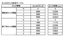
図18に示すロックカウンタ決定テーブルは、ロックカウンタにセットする値を決定するために用いられるテーブルであり、ロック抽籤処理においてロック抽籤テーブルに基づいて決定された開始時ロック情報、及び終了時ロック情報に応じた値が規定されている。具体的には、開始時ロック情報が「0」である場合にはロックカウンタに「0」がセットされ、開始時ロック情報が「1」である場合にはロックカウンタに「2000」がセットされ、開始時ロック情報が「2」である場合にはロックカウンタに「3000」がセットされ、開始時ロック情報が「3」である場合にはロックカウンタに「9000」がセットされる。また、終了時ロック情報が「0」である場合にはロックカウンタに「0」がセットされ、終了時ロック情報が「1」である場合にはロックカウンタに「1000」がセットされ、終了時ロック情報が「2」である場合にはロックカウンタに「2000」がセットされ、終了時ロック情報が「3」である場合にはロックカウンタに「3000」がセットされ、終了時ロック情報が「4」である場合にはロックカウンタに「4000」がセットされ、終了時ロック情報が「5」である場合にはロックカウンタに「5000」がセットされる。ロックカウンタにセットされた値は、後述の1.1173msごとに起動されるメインCPUの制御による割込処理において、「1」ずつ減算され、ロックカウンタの値が「0」になるまで、リールの回転、メダルの受付等がロックされる。例えば、開始時ロック情報が「2」である場合には、ロックカウンタに「2000」がセットされ、ロックカウンタにセットされた値「2000」に1.1173msを乗じた2.2346sが経過するまでロック制御が行われ、ロック制御中には副制御回路62において各種演出が実行される。なお、参考として図18の右欄にロックカウンタの値に対するロック時間を示す。   
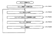
The lock counter determination table shown in FIG. 18 is a table used to determine a value to be set in the lock counter. The start lock information and the end lock information determined based on the lock lottery table in the lock lottery process. A value corresponding to is specified. Specifically, when the lock information at the start is “0”, “0” is set in the lock counter, and when the lock information at the start is “1”, “2000” is set in the lock counter. When the start lock information is “2”, “3000” is set in the lock counter, and when the start lock information is “3”, “9000” is set in the lock counter. When the lock information at the end is “0”, “0” is set in the lock counter. When the lock information at the end is “1”, “1000” is set in the lock counter. When the lock information is “2”, “2000” is set to the lock counter, and when the lock information at the end is “3”, “3000” is set to the lock counter. If it is “4”, “4000” is set in the lock counter, and if the lock information at the end is “5”, “5000” is set in the lock counter. The value set in the lock counter is decremented by “1” by an interruption process under the control of the main CPU activated every 1.1173 ms, which will be described later, until the value of the lock counter becomes “0”. Rotation, medal reception, etc. are locked. For example, when the start lock information is “2”, “2000” is set in the lock counter, and 2.2346 s obtained by multiplying the value “2000” set in the lock counter by 1.1173 ms elapses. Lock control is performed, and various effects are executed in the sub-control circuit 62 during the lock control. For reference, the right column of FIG. 18 shows the lock time with respect to the value of the lock counter.

ここで、開始時ロック情報に基づいて決定されるロック時間を開始時ロック時間という。開始時ロック時間は、開始時ロック制御が行われる時間のことである。開始時ロック制御は、開始操作に基づいて内部当籤役が決定されてから開始時ロック時間が経過するまでの間、全ての停止操作の検出を無効とする制御であり、メインCPU64により制御される。一方、終了時ロック情報に基づいて決定されるロック時間を終了時ロック時間という。終了時ロック時間は、終了時ロック制御が行われる時間のことである。終了時ロック制御は、表示役が決定されてから終了時ロック時間が経過するまでの間、開始操作の検出を無効とする制御であり、メインCPU64により制御される。   Here, the lock time determined based on the start time lock information is referred to as the start time lock time. The start lock time is a time during which the start lock control is performed. The start-time lock control is a control for invalidating detection of all stop operations until the start-time lock time elapses after the internal winning combination is determined based on the start operation, and is controlled by the main CPU 64. . On the other hand, the lock time determined based on the end-time lock information is referred to as the end-time lock time. The end lock time is a time during which the end lock control is performed. The end-time lock control is a control for invalidating the detection of the start operation until the end-time lock time elapses after the display combination is determined, and is controlled by the main CPU 64.

次に、図19を参照して、遊技機1における遊技状態・作動状態の移行について説明する。なお、図19は、本実施形態における遊技機1の遊技状態・作動状態の移行の例を示すである。主制御回路61において制御される遊技機1の遊技状態には、一般遊技状態がある。また、主制御回路61において制御される遊技機1の作動状態には、RT1作動状態、RT2作動状態、MB作動状態がある。これらの各種遊技状態・作動状態は、基本的に、内部当籤役として決定される可能性のある役の種類や、内部当籤役の当籤確率、成立した役の種類などにより区別される。   Next, with reference to FIG. 19, the transition of the gaming state / operating state in the gaming machine 1 will be described. FIG. 19 shows an example of the transition of the gaming state / operating state of the gaming machine 1 in this embodiment. The gaming state of the gaming machine 1 controlled by the main control circuit 61 includes a general gaming state. The operating state of the gaming machine 1 controlled by the main control circuit 61 includes an RT1 operating state, an RT2 operating state, and an MB operating state. These various game states / actuation states are basically distinguished according to the type of winning combination that may be determined as an internal winning combination, the winning probability of the internal winning combination, the type of established winning combination, and the like.

まず、一般遊技状態への移行について説明する。一般遊技状態へは、メインCPU64により設定値の更新がされたことに基づいてRAMクリアが行われた場合、またはエラー検出がされたことに基づいてRAMクリアが行われた場合に移行が行われ、これ以外の条件で一般遊技状態へ移行することはない。   First, the transition to the general gaming state will be described. When the RAM clear is performed based on the setting value being updated by the main CPU 64 or the RAM clear is performed based on the error detection, the transition to the general gaming state is performed. In other conditions, the game does not enter the general gaming state.

次に、一般遊技状態からRT1作動状態への移行について説明する。一般遊技状態において、青リンゴ図柄−青リンゴ図柄−青リンゴ図柄(以下、転落役1という)、または、青リンゴ図柄−青リンゴ図柄−ベル図柄(以下、転落役2という)が成立することによりRT1作動状態へ移行する。後述するように、転落役1、転落役2は、正解役1及び/または正解役2と同時に内部当籤する役であり、これらの役が重複当籤した場合には、遊技者による第1停止操作が行われたリール(左リール、中リール、右リール)の種別に基づいて、転落役1、転落役2、正解役1または正解役2のいずれかの役が成立する。従って、転落役1又は転落役2が成立せずに正解役1又は正解役2が成立し続けた場合には、一般遊技状態からRT1作動状態への移行が行われないが、転落役1又は転落役2が成立した場合にはRT1作動状態への移行が行われる。以下、転落役1、転落役2を総称して、転落役といい、正解役1、正解役2を総称して正解役という。   Next, the transition from the general gaming state to the RT1 operating state will be described. In the general gaming state, when the green apple symbol-green apple symbol-green apple symbol (hereinafter referred to as the falling role 1) or green apple symbol-green apple symbol-bell symbol (hereinafter referred to as the falling symbol 2) is established. Transition to the RT1 operating state. As will be described later, the falling combination 1 and the falling combination 2 are internal winning combinations at the same time as the correct combination 1 and / or the correct combination 2, and when these combinations are duplicated, the first stop operation by the player Based on the type of the reel (left reel, middle reel, right reel) on which the winning combination is performed, one of the falling combination 1, falling combination 2, correct combination 1 or correct combination 2 is established. Therefore, if the correct combination 1 or correct combination 2 continues to be established without the falling combination 1 or the falling combination 2, the transition from the general gaming state to the RT1 operating state is not performed, but the falling combination 1 or When the falling combination 2 is established, the transition to the RT1 operation state is performed. Hereinafter, the falling combination 1 and the falling combination 2 are collectively referred to as a falling combination, and the correct combination 1 and the correct combination 2 are collectively referred to as a correct combination.

転落役1、転落役2が成立したときのメダルの払出枚数は正解役1、正解役2に対して少ない。しかしながら、RT1作動状態においては、後述するようにリプレイが内部当籤する確率が相対的に高いRT2作動状態への移行抽籤が行なわれることから、遊技者はメダルの払出枚数が少ない転落役1、又は転落役2が表示された場合であっても遊技に対する興趣が失われることはない。   The number of medals to be paid out when the falling combination 1 and the falling combination 2 are established is smaller than the correct combination 1 and the correct combination 2. However, in the RT1 operation state, as described later, since the lottery for the transition to the RT2 operation state with a relatively high probability that the replay is internally won is performed, the player can make the falling combination 1 with a small number of medals paid out, or Even if the falling combination 2 is displayed, the interest in the game is not lost.

次に、RT1作動状態からRT2作動状態への移行について説明する。RT1作動状態において、リプレイ図柄−リプレイ図柄−リプレイ図柄(以下、特殊リプレイ1という)、または、リプレイ図柄−青リンゴ図柄−リプレイ図柄(以下、特殊リプレイ2という)が成立することによりRT2作動状態へ移行する。後述するように、特殊リプレイ1、特殊リプレイ2は、通常リプレイと同時に内部当籤する役であり、これらの役が重複当籤した場合には、遊技者による第1停止操作が行われたリール(左リール、中リール、右リール)の種別に基づいて、特殊リプレイ1、特殊リプレイ2、または通常リプレイのいずれかの役が成立する。また、特殊リプレイ1、特殊リプレイ2の抽籤はRT1作動状態においてのみ行なわれる。以下、特殊リプレイ1、特殊リプレイ2を総称して、特殊リプレイという。   Next, the transition from the RT1 operating state to the RT2 operating state will be described. In the RT1 operating state, when the replay symbol-replay symbol-replay symbol (hereinafter referred to as special replay 1) or replay symbol-green apple symbol-replay symbol (hereinafter referred to as special replay 2) is established, the RT2 operating state is reached. Transition. As will be described later, special replay 1 and special replay 2 are internal winning combinations at the same time as normal replaying. If these winning combinations are duplicated, the reel (left One of special replay 1, special replay 2, and normal replay is established based on the type of reel, middle reel, and right reel). Also, lottery of special replay 1 and special replay 2 is performed only in the RT1 operating state. Hereinafter, special replay 1 and special replay 2 are collectively referred to as special replay.

次に、RT2作動状態からRT1作動状態への移行について説明する。RT2作動状態において転落役1、転落役2が成立することによりRT1作動状態へ移行する。上述のようにRT2作動状態は通常リプレイが内部当籤する確率が高いことから、遊技者は、RT1作動状態において特殊リプレイ1、又は特殊リプレイ2を成立させることでRT2作動状態へ移行させたのちは、RT2作動状態においては転落役1、又は転落役2を成立させないように遊技を行うことで、有利に遊技を行うことができる。   Next, the transition from the RT2 operating state to the RT1 operating state will be described. When the falling combination 1 and the falling combination 2 are established in the RT2 operating state, the state shifts to the RT1 operating state. As described above, in the RT2 operating state, there is a high probability that the normal replay will be internally won. Therefore, after the player transitions to the RT2 operating state by establishing the special replay 1 or the special replay 2 in the RT1 operating state, In the RT2 operating state, the game can be advantageously performed by playing the game so that the falling combination 1 or the falling combination 2 is not established.

次に、副制御回路62における各種遊技状態の移行について説明する。副制御回路62では、主制御回路61において制御される遊技状態とは別に、遊技状態を制御する。副制御回路62において制御する遊技状態(サブ)には、RT1作動状態(サブ)、RT2作動状態(サブ)、AT低確率状態、AT高確率状態、及びAT遊技状態あり、RT1作動状態(サブ)、AT低確率状態、AT高確率状態は、主制御回路61で制御されているRT1作動状態中において副制御回路62で制御される遊技状態であり、RT2作動状態(サブ)、AT遊技状態は、主制御回路61で制御されているRT2作動状態中において副制御回路62で制御される遊技状態である。   Next, the transition of various game states in the sub control circuit 62 will be described. The sub control circuit 62 controls the gaming state separately from the gaming state controlled by the main control circuit 61. The gaming state (sub) controlled by the sub-control circuit 62 includes RT1 operating state (sub), RT2 operating state (sub), AT low probability state, AT high probability state, and AT gaming state, and RT1 operating state (sub). ), The AT low probability state and the AT high probability state are gaming states controlled by the sub-control circuit 62 during the RT1 operating state controlled by the main control circuit 61, the RT2 operating state (sub), and the AT gaming state. Is a gaming state controlled by the sub-control circuit 62 during the RT2 operation state controlled by the main control circuit 61.

AT低確率状態において、ベル図柄−リプレイ図柄−ベル図柄(以下、チャンス役という)、または赤リンゴ図柄−リプレイ図柄−赤リンゴ図柄(以下、MBという)が成立することにより、図71、図72を用いて後述する表示コマンド受信時処理においてAT高確率遊技数決定処理が行われ、AT高確率遊技数として「1」以上が決定された場合にはAT高確率状態へ移行する。また、AT高確率状態において、後述の高確率遊技数カウンタの値が「0」となったことに基づいてAT低確率状態へと移行する。   71, 72 when the bell symbol-replay symbol-bell symbol (hereinafter referred to as a chance role) or red apple symbol-replay symbol-red apple symbol (hereinafter referred to as MB) is established in the AT low probability state. Is used to perform the AT high probability game number determination process in the display command reception process described later, and when “1” or more is determined as the AT high probability game number, the process shifts to the AT high probability state. Further, in the AT high probability state, the state shifts to the AT low probability state based on the fact that the value of the high probability game number counter described later becomes “0”.

次に、図20、図21を参照して、主制御回路61のROM65に記憶されている小役・リプレイ用内部当籤役決定テーブル及びボーナス用内部当籤役決定テーブルについて説明する。なお、図20は、本実施形態における遊技機1の小役・リプレイ用内部当籤役決定テーブルの例を示す図である。図21は、本実施形態における遊技機1のボーナス用内部当籤役決定テーブルの例を示す図である。以下、小役・リプレイ用内部当籤役決定テーブル及びボーナス用内部当籤役決定テーブルを総称して、内部当籤役決定テーブルという。   Next, with reference to FIG. 20 and FIG. 21, the small winning combination / replay internal winning combination determining table and bonus internal winning combination determining table stored in the ROM 65 of the main control circuit 61 will be described. FIG. 20 is a diagram illustrating an example of an internal winning combination determination table for a small combination / replay of the gaming machine 1 in the present embodiment. FIG. 21 is a diagram showing an example of a bonus internal winning combination determination table for the gaming machine 1 in the present embodiment. Hereinafter, the small winning combination / replay internal winning combination determining table and the bonus internal winning combination determining table are collectively referred to as an internal winning combination determining table.

内部当籤役決定テーブルは、後述する内部抽籤処理(図48、図49参照)において、データポインタに基づいて内部当籤役を決定する際に使用するテーブルである。内部当籤役決定テーブルには、データポインタに対応する当たり要求フラグが規定されている。当たり要求フラグは、内部当籤役を識別するためのデータである。具体的には、各役が当該データの各ビットと対応しており、何れの役が内部当籤役であるかを、何れのビットが「1」であるか否かによって識別することができる。また、当たり要求フラグは、後述の夫々1バイトからなる内部当籤役1格納領域、内部当籤役2格納領域、又は内部当籤役3格納領域(内部当籤役1格納領域、内部当籤役2格納領域、及び内部当籤役3格納領域をまとめて内部当籤役格納領域という)の何れかに格納されるデータである。   The internal winning combination determination table is a table used when determining an internal winning combination based on a data pointer in an internal lottery process (see FIGS. 48 and 49) described later. In the internal winning combination determination table, a hit request flag corresponding to the data pointer is defined. The winning request flag is data for identifying an internal winning combination. Specifically, each combination corresponds to each bit of the data, and which combination is an internal winning combination can be identified based on which bit is “1”. The winning request flag includes an internal symbol combination 1 storage area, an internal symbol combination 2 storage area, or an internal symbol combination 3 storage area (an internal symbol combination 1 storage area, an internal symbol combination 2 storage area, each of which will be described later). And the internal winning combination 3 storage area are collectively referred to as an internal winning combination storage area).

図20に示す小役・リプレイ用内部当籤役決定テーブルには、小役・リプレイ用データポインタ「0」〜「14」に対応する当たり要求フラグが規定されている。具体的には、小役・リプレイ用データポインタ0は、ハズレに対応しており、小役・リプレイ用データポインタ1は、転落役1、転落役2、正解役1、正解役2に対応している(「3択役群L」と略称する)。小役・リプレイ用データポインタ2は、転落役1、転落役2、正解役1に対応している(「3択役群C」と略称する)。小役・リプレイ用データポインタ3は、転落役1、転落役2、正解役2に対応している(「3択役群R」と略称する)。小役・リプレイ用データポインタ4は、ダミー役1、ダミー役2、正解役1、正解役2に対応している(「ダミー役群L」と略称する)。小役・リプレイ用データポインタ5は、ダミー役1、ダミー役2、正解役1に対応している(「ダミー役群C」と略称する)。小役・リプレイ用データポインタ6は、ダミー役1、ダミー役2、正解役2に対応している(「ダミー役群R」と略称する)。小役・リプレイ用データポインタ7は、不問小役1、不問小役2、不問小役3、不問小役4に対応している(「不問小役群」と略称する)。小役・リプレイ用データポインタ8は、チャンス役に対応している。小役・リプレイ用データポインタ9は、通常リプレイに対応している。小役・リプレイ用データポインタ10は、通常リプレイ、特殊リプレイ1に対応している(「3択リプレイ役群L」と略称する)。小役・リプレイ用データポインタ11は、通常リプレイ、特殊リプレイ2に対応している(「3択リプレイ役群C」と略称する)。小役・リプレイ用データポインタ12は、通常リプレイ、特殊リプレイ1、特殊リプレイ2に対応している(「3択リプレイ役群R」と略称する)。小役・リプレイ用データポインタ13は、特殊リプレイ2に対応している。小役・リプレイ用データポインタ14は、特殊リプレイ1、特殊リプレイ2に対応している(「特殊リプレイ役群」と略称する)。なお、小役・リプレイ用データポインタ「1」〜「7」、「10」〜「12」、「14」が決定された場合には、複数の役が同時に内部当籤役として決定されたこととなる。また、当たり要求フラグのデータ1は内部当籤役1格納領域に格納され、当たり要求フラグのデータ2は内部当籤役2格納領域に格納され、当たり要求フラグのデータ3は内部当籤役3格納領域に格納される。   In the small winning combination / replay internal winning combination determination table shown in FIG. 20, hit request flags corresponding to the small winning combination / replay data pointers “0” to “14” are defined. Specifically, the small role / replay data pointer 0 corresponds to a loss, and the small role / replay data pointer 1 corresponds to a falling combination 1, a falling combination 2, a correct combination 1, and a correct combination 2. (Abbreviated as “3-choice group L”). The small combination / replay data pointer 2 corresponds to the falling combination 1, the falling combination 2, and the correct combination 1 (abbreviated as “3 choice combination group C”). The small combination / replay data pointer 3 corresponds to the falling combination 1, the falling combination 2, and the correct combination 2 (abbreviated as "3 choice combination group R"). The small combination / replay data pointer 4 corresponds to dummy combination 1, dummy combination 2, correct combination 1, and correct combination 2 (abbreviated as "dummy combination group L"). The small combination / replay data pointer 5 corresponds to dummy combination 1, dummy combination 2, and correct combination 1 (abbreviated as "dummy combination group C"). The small combination / replay data pointer 6 corresponds to dummy combination 1, dummy combination 2, and correct combination 2 (abbreviated as "dummy combination group R"). The small role / replay data pointer 7 corresponds to the unquestionable small role 1, the unquestionable small role 2, the unquestionable small role 3, and the unquestionable small role 4 (abbreviated as “unquestioned small role group”). The small combination / replay data pointer 8 corresponds to the chance combination. The small role / replay data pointer 9 corresponds to normal replay. The small role / replay data pointer 10 corresponds to normal replay and special replay 1 (abbreviated as “3-option replay role group L”). The small role / replay data pointer 11 corresponds to normal replay and special replay 2 (abbreviated as “3-option replay role group C”). The small role / replay data pointer 12 corresponds to normal replay, special replay 1, and special replay 2 (abbreviated as “3-option replay role group R”). The small role / replay data pointer 13 corresponds to the special replay 2. The small role / replay data pointer 14 corresponds to special replay 1 and special replay 2 (abbreviated as “special replay role group”). When the small combination / replay data pointers “1” to “7”, “10” to “12”, and “14” are determined, a plurality of combinations are determined as internal winning combinations at the same time. Become. The winning request flag data 1 is stored in the internal winning combination 1 storage area, the winning request flag data 2 is stored in the internal winning combination 2 storage area, and the winning request flag data 3 is stored in the internal winning combination 3 storage area. Stored.

図21に示すボーナス用内部当籤役決定テーブルには、ボーナス用データポインタ「0」〜「1」に対応する当たり要求フラグが規定されている。具体的には、ボーナス用データポインタ「0」は、ハズレに対応しており、ボーナス用データポインタ「1」は、MBに対応している。なお、当たり要求フラグのデータ3は、内部当籤役3格納領域に格納される。   In the bonus internal winning combination determination table shown in FIG. 21, hit request flags corresponding to bonus data pointers “0” to “1” are defined. Specifically, the bonus data pointer “0” corresponds to the loss, and the bonus data pointer “1” corresponds to the MB. The hit request flag data 3 is stored in the internal winning combination 3 storage area.

次に、図22を参照して、主制御回路61のROM65に記憶されている図柄組合せテーブルについて説明する。なお、図22は、本実施形態における遊技機1の図柄組合せテーブルの例を示す図である。   Next, the symbol combination table stored in the ROM 65 of the main control circuit 61 will be described with reference to FIG. FIG. 22 is a diagram showing an example of the symbol combination table of the gaming machine 1 in the present embodiment.

図柄組合せテーブルには、有効ライン上に表示される特典付与に係る図柄の組合せ、または、遊技状態・作動状態の移行に係る図柄の組合せと、当該図柄の組合せに対応する表示役を示すデータと格納領域種別、及び払出枚数が規定されている。表示役を示すデータは、後述の夫々1バイトからなる表示役1格納領域、表示役2格納領域、表示役3格納領域(表示役1格納領域、表示役2格納領域、及び表示役3格納領域を総称して表示役格納領域という)の何れかに格納されるデータである。また、当該データが何れの表示役格納領域に格納されるかは、格納領域種別により規定される。なお、図22において、図柄組合せテーブルの右側には、各表示役が成立する際に、サブリール図柄表示領域5A、6A、7Aを結ぶ擬似入賞ライン1L〜5Lに表示される図柄の組合せを示している。   In the symbol combination table, a combination of symbols related to the privilege display displayed on the active line, or a combination of symbols related to the transition of the gaming state / actuation state, and data indicating a display combination corresponding to the combination of the symbols, The storage area type and the number of payouts are defined. The display combination data includes a display combination 1 storage area, a display combination 2 storage area, a display combination 3 storage area (a display combination 1 storage area, a display combination 2 storage area, and a display combination 3 storage area, each of which is described later. Is collectively referred to as a display combination storage area). Further, in which display combination storage area the data is stored is defined by the storage area type. In FIG. 22, on the right side of the symbol combination table, combinations of symbols displayed on the pseudo winning lines 1L to 5L connecting the sub reel symbol display areas 5A, 6A, and 7A when each display combination is established are shown. Yes.

図柄組合せテーブルには、表示役として、ダミー役1、ダミー役2、転落役1、転落役2、正解役1、正解役2、不問小役1〜不問小役4、チャンス役、通常リプレイ、特殊リプレイ1、特殊リプレイ2、MBが規定されている。   In the symbol combination table, as a display combination, a dummy combination 1, a dummy combination 2, a falling combination 1, a falling combination 2, a correct combination 1, a correct combination 2, an unquestioned small combination 1 to an unquestioned small combination 4, a chance combination, normal replay, Special replay 1, special replay 2, and MB are defined.

ダミー役1は、「チェリー図柄−赤リンゴ図柄−青リンゴ図柄」が有効ライン上に表示されることにより成立し、ダミー役2は、「チェリー図柄−赤リンゴ図柄−ベル図柄」が有効ライン上に表示されることにより成立し、それぞれ、メダルの投入枚数が3枚である場合には1枚のメダルの払い出しが行われる。ダミー役1、ダミー役2は、後述の正解役1及び/又は正解役2と同時に内部当籤する役であり、ダミー役群Lが内部当籤役として決定された場合には左リール以外のリールに対する第1停止操作を、ダミー役群Cが内部当籤役として決定された場合には中リール以外のリールに対する第1停止操作を、ダミー役群Rが内部当籤役として決定された場合には右リール以外のリールに対する第1停止操作を行うことで成立する。一方、ダミー役1、ダミー役2が成立しないリールに対する第1停止操作を行った場合には正解役1、又は正解役2が成立する。なお、一般遊技状態、RT2作動状態においてダミー役1、ダミー役2が成立した場合であっても、転落役1、転落役2が成立した場合とは異なり遊技状態の遷移は行われない。   The dummy role 1 is established by displaying “cherry symbol-red apple symbol-green apple symbol” on the active line, and dummy role 2 has “cherry symbol-red apple symbol-bell symbol” on the active line. In the case where the number of medals inserted is three, one medal is paid out. The dummy combination 1 and the dummy combination 2 are internal winning combinations at the same time as the correct combination 1 and / or correct combination 2 described later. When the dummy combination L is determined as the internal winning combination, The first stop operation is performed when the dummy combination group C is determined as the internal winning combination, the first stop operation is performed on the reels other than the middle reel, and the right reel is performed when the dummy combination group R is determined as the internal winning combination. It is established by performing a first stop operation on the other reels. On the other hand, when the first stop operation is performed on the reels in which the dummy combination 1 and the dummy combination 2 are not established, the correct combination 1 or the correct combination 2 is established. Even if the dummy combination 1 and the dummy combination 2 are established in the general gaming state and the RT2 operating state, the game state is not changed unlike the case where the falling combination 1 and the falling combination 2 are established.

転落役1は、「青リンゴ図柄−青リンゴ図柄−青リンゴ図柄」が有効ライン上に表示されることにより成立し、転落役2は、「青リンゴ図柄−青リンゴ図柄−ベル図柄」が有効ライン上に表示されることにより成立し、それぞれ、メダルの投入枚数が3枚である場合には1枚のメダルの払い出しが行われる。転落役1、転落役2は、後述の正解役1及び/又は正解役2と同時に内部当籤する役であり、3択役群Lが内部当籤役として決定された場合には左リール以外のリールに対する第1停止操作を、ダミー役群Cが内部当籤役として決定された場合には中リール以外のリールに対する第1停止操作を、ダミー役群Rが内部当籤役として決定された場合には右リール以外のリールに対する第1停止操作を行うことで成立する。一方、転落役1、転落役2が成立しないリールに対する第1停止操作を行った場合には正解役1、又は正解役2が成立する。なお、転落役1、又は転落役2が成立したときに、遊技状態が一般遊技状態、またはRT2作動状態である場合には、RT1作動状態への移行が行われる。   The falling role 1 is established by displaying “green apple symbol-green apple symbol-green apple symbol” on the active line, and for falling role 2, “green apple symbol-green apple symbol-bell symbol” is effective. It is established by being displayed on the line, and when each inserted medal is three, one medal is paid out. A falling combination 1 and a falling combination 2 are internal winning combinations at the same time as correct answer combination 1 and / or correct combination 2, which will be described later. When the three-choice combination group L is determined as an internal winning combination, reels other than the left reel The first stop operation is performed for the reels other than the middle reel when the dummy combination C is determined as the internal winning combination, and the right operation is performed when the dummy combination R is determined as the internal winning combination. This is established by performing a first stop operation on a reel other than the reel. On the other hand, when the first stop operation is performed on the reels for which the falling combination 1 and the falling combination 2 are not established, the correct combination 1 or the correct combination 2 is established. When the falling combination 1 or the falling combination 2 is established, if the gaming state is the general gaming state or the RT2 operating state, the transition to the RT1 operating state is performed.

このように、ダミー役群L、ダミー役群C、ダミー役群R、3択役群L、3択役群C、3択役群Rが内部当籤役として決定された場合に、第1停止操作により正解役1、又は正解役2が表示されるリールを正解リールという。例えば、ダミー役群Lが内部当籤した場合の正解リールは左リールとなり、3択役群Rが内部当籤した場合の正解リールは右リールとなる。   As described above, when the dummy role group L, the dummy role group C, the dummy role group R, the 3-choice role group L, the 3-choice role group C, and the 3-choice role group R are determined as the internal winning roles, the first stop A reel on which correct answer combination 1 or correct answer combination 2 is displayed by operation is referred to as correct answer reel. For example, the correct reel when the dummy role group L is won internally is the left reel, and the correct reel when the 3-choice role group R is internally won is the right reel.

また、上述のダミー役1、ダミー役2、転落役1、転落役2が有効ライン上に表示されることにより成立したときには、サブリール図柄表示領域5A、6A、7Aに「チェリー図柄−ANY図柄(チェリー図柄除く)−ANY図柄」が表示される。   Further, when the above-described dummy combination 1, dummy combination 2, falling combination 1, and falling combination 2 are established by being displayed on the active line, the sub-reel symbol display areas 5A, 6A, 7A display “Cherry Symbol-ANY Symbol ( “Any design” is displayed.

正解役1は、「赤リンゴ図柄−赤リンゴ図柄−赤リンゴ図柄」が有効ライン上に表示されることにより成立し、正解役2は、「赤リンゴ図柄−青リンゴ図柄−ベル図柄」が有効ライン上に表示されることにより成立し、メダルの投入枚数が3枚である場合には9枚のメダルの払い出しが行われる。正解役1、正解役2は、上述のダミー役1・ダミー役2・転落役1・転落役2と同時に内部当籤する役であり、正解リールに対する第1停止操作を行った場合に成立する。   Correct answer role 1 is established by displaying “red apple symbol-red apple symbol-red apple symbol” on the active line, and correct answer symbol 2 is valid for “red apple symbol-green apple symbol-bell symbol”. This is established by being displayed on the line, and when the number of inserted medals is 3, nine medals are paid out. The correct combination 1 and the correct combination 2 are the internal winning combinations simultaneously with the above-mentioned dummy combination 1, dummy combination 2, falling combination 1, and falling combination 2, and are established when the first stop operation is performed on the correct reel.

不問小役1は、「青リンゴ図柄−赤リンゴ図柄−赤リンゴ図柄」が有効ライン上に表示されることにより成立し、不問小役2は、「チェリー図柄−赤リンゴ図柄−赤リンゴ図柄」が有効ライン上に表示されることにより成立し、不問小役3は、「チェリー図柄−赤リンゴ図柄−ブランク図柄」が有効ライン上に表示されることにより成立し、不問小役4は、「チェリー図柄−赤リンゴ図柄−リプレイ図柄」が有効ライン上に表示されることにより成立する。不問小役1〜不問小役4の何れかが成立することにより、メダルの投入枚数が3枚である場合には9枚のメダルの払い出しが行われる。   The unquestionable small role 1 is established by displaying “green apple symbol-red apple symbol-red apple symbol” on the active line, and the unquestionable small role 2 is “cherry symbol-red apple symbol-red apple symbol”. Is displayed on the active line, and the unquestionable small part 3 is formed by displaying “cherry symbol-red apple symbol-blank pattern” on the active line. This is established by displaying “cherry symbol-red apple symbol-replay symbol” on the active line. If any of the unquestionable small combination 1 to the unquestionable small combination 4 is established, when the number of inserted medals is 3, nine medals are paid out.

また、上述の正解役1、正解役2、不問小役1〜4が有効ライン上に表示されることにより成立したときには、サブリール図柄表示領域5A、6A、7Aに「赤リンゴ図柄−赤リンゴ図柄−赤リンゴ図柄」が表示される。   Further, when the above-described correct answer combination 1, correct answer combination 2, and unquestioned small combinations 1 to 4 are established by being displayed on the active line, the sub-reel symbol display areas 5A, 6A, and 7A indicate “red apple symbol-red apple symbol”. -“Red apple symbol” is displayed.

チャンス役は、「ベル図柄―リプレイ図柄―ベル図柄」が有効ラインに沿って表示されることにより成立する。チャンス役が成立することにより、メダルの投入枚数が3枚である場合には8枚のメダルの払い出しが行われる。このとき、サブリール図柄表示領域5A、6A、7Aに「チェリー図柄−チェリー図柄−ANY図柄」が表示される。   The chance combination is established by displaying “bell symbol-replay symbol-bell symbol” along the active line. When the chance combination is established, when three medals are inserted, eight medals are paid out. At this time, “cherry symbol-cherry symbol-ANY symbol” is displayed in the sub-reel symbol display areas 5A, 6A, 7A.

通常リプレイは、「リプレイ図柄−リプレイ図柄−ベル図柄」が有効ライン上に表示されることにより成立し、特殊リプレイ1は、「リプレイ図柄−リプレイ図柄−リプレイ図柄」が有効ライン上に表示されることにより成立し、特殊リプレイ2は、「リプレイ図柄−青リンゴ図柄−リプレイ図柄」が有効ライン上に表示されることにより成立し、通常リプレイ、特殊リプレイ1、特殊リプレイ2が成立することで、次回の遊技において再遊技が行われる。即ち、通常リプレイ、特殊リプレイ1、特殊リプレイ2が成立した遊技における投入枚数と同数のメダルが、次回の遊技において、遊技者による投入操作に基づかずに、自動的に投入される。これにより、遊技者はメダルを消費することなく次回の遊技を行うことができる。ここで、前述のメダルの払い出しや再遊技は、遊技価値を付与することの一例である。また、通常リプレイは、特殊リプレイ1、または特殊リプレイ2と同時に内部当籤する役であり、3択リプレイ役群Lが内部当籤役として決定された場合には左リール以外のリールに対する第1停止操作を、3択リプレイ役群Cが内部当籤役として決定された場合には中リール以外のリールに対する第1停止操作を、3択リプレイ役群Rが内部当籤役として決定された場合には右リール以外のリールに対する第1停止操作を行うことで成立する。一方、通常リプレイが成立しないリールに対する第1停止操作を行った場合には特殊リプレイ1、又は特殊リプレイ2が成立し、RT1作動状態である場合には、RT2作動状態への移行が行なわれる。   Normal replay is established by displaying “replay symbol-replay symbol-bell symbol” on the active line, and special replay 1 has “replay symbol-replay symbol-replay symbol” displayed on the active line. The special replay 2 is established when “replay symbol-green apple symbol-replay symbol” is displayed on the active line, and normal replay, special replay 1, and special replay 2 are established. In the next game, a re-game is performed. That is, the same number of medals as the number inserted in the game in which the normal replay, the special replay 1 and the special replay 2 are established are automatically inserted in the next game without being based on the player's insertion operation. Thereby, the player can play the next game without consuming medals. Here, the above-mentioned medal payout and re-game are examples of giving game value. Further, the normal replay is a combination that is internally won at the same time as the special replay 1 or the special replay 2, and when the three-choice replay role group L is determined as the internal winning combination, the first stop operation for the reels other than the left reel When the 3 option replay role group C is determined as the internal winning combination, the first stop operation is performed on the reels other than the middle reel. When the 3 option replay role group R is determined as the internal winning role, the right reel It is established by performing a first stop operation on the other reels. On the other hand, special replay 1 or special replay 2 is established when the first stop operation is performed on a reel for which normal replay is not established, and transition to the RT2 operating state is performed when the RT1 is in the operating state.

このように、3択リプレイ役群L、3択リプレイ役群C、3択リプレイ役群Rが内部当籤役として決定された場合に、第1停止操作により特殊リプレイ1、又は特殊リプレイ2が表示されるリールを正解リールという。例えば、3択リプレイ役群Lが内部当籤した場合の正解リールは左リールとなる。   As described above, when the 3 alternative replay role group L, the 3 alternative replay role group C, and the 3 alternative replay role group R are determined as the internal winning combinations, the special replay 1 or the special replay 2 is displayed by the first stop operation. The reel that is played is called the correct reel. For example, the correct reel when the 3-option replay role group L wins internally is the left reel.

また、通常リプレイ、特殊リプレイ1、特殊リプレイ2が有効ライン上に表示されることにより成立したときには、サブリール図柄表示領域5A、6A、7Aに「リプレイ図柄−リプレイ図柄−リプレイ図柄」が表示される。   Further, when the normal replay, special replay 1 and special replay 2 are established by being displayed on the active line, “replay symbol-replay symbol-replay symbol” is displayed in the sub-reel symbol display areas 5A, 6A, 7A. .

MB1は、「赤リンゴ図柄−リプレイ図柄−赤リンゴ図柄」が有効ライン上に表示されることにより成立し、以後、MB作動状態となる。遊技機1は、MB作動状態において、メダルの払出枚数が80枚を超えるまでの間、MB作動状態を連続して作動させる。MB作動状態においては、全ての小役が内部当籤役とされるとともに、左リール3Lに対する最大滑りコマ数が「1」コマとなる。MBが有効ライン上に表示されることにより成立したときには、サブリール図柄表示領域5A、6A、7Aに「赤7図柄−スモール7図柄−スモール7図柄」が表示される。   MB1 is established when “red apple symbol-replay symbol-red apple symbol” is displayed on the active line, and thereafter, the MB operation state is established. The gaming machine 1 continuously operates in the MB operating state until the number of medals paid out exceeds 80 in the MB operating state. In the MB operating state, all the small combinations are set as internal winning combinations, and the maximum number of sliding frames for the left reel 3L is “1”. When the MB is established by being displayed on the active line, “red 7 symbol-small 7 symbol-small 7 symbol” is displayed in the sub-reel symbol display areas 5A, 6A, 7A.

また、図68を用いて後述する図柄表示態様決定処理の7入賞抽籤処理において、7入賞抽籤に当籤したとき、又はATセット数カウンタの値が「1」以上であって、内部当籤役として3択役群L、3択役群C、3択役群Rが決定されたときには、サブリール図柄表示領域5A、6A、7Aに「赤7図柄−赤7図柄−赤7図柄」、または「緑7−緑7−緑7」が表示される。なお、副制御回路62におけるAT遊技状態は、擬似入賞ライン1L〜5Lに「赤7図柄−赤7図柄−赤7図柄」、または「緑7図柄−緑7図柄−緑7図柄」の組合せが表示されたことに基づいて開始され、AT報知回数カウンタの値が「0」となったことに基づいて終了する。また、AT報知回数カウンタの値が「0」となった場合であっても、ATセット回数カウンタの値が「1」以上である場合には、再度7入賞抽籤に当籤、又は内部当籤役として3択役群L、3択役群C、3択役群Rが決定されることでAT遊技状態は再び作動する。   Also, in the 7-winning lottery process of the symbol display mode determination process to be described later with reference to FIG. 68, when the 7-winning lottery is won or the value of the AT set number counter is “1” or more and the internal winning combination is 3 When the choice group L, the choice 3 group C, and the choice 3 group R are determined, the sub-reel symbol display areas 5A, 6A, and 7A have “red 7 symbol-red 7 symbol-red 7 symbol” or “green 7”. “-Green 7-Green 7” is displayed. As for the AT gaming state in the sub-control circuit 62, the combination of “red 7 symbol-red 7 symbol-red 7 symbol” or “green 7 symbol-green 7 symbol-green 7 symbol” is applied to the pseudo winning lines 1L to 5L. It starts based on the display, and ends when the value of the AT notification count counter becomes “0”. Even if the value of the AT notification number counter is “0”, if the value of the AT set number counter is “1” or more, the winning 7 lottery will be won again or as an internal winning combination. The AT gaming state is activated again by determining the three-choice role group L, the three-choice role group C, and the three-choice role group R.

また、擬似入賞ライン1L〜5Lに「赤7図柄−赤7図柄−赤7図柄」、または「緑7図柄−緑7図柄−緑7図柄」の組合せが表示されたことに基づいて、4thリール8の図柄表示領域51に「7RUSH」が表示され、副制御回路62においてAT遊技状態が作動している間当該表示が行われる。したがって、遊技者は、4thリール8の図柄表示領域51に「7RUSH」と表示されている間は、AT遊技状態中であることを認識することができる。また、AT遊技状態中に、リールバックランプ48a〜48cを、AT遊技状態であることを示すように点灯させることとしてもよく、スピーカ54、96L、96RからAT遊技状態であることを示すように報知音を出音することとしてもよい。なお、本実施形態の4thリール8、リールバックランプ48a〜48c、スピーカ54、96L、96Rは、本発明の報知状態報知手段を構成する。   The 4th reel is based on the combination of “red 7 symbol-red 7 symbol-red 7 symbol” or “green 7 symbol-green 7 symbol-green 7 symbol” displayed on the pseudo winning lines 1L to 5L. “7RUSH” is displayed in the symbol display area 51 of 8, and the display is performed while the AT gaming state is operating in the sub-control circuit 62. Therefore, the player can recognize that the AT gaming state is in progress while “7RUSH” is displayed in the symbol display area 51 of the 4th reel 8. Further, during the AT gaming state, the reel back lamps 48a to 48c may be turned on to indicate the AT gaming state, and the speakers 54, 96L, and 96R indicate the AT gaming state. A notification sound may be output. In addition, the 4th reel 8, the reel back lamps 48a to 48c, and the speakers 54, 96L, and 96R of the present embodiment constitute a notification state notification unit of the present invention.

図23に、内部抽籤処理によって小役・リプレイ用データポインタ「1」〜「6」、「11」〜「15」が決定された場合における、遊技者の第1停止操作と、表示役及び払出枚数の対応関係を示す。   FIG. 23 shows the player's first stop operation, display combination and payout when the small combination / replay data pointers “1” to “6” and “11” to “15” are determined by the internal lottery process. The correspondence of the number of sheets is shown.

内部当籤役として、小役・リプレイ用データポインタ「1」(3択役群L)が決定された場合に、第1停止操作が正解リール(左リール)であるときには正解役1、又は正解役2が表示されるとともに9枚のメダルの払出が行なわれ、一方、第1停止操作が正解リールではないときには転落役1、又は転落役2が表示されるとともに1枚のメダルの払出が行なわれる。また、内部当籤役として小役・リプレイ用データポインタ「2」(3択役群C)が決定された場合に、第1停止操作が正解リール(中リール)であるときには正解役1が表示されるとともに9枚のメダルの払出が行なわれ、一方、第1停止操作が正解リールでないときには、転落役1、又は転落役2が表示されるとともに1枚のメダルの払出が行なわれる。また、内部当籤役として小役・リプレイ用データポインタ「3」(3択役群R)が決定された場合に、第1停止操作が正解リール(右リール)であるときには正解役2が表示されるとともに9枚のメダルの払出が行なわれ、一方、第1停止操作が正解リールでないときには、転落役1、又は転落役2が表示されるとともに1枚のメダルの払出が行なわれる。   When the small combination / replay data pointer “1” (three-choice combination group L) is determined as the internal winning combination, when the first stop operation is the correct reel (left reel), the correct combination 1 or the correct combination 2 is displayed and nine medals are paid out. On the other hand, when the first stop operation is not the correct reel, the falling combination 1 or the falling combination 2 is displayed and one medal is paid out. . Also, when the small combination / replay data pointer “2” (three-choice combination group C) is determined as the internal winning combination, when the first stop operation is the correct reel (medium reel), the correct combination 1 is displayed. At the same time, nine medals are paid out. On the other hand, when the first stop operation is not the correct reel, the falling combination 1 or the falling combination 2 is displayed and one medal is paid out. Also, when the small combination / replay data pointer “3” (three-choice combination group R) is determined as the internal winning combination, the correct combination 2 is displayed when the first stop operation is the correct reel (right reel). At the same time, nine medals are paid out. On the other hand, when the first stop operation is not the correct reel, the falling combination 1 or the falling combination 2 is displayed and one medal is paid out.

なお、上述したように、遊技状態が一般遊技状態、又はRT2作動状態である場合には転落役1、又は転落役2が成立することでRT1作動状態への移行が行なわれる。   As described above, when the gaming state is the general gaming state or the RT2 operating state, the transition to the RT1 operating state is performed when the falling combination 1 or the falling combination 2 is established.

また、内部当籤役として、小役・リプレイ用データポインタ「4」(ダミー役群L)が決定された場合に、第1停止操作が正解リール(左リール)であるときには正解役1、又は正解役2が表示されるとともに9枚のメダルの払出が行なわれ、一方、第1停止操作が正解リールでないときにはダミー役1、又はダミー役2が表示されるとともに1枚メダルの払出が行なわれる。また、内部当籤役として小役・リプレイ用データポインタ「5」(ダミー役群C)が決定された場合に、第1停止操作が正解リール(中リール)であるときには正解役1が表示されるとともに9枚のメダルの払出が行なわれ、一方、第1停止操作が正解リールでないときには、ダミー役1、又はダミー役2が表示されるとともに1枚のメダルの払出が行なわれる。また、内部当籤役として小役・リプレイ用データポインタ「6」ダミー役群Rが決定された場合に、第1停止操作が正解リール(右リール)であるときには正解役2が表示されるとともに9枚のメダルの払出が行なわれ、一方、第1停止操作が正解リールでないときには、ダミー役1、又はダミー役2が表示されるとともに1枚のメダルの払出が行なわれる。   In addition, when the small winning combination / replay data pointer “4” (dummy role group L) is determined as the internal winning combination, when the first stop operation is the correct reel (left reel), the correct answer 1 or the correct answer The combination 2 is displayed and nine medals are paid out. On the other hand, when the first stop operation is not the correct reel, the dummy combination 1 or the dummy combination 2 is displayed and the single medals are paid out. Further, when the small combination / replay data pointer “5” (dummy combination group C) is determined as the internal winning combination, when the first stop operation is the correct reel (medium reel), the correct combination 1 is displayed. At the same time, nine medals are paid out. On the other hand, when the first stop operation is not the correct reel, dummy combination 1 or dummy combination 2 is displayed and one medal is paid out. When the small combination / replay data pointer “6” dummy combination R is determined as the internal winning combination, when the first stop operation is the correct reel (right reel), the correct combination 2 is displayed and 9 On the other hand, when the first medal is paid out, the dummy combination 1 or the dummy combination 2 is displayed and one medal is paid out.

なお、上述したように、転落役1、転落役2が成立した場合と異なり、遊技状態が一般遊技状態、又はRT2作動状態である場合にダミー役1、又はダミー役2が成立した場合であってもRT1作動状態への移行は行なわれない。   As described above, unlike the case where the falling combination 1 and the falling combination 2 are established, the dummy combination 1 or the dummy combination 2 is established when the gaming state is the general gaming state or the RT2 operating state. However, the transition to the RT1 operating state is not performed.

また、小役リプレイ用データポインタ「11」、すなわち(3択リプレイ役群L)が内部当籤役として決定された場合に第1停止操作が正解リール(左リール)であるときには特殊リプレイ1が表示され、第1停止操作が左リールでないときには通常リプレイが表示される。また、内部当籤役として小役・リプレイ用データポインタ「12」(3択リプレイ役群C)が決定された場合に、第1停止操作が正解リール(中リール)であるときには特殊リプレイ2が表示され、第1停止操作が中リールでないときには、通常リプレイが表示される。また、内部当籤役として小役・リプレイ用データポインタ「13」(3択リプレイ役群R)が決定された場合に、第1停止操作が正解リール(右リール)であるときには特殊リプレイ1、または特殊リプレイ2が表示され、第1停止操作が右リールでないときには、通常リプレイが表示される。また、小役リプレイ用データポインタ「14」(特殊リプレイ2)が内部当籤役として決定された場合には、いずれのリールに対する第1停止操作を行った場合であっても特殊リプレイ2が成立する。   In addition, when the small role replay data pointer “11”, that is, (3-option replay role group L) is determined as the internal winning combination, the special replay 1 is displayed when the first stop operation is the correct reel (left reel). When the first stop operation is not the left reel, the normal replay is displayed. Also, when the small combination / replay data pointer “12” (three-choice replay combination group C) is determined as the internal winning combination, the special replay 2 is displayed when the first stop operation is the correct reel (medium reel). When the first stop operation is not the middle reel, the normal replay is displayed. Further, when the small combination / replay data pointer “13” (three-choice replay combination group R) is determined as the internal winning combination, when the first stop operation is the correct reel (right reel), When special replay 2 is displayed and the first stop operation is not the right reel, normal replay is displayed. Further, when the small combination replay data pointer “14” (special replay 2) is determined as the internal winning combination, the special replay 2 is established even when the first stop operation is performed on any of the reels. .

また、小役リプレイ用データポインタ「15」、すなわち特殊リプレイ役群が内部当籤役として決定された場合には、いずれのリールに対する第1停止操作を行った場合であっても特殊リプレイ1、又は特殊リプレイ2が成立する。   Further, when the small role replay data pointer “15”, that is, when the special replay role group is determined as the internal winning combination, even if the first stop operation is performed on any reel, the special replay 1 or Special Replay 2 is established.

なお、RT1作動状態において特殊リプレイ1、又は特殊リプレイ2が成立した場合にはRT2作動状態への移行が行なわれる。   When special replay 1 or special replay 2 is established in the RT1 operation state, the transition to the RT2 operation state is performed.

次に、図24を参照して、主制御回路61のROM65に記憶されているボーナス作動時テーブルについて説明する。なお、図24は、本実施形態における遊技機1のボーナス作動時テーブルの例を示す図である。   Next, with reference to FIG. 24, the bonus operation time table stored in the ROM 65 of the main control circuit 61 will be described. FIG. 24 is a diagram showing an example of the bonus operation time table of the gaming machine 1 in the present embodiment.

ボーナス作動時テーブルは、MB作動状態を終了させる条件を設定する際に使用するテーブルである。ボーナス作動時テーブルには、MB作動状態に係る終了条件が規定されている。具体的には、ボーナス作動時テーブルには、MB作動状態の終了条件として、ボーナス終了枚数カウンタの値について「80」が規定されている。すなわち、遊技機1において、MB作動状態は、メダルの払出枚数が80枚を超えることにより終了する。   The bonus operation time table is a table used when setting conditions for ending the MB operation state. In the bonus operation time table, an end condition related to the MB operation state is defined. Specifically, in the bonus operation time table, “80” is defined for the value of the bonus end number counter as the MB operation state end condition. That is, in the gaming machine 1, the MB operation state is terminated when the number of medals paid out exceeds 80.

次に、図25〜図26を参照して、主制御回路61のRAM66に確保される内部当籤役格納領域及び持越役格納領域について説明する。なお、図25は、本実施形態における遊技機1の内部当籤役格納領域の例を示す図である。図26は、本実施形態における遊技機1の持越役格納領域の例を示す図である。   Next, the internal winning combination storing area and the carryover combination storing area secured in the RAM 66 of the main control circuit 61 will be described with reference to FIGS. FIG. 25 is a diagram illustrating an example of the internal winning combination storing area of the gaming machine 1 in the present embodiment. FIG. 26 is a diagram illustrating an example of the carryover combination storage area of the gaming machine 1 according to the present embodiment.

図25に示すように、内部当籤役格納領域は、内部当籤役1格納領域、内部当籤役2格納領域、内部当籤役3格納領域から構成されている。内部当籤役1格納領域、内部当籤役2格納領域、内部当籤役3格納領域は、それぞれRAM66上に割り当てられる8ビットのデータ領域であり、内部当籤役情報を記憶する。各内部当籤役格納領域は、ビット「0」〜「7」の領域に「0」又は「1」のデータを格納することにより、何れの役が内部当籤役であるかを示す。具体的には、内部当籤役1格納領域を構成するビット「0」〜「5」の各ビットは、「1」のデータを格納することにより、それぞれダミー役1、ダミー役2、転落役1、転落役2、正解役1、正解役2が内部当籤役であることを示す。また、内部当籤役2格納領域を構成するビット「0」〜「4」の各ビットは、「1」のデータを格納することにより、それぞれ不問小役1、不問小役2、不問小役3、不問小役4、チャンス役が内部当籤役であることを示す。また、内部当籤役3格納領域を構成するビット「0」〜「2」、「7」の各ビットは、「1」のデータを格納することにより、それぞれ通常リプレイ、特殊リプレイ1、特殊リプレイ2、MBが内部当籤役であることを示す。なお、図柄組合せテーブルに基づいて表示役が決定されると、RAM66上の表示役格納領域に当該表示役を示すデータが格納されるが、当該表示役格納領域は、内部当籤役格納領域と同様の構成となっている。   As shown in FIG. 25, the internal winning combination storing area is composed of an internal winning combination 1 storing area, an internal winning combination 2 storing area, and an internal winning combination 3 storing area. The internal symbol combination 1 storage area, the internal symbol combination 2 storage area, and the internal symbol combination 2 storage area are 8-bit data areas allocated on the RAM 66, and store internal symbol combination information. Each internal winning combination storage area indicates which combination is an internal winning combination by storing data of “0” or “1” in the area of bits “0” to “7”. Specifically, each of the bits “0” to “5” constituting the internal winning combination 1 storage area stores the data of “1”, so that the dummy combination 1, the dummy combination 2, and the falling combination 1 are respectively stored. , Indicates that the falling combination 2, the correct combination 1, and the correct combination 2 are internal winning combinations. In addition, each of the bits “0” to “4” constituting the internal winning combination 2 storage area stores “1” data, so that the unquestionable small combination 1, the unquestionable small combination 2, and the unquestionable small combination 3 respectively. , Unquestionable small role 4, indicating that the chance role is an internal winning combination. Further, the bits “0” to “2” and “7” constituting the internal winning combination 3 storage area store data “1”, respectively, so that normal replay, special replay 1, and special replay 2 are stored. , Indicates that MB is an internal winning combination. When the display combination is determined based on the symbol combination table, data indicating the display combination is stored in the display combination storage area on the RAM 66. The display combination storage area is the same as the internal winning combination storage area. It becomes the composition of.

図26に示すように、持越役格納領域は、RAM66上に割り当てられる8ビットのデータ領域であり、持越役情報を記憶する。持越役格納領域はビット「7」の各領域に「1」のデータを格納することにより、MB持越状態であるか否かを示す。   As shown in FIG. 26, the carryover combination storage area is an 8-bit data area allocated on the RAM 66 and stores carryover combination information. The carryover combination storage area indicates whether it is in the MB carryover state by storing “1” data in each area of bit “7”.

ここで、MB持越状態とは、内部当籤役としてMBが決定された場合に、MBが成立するまでMBが内部当籤役として持ち越されている状態をいう。   Here, the MB carryover state refers to a state in which, when an MB is determined as an internal winning combination, the MB is carried over as an internal winning combination until the MB is established.

次に、図27を参照して、主制御回路61のRAM66に確保される作動中フラグ格納領域について説明する。なお、図27は、本実施形態における遊技機1の作動中フラグ格納領域の例を示す図である。   Next, the operating flag storage area secured in the RAM 66 of the main control circuit 61 will be described with reference to FIG. FIG. 27 is a diagram illustrating an example of the operating flag storage area of the gaming machine 1 in the present embodiment.

作動中フラグ格納領域は、RAM66上に割り当てられる8ビットのデータ領域である。作動中フラグ格納領域はビット「0」〜「1」、「6」〜「7」の各領域に「0」又は「1」のデータを格納することにより、それぞれRT1作動中、RT2作動中、MB作動中、又はCB作動中であるか否かを示す。すなわち、各作動中フラグがオンであるか又はオフであるかを示す。また、作動中フラグ格納領域の各領域のデータが全て「0」である場合には一般遊技作動中であることを示す。なお、RT1作動中フラグ、RT2作動中フラグを総称してRT作動中フラグという。   The operating flag storage area is an 8-bit data area allocated on the RAM 66. The operating flag storage area stores data of “0” or “1” in each of the bits “0” to “1” and “6” to “7”, so that RT1 is operating, RT2 is operating, Indicates whether MB is operating or CB is operating. That is, it indicates whether each operating flag is on or off. Further, when all the data in each area of the operating flag storage area is “0”, it indicates that the general game is operating. The RT1 operating flag and the RT2 operating flag are collectively referred to as an RT operating flag.

また、設定値の変更がされたとき、又は遊技機のエラーが検出された際には作動中フラグ格納領域のデータは全てクリアされる。   Further, when the set value is changed or when an error of the gaming machine is detected, all data in the operating flag storage area is cleared.

次に、図28〜図33を参照して、主制御回路61から副制御回路62へ送信される送信コマンドについて説明する。なお、図28は、本実施形態における遊技機1の送信コマンド構成の例を示す図である。なお、図29は、本実施形態における遊技機1のコマンド種別の例を示す図である。図30は、本実施形態における遊技機1のスタートコマンドパラメータの例を示す図である。図31は、本実施形態における遊技機1のリール停止コマンドパラメータの例を示す図である。図32は、本実施形態における遊技機1の入力状態コマンドパラメータの例を示す図である。図33は、本実施形態における遊技機1の遊技状態の例を示す図である。   Next, a transmission command transmitted from the main control circuit 61 to the sub control circuit 62 will be described with reference to FIGS. FIG. 28 is a diagram illustrating an example of a transmission command configuration of the gaming machine 1 in the present embodiment. FIG. 29 is a diagram showing an example of command types of the gaming machine 1 in the present embodiment. FIG. 30 is a diagram illustrating an example of start command parameters of the gaming machine 1 in the present embodiment. FIG. 31 is a diagram showing an example of a reel stop command parameter of the gaming machine 1 in the present embodiment. FIG. 32 is a diagram showing an example of input state command parameters of the gaming machine 1 in the present embodiment. FIG. 33 is a diagram showing an example of the gaming state of the gaming machine 1 in the present embodiment.

まず初めに、図28を参照して、送信コマンドの構成について説明する。送信コマンドは、コマンド種別部、パラメータ部、遊技状態部、BCC(Block Check Character)から構成されており、各種情報が副制御回路62に送信される。   First, the configuration of the transmission command will be described with reference to FIG. The transmission command includes a command type part, a parameter part, a game state part, and a BCC (Block Check Character), and various information is transmitted to the sub-control circuit 62.

次に、図29を参照してコマンド種別について説明する。なお、図29は遊技機1における送信コマンドのコマンド種別部の例を示す図である。送信コマンドの種別として、初期化コマンド、デモ表示コマンド、メダル投入コマンド、スタートコマンド、リール回転開始コマンド、リール停止コマンド、表示コマンド、払出終了コマンド、ボーナス終了コマンド、ボーナス開始コマンド、入力状態コマンドがある。コマンド種別部には、何れの種別の送信コマンドであるかを識別するための情報がセットされる。送信コマンドの種別は、その送信時期によって分けられる。具体的には、初期化コマンドは、設定変更時に送信される送信コマンドであり、コマンド種別部には「01H」がセットされる。デモ表示コマンドは、遊技終了から10秒経過後に送信される送信コマンドであり、コマンド種別部には「02H」がセットされる。メダル投入コマンドは、メダル投入時に送信される送信コマンドであり、コマンド種別部には「03H」がセットされる。スタートコマンドは、スタートレバー検知後の内部抽籤結果を取得したときに送信される送信コマンドであり、コマンド種別部には「04H」がセットされる。リール回転開始コマンドは、リール回転開始時に送信される送信コマンドであり、コマンド種別部には「05H」がセットされる。リール停止コマンドは、リール停止時に送信される送信コマンドであり、コマンド種別部には「06H」がセットされる。表示コマンドは、表示役決定時に送信される送信コマンドであり、コマンド種別部には「07H」がセットされる。払出終了コマンドは、メダル払出終了時に送信される送信コマンドであり、コマンド種別部には「08H」がセットされる。ボーナス終了コマンドは、MB終了時に送信される送信コマンドであり、コマンド種別部には「09H」がセットされる。ボーナス開始コマンドは、MB成立時に送信される送信コマンドであり、コマンド種別部には「0AH」がセットされる。入力状態コマンドは、スタートレバー、作動ストップボタンの入力時に送信される送信コマンドであり、コマンド種別部には「0BH」がセットされる。   Next, command types will be described with reference to FIG. FIG. 29 is a diagram illustrating an example of a command type portion of a transmission command in the gaming machine 1. Send command types include initialization command, demo display command, medal insertion command, start command, reel rotation start command, reel stop command, display command, payout end command, bonus end command, bonus start command, and input status command. . Information for identifying which type of transmission command is set in the command type section. The type of transmission command is classified according to the transmission time. Specifically, the initialization command is a transmission command transmitted when the setting is changed, and “01H” is set in the command type portion. The demonstration display command is a transmission command that is transmitted 10 seconds after the game ends, and “02H” is set in the command type portion. The medal insertion command is a transmission command transmitted when a medal is inserted, and “03H” is set in the command type portion. The start command is a transmission command transmitted when the internal lottery result after the start lever is detected, and “04H” is set in the command type portion. The reel rotation start command is a transmission command transmitted at the start of reel rotation, and “05H” is set in the command type portion. The reel stop command is a transmission command transmitted when the reel is stopped, and “06H” is set in the command type portion. The display command is a transmission command transmitted when the display combination is determined, and “07H” is set in the command type portion. The payout end command is a transmission command transmitted at the end of medal payout, and “08H” is set in the command type portion. The bonus end command is a transmission command transmitted at the end of the MB, and “09H” is set in the command type portion. The bonus start command is a transmission command transmitted when the MB is established, and “0AH” is set in the command type portion. The input state command is a transmission command transmitted when the start lever and the operation stop button are input, and “0BH” is set in the command type section.

次に、図30を参照してスタートコマンドパラメータについて説明する。なお、図30は遊技機1におけるスタートコマンドパラメータの例を示す図である。スタートコマンドパラメータはパラメータ1〜パラメータ4から構成されており、パラメータ1〜パラメータ4は、それぞれ8ビットのデータであり、遊技状態情報、ロック情報、内部当籤役情報を記憶する。パラメータ1は、ビット「0」〜「1」の領域に「0」又は「1」のデータを格納することで、その組合せにより、一般遊技状態、RT1作動状態、RT2作動状態のいずれの遊技状態あるかを示す。パラメータ2は、ビット「0」〜「4」の領域に「0」又は「1」のデータを格納することでその組合せにより、開始時ロック情報が「0」〜「3」のいずれかであるか、終了時ロック情報が「0」〜「5」のいずれかであるかを示す。パラメータ3は、ビット「0」〜「5」、「7」の領域に「0」又は「1」のデータを格納することで、内部当籤役が、不問小役3、不問小役4、チャンス役、通常リプレイ、特殊リプレイ1、特殊リプレイ2、MBのいずれかであるかを示す。パラメータ4は、ビット「0」〜「7」の領域に「0」又は「1」のデータを格納することにより、内部当籤役が、ダミー役1、ダミー役2、転落役1、転落役2、正解役1、正解役2、不問小役1、不問小役2のいずれかであるかを示す。   Next, the start command parameter will be described with reference to FIG. FIG. 30 is a diagram showing an example of start command parameters in the gaming machine 1. The start command parameter is composed of parameter 1 to parameter 4, and each of parameter 1 to parameter 4 is 8-bit data, and stores game state information, lock information, and internal winning combination information. Parameter 1 stores data of “0” or “1” in the area of bits “0” to “1”, and depending on the combination, any gaming state of the general gaming state, the RT1 operating state, and the RT2 operating state Indicates whether there is. The parameter 2 stores either “0” or “1” data in the bit “0” to “4” region, and the lock information at the start is any one of “0” to “3” depending on the combination. Or the end-time lock information is “0” to “5”. Parameter 3 stores data of “0” or “1” in the areas of bits “0” to “5” and “7”, so that the internal winning combination is an unquestionable small role 3, an unquestionable small role 4, and a chance. Indicates whether it is a combination, normal replay, special replay 1, special replay 2, or MB. Parameter 4 stores data “0” or “1” in the area of bits “0” to “7”, so that the internal winning combination is dummy combination 1, dummy combination 2, falling combination 1, and falling combination 2. , The correct answer combination 1, the correct answer combination 2, the unquestionable small combination 1, or the unquestionable small combination 2.

次に、図31を参照してリール停止コマンドパラメータについて説明する。なお、図31は遊技機1におけるリール停止コマンドパラメータの例を示す図である。リール停止コマンドパラメータはパラメータ1、パラメータ2から構成されており、パラメータ1、パラメータ2は、それぞれ8ビットのデータであり、停止リール情報、停止開始位置情報、滑りコマ数情報を記憶する。パラメータ1は、ビット「0」〜「1」の領域に「0」又は「1」のデータを格納することでその組合せにより、停止リールが左、中、右のいずれかであるかを示す。パラメータ2は、ビット「0」〜「7」の領域に「0」又は「1」のデータを格納することで、その組合せにより、滑りコマ数が「0」〜「3」のいずれかであるか、停止開始位置が「0」〜「17」のいずれかであるかを示す。   Next, the reel stop command parameter will be described with reference to FIG. FIG. 31 is a diagram showing an example of a reel stop command parameter in the gaming machine 1. The reel stop command parameter includes parameter 1 and parameter 2. Parameter 1 and parameter 2 are each 8-bit data, and store stop reel information, stop start position information, and slip frame number information. Parameter 1 indicates whether the stop reel is left, middle, or right depending on the combination of data “0” or “1” stored in the bit “0” to “1” area. Parameter 2 stores the data of “0” or “1” in the area of bits “0” to “7”, and the number of sliding frames is “0” to “3” depending on the combination. Or the stop start position is any one of “0” to “17”.

次に、図32を参照して入力状態コマンドパラメータ部について説明する。なお、図32は遊技機1における入力状態コマンドパラメータ部の例を示す図である。入力状態コマンドパラメータは8ビットのパラメータ1から構成されており、入力された作動ストップボタン情報、スタートレバー情報を記憶する。パラメータ1は、ビット「0」〜「3」の領域に「0」又は「1」のデータを格納することで、その組合せにより、左ストップボタンの入力、中ストップボタンの入力、右ストップボタンの入力、又はスタートレバーの入力がされたかを示す。   Next, the input state command parameter part will be described with reference to FIG. FIG. 32 is a diagram showing an example of the input state command parameter section in the gaming machine 1. The input state command parameter is composed of 8-bit parameter 1, and stores the input operation stop button information and start lever information. Parameter 1 stores data of “0” or “1” in the bit “0” to “3” area, and depending on the combination, the input of the left stop button, the input of the middle stop button, the input of the right stop button Indicates whether input or start lever input has been performed.

次に、図33を参照して遊技状態部について説明する。なお、図33は遊技機1における送信コマンドの遊技状態部の例を示す図である。遊技状態には、CB遊技状態、MB遊技状態、再遊技中、エラー中、打ち止め中があり、ビット「0」〜「4」の領域に「0」又は「1」のデータを格納することによりいずれの遊技状態であるかを示す。   Next, the game state part will be described with reference to FIG. FIG. 33 is a diagram showing an example of a game state part of a transmission command in the gaming machine 1. The gaming state includes CB gaming state, MB gaming state, replaying, error, and stopping, and by storing data of “0” or “1” in the bit “0” to “4” area It shows which game state it is.

次に、副制御回路62で制御されるAT遊技状態について説明する。AT遊技状態は、図71、図72を用いて後述する表示コマンド受信時処理において、表示役は特別図柄の組合せであると判別されたときに、所定の期間作動する遊技状態である。具体的には、サブリール図柄表示領域5A、6A、7Aを結ぶ擬似入賞ラインに1L〜5Lのいずれかのラインに「赤7図柄−赤7図柄−赤7図柄」、または「緑7図柄−緑7図柄−緑7図柄」の組合せが表示されたことに基づいて開始される遊技状態である。AT遊技状態は、RT2作動状態(サブ)において3択役群L、3択役群C、3択役群Rが内部当籤役として決定された場合に、正解リールのリールバックランプ48a〜48cのみを点灯させ、正解リールのみを視認可能とし、他のリールを視認不可とすることにより、何れのリールが正解リールであるか報知する。これにより、遊技者は、報知されたリールに対する第1停止操作を行うことで転落役1、転落役2を成立することなく正解役1、正解役2を成立させることができ、AT遊技状態においてRT1作動状態に移行させることなく、RT2作動状態を保持することができる。   Next, the AT gaming state controlled by the sub control circuit 62 will be described. The AT gaming state is a gaming state that operates for a predetermined period when it is determined that the display combination is a combination of special symbols in the display command reception process described later with reference to FIGS. 71 and 72. Specifically, “Red 7 design-Red 7 design-Red 7 design” or “Green 7 design-Green” is placed on any of the 1L to 5L lines on the pseudo-winning line connecting the sub reel design display areas 5A, 6A, 7A. The gaming state is started based on the display of the combination of “7 symbols-green 7 symbols”. The AT gaming state is only the reel reel lamps 48a to 48c of the correct reel when the three-choice role group L, the three-choice role group C, and the three-choice role group R are determined as internal winning combinations in the RT2 operating state (sub) Is turned on, and only the correct answer reel is visible, and the other reels are not visible, thereby informing which reel is the correct reel. Thus, the player can establish the correct combination 1 and the correct combination 2 without establishing the falling combination 1 and the falling combination 2 by performing the first stop operation on the notified reel, and in the AT gaming state The RT2 operating state can be maintained without shifting to the RT1 operating state.

次に、図34を参照して、副制御回路62のROM83に記憶されている第1AT抽籤テーブルについて説明する。なお、図34は、本実施形態における遊技機1の第1AT抽籤テーブルの例を示す図である。   Next, the first AT lottery table stored in the ROM 83 of the sub control circuit 62 will be described with reference to FIG. FIG. 34 is a diagram showing an example of the first AT lottery table of the gaming machine 1 in the present embodiment.

第1AT抽籤テーブルは、図67を用いて後述するAT抽籤処理において、内部当籤役として特殊リプレイ2が決定されたときに仮ATセット数を決定するために用いられるテーブルである。第1AT抽籤テーブルには、仮ATセット数に対応する抽籤値が、AT低確率状態、AT高確率状態、及び図50を用いて後述するロック抽籤処理において決定される終了時ロック情報毎に規定されている。第1AT抽籤テーブルには、仮ATセット数として「0」〜「15」の仮ATセット数が規定されおり、仮ATセット数は、後述するATセット数カウンタにセットされる値である。   The first AT lottery table is a table used to determine the number of temporary AT sets when the special replay 2 is determined as an internal winning combination in the AT lottery process described later with reference to FIG. In the first AT lottery table, lottery values corresponding to the number of provisional AT sets are defined for each AT low probability state, AT high probability state, and end-time lock information determined in the lock lottery process described later with reference to FIG. Has been. In the first AT lottery table, a temporary AT set number of “0” to “15” is defined as the temporary AT set number, and the temporary AT set number is a value set in an AT set number counter described later.

第1AT抽籤テーブルには、AT低確率状態よりAT高確率状態のほうが多くの仮ATセット数が決定されるように抽籤値が規定されており、また、終了時ロック情報が大きいほど多くの仮ATセット数が決定されるように抽籤値が規定されている。例えば、ATセット数として「10」を決定するための抽籤値として、AT低確率状態であって、終了時ロック情報が「0」である場合には「8」が、AT低確率状態であって、終了時ロック情報が「1」である場合には「128」が、AT低確率状態であって、終了時ロック情報が「2」である場合には、「256」が、AT低確率状態であって、終了時ロック情報が「3」である場合には「512」が規定されている。一方、ATセット数として「10」を決定するための抽籤値として、AT高確率状態であって、終了時ロック情報が「0」である場合には「16」が、AT低確率状態であって、終了時ロック情報が「1」である場合には「256」が、AT低確率状態であって、終了時ロック情報が「2」である場合には、「512」が、AT低確率状態であって、終了時ロック情報が「3」である場合には「1024」が規定されている。   In the first AT lottery table, lottery values are defined so that a larger number of temporary AT sets are determined in the AT high probability state than in the AT low probability state, and the larger the end-time lock information, the more temporary values. A lottery value is defined so that the number of AT sets is determined. For example, as a lottery value for determining “10” as the number of AT sets, “8” is the AT low probability state when the AT low probability state and the lock information at the end is “0”. When the end-time lock information is “1”, “128” is in the AT low probability state, and when the end-time lock information is “2”, “256” is the AT low probability. If the lock information at the end is “3”, “512” is defined. On the other hand, as a lottery value for determining “10” as the number of AT sets, “16” is the AT low probability state when the AT high probability state and the lock information at the end is “0”. When the end-time lock information is “1”, “256” is in the AT low probability state, and when the end-time lock information is “2”, “512” is the AT low probability. If the lock information at the end is “3”, “1024” is defined.

したがって、第1AT抽籤テーブルによれば、AT高確率状態であって、決定される終了時ロック情報が大きいほど、多くの仮ATセット数が決定される可能性が高い。   Therefore, according to the first AT lottery table, it is likely that the number of provisional AT sets is determined as the end-time lock information is larger in the AT high probability state.

次に、図35を参照して、副制御回路62のROM83に記憶されている第2AT抽籤テーブルについて説明する。なお、図35は、本実施形態における遊技機1の第2AT抽籤テーブルの例を示す図である。   Next, the second AT lottery table stored in the ROM 83 of the sub control circuit 62 will be described with reference to FIG. FIG. 35 is a diagram showing an example of the second AT lottery table of the gaming machine 1 in the present embodiment.

第2AT抽籤テーブルは、図67を用いて後述するAT抽籤処理において、内部当籤役として3択リプレイ役群L、3択リプレイ役群C、3択リプレイ役群Rのいずれかが決定されたときに仮ATセット数を決定するために用いられるテーブルである。第2AT抽籤テーブルには、AT低確率状態及びAT高確率状態毎に仮ATセット数に対応する抽籤値が規定されている。また、第2AT抽籤テーブルには、仮ATセット数として「0」〜「15」の仮ATセット数が規定されている。仮ATセット数は、後述するATセット数カウンタにセットされる値である。なお、上述した第1AT抽籤テーブル同様、第2AT抽籤テーブルにおいてもAT高確率状態においては、AT低確率状態と比較して多くの仮ATセット数が決定されるように抽籤値が規定されている。   The second AT lottery table is obtained when any of the 3-option replay role group L, 3-option replay role group C, and 3-option replay role group R is determined as an internal winning combination in the AT lottery process described later with reference to FIG. The table used to determine the number of temporary AT sets. In the second AT lottery table, lottery values corresponding to the number of temporary AT sets are defined for each AT low probability state and AT high probability state. In the second AT lottery table, the number of temporary AT sets “0” to “15” is defined as the number of temporary AT sets. The provisional AT set number is a value set in an AT set number counter described later. Similar to the first AT lottery table described above, in the second AT lottery table, lottery values are defined so that a larger number of temporary AT sets are determined in the AT high probability state than in the AT low probability state. .

次に、図36を参照して、副制御回路62のROM83に記憶されている上乗せ抽籤テーブルについて説明する。なお、図36は、本実施形態における遊技機1の上乗せ抽籤テーブルの例を示す図である。   Next, an additional lottery table stored in the ROM 83 of the sub control circuit 62 will be described with reference to FIG. FIG. 36 is a diagram showing an example of the extra lottery table on the gaming machine 1 in the present embodiment.

上乗せ抽籤テーブルは、図71、図72を用いて後述する表示コマンド受信時処理において、後述するATセット数カウンタの値が「1」以上であって、表示役がハズレ、チャンス役、又は不問小役1〜不問小役4であると判定された際に、上乗せするATセット数を決定するために用いられるテーブルである。上乗せ抽籤テーブルには、表示役ごとにATセット数に対応する抽籤値がそれぞれ規定されている。また、上乗せ抽籤テーブルには、ATセット数として「0」〜「3」、「5」、「7」、「10」、「15」、「20」、「30」、「50」のATセット数が規定されており、決定されたATセット数は、後述するATセット数カウンタに加算される。   In the extra lottery table, the value of the AT set number counter, which will be described later, is “1” or more in the display command reception processing described later with reference to FIGS. It is a table used for determining the number of AT sets to be added when it is determined that the combination is a combination 1 to an unquestionable combination 4. In the extra lottery table, lottery values corresponding to the number of AT sets are defined for each display combination. In addition, the extra lottery table has AT sets of “0” to “3”, “5”, “7”, “10”, “15”, “20”, “30”, “50” as the number of AT sets. The number of AT sets determined is added to an AT set number counter described later.

また、上乗せ抽籤テーブルには、特定の役が表示されることで多くのATセット数が付与されるように抽籤値が規定されている。具体的には、上乗せされるATセット数に対する期待値の最も高い表示役は、不問小役1〜不問小役4であり、表示役が不問小役1〜不問小役4の何れかである場合には、ATセット数として「0」〜「3」が決定されることはなく、ATセット数として「5」以上が決定される。次いで、上乗せされるATセット数の期待値の高い表示役は、MB又はチャンス役であり、表示役がハズレである場合が最も期待値は低い。例えば、表示役がMB又はチャンス役である場合に上乗せされるATセット数が「0」となる確率は「24558/32768(約75%)」であり、表示役がハズレである場合に上乗せされるATセット数が「0」となる確率は「30678/32768(約93.6%)」である。   In addition, lottery values are defined in the extra lottery table so that a large number of AT sets can be given by displaying a specific combination. Specifically, the display combination having the highest expected value for the number of AT sets to be added is the unquestionable small combination 1 to the unquestionable small combination 4, and the display combination is any of the unquestionable small combination 1 to the unquestionable small combination 4. In this case, “0” to “3” are not determined as the number of AT sets, and “5” or more is determined as the number of AT sets. Next, a display combination with a high expected value of the number of AT sets to be added is an MB or a chance combination, and the expected value is the lowest when the display combination is lost. For example, when the display combination is MB or a chance combination, the probability that the number of AT sets added is “0” is “24558/32768 (about 75%)”, and is added when the display combination is lost. The probability that the number of AT sets to be “0” is “30678/32768 (about 93.6%)”.

したがって、遊技者は、ATセット数が「1」以上である場合には、常に上乗せ抽籤によるATセット数の上乗せに期待を抱くことができるほか、上乗せされるATセット数の期待度の高い特定の表示役を表示させることについて興味を抱くこととなり、遊技に対する興趣を高めることができる。   Therefore, when the number of AT sets is “1” or more, the player can always have an expectation for adding the number of AT sets by adding lottery, and a specification with high expectation of the number of AT sets to be added. It would be interesting to display the display part of the game, and the interest in the game can be enhanced.

次に、図37を参照して、副制御回路62のROM83に記憶されている特別表示態様テーブル決定テーブルについて説明する。なお、図37は、本実施形態における遊技機1の特別表示態様テーブル決定テーブルの例を示す図である。   Next, a special display mode table determination table stored in the ROM 83 of the sub control circuit 62 will be described with reference to FIG. FIG. 37 is a diagram showing an example of the special display mode table determination table of the gaming machine 1 in the present embodiment.

特別表示態様テーブル決定テーブルは、図68を用いて後述する図柄表示態様決定処理において、特別表示態様テーブルを決定するために用いられるテーブルである。特別表示態様テーブル決定テーブルには、ATセット数に応じた特別表示態様テーブルが規定されている。特別表示態様テーブル決定テーブルによれば、ATセット数が「1」〜「4」である場合には、特別表示態様第1テーブルが決定され、ATセット数が「5」〜「9」である場合には、特別表示態様第2テーブルが決定され、ATセット数が「10」〜「19」である場合には、特別表示態様第3テーブルが決定され、ATセット数が「20」以上である場合には、特別表示態様第4テーブルが決定される。   The special display mode table determination table is a table used to determine the special display mode table in the symbol display mode determination process described later with reference to FIG. In the special display mode table determination table, a special display mode table corresponding to the number of AT sets is defined. According to the special display mode table determination table, when the AT set number is “1” to “4”, the special display mode first table is determined and the AT set number is “5” to “9”. In this case, the special display mode second table is determined, and when the AT set number is “10” to “19”, the special display mode third table is determined and the AT set number is “20” or more. In some cases, the fourth table for the special display mode is determined.

次に、図38を参照して、副制御回路62のROM83に記憶されている図柄表示態様決定テーブルについて説明する。なお、図38は、本実施形態における遊技機1の図柄表示態様決定テーブルの例を示す図である。   Next, the symbol display mode determination table stored in the ROM 83 of the sub control circuit 62 will be described with reference to FIG. FIG. 38 is a diagram illustrating an example of the symbol display mode determination table of the gaming machine 1 in the present embodiment.

図柄表示態様決定テーブルは、図68を用いて後述する図柄表示態様決定処理において、図柄表示態様を決定するために用いられるテーブルである。図柄表示態様決定テーブルには、特別表示態様第1テーブル〜特別表示態様第4テーブル毎に図柄表示態様に対応した抽籤値が規定されている。図柄表示態様は、サブリール図柄表示領域5A、6A、7Aのそれぞれの領域を結ぶ擬似入賞ラインに表示する特別図柄の組合せに対応しており特別表示態様として「0」〜「20」が規定されている。具体的には、図柄表示態様「16」は、シングルラインAに対応しており、擬似入賞ラインのいずれか1つのラインに緑7にかかる図柄の組合せ(緑7−緑7−緑7)を表示させ、赤7に係る図柄の組合せ(赤7−赤7−赤7)は擬似入賞ラインに表示させない図柄表示態様である。図柄表示態様「17」は、シングルラインBに対応しており、擬似入賞ラインのいずれか1つのラインに赤7にかかる図柄の組合せを表示させ、擬似入賞ラインに緑7にかかる図柄の組合せを表示させない図柄表示態様である。図柄表示態様「18」は、ダブルラインAに対応しており、擬似入賞ラインのいずれか2つのラインのうち1つのラインに赤7に係る図柄の組合せを表示させ、他方のラインに緑7にかかる図柄の組合せを表示させる図柄表示態様である。図柄表示態様「19」は、ダブルラインBに対応しており、擬似入賞ラインのいずれか2つのラインに赤7に係る図柄の組合せを表示させる図柄表示態様である。図柄表示態様「20」はトリプルラインに対応しており、擬似入賞ラインのいずれか3つのラインのうち2つのラインに夫々赤7に係る図柄の組合せを表示させ、他方のラインに緑7にかかる図柄の組合せを表示させる図柄表示態様である。   The symbol display mode determination table is a table used for determining a symbol display mode in a symbol display mode determination process to be described later with reference to FIG. In the symbol display mode determination table, a lottery value corresponding to the symbol display mode is defined for each of the special display mode first table to the special display mode fourth table. The symbol display mode corresponds to a combination of special symbols displayed on the pseudo winning line connecting the sub reel symbol display regions 5A, 6A, and 7A, and “0” to “20” are defined as the special display modes. Yes. Specifically, the symbol display mode “16” corresponds to the single line A, and a combination of symbols relating to green 7 (green 7-green 7-green 7) is assigned to any one of the pseudo winning lines. The symbol combination related to red 7 (red 7-red 7-red 7) is a symbol display mode that is not displayed on the pseudo pay line. The symbol display mode “17” corresponds to the single line B, and the symbol combination relating to red 7 is displayed on any one of the pseudo winning lines, and the symbol combination relating to green 7 is displayed on the pseudo winning line. This is a symbol display mode that is not displayed. The symbol display mode “18” corresponds to the double line A, and the symbol combination related to red 7 is displayed on one line of any two of the pseudo winning lines, and green 7 is displayed on the other line. This is a symbol display mode for displaying such symbol combinations. The symbol display mode “19” corresponds to the double line B, and is a symbol display mode in which a combination of symbols related to red 7 is displayed on any two of the pseudo pay lines. The symbol display mode “20” corresponds to a triple line, and a combination of symbols related to red 7 is displayed on two of any three of the pseudo winning lines, and green 7 is applied to the other line. It is a symbol display mode for displaying a combination of symbols.

また、図柄表示態様決定テーブルには、特別表示態様第1テーブル〜特別表示態様第4テーブル毎に各図柄表示態様の決定される確率が異なるように抽籤値が規定されており、決定された図柄表示態様により、ATセット数の期待値を遊技者に示す。具体的には、ATセット数が「20」以上であるときに決定される特別表示態様第4テーブルに基づいて図柄表示態様が決定される場合にのみ、図柄表示態様「20」、すなわち図柄表示態様としてトリプルラインが決定される可能性があり、特別表示態様第1テーブル〜特別表示態様第3テーブルが決定されたときには図柄表示態様「20」は決定されない。したがって、図柄表示態様を熟知した遊技者は、サブリール擬似入賞ラインに上述のトリプルラインにかかる図柄組合せが表示された際にはATセット数が「20」以上であることを認識することができる。また、図柄表示態様「19」、すなわち図柄表示態様としてダブルラインBが決定される特別表示態様テーブルは、特別表示態様第3テーブル又は特別表示態様第4テーブルのみであることから擬似入賞ラインにダブルラインBにかかる図柄組合せが表示されたときには、遊技者は少なくともATセット数は「10」以上であることを認識することができる。また、図柄表示態様「16」、すなわちシングルラインAは、ATセット数が少ない場合に決定される特別表示態様テーブルによって決定されやすく、ATセット数が多い場合に決定される特別表示態様テーブルによって決定されにくい。   In addition, the symbol display mode determination table defines lottery values so that the probability of determining each symbol display mode differs for each of the special display mode first table to the special display mode fourth table. The expected value of the number of AT sets is shown to the player according to the display mode. Specifically, the symbol display mode “20”, that is, the symbol display only when the symbol display mode is determined based on the fourth table of the special display mode determined when the number of AT sets is “20” or more. There is a possibility that a triple line may be determined as a mode, and when the special display mode first table to the special display mode third table are determined, the symbol display mode “20” is not determined. Therefore, the player who is familiar with the symbol display mode can recognize that the number of AT sets is “20” or more when the symbol combination related to the above-mentioned triple line is displayed on the sub reel pseudo-winning line. Further, the symbol display mode “19”, that is, the special display mode table in which the double line B is determined as the symbol display mode is only the special display mode third table or the special display mode fourth table. When the symbol combination relating to the line B is displayed, the player can recognize that at least the number of AT sets is “10” or more. In addition, the symbol display mode “16”, that is, the single line A is easily determined by the special display mode table determined when the number of AT sets is small, and is determined by the special display mode table determined when the number of AT sets is large. It is hard to be done.

次に、図39〜図43を参照して、副制御回路62のROM83に記憶されている演出番号抽籤テーブルについて説明する。なお、図39は、本実施形態における遊技機1の第1演出番号抽籤テーブルの例を示す図である。図40は、本実施形態における遊技機1の第2演出番号抽籤テーブルの例を示す図である。図41は、本実施形態における遊技機1の第3演出番号抽籤テーブルの例を示す図である。図42は、本実施形態における遊技機1の第4演出番号抽籤テーブルの例を示す図である。図43は、本実施形態における遊技機1の第5演出番号抽籤テーブルの例を示す図である。   Next, an effect number lottery table stored in the ROM 83 of the sub control circuit 62 will be described with reference to FIGS. FIG. 39 is a diagram showing an example of the first effect number lottery table of the gaming machine 1 in the present embodiment. FIG. 40 is a diagram illustrating an example of the second effect number lottery table of the gaming machine 1 in the present embodiment. FIG. 41 is a diagram showing an example of the third effect number lottery table of the gaming machine 1 in the present embodiment. FIG. 42 is a diagram showing an example of the fourth effect number lottery table of the gaming machine 1 in the present embodiment. FIG. 43 is a diagram illustrating an example of the fifth effect number lottery table of the gaming machine 1 in the present embodiment.

第1演出番号抽籤テーブルは、図69を用いて後述する演出番号抽籤処理において、後述するAT報知回数カウンタの値が「1」以上であるとき、又は最終ゲームフラグがオンであるとき(AT遊技状態中)に演出番号を決定するために用いられるテーブルである。第2演出番号抽籤テーブルは、図69を用いて後述する演出番号抽籤処理において、AT低確率状態であって、MB持越状態ではないときに演出番号を決定するために用いられるテーブルである。第3演出番号抽籤テーブルは、図69を用いて後述する演出番号抽籤処理において、AT高確率状態であって、MB持越状態ではないときに演出番号を決定するために用いられるテーブルである。第4演出番号抽籤テーブルは、図69を用いて後述する演出番号抽籤処理において、AT低確率状態であって、MB持越状態であるときに演出番号を決定するために用いられるテーブルである。第5演出番号抽籤テーブルは、図69を用いて後述する演出番号抽籤処理において、AT高確率状態であって、MB持越状態であるときに演出番号を決定するために用いられるテーブルである。   The first effect number lottery table is used when the value of an AT notification number counter described later is “1” or more in the effect number lottery processing described later with reference to FIG. 69, or when the final game flag is on (AT game). It is a table used for determining the production number during the state. The second effect number lottery table is a table used to determine the effect number when the AT number is in a low probability state and not the MB carryover state in the effect number lottery process described later with reference to FIG. The third effect number lottery table is a table used to determine the effect number when the AT number is in a high probability state and not the MB carryover state in the effect number lottery process described later with reference to FIG. The fourth effect number lottery table is a table used to determine the effect number when the AT number is in the low probability state and the MB carryover state in the effect number lottery process described later with reference to FIG. The fifth effect number lottery table is a table used for determining the effect number when the AT number is in the high probability state and the MB carryover state in the effect number lottery process described later with reference to FIG.

第1演出番号抽籤テーブル〜第5演出番号抽籤テーブルには、内部当籤役毎に演出番号「0」〜「20」に対応する抽籤値が規定されている。演出番号「0」は、「演出なし」に対応しており、演出番号「0」が決定された場合には、内部当籤役を示唆する演出は発生しない。   In the first effect number lottery table to the fifth effect number lottery table, lottery values corresponding to the effect numbers “0” to “20” are defined for each internal winning combination. The production number “0” corresponds to “no production”, and when the production number “0” is determined, no production suggesting an internal winning combination is generated.

演出番号「1」は「左停止報知演出」に対応しており、演出番号「2」は「中停止報知演出」に対応しており、演出番号「3」は「右停止報知演出」に対応している。「左停止報知演出」、「中停止報知演出」、「右停止報知演出」は、リールバックランプ48a〜48cのうち正解リールに対応するバックランプのみを点灯させ、正解リールのみを視認可能とする演出である。なお、AT遊技状態中に用いられる第1演出番号抽籤テーブルには、内部当籤役として3択役群Lが決定された際に演出番号「1」を、内部当籤役として3択役群Cが決定された際に演出番号「2」を、内部当籤役として3択役群Rが決定された際に演出番号「3」を必ず決定するように抽籤値が規定されている。   The production number “1” corresponds to the “left stop notification effect”, the production number “2” corresponds to the “medium stop notification effect”, and the effect number “3” corresponds to the “right stop notification effect”. is doing. “Left stop notification effect”, “intermediate stop notification effect”, and “right stop notification effect” turn on only the back lamp corresponding to the correct reel among the reel back lamps 48a to 48c, and make only the correct answer reel visible. Production. In the first effect number lottery table used during the AT gaming state, the effect number “1” is assigned when the 3 option combination L is determined as the internal winning combination, and the 3 option combination C is set as the internal winning combination. The lottery value is defined so that the production number “2” is always determined when the decision is made, and the production number “3” is decided when the 3-choice group R is decided as the internal winning combination.

したがって、遊技者は、当該演出が実行された際にバックランプが点灯しているリールに対する第1停止操作を行うことで、転落役1又は転落役2を成立させることなく正解役1又は正解役2を成立させることができ、通常リプレイが内部当籤役として決定される確率の高いRT2作動状態においてRT1作動状態へ移行させることなく有利に遊技を行うことができる。   Therefore, the player performs the first stop operation on the reel whose back lamp is lit when the effect is executed, so that the correct combination 1 or the correct combination without establishing the falling combination 1 or the falling combination 2 is established. 2 can be established, and the game can be advantageously performed without shifting to the RT1 operation state in the RT2 operation state with a high probability that the normal replay is determined as the internal winning combination.

また、演出番号「4」は「RTチャレンジ演出」に対応している。「RTチャレンジ演出」は、3択リプレイ役群L、3択リプレイ役群C、3択リプレイ役群R、又は特殊リプレイ2が内部当籤役として決定されたことを示唆する演出である。遊技者は、RT1作動状態において「RTチャレンジ演出」が実行されたときには、正解リールに対する停止操作を行うことで遊技状態をRT2作動状態へ移行させることができることを認識することができる。   The production number “4” corresponds to “RT challenge production”. The “RT challenge effect” is an effect suggesting that the 3-option replay role group L, 3-option replay role group C, 3-option replay role group R, or special replay 2 is determined as the internal winning role. When the “RT challenge effect” is executed in the RT1 operating state, the player can recognize that the gaming state can be shifted to the RT2 operating state by performing a stop operation on the correct answer reel.

演出番号「5」は「RTチャレンジ・左報知演出」に対応しており、3択リプレイ役群Lが内部当籤役として決定されたことを示唆するとともに、正解リールである左リール2に対応するバックランプ48aのみを点灯させる演出である。演出番号「6」は「RTチャレンジ・中報知演出」に対応しており、3択リプレイ役群Cが内部当籤役として決定されたことを示唆するとともに、正解リールである中リール3に対応するバックランプ48bのみを点灯させる演出である。演出番号「7」は「RTチャレンジ・右報知演出」に対応しており、3択リプレイ役群Rが内部当籤役として決定されたことを示唆するとともに、正解リールである右リール4に対応するバックランプ48cのみを点灯させる演出である。当該演出番号に対する演出が実行された際に、遊技者は、点灯したバックランプに対応するリールに対し第1停止操作を行うことで、特殊リプレイ1、特殊リプレイ2を成立させることができ、遊技状態がRT1作動状態である場合には遊技状態をRT2作動状態へ移行させることができる。   The production number “5” corresponds to the “RT challenge / left notification production”, suggests that the 3-option replay role group L has been determined as an internal winning role, and corresponds to the left reel 2 which is the correct reel. This is an effect of lighting only the back lamp 48a. The production number “6” corresponds to “RT challenge / medium notification production”, suggests that the 3-choice replay role group C has been determined as an internal winning combination, and corresponds to the middle reel 3 which is the correct reel. This is an effect of lighting only the back lamp 48b. The production number “7” corresponds to the “RT challenge / right notification production”, suggests that the 3-option replay role group R has been determined as an internal winning combination, and corresponds to the right reel 4 which is the correct reel. This is an effect of lighting only the back lamp 48c. When the effect corresponding to the effect number is executed, the player can establish special replay 1 and special replay 2 by performing the first stop operation on the reel corresponding to the lit back lamp. When the state is the RT1 operating state, the gaming state can be shifted to the RT2 operating state.

演出番号「8」は「フリーズ演出」に対応しており、特殊リプレイ役群が内部当籤役として決定されたことを報知する演出である。また、内部当籤役として特殊リプレイ役群が決定された場合には、終了時ロック情報として「5」が決定される。上述のように終了時ロック情報「5」に対応するロックカウンタの値は「5000」(5.5865Sec)であることから、図57を用いて後述する割込み処理においてロックカウンタの値が「0」になるまで「フリーズ演出」が実行される。なお、ロックカウンタの値が「0」となるまでメダルの受付等の操作が無効化される。   The production number “8” corresponds to the “freeze production”, and is an production informing that the special replay role group has been determined as the internal winning combination. When the special replay combination group is determined as the internal winning combination, “5” is determined as the lock information at the end. As described above, since the value of the lock counter corresponding to the end-time lock information “5” is “5000” (5.5865Sec), the value of the lock counter is “0” in the interrupt processing described later with reference to FIG. "Freeze production" is executed until. Note that operations such as medal acceptance are invalidated until the value of the lock counter becomes “0”.

演出番号「9」は「第1消灯演出」に対応しており、第1停止操作が行われたリールに対応するバックランプのみを消灯させる。演出番号「10」は「第2消灯演出」に対応しており、第1停止操作、及び第2停止操作が行われたリールに対応するバックランプを消灯させる。また、演出番号「11」は「第3消灯演出」に対応しており、第1停止操作〜第3停止操作が行われたリール、すなわち全てのリールに対応するバックランプを消灯させる演出である。   The production number “9” corresponds to the “first turn-off production”, and only the back lamp corresponding to the reel on which the first stop operation has been performed is turned off. The effect number “10” corresponds to the “second extinguishing effect”, and the back lamp corresponding to the reel on which the first stop operation and the second stop operation are performed is extinguished. The production number “11” corresponds to the “third light-off effect”, and is an effect that turns off the back lamps corresponding to the reels on which the first stop operation to the third stop operation are performed, that is, all reels. .

演出番号「12」は「MBハズレ時停止後演出0」に対応しており、通常リプレイが内部当籤役であって、かつ終了時ロック情報が「0」である場合に所定の確率で実行される演出である。演出番号「13」は「MBハズレ時停止後演出1」に対応しており、通常リプレイが内部当籤役であって、かつ終了時ロック情報が「1」である場合に所定の確率で実行される演出である。演出番号「14」は「MBハズレ時停止後演出2」に対応しており、通常リプレイが内部当籤役であって、かつ終了時ロック情報が「2」である場合に所定の確率で実行される演出である。演出番号「15」は「MBハズレ時停止後演出3」に対応しており、通常リプレイが内部当籤役であって、かつ終了時ロック情報が「3」である場合に所定の確率で実行される演出である。なお、「MBハズレ時停止後演出0」〜「MBハズレ時停止後演出3」は内部当籤役としてMBが持ち越されていないことを示唆する演出である。   The production number “12” corresponds to “production after stopping at MB loss 0”, and is executed with a predetermined probability when the normal replay is an internal winning combination and the lock information at the end is “0”. This is a production. The production number “13” corresponds to “production after stopping at MB loss 1”, and is executed with a predetermined probability when the normal replay is an internal winning combination and the lock information at the end is “1”. This is a production. The production number “14” corresponds to “MB post-stop production production 2” and is executed with a predetermined probability when the normal replay is an internal winning combination and the lock information at the end is “2”. This is a production. The production number “15” corresponds to “production after stopping at MB loss 3” and is executed with a predetermined probability when the normal replay is an internal winning combination and the lock information at the end is “3”. This is a production. The “post-stop effect at MB loss 0” to the “post-stop effect at MB loss 3” are effects that suggest that the MB is not carried over as an internal winning combination.

また、MB持越状態ではない場合に決定される第2演出番号抽籤テーブル又は第3演出番号抽籤テーブルには、内部当籤役として通常リプレイが決定されたときに所定の確率で演出番号「12」〜「15」のいずれかが選択されるように抽籤値が規定されている。具体的には、第2演出番号抽籤テーブルには、演出番号「12」〜「15」が選択される抽籤値として「2560」が規定されており、第3演出番号抽籤テーブルには、演出番号「12」〜「15」が選択される抽籤値として「5120」が規定されている。   Further, in the second effect number lottery table or the third effect number lottery table determined when the MB carryover state is not established, when the normal replay is determined as the internal winning combination, the effect numbers “12” to “12” The lottery value is defined so that any one of “15” is selected. Specifically, in the second effect number lottery table, “2560” is defined as the lottery value for selecting the effect numbers “12” to “15”, and in the third effect number lottery table, the effect number “5120” is defined as the lottery value for selecting “12” to “15”.

また、内部当籤役として通常リプレイが決定され、かつ演出番号「12」〜「15」を選択することが決定されたときには、上述の終了時ロック情報に基づいて演出番号「12」〜「15」のいずれかの演出番号が決定される。また、演出番号「12」〜「15」に対応する演出は、終了時ロック情報に対応するロックカウンタの値(図18参照)にしたがって異なる。具体的にはロックカウンタの値に基づいて演出が実行される時間が異なり、終了時ロック情報が大きいほどMBハズレ時停止後演出が長い期間にわたって実行される。より具体的には、終了時ロック情報として「1」が決定された場合には、終了時ロック情報「1」に対応するロックカウンタの値「1000」(1.1173Sec)が「0」になるまで演出番号「13」に対応する演出(MBハズレ時停止後演出1)が実行され、当該演出が実行されているときには、メダルの受付等の操作が無効化される。終了時ロック情報として「2」が決定された場合には、終了時ロック情報「2」に対応するロックカウンタの値「2000」(2.2346Sec)が「0」になるまで演出番号「14」に対応する演出(MBハズレ時停止後演出2)が実行され、当該演出が実行されているときには、メダルの受付等の操作が無効化される。終了時ロック情報として「3」が決定された場合には、終了時ロック情報「3」に対応するロックカウンタの値「3000」(3.3519Sec)が「0」になるまで演出番号「15」に対応する演出(MBハズレ時停止後演出3)が実行され、当該演出が実行されているときには、メダルの受付等の操作が無効化される。なお、終了時ロック情報として「0」が決定された場合には、メダルの受付等の操作が無効化されずに、演出番号「12」に対応する演出(MBハズレ時停止後演出0)が実行される。   When the normal replay is determined as the internal winning combination and it is determined to select the production numbers “12” to “15”, the production numbers “12” to “15” are based on the above-described lock information at the end. Any production number is determined. The effects corresponding to the effect numbers “12” to “15” differ according to the value of the lock counter (see FIG. 18) corresponding to the end-time lock information. Specifically, the time at which the effect is executed is different based on the value of the lock counter. The larger the end-time lock information is, the longer the effect after the stop at MB loss is executed. More specifically, when “1” is determined as the end-time lock information, the value “1000” (1.1173Sec) of the lock counter corresponding to the end-time lock information “1” becomes “0”. Until the effect corresponding to the effect number “13” (effect 1 after stopping at MB loss) is executed, operations such as reception of medals are invalidated. When “2” is determined as the end-time lock information, the production number “14” is obtained until the value “2000” (2.2346Sec) of the lock counter corresponding to the end-time lock information “2” becomes “0”. When the effect corresponding to is performed (the effect 2 after stopping at the time of MB loss) and the effect is being executed, operations such as reception of medals are invalidated. When “3” is determined as the end-time lock information, the production number “15” is obtained until the lock counter value “3000” (3.3519 Sec) corresponding to the end-time lock information “3” becomes “0”. When the effect corresponding to is performed (effect 3 after stopping at MB loss) and the effect is being executed, operations such as reception of medals are invalidated. When “0” is determined as the lock information at the time of termination, the operation corresponding to the production number “12” (production 0 after the stop at the time of MB loss) is performed without invalidating operations such as reception of medals. Executed.

このように、ロック情報に基づいて演出番号を決定することで、終了時ロックカウンタの値が「0」となるまでメダルの受付等の操作が無効化されることから、遊技者に演出をキャンセルされることがなく、演出に対する興趣を高めることができる。   In this way, by determining the production number based on the lock information, operations such as medal acceptance are invalidated until the value of the lock counter at the end becomes “0”, so the player cancels the production. It is possible to enhance the interest in the production.

演出番号「16」は「MB当籤時停止後演出0」に対応しており、通常リプレイが内部当籤役であって、かつ終了時ロック情報が「0」である場合に所定の確率で実行される演出である。演出番号「17」は「MB当籤時停止後演出1」に対応しており、通常リプレイが内部当籤役であって、かつ終了時ロック情報が「1」である場合に所定の確率で実行される演出である。演出番号「18」は「MB当籤時停止後演出2」に対応しており、通常リプレイが内部当籤役であって、かつ終了時ロック情報が「2」である場合に所定の確率で実行される演出である。演出番号「19」は「MB当籤時停止後演出3」に対応しており、通常リプレイが内部当籤役であって、かつ終了時ロック情報が「3」である場合に所定の確率で実行される演出である。なお、「MB当籤時停止後演出0」〜「MB当籤時停止後演出3」は内部当籤役としてMB持越状態であることを示唆する演出である。   The production number “16” corresponds to “production 0 after stopping when winning MB”, and is executed with a predetermined probability when the normal replay is an internal winning combination and the lock information at the end is “0”. This is a production. The effect number “17” corresponds to “MB effect after stop when winning MB”, and is executed with a predetermined probability when the normal replay is an internal winning combination and the lock information at the end is “1”. This is a production. The production number “18” corresponds to “production after stopping at MB win 2” and is executed with a predetermined probability when the normal replay is an internal winning combination and the lock information at the end is “2”. This is a production. The production number “19” corresponds to “MB production after stopping at MB win 3”, and is executed with a predetermined probability when the normal replay is an internal winning combination and the lock information at the end is “3”. This is a production. It should be noted that the “post-stop effect when MB wins 0” to “post-stop effect after MB win 3” are effects that suggest that the player is in the MB carryover state as an internal winning combination.

また、MB持越状態である場合に決定される第4演出番号抽籤テーブル又は第5演出番号抽籤テーブルには、内部当籤役として通常リプレイが決定されたときに所定の確率で演出番号「16」〜「19」のいずれかが選択されるように抽籤値が規定されている。具体的には、第4演出番号抽籤テーブルには、演出番号「16」〜「19」が選択される抽籤値として「2560」が規定されており、第5演出番号抽籤テーブルには、演出番号「12」〜「15」が選択される抽籤値として「5120」が規定されている。   Further, in the fourth effect number lottery table or the fifth effect number lottery table determined in the case of the MB carryover state, the effect numbers “16” to “16” with a predetermined probability when the normal replay is determined as the internal winning combination. The lottery value is defined so that any one of “19” is selected. Specifically, in the fourth effect number lottery table, “2560” is defined as the lottery value for selecting the effect numbers “16” to “19”, and in the fifth effect number lottery table, the effect number “5120” is defined as the lottery value for selecting “12” to “15”.

また、内部当籤役として通常リプレイが決定され、かつ演出番号「16」〜「19」を選択することが決定されたときには、上述の終了時ロック情報に基づいて演出番号「16」〜「19」のいずれかの演出番号が決定される。また、演出番号「16」〜「19」に対応する演出は、終了時ロック情報に対応するロックカウンタの値(図18参照)にしたがって異なる。具体的にはロックカウンタの値に基づいて演出が実行される時間が異なり、終了時ロック情報が大きいほどMB当籤時停止後演出が長い期間にわたって実行される。より具体的には、終了時ロック情報として「1」が決定された場合には、終了時ロック情報「1」に対応するロックカウンタの値「1000」(1.1173Sec)が「0」になるまで演出番号「17」に対応する演出(MB当籤時停止後演出1)が実行され、当該演出が実行されているときには、メダルの受付等の操作が無効化される。終了時ロック情報として「2」が決定された場合には、終了時ロック情報「2」に対応するロックカウンタの値「2000」(2.2346Sec)が「0」になるまで演出番号「18」に対応する演出(MB当籤時停止後演出2)が実行され、当該演出が実行されているときには、メダルの受付等の操作が無効化される。終了時ロック情報として「3」が決定された場合には、終了時ロック情報「3」に対応するロックカウンタの値「3000」(3.3519Sec)が「0」になるまで演出番号「19」に対応する演出(MB当籤時停止後演出3)が実行され、当該演出が実行されているときには、メダルの受付等の操作が無効化される。なお、終了時ロック情報として「0」が決定された場合には、メダルの受付等の操作が無効化されずに、演出番号「16」に対応する演出(MB当籤時停止後演出0)が実行される。   When the normal replay is determined as the internal winning combination and it is determined to select the production numbers “16” to “19”, the production numbers “16” to “19” are based on the above-described lock information at the end. Any production number is determined. Further, the effects corresponding to the effect numbers “16” to “19” differ according to the value of the lock counter (see FIG. 18) corresponding to the end-time lock information. Specifically, the time at which the effect is executed is different based on the value of the lock counter. The larger the end-time lock information, the longer the effect after the MB winning stop is executed. More specifically, when “1” is determined as the end-time lock information, the value “1000” (1.1173Sec) of the lock counter corresponding to the end-time lock information “1” becomes “0”. Until the effect corresponding to the effect number “17” (the effect 1 after stopping at the time of MB winning) is executed, operations such as reception of medals are invalidated. When “2” is determined as the end-time lock information, the production number “18” until the value “2000” (2.2346Sec) of the lock counter corresponding to the end-time lock information “2” becomes “0”. When the effect corresponding to is performed (the effect 2 after stopping at the time of MB winning) and the effect is being executed, operations such as reception of medals are invalidated. When “3” is determined as the end-time lock information, the production number “19” is maintained until the lock counter value “3000” (3.3519 Sec) corresponding to the end-time lock information “3” becomes “0”. When the effect corresponding to is performed (the effect 3 after stopping at the time of MB winning) and the effect is being executed, operations such as reception of medals are invalidated. If “0” is determined as the end-time lock information, operations such as medal acceptance are not invalidated, and an effect corresponding to the effect number “16” (effect 0 after MB winning stop) is displayed. Executed.

なお、図39〜図43に示す演出番号抽籤テーブルによれば、終了時ロック情報に基づいて、演出番号「12」〜「19」に対応する演出内容が選択されることとなっているが、開始時ロック情報に基づいて、演出番号(演出内容)が決定されることとしてもよい。開始時ロック情報に基づいて決定される演出番号(演出内容)は、開始時ロック情報に対応するロックカウンタの値(図18参照)にしたがって異なる。具体的には、ロックカウンタの値に基づいて演出が実行される時間が異なり、開始時ロック情報が大きいほど長い期間にわたって演出が実行される。例えば、開始時ロック情報が「1」である場合に決定される演出は、1.1173Sec間に実行される演出であり、開始時ロック情報が「2」である場合に決定される演出は、2.2346Sec間に実行される演出であり、開始時ロック情報が「3」である場合に決定される演出は、3.3519Sec間に実行される演出であり、当該演出が実行されているときには、停止操作が無効化される。この場合、遊技機1は、終了時ロック情報又は開始時ロック情報の少なくとも何れか一方のロック情報を決定し、決定したロック情報に基づくロック時間の長さに応じた演出を実行する。   In addition, according to the production number lottery table shown in FIGS. 39 to 43, the production contents corresponding to the production numbers “12” to “19” are selected based on the lock information at the end. The production number (production content) may be determined based on the start-time lock information. The production number (production content) determined based on the start-time lock information differs according to the value of the lock counter (see FIG. 18) corresponding to the start-time lock information. Specifically, the time at which the effect is executed differs based on the value of the lock counter, and the effect is executed over a longer period as the start-time lock information is larger. For example, the effect determined when the start time lock information is “1” is an effect executed during 1.1173 Sec, and the effect determined when the start time lock information is “2”, An effect that is executed during 2.2346 Sec, and an effect that is determined when the start time lock information is “3” is an effect that is executed during 3.3519 Sec. When the effect is being executed The stop operation is invalidated. In this case, the gaming machine 1 determines at least one of the lock information at the end time or the lock information at the start time, and executes an effect corresponding to the length of the lock time based on the determined lock information.

演出番号「20」は「MB報知演出」に対応しており、MBが内部当籤役として決定されたことを示唆する演出である。また、AT遊技状態であるときに用いられる第1演出番号抽籤テーブルには、MBが内部当籤役として決定された際に演出番号「20」が必ず決定されるように抽籤値が規定されている。なお、MB持越状態であるときに用いられる第4演出番号抽籤テーブル及び第5演出番号抽籤テーブルでは、演出番号「20」は決定されない。   The production number “20” corresponds to the “MB notification production” and is an production suggesting that the MB is determined as an internal winning combination. Also, in the first effect number lottery table used in the AT gaming state, the lottery value is defined so that the effect number “20” is always determined when the MB is determined as the internal winning combination. . Note that the effect number “20” is not determined in the fourth effect number lottery table and the fifth effect number lottery table used in the MB carryover state.

次に、図44〜図57に示すフローチャートを参照して、主制御回路61のメインCPU64の制御動作について説明する。   Next, the control operation of the main CPU 64 of the main control circuit 61 will be described with reference to the flowcharts shown in FIGS.

まず、図44を参照して、主制御回路61のメインCPU64によるリセット割込処理について説明する。なお、図44は、本実施形態の主制御回路61で行われるメインCPU64によるリセット割込処理のフローチャートを示す図である。また、メインCPU64は、電源が投入され、リセット端子に電圧が印加されることにより、リセット割込を発生させ、その割込の発生に基づいて、ROM65に記憶されたリセット割込処理を順次行うように構成されている。   First, with reference to FIG. 44, reset interrupt processing by the main CPU 64 of the main control circuit 61 will be described. FIG. 44 is a diagram showing a flowchart of reset interrupt processing by the main CPU 64 performed by the main control circuit 61 of the present embodiment. Also, the main CPU 64 generates a reset interrupt by turning on the power and applying a voltage to the reset terminal, and sequentially performs the reset interrupt process stored in the ROM 65 based on the occurrence of the interrupt. It is configured as follows.

初めに、メインCPU64は、電源が投入されると、初期化を行う(ステップS1)。具体的には、メインCPU64は、電断時にRAM66に格納されたレジスタのデータや実行アドレスの復帰を行う処理などを行う。   First, the main CPU 64 performs initialization when power is turned on (step S1). Specifically, the main CPU 64 performs processing such as restoring register data and execution addresses stored in the RAM 66 when power is interrupted.

次に、メインCPU64は、設定スイッチ56Sはオンであるか否かを判別する(ステップS2)。このときメインCPU64は、設定スイッチ56Sはオンであると判別したときには、図46を用いて後述する設定変更処理を行い(ステップS3)、ステップS7の処理に移行する。一方、メインCPU64は、設定スイッチ56Sはオンではないと判別したときには、次いでバックアップは正常であるか否かを判別する(ステップS4)。   Next, the main CPU 64 determines whether or not the setting switch 56S is on (step S2). At this time, when the main CPU 64 determines that the setting switch 56S is on, the main CPU 64 performs a setting change process, which will be described later with reference to FIG. 46 (step S3), and proceeds to the process of step S7. On the other hand, when determining that the setting switch 56S is not turned on, the main CPU 64 next determines whether or not the backup is normal (step S4).

メインCPU64は、ステップS4の処理においてバックアップは正常に行われたと判別したときには、電断時のステップへの復帰を行う(ステップS6)。一方、メインCPU64は、バックアップは正常に行われていないと判別したとき、すなわちエラーを検出したときには、全てのRAM領域を初期値にセットし(ステップS5)、ステップS7の処理に移行する。具体的には、RAM66に記憶されている内部当籤役(表示役)格納領域、持越役格納領域、作動中フラグ格納領域に格納されたデータがクリアされる。   When the main CPU 64 determines in step S4 that the backup has been normally performed, the main CPU 64 returns to the step at the time of power interruption (step S6). On the other hand, when the main CPU 64 determines that the backup is not normally performed, that is, when an error is detected, all the RAM areas are set to the initial values (step S5), and the process proceeds to step S7. Specifically, the data stored in the internal winning combination (display combination) storage area, carryover combination storage area, and operating flag storage area stored in the RAM 66 is cleared.

メインCPU64はステップS3、ステップS5、後述するステップS26の処理を終えたときには、変動終了ロック制御フラグはオンであるか否かを判別する(ステップS7)。このとき、メインCPU64は、変動終了ロック制御フラグはオンではないと判別したときには、ゲーム終了時の指定格納領域のクリアを行う(ステップS8)。具体的には、メインCPU64は、前回のゲームに使用されたRAM66における書き込み可能領域のデータ消去、RAM66における書き込み可能領域への今回のゲームに必要なパラメータの書き込み、今回のゲームでのシーケンスプログラムへの開始アドレスの指定等を行う。一方、メインCPU64は、変動終了ロック制御フラグはオンであると判別したときには、ステップS7の処理を、変動終了ロック制御フラグがオフとなるまで繰り返す。   When the main CPU 64 finishes the processes of step S3, step S5, and step S26 described later, it determines whether or not the variable end lock control flag is on (step S7). At this time, when the main CPU 64 determines that the variation end lock control flag is not ON, the main CPU 64 clears the designated storage area at the end of the game (step S8). Specifically, the main CPU 64 erases data in the writable area in the RAM 66 used in the previous game, writes parameters necessary for the current game in the writable area in the RAM 66, and enters the sequence program in the current game. Specify the start address of. On the other hand, when determining that the variation end lock control flag is on, the main CPU 64 repeats the process of step S7 until the variation end lock control flag is turned off.

次に、メインCPU64は、図47を用いて後述するボーナス作動監視処理を行う(ステップS9)。   Next, the main CPU 64 performs a bonus operation monitoring process which will be described later with reference to FIG. 47 (step S9).

次に、メインCPU64は、メダル受付・スタートチェック処理を行う(ステップS10)。メダル受付・スタートチェック処理では、投入メダルセンサ9S及び貯留メダル投入スイッチ30S〜32S等のチェックによる投入枚数カウンタの更新や、スタートスイッチ33Sの入力チェック等が行われる。   Next, the main CPU 64 performs medal acceptance / start check processing (step S10). In the medal acceptance / start check process, the inserted number counter is updated by checking the inserted medal sensor 9S and the stored medal insertion switches 30S to 32S, the input check of the start switch 33S, and the like.

次に、メインCPU64は、内部当籤役、ロック情報を決定するための乱数値を抽出する(ステップS11)。具体的には、メインCPU64は、乱数発生器69とサンプリング回路70によって「0」〜「65535」の範囲から乱数値を抽出し、抽出した乱数値をRAM66の乱数値記憶領域に記憶する。   Next, the main CPU 64 extracts a random number value for determining the internal winning combination and lock information (step S11). Specifically, the main CPU 64 extracts a random value from the range of “0” to “65535” by the random number generator 69 and the sampling circuit 70 and stores the extracted random value in the random value storage area of the RAM 66.

次に、メインCPU64は、図48及び図49を用いて後述する内部抽籤処理を行う(ステップS12)。具体的には、メインCPU64は、前述の内部抽籤テーブル決定テーブル(図10参照)、内部抽籤テーブル(図11〜図15参照)及び内部当籤役決定テーブル(図20、図21参照)を参照して内部当籤役を決定する。   Next, the main CPU 64 performs an internal lottery process which will be described later with reference to FIGS. 48 and 49 (step S12). Specifically, the main CPU 64 refers to the internal lottery table determination table (see FIG. 10), the internal lottery table (see FIGS. 11 to 15), and the internal winning combination determination table (see FIGS. 20 and 21). To determine the internal winning role.

次に、メインCPU64は、スタートコマンドを副制御回路62に対して送信する(ステップS13)。スタートコマンドには、例えば、内部当籤役情報、遊技状態情報、ロック情報などの各種情報が含まれている。   Next, the main CPU 64 transmits a start command to the sub control circuit 62 (step S13). The start command includes various kinds of information such as internal winning combination information, gaming state information, and lock information.

次に、メインCPU64は、変動開始ロック制御フラグはオンであるか否かを判別する(ステップS14)。このとき、メインCPU64は、変動開始ロック制御フラグはオンではないと判別したときには、リール回転開始コマンドを副制御回路62に対して送信する(ステップS15)。一方、メインCPU64は、変動開始ロック制御フラグはオンであると判別したときには、ステップS15の処理を、変動開始ロック制御フラグがオフであると判別するまで繰り返す。   Next, the main CPU 64 determines whether or not the fluctuation start lock control flag is on (step S14). At this time, when the main CPU 64 determines that the fluctuation start lock control flag is not ON, the main CPU 64 transmits a reel rotation start command to the sub-control circuit 62 (step S15). On the other hand, when determining that the fluctuation start lock control flag is on, the main CPU 64 repeats the process of step S15 until it is determined that the fluctuation start lock control flag is off.

次に、メインCPU64は、全リールの回転開始を要求する(ステップS16)。全リールの回転開始を要求すると、メインリール2〜4の回転開始処理及び加速制御処理が行われる。   Next, the main CPU 64 requests the start of rotation of all reels (step S16). When the start of rotation of all reels is requested, rotation start processing and acceleration control processing of the main reels 2 to 4 are performed.

次に、メインCPU64は、図51を用いて後述するリール停止制御処理を行う(ステップS17)。このリール停止制御処理では、メインCPU64は、遊技者の停止操作によりストップスイッチ78LS、78CS、78RSから送信された停止信号などに基づいて、各メインリール2〜4の回転を停止させる。   Next, the main CPU 64 performs a reel stop control process which will be described later with reference to FIG. 51 (step S17). In this reel stop control process, the main CPU 64 stops the rotation of the main reels 2 to 4 based on a stop signal transmitted from the stop switches 78LS, 78CS, and 78RS by the stop operation of the player.

次に、メインCPU64は、前述の図柄組合せテーブル(図22参照)を参照し、有効ラインに沿って表示される図柄の組合せに基づいて表示役を決定する(ステップS18)。   Next, the main CPU 64 refers to the above-described symbol combination table (see FIG. 22), and determines the display combination based on the symbol combination displayed along the effective line (step S18).

次に、メインCPU64は、表示コマンドを副制御回路62に対して送信する(ステップS19)。表示コマンドには、表示役を特定する表示役情報などの情報が含まれる。   Next, the main CPU 64 transmits a display command to the sub control circuit 62 (step S19). The display command includes information such as display combination information for specifying a display combination.

次に、メインCPU64は、変動終了ロック制御フラグはオンであるか否かを判別する(ステップS20)。このとき、メインCPU64は、変動終了ロック制御フラグはオンではないと判別したときには、ステップS22の処理に移行する。一方、メインCPU64は、変動終了ロック制御フラグはオンであると判別したときには、前述のロックカウンタ決定テーブル(図18参照)を参照して、終了時ロック情報に対応するカウンタの値をロックカウンタにセットし(ステップS21)、ステップS22の処理に移行する。   Next, the main CPU 64 determines whether or not the change end lock control flag is ON (step S20). At this time, when the main CPU 64 determines that the variation end lock control flag is not on, the main CPU 64 proceeds to the process of step S22. On the other hand, when the main CPU 64 determines that the variable end lock control flag is on, the main CPU 64 refers to the lock counter determination table (see FIG. 18) and sets the counter value corresponding to the end-time lock information to the lock counter. Set (step S21), the process proceeds to step S22.

メインCPU64は、ステップS20の処理において、変動終了ロック制御フラグはオンではないと判別したとき、又はステップS21の処理を終えたときには、メダル払出処理を行う(ステップS22)。このメダル払出処理では、メインCPU64は、クレジットモードであれば、払出枚数に基づいてRAM66にセットされたクレジットカウンタを更新する。クレジットカウンタが更新されると、貯留枚数表示部17にクレジットカウンタの値を表示させる。また、メインCPU64は、払出モードであれば、払出枚数に基づいてホッパー駆動回路76によりホッパー72を駆動制御してメダルの払い出しを行う。   The main CPU 64 performs a medal payout process when it is determined in the process of step S20 that the variation end lock control flag is not on, or when the process of step S21 is completed (step S22). In this medal payout process, the main CPU 64 updates the credit counter set in the RAM 66 based on the payout number in the credit mode. When the credit counter is updated, the stored number display unit 17 displays the value of the credit counter. In the payout mode, the main CPU 64 controls the hopper 72 by the hopper drive circuit 76 based on the payout number to pay out medals.

次に、メインCPU64は、払出枚数に基づいて、ボーナス終了枚数カウンタを更新する(ステップS23)。具体的にはボーナス終了枚数カウンタが「1」以上である場合に、当該ボーナス終了枚数カウンタの値からステップS22の処理において払い出したメダルの枚数を減算する。   Next, the main CPU 64 updates the bonus end number counter based on the payout number (step S23). Specifically, when the bonus end number counter is “1” or more, the number of medals paid out in the process of step S22 is subtracted from the value of the bonus end number counter.

次に、メインCPU64は、MB作動中フラグはオンであるか否かを判別する(ステップS24)。このとき、メインCPU64は、MB作動中フラグはオンであると判別したときには、図54を用いて後述するボーナス終了チェック処理を行い(ステップS25)、ステップS27の処理に移行する。一方、メインCPU64は、MB作動中フラグはオンではないと判別したときには、図55を用いて後述するRT制御処理を行い(ステップS26)ステップS27の処理に移行する。   Next, the main CPU 64 determines whether or not the MB operating flag is on (step S24). At this time, when the main CPU 64 determines that the MB operating flag is on, it performs a bonus end check process, which will be described later with reference to FIG. 54 (step S25), and proceeds to the process of step S27. On the other hand, when determining that the MB operating flag is not on, the main CPU 64 performs RT control processing to be described later with reference to FIG. 55 (step S26), and proceeds to the processing of step S27.

メインCPU64は、ステップS25、又はステップS26の処理を終えたときには、図56を用いて後述するボーナス作動チェック処理を行う(ステップS27)。当該処理が終了すると、メインCPU64は、ステップS7の処理に移行する。   When the process of step S25 or step S26 is completed, the main CPU 64 performs a bonus operation check process which will be described later with reference to FIG. 56 (step S27). When this process ends, the main CPU 64 proceeds to the process of step S7.

このように、メインCPU64は、ステップS7からステップS27までの処理を1ゲーム(1遊技)における処理として実行し、ステップS27の処理が終了すると次回のゲームにおける処理を実行すべく、ステップS7の処理に移行する。   In this way, the main CPU 64 executes the processing from step S7 to step S27 as processing in one game (one game), and when the processing in step S27 ends, the processing in step S7 is executed to execute processing in the next game. Migrate to

次に、図46を参照して、設定変更処理について説明する。なお、図46は、本実施形態の主制御回路61で行われる設定変更処理のフローチャートを示す図である。   Next, the setting change process will be described with reference to FIG. FIG. 46 is a diagram showing a flowchart of the setting change process performed by the main control circuit 61 of this embodiment.

初めに、メインCPU64は、RAM領域に格納された設定値を、RAM領域からレジスタに格納する(ステップS41)。   First, the main CPU 64 stores the set value stored in the RAM area from the RAM area into the register (step S41).

次に、メインCPU64は、スタートレバー33はオンであるか否かを判別する(ステップS42)。このとき、メインCPU64は、スタートレバー33はオンであると判別したときには、ステップS45の処理に移行する。一方、メインCPU64は、スタートレバー33はオンではないと判別したときには、リセットスイッチ55Sはオンであるか否かを判別する(ステップS43)。なお、スタートレバー33をオンとすることで設定値が確定する。   Next, the main CPU 64 determines whether or not the start lever 33 is on (step S42). At this time, when the main CPU 64 determines that the start lever 33 is on, the main CPU 64 proceeds to the process of step S45. On the other hand, when determining that the start lever 33 is not on, the main CPU 64 determines whether or not the reset switch 55S is on (step S43). Note that the set value is fixed by turning on the start lever 33.

メインCPU64は、ステップS43の処理においてリセットスイッチ55Sはオンではないと判別したときにはステップS42の処理に移行する。一方、メインCPU64は、リセットスイッチ55Sはオンであると判別したときには、レジスタに格納された設定値を更新し(ステップS44)、ステップS42の処理に移行する。設定値は、リセットスイッチをオンとする毎に「1」〜「H」まで順次増加することにより更新され、設定値「H」である場合にリセットスイッチ55Sをオンすることにより設定値「1」となる。また、メインCPU64は、ステップS42の処理においてスタートレバー33はオンであると判別されるまで、ステップS42〜ステップS44の処理を繰り返し行う。   When the main CPU 64 determines in the process of step S43 that the reset switch 55S is not on, the main CPU 64 proceeds to the process of step S42. On the other hand, when determining that the reset switch 55S is on, the main CPU 64 updates the set value stored in the register (step S44), and proceeds to the processing of step S42. The set value is updated by sequentially increasing from “1” to “H” every time the reset switch is turned on. When the set value is “H”, the set value is “1” by turning on the reset switch 55S. It becomes. Further, the main CPU 64 repeats the processes of steps S42 to S44 until it is determined in the process of step S42 that the start lever 33 is on.

他方、メインCPU64は、ステップS42の処理においてスタートレバー33はオンであると判別したときには、レジスタに格納された設定値をRAM66に格納する(ステップS45)とともに、RAM66に格納された作動中フラグ格納領域のデータをクリアする(ステップS46)。なお、作動中フラグ格納領域のデータがクリアされることで、遊技状態は一般遊技状態となる。   On the other hand, when the main CPU 64 determines that the start lever 33 is ON in the process of step S42, the main CPU 64 stores the set value stored in the register in the RAM 66 (step S45) and stores the operating flag stored in the RAM 66. The area data is cleared (step S46). Note that the game state becomes the general game state by clearing the data in the operating flag storage area.

次に、メインCPU64は、設定スイッチ56Sはオフであるか否かを判別する(ステップS47)。このときメインCPU64は、設定スイッチ56Sはオフであると判別したときには設定変更処理を終了させる。一方、メインCPU64は、設定スイッチはオフではないと判別したときには、設定スイッチ56SがオフとなるまでステップS47の処理を繰り返し行う。なお、メインCPU64は、設定変更処理を終了させると、図44のステップS7の処理に移行する。   Next, the main CPU 64 determines whether or not the setting switch 56S is off (step S47). At this time, when the main CPU 64 determines that the setting switch 56S is off, the main CPU 64 ends the setting change process. On the other hand, when the main CPU 64 determines that the setting switch is not turned off, the main CPU 64 repeats the process of step S47 until the setting switch 56S is turned off. When the main CPU 64 ends the setting change process, the main CPU 64 proceeds to the process of step S7 in FIG.

次に、図47を参照して、ボーナス作動監視処理について説明する。なお、図47は、本実施形態の主制御回路61で行われるボーナス作動監視処理のフローチャートを示す図である。   Next, the bonus operation monitoring process will be described with reference to FIG. FIG. 47 is a diagram showing a flowchart of the bonus operation monitoring process performed in the main control circuit 61 of the present embodiment.

初めに、メインCPU64は、MB作動中フラグはオンであるか否かを判別する(ステップS61)。このとき、メインCPU64は、MB作動中フラグはオンであると判別したときには、CB作動中フラグをオンにし(ステップS62)、ボーナス作動監視処理を終了する。一方、メインCPU64は、MB作動中フラグはオンではないと判別したときには、ボーナス作動監視処理を終了する。   First, the main CPU 64 determines whether or not the MB operating flag is on (step S61). At this time, when determining that the MB operating flag is on, the main CPU 64 turns on the CB operating flag (step S62), and ends the bonus operation monitoring process. On the other hand, when determining that the MB operating flag is not on, the main CPU 64 ends the bonus operation monitoring process.

すなわち、メインCPU64は、ボーナス作動監視処理により、MB作動状態である場合には、常にCB遊技状態とする。なお、メインCPU64は、ボーナス作動監視処理を終了させると、図44のステップS10の処理に移行する。   That is, the main CPU 64 is always in the CB gaming state when it is in the MB operating state by the bonus operation monitoring process. When the main CPU 64 ends the bonus operation monitoring process, the main CPU 64 proceeds to the process of step S10 in FIG.

次に、図48及び図49を参照して、内部抽籤処理について説明する。なお、図48及び図49は、本実施形態の主制御回路61で行われる内部抽籤処理のフローチャートを示す図である。   Next, with reference to FIGS. 48 and 49, the internal lottery process will be described. 48 and 49 are flowcharts showing the internal lottery process performed by the main control circuit 61 of the present embodiment.

初めに、メインCPU64は、内部抽籤テーブル決定テーブル(図10参照)を参照し、遊技状態に基づいて、内部抽籤テーブルの種別及び抽籤回数を決定する(ステップS71)。具体的には、メインCPU64は、全ての作動中フラグがオフである場合、すなわち一般遊技状態中である場合には、内部抽籤テーブルとして一般遊技状態用内部抽籤テーブルを決定するとともに抽籤回数として「10」を決定する。また、RT1作動中フラグがオンである場合には、内部抽籤テーブルとしてRT1作動状態用内部抽籤テーブルを決定するとともに抽籤回数として「15」を決定する。また、RT2作動中フラグがオンである場合には、内部抽籤テーブルとしてRT2作動状態用内部抽籤テーブルを決定するとともに抽籤回数として「12」を決定する。また、MB1作動中フラグがオンである場合には、内部抽籤テーブルとしてMB1作動状態用内部抽籤テーブルを決定するとともに抽籤回数として「6」を決定する。また、また、MB2作動中フラグがオンである場合には、内部抽籤テーブルとしてMB2作動状態用内部抽籤テーブルを決定するとともに抽籤回数として「3」を決定する。   First, the main CPU 64 refers to the internal lottery table determination table (see FIG. 10), and determines the type of the internal lottery table and the number of lotteries based on the gaming state (step S71). Specifically, the main CPU 64 determines the internal lottery table for the general gaming state as the internal lottery table and sets the number of lotteries as the number of lotteries when all the operating flags are off, that is, in the general gaming state. 10 "is determined. When the RT1 operating flag is ON, the RT1 operating state internal lottery table is determined as the internal lottery table and “15” is determined as the number of lotteries. When the RT2 operating flag is on, the RT2 operating state internal lottery table is determined as the internal lottery table and “12” is determined as the number of lotteries. When the MB1 operating flag is on, the MB1 operating state internal lottery table is determined as the internal lottery table and “6” is determined as the number of lotteries. Further, when the MB2 operating flag is on, the MB2 operating state internal lottery table is determined as the internal lottery table and “3” is determined as the number of lotteries.

次に、メインCPU64は、抽籤回数と同じ値を当籤番号としてセットする(ステップS72)。   Next, the main CPU 64 sets the same value as the number of lotteries as the winning number (step S72).

次に、メインCPU64は、乱数値を取得し、乱数データとしてセットする(ステップS73)。具体的には、メインCPU64は、ステップS11の処理においてRAM66の乱数値記憶領域に記憶させた乱数値を、RAM66の乱数データ記憶領域に乱数データとして複写する。   Next, the main CPU 64 acquires a random number value and sets it as random number data (step S73). Specifically, the main CPU 64 copies the random number value stored in the random value storage area of the RAM 66 in the process of step S11 as random number data to the random number data storage area of the RAM 66.

次に、メインCPU64は、内部抽籤テーブルを参照して、当籤番号に基づいて抽籤値を取得する(ステップS74)。   Next, the main CPU 64 refers to the internal lottery table and acquires a lottery value based on the winning number (step S74).

次に、メインCPU64は、乱数データの示す値から抽籤値を減算し、減算結果を乱数データとしてセットする(ステップS75)。具体的には、メインCPU64は、乱数データ記憶領域に記憶された乱数データの示す値からステップS74の処理において取得した抽籤値を減算し、当該減算結果によって乱数データ記憶領域を更新する。   Next, the main CPU 64 subtracts the lottery value from the value indicated by the random number data, and sets the subtraction result as random number data (step S75). Specifically, the main CPU 64 subtracts the lottery value acquired in the process of step S74 from the value indicated by the random number data stored in the random number data storage area, and updates the random number data storage area with the subtraction result.

次に、メインCPU64は、ステップS75の減算処理において桁かりが行われたか否か、すなわち、減算結果が負の値となったか否かを判別する(ステップS76)。このとき、メインCPU64は、桁かりが行われたと判別したときには、当籤番号に基づいて小役・リプレイ用データポインタ及びボーナス用データポインタを決定し(ステップS81)、ステップS82の処理に移行する。一方、メインCPU64は、桁かりが行われなかったと判別したときには、次いで、当籤番号から「1」を減算する(ステップS77)とともに、抽籤回数から「1」を減算する(ステップS78)。次いで、メインCPU64は、抽籤回数は「0」であるか否かを判別する(ステップS79)。   Next, the main CPU 64 determines whether or not a digit has been performed in the subtraction process of step S75, that is, whether or not the subtraction result has become a negative value (step S76). At this time, if the main CPU 64 determines that a digit has been made, the main CPU 64 determines the small role / replay data pointer and the bonus data pointer based on the winning number (step S81), and proceeds to the processing of step S82. On the other hand, when the main CPU 64 determines that no digit has been set, it subtracts “1” from the winning number (step S77) and subtracts “1” from the number of lotteries (step S78). Next, the main CPU 64 determines whether or not the number of lotteries is “0” (step S79).

メインCPU64は、ステップS79の処理において抽籤回数は「0」であると判別したときには、小役・リプレイ用データポインタ及びボーナス用データポインタをそれぞれ「0」に決定し(ステップS80)、ステップS82の処理に移行する。一方、メインCPU64は、抽籤回数は「0」ではないと判別したときには、ステップS74の処理に移行する。この後、メインCPU64は、ステップS74からステップS79の処理(以下、「繰り返し処理」という)を、抽籤回数が「0」になるか、又は桁かりが行われるまで繰り返す。   When the main CPU 64 determines that the number of lotteries is “0” in the process of step S79, the main role / replay data pointer and the bonus data pointer are each set to “0” (step S80). Transition to processing. On the other hand, when determining that the number of lotteries is not “0”, the main CPU 64 proceeds to the process of step S74. Thereafter, the main CPU 64 repeats the processing from step S74 to step S79 (hereinafter referred to as “repetition processing”) until the number of lotteries becomes “0” or a digit is obtained.

次に、メインCPU64は、ステップS80の処理、又は、ステップS81の処理を終了した後には、次いで、小役・リプレイ用データポインタは「7」未満であるか、すなわち小役・リプレイ用データポインタの値は「1」〜「6」のいずれかであるか否かを判別する(ステップS82)。このときメインCPU64は、小役・リプレイ用データポインタは「7」未満ではないと判別したときには、ステップS84の処理に移行する。一方、メインCPU64は、小役・リプレイ用データポインタは「7」未満であると判別したときには、内部当籤役1格納領域のアドレスを指定し(ステップS83)、ステップS87の処理に移行する。   Next, after finishing the process of step S80 or the process of step S81, the main CPU 64 then determines whether the small role / replay data pointer is less than “7”, that is, the small role / replay data pointer. It is determined whether or not the value is any one of “1” to “6” (step S82). At this time, if the main CPU 64 determines that the small role / replay data pointer is not less than “7”, the main CPU 64 proceeds to the process of step S84. On the other hand, when the main CPU 64 determines that the small combination / replay data pointer is less than “7”, the main CPU 64 designates the address of the internal winning combination 1 storage area (step S83), and proceeds to the processing of step S87.

メインCPU64は、ステップS82の処理において小役・リプレイ用データポインタは「7」未満ではないと判別したときには、小役・リプレイ用データポインタは「9」未満であるか、すなわち小役・リプレイ用データポインタの値は「7」、又は「8」のいずれかであるか否かを判別する(ステップS84)。このときメインCPU64は、小役・リプレイ用データポインタは「9」未満であると判別したときには、内部当籤役2格納領域のアドレスを指定し(ステップS85)、ステップS87の処理に移行する。一方、メインCPU64は、小役・リプレイ用データポインタは「9」未満ではないと判別したときには、内部当籤役3格納領域のアドレスを指定し(ステップS86)、ステップS87の処理に移行する。   When the main CPU 64 determines that the small role / replay data pointer is not less than “7” in the process of step S82, the small role / replay data pointer is less than “9”, that is, the small role / replay data pointer. It is determined whether or not the value of the data pointer is “7” or “8” (step S84). At this time, when the main CPU 64 determines that the small combination / replay data pointer is less than “9”, the main CPU 64 designates the address of the internal winning combination 2 storage area (step S85), and proceeds to the processing of step S87. On the other hand, when the main CPU 64 determines that the small combination / replay data pointer is not less than “9”, the main CPU 64 designates the address of the internal winning combination 3 storage area (step S86), and proceeds to the processing of step S87.

メインCPU64は、ステップS83、ステップS85、又はステップS86の処理を終えたときには、次いで小役・リプレイ用内部当籤役決定テーブルを参照し、小役・リプレイ用データポインタに基づいて当たり要求フラグを取得する(ステップS87)。   When the processing of step S83, step S85, or step S86 is completed, the main CPU 64 then refers to the small winning combination / replay internal winning combination determination table and obtains a winning request flag based on the small winning combination / replay data pointer. (Step S87).

次に、メインCPU64は、アドレスが指定された内部当籤役格納領域に当たり要求フラグを格納する(ステップS88)。具体的には、メインCPU64は、小役・リプレイ用内部当籤役決定テーブルに規定された当たり要求フラグのデータ1、データ2、データ3を、それぞれ内部当籤役1格納領域、内部当籤役2格納領域、内部当籤役3格納領域に格納する。   Next, the main CPU 64 stores a hit request flag in the internal winning combination storing area designated by the address (step S88). Specifically, the main CPU 64 stores data 1, data 2 and data 3 of the winning request flag defined in the internal winning combination determination table for the small combination / replay, respectively, in the internal winning combination 1 storage area and the internal winning combination 2 Store in the area, internal winning combination 3 storage area.

次に、メインCPU64は、持越役格納領域は「00000000」であるか否かを判別する(ステップS89)。このとき、メインCPU64は、持越役格納領域は「00000000」ではないと判別したときには、ステップS93の処理に移行する。一方、メインCPU64は、持越役格納領域は「00000000」であると判別したときには、ボーナス用データポインタは「0」であるか否かを判別する(ステップS90)。   Next, the main CPU 64 determines whether or not the carryover combination storage area is “00000000” (step S89). At this time, if the main CPU 64 determines that the carryover combination storage area is not “00000000”, the main CPU 64 proceeds to the process of step S93. On the other hand, when determining that the carryover combination storage area is “00000000”, the main CPU 64 determines whether or not the bonus data pointer is “0” (step S90).

メインCPU64は、ステップS90の処理において小役リプレイ用データポインタは「0」であると判別したときにはステップS93の処理に移行する。一方、メインCPU64は、小役リプレイ用データポインタは「0」ではないと判別したときには、ボーナス用内部当籤役決定テーブルを参照し、ボーナス用データポインタに基づいて、当たり要求フラグを取得する(ステップS91)。次いで、メインCPU64は、取得した当たり要求フラグを持越役格納領域に格納し(ステップS92)、ステップS93の処理に移行する。具体的には、メインCPU64は、ボーナス用内部当籤役決定テーブルに規定された当たり要求フラグのデータ3を、持越役格納領域に格納する。   When the main CPU 64 determines that the small role replay data pointer is “0” in the process of step S90, the main CPU 64 proceeds to the process of step S93. On the other hand, when the main CPU 64 determines that the small role replay data pointer is not “0”, the main CPU 64 refers to the bonus internal winning combination determination table and obtains a winning request flag based on the bonus data pointer (step). S91). Next, the main CPU 64 stores the acquired winning request flag in the carryover combination storage area (step S92), and proceeds to the processing of step S93. Specifically, the main CPU 64 stores the hit request flag data 3 defined in the bonus internal winning combination determination table in the carryover combination storage area.

メインCPU64は、ステップS89の処理において持越役格納領域は「00000000」ではないと判別したとき、ステップS90の処理においてボーナス用データポインタは「0」であると判別したとき、またはステップS92の処理を行った後には、持越役格納領域と内部当籤役3格納領域の論理和を内部当籤役3格納領域に格納する(ステップS93)。   The main CPU 64 determines that the carryover combination storage area is not “00000000” in the process of step S89, determines that the bonus data pointer is “0” in the process of step S90, or performs the process of step S92. After the execution, the logical sum of the carryover combination storage area and the internal winning combination 3 storage area is stored in the internal winning combination 3 storage area (step S93).

次に、メインCPU64は、CB作動中フラグはオンであるか否かを判別する(ステップS94)。このとき、メインCPU64は、CB作動中フラグはオンではないと判別したときには、ステップS96の処理に移行する。一方、メインCPU64は、CB作動中フラグはオンであると判別したときには、内部抽籤処理で決定した小役・リプレイ用データポインタに基づいてセットしたビットに加え、内部当籤役1格納領域のビット0〜5、内部当籤役2格納領域のビット0〜4に「1」をセットし(ステップS95)、ステップS96の処理に移行する。   Next, the main CPU 64 determines whether or not the CB operating flag is on (step S94). At this time, when the main CPU 64 determines that the CB operating flag is not on, the main CPU 64 proceeds to the process of step S96. On the other hand, when the main CPU 64 determines that the CB operating flag is on, in addition to the bit set based on the small combination / replay data pointer determined in the internal lottery process, the bit 0 of the internal winning combination 1 storage area ? 5, "1" is set to bits 0 to 4 of the internal winning combination 2 storage area (step S95), and the process proceeds to step S96.

メインCPU64は、ステップS94の処理においてCB作動中フラグはオンではないと判別したとき、又はステップS95の処理を終えたときには、次いで、図50を用いて後述するロック抽籤処理を行い(ステップS96)、内部抽籤処理を終了させる。   When the main CPU 64 determines in the process of step S94 that the CB operating flag is not on, or when the process of step S95 is completed, the main CPU 64 then performs a lock lottery process described later with reference to FIG. 50 (step S96). The internal lottery process is terminated.

メインCPU64は、内部抽籤処理を終了させると、図44のステップS13の処理に移行する。   When the main CPU 64 finishes the internal lottery process, the main CPU 64 proceeds to the process of step S13 in FIG.

なお、メインCPU64は、内部抽籤処理において上記繰り返し処理を実行することにより、内部当籤役の抽籤を行っている。具体的には、メインCPU64は、抽出した乱数値から順次、抽籤値を減算することにより、桁かりが行われた際の当籤番号に対応する小役・リプレイ用データポインタ及びボーナス用データポインタを決定し、決定した当該各データポインタと内部当籤役決定テーブルとに基づいて内部当籤役を決定する。   The main CPU 64 performs lottery of an internal winning combination by executing the above-described repetitive processing in the internal lottery processing. Specifically, the main CPU 64 sequentially subtracts the lottery value from the extracted random number value, thereby obtaining the small role / replay data pointer and the bonus data pointer corresponding to the winning number when the digit is placed. The internal winning combination is determined based on the determined data pointers and the internal winning combination determination table.

次に、図50を参照して、ロック抽籤処理について説明する。なお、図50は、本実施形態の主制御回路61で行われるロック抽籤テーブルのフローチャートを示す図である。   Next, the lock lottery process will be described with reference to FIG. FIG. 50 is a diagram showing a flowchart of the lock lottery table performed by the main control circuit 61 of the present embodiment.

初めに、メインCPU64は、遊技状態に基づいてロック抽籤テーブルの種別及び抽籤回数を決定する(ステップS101)。具体的には、RT1作動中フラグがオンである場合には、ロック抽籤テーブルとしてRT1作動状態用ロック抽籤テーブルを決定するとともに抽籤回数として「12」を決定する。また、RT2作動中フラグがオンである場合には、ロック抽籤テーブルとしてRT2作動状態用ロック抽籤テーブルを決定するとともに抽籤回数として「11」を決定する。   First, the main CPU 64 determines the type of the lottery table and the number of lotteries based on the gaming state (step S101). Specifically, when the RT1 operating flag is on, the RT1 operating state lock lottery table is determined as the lock lottery table and “12” is determined as the number of lotteries. When the RT2 operating flag is ON, the RT2 operating state lock lottery table is determined as the lock lottery table and “11” is determined as the number of lotteries.

次に、メインCPU64は、抽籤回数と同じ値をロック番号としてセットする(ステップS102)。   Next, the main CPU 64 sets the same value as the number of lotteries as a lock number (step S102).

次に、メインCPU64は、乱数値を取得し、乱数データとしてセットする(ステップS103)。具体的には、メインCPU64は、ステップS11の処理においてRAM66の乱数値記憶領域に記憶させた乱数値を、RAM66の乱数データ記憶領域に乱数データとして複写する。   Next, the main CPU 64 acquires a random number value and sets it as random number data (step S103). Specifically, the main CPU 64 copies the random number value stored in the random value storage area of the RAM 66 in the process of step S11 as random number data to the random number data storage area of the RAM 66.

次に、メインCPU64は、ロック抽籤テーブルを参照して、ロック番号に基づいて抽籤値を取得する(ステップS104)。   Next, the main CPU 64 refers to the lock lottery table and acquires a lottery value based on the lock number (step S104).

次に、メインCPU64は、乱数データの示す値から抽籤値を減算し、減算結果を乱数データとしてセットする(ステップS105)。具体的には、メインCPU64は、乱数データ記憶領域に記憶された乱数データの示す値からステップS104の処理において取得した抽籤値を減算し、当該減算結果によって乱数データ記憶領域を更新する。   Next, the main CPU 64 subtracts the lottery value from the value indicated by the random number data, and sets the subtraction result as random number data (step S105). Specifically, the main CPU 64 subtracts the lottery value acquired in the process of step S104 from the value indicated by the random number data stored in the random number data storage area, and updates the random number data storage area with the subtraction result.

次に、メインCPU64は、ステップS105の減算処理において桁かりが行われたか否か、すなわち、減算結果が負の値となったか否かを判別する(ステップS106)。このとき、メインCPU64は、桁かりが行われたと判別したときには、ロック番号に基づいて開始時ロック情報及び終了時ロック情報を取得し(ステップS110)、ステップS111の処理に移行する。一方、メインCPU64は、桁かりが行われなかったと判別したときには、次いで、ロック番号から「1」を減算するとともに、抽籤回数から「1」を減算する(ステップS107)。次いで、メインCPU64は、抽籤回数は「0」であるか否かを判別する(ステップS108)。   Next, the main CPU 64 determines whether or not a digit has been performed in the subtraction process of step S105, that is, whether or not the subtraction result has become a negative value (step S106). At this time, when the main CPU 64 determines that a digit has been obtained, the main CPU 64 obtains start-time lock information and end-time lock information based on the lock number (step S110), and proceeds to the processing of step S111. On the other hand, when the main CPU 64 determines that no digit has been set, it subtracts “1” from the lock number and subtracts “1” from the number of lotteries (step S107). Next, the main CPU 64 determines whether or not the number of lotteries is “0” (step S108).

メインCPU64は、ステップS108の処理において抽籤回数は「0」であると判別したときには、開始時ロック情報、終了時ロック情報として「0」をセットし(ステップS109)、ステップS111の処理に移行する。一方、メインCPU64は、抽籤回数は「0」ではないと判別したときには、ステップS104の処理に移行する。この後、メインCPU64は、ステップS104からステップS108の処理を、抽籤回数が「0」になるか、又は桁かりが行われるまで繰り返す。   When determining that the number of lotteries is “0” in the process of step S108, the main CPU 64 sets “0” as the start lock information and the end lock information (step S109), and proceeds to the process of step S111. . On the other hand, when determining that the number of lotteries is not “0”, the main CPU 64 proceeds to the process of step S104. Thereafter, the main CPU 64 repeats the processing from step S104 to step S108 until the number of lotteries becomes “0” or a digit is performed.

メインCPU64は、ステップS109の処理、又は、ステップS110の処理を終了した後には、次いで、開始時ロック情報は「0」であるか否かを判別する(ステップS111)。このとき、メインCPU64は、開始時ロック情報は「0」であると判別したときには、ステップS114の処理に移行する。一方、メインCPU64は、開始時ロック情報は「0」ではないと判別したときには、変動開始ロック制御フラグをオンとするとともに(ステップS112)、開始時ロック情報に対応するカウンタの値をロックカウンタにセットし(ステップS113)、ステップS114の処理に移行する。   After completing the process of step S109 or the process of step S110, the main CPU 64 then determines whether or not the start-time lock information is “0” (step S111). At this time, when the main CPU 64 determines that the start-time lock information is “0”, the main CPU 64 proceeds to the process of step S114. On the other hand, when the main CPU 64 determines that the start time lock information is not “0”, the main CPU 64 turns on the variable start lock control flag (step S112), and sets the value of the counter corresponding to the start time lock information to the lock counter. Set (step S113), the process proceeds to step S114.

メインCPU64は、ステップS111の処理において開始時ロック情報は「0」であると判別したとき、又は、ステップS110の処理を終えたときには、次いで、終了時ロック情報は「0」であるか否かを判別する(ステップS114)。このとき、メインCPU64は、終了時ロック情報は「0」であると判別したときには、ロック抽籤処理を終了させる。一方、メインCPU64は、終了時ロック情報は「0」ではないと判別したときには、変動終了ロック制御フラグをオンにし(ステップS115)、ロック抽籤処理を終了させる。   When the main CPU 64 determines that the start-time lock information is “0” in the process of step S111, or when the process of step S110 is completed, then, whether the end-time lock information is “0” or not. Is discriminated (step S114). At this time, when the main CPU 64 determines that the lock information at the time of termination is “0”, the main CPU 64 ends the lock lottery process. On the other hand, when determining that the end-time lock information is not “0”, the main CPU 64 turns on the variable end lock control flag (step S115) and ends the lock lottery process.

メインCPU64は、ロック抽籤処理を終了させると、図49のステップS96の処理を介し、図44のステップS13の処理に移行する。   When the main CPU 64 finishes the lock lottery process, the main CPU 64 proceeds to the process of step S13 of FIG. 44 through the process of step S96 of FIG.

次に、図51を参照して、リール停止制御処理について説明する。なお、図51は、本実施形態の主制御回路61で行われるリール停止制御処理のフローチャートを示す図である。   Next, the reel stop control process will be described with reference to FIG. FIG. 51 is a diagram showing a flowchart of the reel stop control process performed by the main control circuit 61 of the present embodiment.

初めに、メインCPU64は、有効なストップスイッチが押圧操作されたか否かを判別する(ステップS121)。具体的には、メインCPU64は、遊技者による停止操作に基づいて、回転中のリール2〜4に対応するストップスイッチ78LS、78CS、78RSがオンとされたか否かを判別する。このとき、メインCPU64は、有効なストップスイッチが押圧操作されていないと判別したときには、再度ステップS121の処理を実行する。すなわち、メインCPU64は、有効なストップスイッチが押圧操作されるまでステップS121の処理を繰り返す。一方、メインCPU64は、ステップS121の処理において、有効なストップスイッチが押圧操作されたと判別したときには、当該ストップボタンの押圧操作を無効化する(ステップS122)。   First, the main CPU 64 determines whether or not a valid stop switch has been pressed (step S121). Specifically, the main CPU 64 determines whether stop switches 78LS, 78CS, and 78RS corresponding to the rotating reels 2 to 4 are turned on based on a stop operation by the player. At this time, if the main CPU 64 determines that a valid stop switch has not been pressed, it executes the process of step S121 again. That is, the main CPU 64 repeats the process of step S121 until an effective stop switch is pressed. On the other hand, when the main CPU 64 determines in step S121 that an effective stop switch has been pressed, the main CPU 64 invalidates the pressing operation of the stop button (step S122).

次に、メインCPU64は、図52を用いて後述する滑りコマ数決定処理を行う(ステップS123)。ここで、滑りコマ数とは、ストップスイッチにより停止操作が検出されてから対応するリールの回転が停止するまでのコマ数のことである。   Next, the main CPU 64 performs a sliding frame number determination process which will be described later with reference to FIG. 52 (step S123). Here, the number of sliding frames is the number of frames from when the stop operation is detected by the stop switch until the rotation of the corresponding reel stops.

次に、メインCPU64は、滑りコマ数決定処理で決定した滑りコマ数と停止開始位置とに基づいて、停止制御位置を決定する(ステップS124)。具体的は、メインCPU64は、滑りコマ数決定処理で決定した滑りコマ数と停止開始位置とを合算することにより停止制御位置を決定する。ここで、ストップボタン34〜36に対する押圧操作が行われたときに、メインリール2〜4の中段の領域39LM、39CM、39RMにある図柄に対応する図柄位置を「停止開始位置」といい、また、当該停止開始位置から最大滑りコマ数「3」コマの範囲内にある図柄をメインリール2〜4の中段の領域39LM、39CM、39RMに停止させるための停止制御を「引き込み」という。停止制御位置は、停止開始位置から滑りコマ数分の引き込みが行われることによってメインリール2〜4の中段の領域39LM、39CM、39RMに停止表示される図柄に対応する図柄位置である。例えば、メインCPU64は、左リール2の停止開始位置が「10」であって、決定した滑りコマ数が「2」であれば、左リール2の停止制御位置として「12」を決定し、図柄位置「12」の図柄を図柄表示領域39の左リール2の中段の領域39LMに停止表示させるように左リール2の回転を停止させる。   Next, the main CPU 64 determines the stop control position based on the number of sliding frames determined in the sliding frame number determination process and the stop start position (step S124). Specifically, the main CPU 64 determines the stop control position by adding the number of sliding frames determined in the sliding frame number determination process and the stop start position. Here, when a pressing operation is performed on the stop buttons 34 to 36, the symbol positions corresponding to the symbols in the middle areas 39LM, 39CM, and 39RM of the main reels 2 to 4 are referred to as “stop start positions”. The stop control for stopping the symbols within the range of the maximum number of sliding frames “3” from the stop start position in the middle regions 39LM, 39CM, 39RM of the main reels 2 to 4 is referred to as “retraction”. The stop control position is a symbol position corresponding to a symbol that is stopped and displayed in the middle regions 39LM, 39CM, and 39RM of the main reels 2 to 4 when the number of sliding frames is drawn from the stop start position. For example, if the stop start position of the left reel 2 is “10” and the determined number of sliding symbols is “2”, the main CPU 64 determines “12” as the stop control position of the left reel 2 and The rotation of the left reel 2 is stopped so that the symbol at the position “12” is stopped and displayed in the middle area 39LM of the left reel 2 of the symbol display area 39.

次に、メインCPU64は、停止制御位置待ちに移行する(ステップS125)。具体的には、メインCPU64は、決定した停止制御位置に基づいて、後述する割込処理(図57参照)のリール制御処理(ステップS205)が行われるまで、リール停止制御処理の処理を停止する。なお、メインCPU64は、割込処理のリール制御処理(ステップS205)により該当するリールを停止させると、リール停止制御処理をステップS125から再開する。   Next, the main CPU 64 proceeds to stop control position waiting (step S125). Specifically, the main CPU 64 stops the reel stop control process based on the determined stop control position until a reel control process (step S205) of an interrupt process (see FIG. 57) described later is performed. . When the main CPU 64 stops the corresponding reel by the reel control process (step S205) of the interrupt process, the main CPU 64 restarts the reel stop control process from step S125.

次に、メインCPU64は、リール停止コマンドを副制御回路62に送信する(ステップS126)。リール停止コマンドには、停止されたリールの種別を示すデータなどが含まれる。   Next, the main CPU 64 transmits a reel stop command to the sub-control circuit 62 (step S126). The reel stop command includes data indicating the type of the stopped reel.

次に、メインCPU64は、押圧操作が有効なストップボタン34〜36があるか否かを判別する(ステップS127)。このとき、メインCPU64は、押圧操作が有効なストップボタン34〜36があると判別したときには、ステップS121の処理に移行する。すなわち、メインCPU64は、全てのリールが停止したと判別するまで、ステップS121からステップS127の処理を繰り返し行う。一方、メインCPU64は、押圧操作が有効なストップボタン34〜36がないと判別したときには、リール停止制御処理を終了させる。   Next, the main CPU 64 determines whether or not there are stop buttons 34 to 36 for which the pressing operation is effective (step S127). At this time, when the main CPU 64 determines that there are stop buttons 34 to 36 for which the pressing operation is effective, the main CPU 64 proceeds to the process of step S121. That is, the main CPU 64 repeats the processing from step S121 to step S127 until it is determined that all reels have stopped. On the other hand, when the main CPU 64 determines that there are no stop buttons 34 to 36 for which the pressing operation is effective, the main CPU 64 ends the reel stop control process.

メインCPU64は、リール停止制御処理を終了させると、図45のステップS18の処理に移行する。   When the main CPU 64 ends the reel stop control process, the main CPU 64 proceeds to the process of step S18 in FIG.

次に、図52を参照して、滑りコマ数決定処理について説明する。なお、図52は、本実施形態の主制御回路61で行われる滑りコマ数決定処理のフローチャートを示す図である。   Next, the sliding frame number determination process will be described with reference to FIG. FIG. 52 is a diagram showing a flowchart of the sliding frame number determination process performed in the main control circuit 61 of the present embodiment.

初めに、メインCPU64は、図柄チェック回数として「4」をセットする(ステップS131)。   First, the main CPU 64 sets “4” as the number of symbol checks (step S131).

次に、メインCPU64は、MB作動中フラグはオンであるか否かを判別する(ステップS132)。このとき、メインCPU64は、MB作動中フラグはオンではないと判別したときには、ステップS135の処理に移行する。一方、メインCPU64は、MB作動中フラグはオンであると判別したときには、次いで、左ストップボタン34が押圧操作された否かを判別する(ステップS133)。   Next, the main CPU 64 determines whether or not the MB operating flag is on (step S132). At this time, when the main CPU 64 determines that the MB operating flag is not on, the main CPU 64 proceeds to the processing of step S135. On the other hand, when determining that the MB operating flag is on, the main CPU 64 determines whether or not the left stop button 34 has been pressed (step S133).

メインCPU64は、ステップS133の処理において左ストップボタン34が押圧操作されたのではないと判別したときには、ステップS137の処理に移行する。一方、左ストップボタン34が押圧操作されたと判別したときには、図柄チェック回数を「2」に変更し(ステップS134)、ステップS137の処理に移行する。   When determining that the left stop button 34 has not been pressed in the process of step S133, the main CPU 64 proceeds to the process of step S137. On the other hand, when it is determined that the left stop button 34 has been pressed, the number of symbol checks is changed to “2” (step S134), and the process proceeds to step S137.

他方、メインCPU64は、ステップS132の処理においてMB作動中フラグはオンではないと判別したときには、次いで、内部当籤役は3択役群L、3択役群C、3択役群R、ダミー役群L、ダミー役群C、ダミー役群R、3択リプレイ役群L、3択リプレイ役群C、3択リプレイ役群Rの何れかであるかを判別する(ステップS135)。このとき、メインCPU64は、内部当籤役は3択役群L、3択役群C、3択役群R、ダミー役群L、ダミー役群C、ダミー役群R、3択リプレイ役群L、3択リプレイ役群C、3択リプレイ役群Rの何れでもないと判別したときには、ステップS137の処理に移行する。一方、メインCPU64は、内部当籤役は3択役群L、3択役群C、3択役群R、ダミー役群L、ダミー役群C、ダミー役群R、3択リプレイ役群L、3択リプレイ役群C、3択リプレイ役群Rの何れかであると判別したときには、図53を用いて後述する3択役停止時処理を行い(ステップS136)、滑りコマ数決定処理を終了させる。   On the other hand, if the main CPU 64 determines in the process of step S132 that the MB operating flag is not on, then the internal winning combination is the 3-choice role group L, the 3-choice role group C, the 3-choice role group R, the dummy role. It is determined whether the group L, the dummy role group C, the dummy role group R, the 3 option replay role group L, the 3 option replay role group C, or the 3 option replay role group R (step S135). At this time, the main CPU 64 determines that the internal winning combination is the 3-choice role group L, the 3-choice role group C, the 3-choice role group R, the dummy role group L, the dummy role group C, the dummy role group R, and the 3-option replay role group L. When it is determined that it is neither the 3 option replay role group C nor the 3 option replay role group R, the process proceeds to step S137. On the other hand, the main CPU 64 has an internal winning combination of a 3-choice role group L, a 3-choice role group C, a 3-choice role group R, a dummy role group L, a dummy role group C, a dummy role group R, a 3-option replay role group L, When it is determined that it is any of the 3 option replay role group C and the 3 option replay role group R, the 3 option role stop process described later with reference to FIG. 53 is performed (step S136), and the slip frame number determination process is completed. Let

メインCPU64は、ステップS133の処理において左ストップボタン34が押圧操作されたのではないと判別したとき、ステップS135の処理において内部当籤役は3択役群L、3択役群C、3択役群R、ダミー役群L、ダミー役群C、ダミー役群R、3択リプレイ役群L、3択リプレイ役群C、3択リプレイ役群Rの何れでもないと判別したとき、または、ステップS134の処理を終了したときには、次いで、図柄カウンタに対応する図柄位置から図柄チェック回数の範囲内における、最も優先順位の高い図柄位置を検索し(ステップS137)、当該検索の結果に基づいて、滑りコマ数を決定して(ステップS138)、滑りコマ数決定処理を終了させる。   When the main CPU 64 determines that the left stop button 34 has not been pressed in the process of step S133, the internal winning combination in the process of step S135 is the three-choice group L, the three-choice group C, the three-choice role When it is determined that it is not any of the group R, the dummy role group L, the dummy role group C, the dummy role group R, the 3 option replay role group L, the 3 option replay role group C, and the 3 option replay role group R, or a step When the processing of S134 is completed, the symbol position having the highest priority within the range of the symbol check count from the symbol position corresponding to the symbol counter is searched (step S137), and the slip is determined based on the search result. The number of frames is determined (step S138), and the sliding frame number determination process is terminated.

なお、メインCPU64は、ステップS136及びステップS138の処理によって、内部当籤役に係る図柄の組合せを構成する図柄を有効ライン上に停止させることのできる滑りコマ数を、「0」コマから「3」コマ(MB作動状態においては「0」コマ又は「1」コマ)の中から決定する。このとき、メインCPU64は、有効ライン上に停止させることのできる内部当籤役に係る図柄が複数あることにより、滑りコマ数の候補が複数存在する場合には、より優先順位の高い図柄を有効ライン上に停止させるように滑りコマ数を決定する。当該優先順位は、以下の通りに規定されている。まず、優先順位1位はリプレイに係る図柄であり、次いで、優先順位2位はボーナス役に係る図柄である。優先順位3位以降は小役に係る図柄であり、小役の中でもメダルの払出枚数の多い順に優先順位が高い。また、メインCPU64は、内部抽籤の結果がハズレである場合には、何れの役も成立させないように滑りコマ数を決定する。   The main CPU 64 reduces the number of sliding symbols that can stop the symbols constituting the symbol combination related to the internal winning combination on the effective line by the processing of step S136 and step S138 from “0” frames to “3”. It is determined from the frames (“0” frame or “1” frame in the MB operation state). At this time, since the main CPU 64 has a plurality of symbols related to the internal winning combination that can be stopped on the effective line, when there are a plurality of candidates for the number of sliding symbols, the main CPU 64 selects a symbol having a higher priority order. The number of sliding frames is determined so that it stops at the top. The priority order is defined as follows. First, the first priority is a symbol related to replay, and then the second priority is a symbol related to a bonus combination. The third and higher priorities are symbols relating to small roles, and the priority is higher in order of increasing number of medals out of small roles. Further, when the result of the internal lottery is lost, the main CPU 64 determines the number of sliding symbols so that no combination is established.

また、本実施形態において、MB作動状態である場合には、3つのリール2〜4のうち、左リール2のみについて、ストップスイッチ78LSにより停止操作に基づく停止信号が出力されてから、75ミリ秒以内に対応するリールの回転を停止させる。このため、メインCPU64は、ステップS134の処理において図柄チェック回数を「2」とすることにより「0」コマ又は「1」コマのうちの何れかを滑りコマ数として決定する。   In the present embodiment, when the MB is in an operating state, 75 ms after the stop signal based on the stop operation is output by the stop switch 78LS for only the left reel 2 of the three reels 2 to 4. Stop the rotation of the corresponding reel within. For this reason, the main CPU 64 determines either “0” frame or “1” frame as the number of sliding frames by setting the symbol check count to “2” in the process of step S134.

メインCPU64は、滑りコマ数決定処理を終了させると、リール停止制御処理(図51参照)のステップS124の処理に移行する。   When the main CPU 64 ends the sliding frame number determination process, the main CPU 64 proceeds to the process of step S124 of the reel stop control process (see FIG. 51).

次に、図53を参照して、3択役停止時処理について説明する。なお、図53は、本実施形態の主制御回路61で行われる3択役停止時処理のフローチャートを示す図である。   Next, with reference to FIG. 53, the three-choice combination stop process will be described. FIG. 53 is a diagram showing a flowchart of the three-choice combination stop process performed by the main control circuit 61 of the present embodiment.

初めに、メインCPU64は、内部当籤役は3択役群L、3択役群C、3択役群R、ダミー役群L、ダミー役群C、ダミー役群Rの何れかであるかを判別する(ステップS141)。このとき、メインCPU64は、内部当籤役は3択役群L、3択役群C、3択役群R、ダミー役群L、ダミー役群C、ダミー役群Rの何れでもないと判別したときには、ステップS148の処理に移行する。一方、メインCPU64は、内部当籤役は3択役群L、3択役群C、3択役群R、ダミー役群L、ダミー役群C、ダミー役群Rの何れかであると判別したときには、次いで、正解フラグはオンであるか否かを判別する(ステップS142)。   First, the main CPU 64 determines whether the internal winning combination is any one of the three-choice role group L, the three-choice role group C, the three-choice role group R, the dummy role group L, the dummy role group C, and the dummy role group R. Determination is made (step S141). At this time, the main CPU 64 determines that the internal winning combination is not any of the three-choice role group L, the three-choice role group C, the three-choice role group R, the dummy role group L, the dummy role group C, and the dummy role group R. Sometimes, the process proceeds to step S148. On the other hand, the main CPU 64 determines that the internal winning combination is any one of the three alternative combination group L, the three alternative combination group C, the three alternative combination group R, the dummy combination group L, the dummy combination group C, and the dummy combination group R. If so, it is then determined whether or not the correct answer flag is on (step S142).

メインCPU64は、ステップS142の処理において正解フラグはオンであると判別したときには、正解役に係る図柄が有効ライン上に停止する滑りコマ数を決定し(ステップS146)、ステップS154の処理に移行する。一方、メインCPU64は、正解フラグはオンではないと判別したときには、次いで、第1停止操作時であるか否かを判別する(ステップS143)。このとき、メインCPU64は、第1停止操作時ではないと判別したときには、転落役又はダミー役に係る図柄が有効ライン上に停止する滑りコマ数を決定し(ステップS147)、ステップS154の処理に移行する。一方、メインCPU64は、第1停止操作時であると判別したときには、次いで、停止操作が行われたリールは、内部当籤役である3択役群に対応する正解リールであるか否かを判別する(ステップS144)。   When the main CPU 64 determines that the correct answer flag is on in the process of step S142, the main CPU 64 determines the number of sliding symbols at which the symbol related to the correct answer stops on the active line (step S146), and proceeds to the process of step S154. . On the other hand, when determining that the correct answer flag is not on, the main CPU 64 determines whether or not it is during the first stop operation (step S143). At this time, when the main CPU 64 determines that it is not at the time of the first stop operation, the main CPU 64 determines the number of sliding symbols at which the symbol related to the falling combination or the dummy combination stops on the effective line (step S147), and the process of step S154 Transition. On the other hand, when the main CPU 64 determines that it is during the first stop operation, the main CPU 64 then determines whether or not the reel for which the stop operation has been performed is a correct reel corresponding to the three-choice group that is an internal winning combination. (Step S144).

メインCPU64は、ステップS144の処理において、停止操作が行われたリールは正解リールであると判別したときには、正解フラグをオンにする(ステップS145)とともに、正解役に係る図柄が有効ライン上に停止する滑りコマ数を決定して(ステップS146)、ステップS154の処理に移行する。一方、メインCPU64は、停止操作が行われたリールは正解リールではないと判別したときには、転落役又はダミー役に係る図柄が有効ライン上に停止する滑りコマ数を決定し(ステップS147)、ステップS154の処理に移行する。   When the main CPU 64 determines in the process of step S144 that the reel for which the stop operation has been performed is the correct reel, the main CPU 64 turns on the correct flag (step S145) and stops the symbol related to the correct combination on the active line. The number of sliding frames to be determined is determined (step S146), and the process proceeds to step S154. On the other hand, when the main CPU 64 determines that the reel on which the stop operation has been performed is not the correct reel, the main CPU 64 determines the number of sliding symbols at which the symbol related to the falling combination or dummy combination stops on the active line (step S147), and step The process proceeds to S154.

他方、メインCPU64は、ステップS141の処理において、内部当籤役は3択役群L、3択役群C、3択役群R、ダミー役群L、ダミー役群C、ダミー役群Rの何れでもないと判別したとき、すなわち、内部当籤役は3択リプレイ役群L、3択リプレイ役群C、3択リプレイ役群Rの何れかであるときには、次いで、正解フラグはオンであるか否かを判別する(ステップS148)。このとき、メインCPU64は、正解フラグはオンであると判別したときには、特殊リプレイに係る図柄が有効ライン上に停止する滑りコマ数を決定し(ステップS152)、ステップS154の処理に移行する。一方、メインCPU64は、正解フラグはオンではないと判別したときには、次いで、第1停止操作時であるか否かを判別する(ステップS149)。   On the other hand, in the process of step S141, the main CPU 64 determines whether the internal winning combination is any of the three alternative combination group L, the three alternative combination group C, the three alternative combination group R, the dummy combination group L, the dummy combination group C, and the dummy combination group R. However, if it is determined that the internal winning combination is any one of the three-choice replay role group L, the three-choice replay role group C, and the three-choice replay role group R, then whether or not the correct flag is on. Is determined (step S148). At this time, when the main CPU 64 determines that the correct answer flag is on, the main CPU 64 determines the number of sliding symbols at which the symbol related to special replay stops on the active line (step S152), and proceeds to the processing of step S154. On the other hand, when determining that the correct answer flag is not on, the main CPU 64 determines whether or not it is during the first stop operation (step S149).

メインCPU64は、ステップS149の処理において、第1停止操作時ではないと判別したときには、通常リプレイに係る図柄が有効ライン上に停止する滑りコマ数を決定し(ステップS153)、ステップS154の処理に移行する。一方、メインCPU64は、第1停止操作時であると判別したときには、次いで、停止操作が行われたリールは、内部当籤役である3択リプレイ役群に対応する正解リールであるか否かを判別する(ステップS150)。このとき、メインCPU64は、停止操作が行われたリールは正解リールであると判別したときには、正解フラグをオンにする(ステップS151)とともに、特殊リプレイに係る図柄が有効ライン上に停止する滑りコマ数を決定して(ステップS152)、ステップS154の処理に移行する。一方、メインCPU64は、停止操作が行われたリールは正解リールではないと判別したときには、通常リプレイに係る図柄が有効ライン上に停止する滑りコマ数を決定し(ステップS153)、ステップS154の処理に移行する。   When the main CPU 64 determines in the process of step S149 that it is not at the time of the first stop operation, the main CPU 64 determines the number of sliding symbols at which the symbol related to the normal replay stops on the active line (step S153), and performs the process of step S154. Transition. On the other hand, when the main CPU 64 determines that it is during the first stop operation, it is next determined whether or not the reel on which the stop operation has been performed is a correct reel corresponding to the three-choice replay combination group that is an internal winning combination. A determination is made (step S150). At this time, if the main CPU 64 determines that the reel on which the stop operation has been performed is the correct reel, the main CPU 64 turns on the correct flag (step S151), and at the same time the sliding coma on which the symbol related to the special replay stops on the active line The number is determined (step S152), and the process proceeds to step S154. On the other hand, when the main CPU 64 determines that the reel on which the stop operation has been performed is not the correct reel, the main CPU 64 determines the number of sliding symbols at which the symbol related to the normal replay stops on the active line (step S153), and the process of step S154 Migrate to

次に、メインCPU64は、ステップS146の処理、ステップS147の処理、ステップS152の処理又はステップS153の処理を終了した後には、次いで、第3停止操作時であるか否かを判別する(ステップS154)。このとき、メインCPU64は、第3停止操作時であると判別したときには、正解フラグを初期化(オフ)し(ステップS155)、3択役停止時処理を終了させる。一方、メインCPU64は、第3停止操作時ではないと判別したときには、3択役停止時処理を終了させる。   Next, after finishing the process of step S146, the process of step S147, the process of step S152, or the process of step S153, the main CPU 64 then determines whether or not it is a third stop operation time (step S154). ). At this time, if the main CPU 64 determines that it is during the third stop operation, the main CPU 64 initializes (turns off) the correct answer flag (step S155), and ends the three-choice stop process. On the other hand, when the main CPU 64 determines that it is not at the time of the third stop operation, the main CPU 64 ends the process at the time of the three-option combination stop.

メインCPU64は、3択役停止時処理を終了させると、滑りコマ数決定処理(図52参照)を介して図51のステップS124の処理に移行する。   When the main CPU 64 finishes the three-choice combination stop process, the main CPU 64 proceeds to the process of step S124 in FIG. 51 through the sliding frame number determination process (see FIG. 52).

次に、図54を参照して、ボーナス終了チェック処理について説明する。なお、図54は、本実施形態の主制御回路61で行われるボーナス終了チェック処理のフローチャートを示す図である。   Next, the bonus end check process will be described with reference to FIG. FIG. 54 is a flowchart of the bonus end check process performed by the main control circuit 61 of this embodiment.

初めに、メインCPU64は、ボーナス終了枚数カウンタの値は「0」であるか否かを判別する(ステップS161)。   First, the main CPU 64 determines whether or not the value of the bonus end number counter is “0” (step S161).

メインCPU64は、ステップS161の処理においてボーナス終了枚数カウンタの値は「0」ではないと判別したときには、ボーナス終了チェック処理を終了させる。一方、メインCPU64は、ボーナス終了枚数カウンタの値は「0」であると判別したときには、次いで、MB終了時処理を行う(ステップS162)。具体的には、メインCPU64は、オンとなっているMB作動中フラグをオフにするとともに、CB作動中フラグがオンとなっている場合には、CB作動中フラグをオフにする。   When the main CPU 64 determines in the process of step S161 that the value of the bonus end number counter is not “0”, the main CPU 64 ends the bonus end check process. On the other hand, when the main CPU 64 determines that the value of the bonus end number counter is “0”, the main CPU 64 then performs MB end time processing (step S162). Specifically, the main CPU 64 turns off the MB operating flag that is on, and turns off the CB operating flag when the CB operating flag is on.

次いで、メインCPU64は、ボーナス終了コマンドを副制御回路62に対して送信し(ステップS163)、ボーナス終了チェック処理を終了させる。   Next, the main CPU 64 transmits a bonus end command to the sub-control circuit 62 (step S163), and ends the bonus end check process.

メインCPU64は、ボーナス終了チェック処理を終了させると、メインCPU64によるリセット割込処理(図45参照)のステップS27の処理に移行する。   When the main CPU 64 ends the bonus end check process, the main CPU 64 proceeds to the process of step S27 of the reset interrupt process (see FIG. 45) by the main CPU 64.

次に、図55を参照して、RT制御処理について説明する。なお、図55は、本実施形態の主制御回路61で行われるRT制御処理のフローチャートを示す図である。   Next, RT control processing will be described with reference to FIG. FIG. 55 is a diagram showing a flowchart of the RT control process performed by the main control circuit 61 of the present embodiment.

初めに、メインCPU64は、表示役は特殊リプレイ1又は特殊リプレイ2であるか否かを判別する(ステップS171)。このとき、メインCPU64は、表示役は特殊リプレイ1又は特殊リプレイ2であると判別したときには、RT2作動中フラグをオンにし(ステップS172)、RT制御処理を終了させる。一方、メインCPU64は、表示役は特殊リプレイ1又は特殊リプレイ2ではないと判別したときには、次いで、表示役は転落役1又は転落役2であるか否かを判別する(ステップS173)。   First, the main CPU 64 determines whether or not the display combination is special replay 1 or special replay 2 (step S171). At this time, when the main CPU 64 determines that the display combination is special replay 1 or special replay 2, the main CPU 64 turns on the RT2 operating flag (step S172) and ends the RT control process. On the other hand, when the main CPU 64 determines that the display combination is not the special replay 1 or the special replay 2, it next determines whether or not the display combination is the falling combination 1 or the falling combination 2 (step S173).

メインCPU64は、ステップS173の処理において表示役は転落役1又は転落役2ではないと判別したときにはRT制御処理を終了させる。一方、メインCPU64は、表示役は転落役1又は転落役2であると判別したときには、RT1作動中フラグをオンにし(ステップS174)、RT制御処理を終了させる。   When determining that the display combination is not the falling combination 1 or the falling combination 2 in the process of step S173, the main CPU 64 ends the RT control process. On the other hand, when determining that the display combination is the falling combination 1 or the falling combination 2, the main CPU 64 turns on the RT1 operating flag (step S174) and ends the RT control process.

メインCPU64は、RT制御処理を終了させると、メインCPU64によるリセット割込処理(図45参照)のステップS27の処理に移行する。   When the main CPU 64 ends the RT control process, the main CPU 64 proceeds to the process of step S27 in the reset interrupt process (see FIG. 45) by the main CPU 64.

次に、図56を参照して、ボーナス作動チェック処理について説明する。なお、図56は、本実施形態の主制御回路61で行われるボーナス作動チェック処理のフローチャートを示す図である。   Next, the bonus operation check process will be described with reference to FIG. FIG. 56 is a diagram showing a flowchart of the bonus operation check process performed in the main control circuit 61 of the present embodiment.

初めに、メインCPU64は、表示役はMBであるか否かを判別する(ステップS181)。このとき、メインCPU64は、表示役はMBではないと判別したときには、ステップS185の処理に移行する。一方、メインCPU64は、表示役はMBであると判別したときには、ボーナス作動時テーブルに基づいてMB作動時処理を行う(ステップS182)。具体的には、メインCPU64は、ボーナス終了枚数カウンタに「80」をセットするとともに、MB作動中フラグをオンにする。   First, the main CPU 64 determines whether or not the display combination is MB (step S181). At this time, when the main CPU 64 determines that the display combination is not MB, the main CPU 64 proceeds to the process of step S185. On the other hand, when determining that the display combination is MB, the main CPU 64 performs MB operation processing based on the bonus operation table (step S182). Specifically, the main CPU 64 sets “80” in the bonus end number counter and turns on the MB operating flag.

次いで、メインCPU64は、持越役格納領域をクリアする(ステップS183)とともに、ボーナス開始コマンドを副制御回路62に送信し(ステップS184)、ボーナス作動チェック処理を終了させる。   Next, the main CPU 64 clears the carryover combination storage area (step S183) and transmits a bonus start command to the sub-control circuit 62 (step S184), and ends the bonus operation check process.

他方、メインCPU64は、ステップS181の処理において表示役はMBではないと判別したときには、次いで、表示役は通常リプレイ、特殊リプレイ1、又は特殊リプレイ2のいずれかであるか否かを判別する(ステップS185)。このとき、メインCPU64は、表示役は通常リプレイ、特殊リプレイ1、又は特殊リプレイ2のいずれでもないと判別したときには、ボーナス作動チェック処理を終了させる。一方、メインCPU64は、表示役は、通常リプレイ、特殊リプレイ1、又は特殊リプレイ2のいずれかであると判別したときには、投入枚数カウンタを自動投入カウンタに複写し(ステップS186)、ボーナス作動チェック処理を終了させる。   On the other hand, when the main CPU 64 determines that the display combination is not MB in the process of step S181, the main CPU 64 then determines whether the display combination is one of normal replay, special replay 1, or special replay 2 ( Step S185). At this time, when the main CPU 64 determines that the display combination is neither normal replay, special replay 1 or special replay 2, the bonus operation check process is terminated. On the other hand, when the main CPU 64 determines that the display combination is normal replay, special replay 1, or special replay 2, the main CPU 64 copies the insertion number counter to the automatic insertion counter (step S186), and bonus operation check processing End.

メインCPU64は、ボーナス作動チェック処理を終了させると、メインCPU64によるリセット割込処理(図44参照)のステップS7の処理に移行する。   When the main CPU 64 ends the bonus operation check process, the main CPU 64 proceeds to the process of step S7 of the reset interrupt process (see FIG. 44) by the main CPU 64.

次に、図57を参照して、メインCPUの制御による割込処理について説明する。なお、図57は、本実施形態の主制御回路61で行われるメインCPUの制御による割込処理のフローチャートを示す図である。また、このメインCPUの制御による割込処理は、所定の周期(例えば、1.1173ミリ秒)毎に発生する割込処理である。   Next, with reference to FIG. 57, an interrupt process controlled by the main CPU will be described. FIG. 57 is a diagram showing a flowchart of the interrupt process under the control of the main CPU performed by the main control circuit 61 of the present embodiment. Further, the interrupt process under the control of the main CPU is an interrupt process that occurs every predetermined period (for example, 1.1173 milliseconds).

初めに、メインCPU64は、当該メインCPUの制御による割込処理を呼び出す前に実行されているプログラムを中断し、その中断した位置を示すアドレス、各種レジスタの値をRAM66の所定の領域に退避させる(ステップS201)。これは、当該メインCPUの制御による割込処理が終了した場合に、退避されたプログラムの中断した位置を示すアドレス、各種レジスタの値を復帰させ、中断した時点からプログラムを継続して実行するためである。   First, the main CPU 64 interrupts the program being executed before calling the interrupt process under the control of the main CPU, and saves the address indicating the interrupted position and the values of various registers in a predetermined area of the RAM 66. (Step S201). This is because when the interrupt process under the control of the main CPU is completed, the address indicating the interrupted position of the saved program and the values of various registers are restored, and the program is continuously executed from the point of interruption. It is.

次に、メインCPU64は、入力ポートチェック処理を行う(ステップS202)。具体的には、メインCPU64は、各スイッチからの信号をチェックする。   Next, the main CPU 64 performs input port check processing (step S202). Specifically, the main CPU 64 checks the signal from each switch.

次に、メインCPU64は、入力状態コマンドの設定処理を行う(ステップS203)。具体的には、メインCPU64は、スタートレバーや、作動ストップボタンの入力をチェックする。   Next, the main CPU 64 performs an input state command setting process (step S203). Specifically, the main CPU 64 checks the input of the start lever and the operation stop button.

次に、メインCPU64は、通信データ送信処理を行う(ステップS204)。具体的には、メインCPU64は、コマンドを副制御回路62に送信する。   Next, the main CPU 64 performs communication data transmission processing (step S204). Specifically, the main CPU 64 transmits a command to the sub control circuit 62.

次に、メインCPU64は、リール制御処理を行う(ステップS205)。具体的には、メインCPU64は、リールの回転開始要求があった場合には、メインリール2〜4の回転を開始させ、一定速度で回転させるための制御を行う。メインCPU64は、リールの回転が定速になった場合に、副制御回路62に対して定速回転コマンドを送信する。また、メインCPU64は、リール停止制御処理(図51参照)において滑りコマ数が決定されたことにより停止予定位置が定まっている場合には、該当するメインリールの図柄カウンタの値が停止予定位置を示す値と同一の値となったときに当該メインリールを停止させるための制御を行う。例えば、メインCPU64は、停止予定位置を示す値が「4」である場合には、図柄カウンタの値が「4」になったときに、該当するメインリールを停止させるための制御を行う。   Next, the main CPU 64 performs a reel control process (step S205). Specifically, when there is a reel rotation start request, the main CPU 64 starts the rotation of the main reels 2 to 4 and performs control for rotating at a constant speed. The main CPU 64 transmits a constant speed rotation command to the sub-control circuit 62 when the rotation of the reel reaches a constant speed. Further, when the planned stop position is determined by determining the number of sliding frames in the reel stop control process (see FIG. 51), the main CPU 64 sets the value of the symbol counter of the corresponding main reel to the planned stop position. Control is performed to stop the main reel when the value becomes the same as the value shown. For example, when the value indicating the scheduled stop position is “4”, the main CPU 64 performs control for stopping the corresponding main reel when the value of the symbol counter becomes “4”.

次に、メインCPU64は、ロックカウンタは「0」であるか否かを判別する(ステップS206)。このとき、メインCPU64は、ロックカウンタは「0」であると判別したときにはステップS210の処理に移行する。一方、ロックカウンタは「0」ではないと判別したときには、ロックカウンタの更新を行う(ステップS207)。具体的にはロックカウンタの値から「1」を減算する。   Next, the main CPU 64 determines whether or not the lock counter is “0” (step S206). At this time, when the main CPU 64 determines that the lock counter is “0”, it proceeds to the processing of step S210. On the other hand, when it is determined that the lock counter is not “0”, the lock counter is updated (step S207). Specifically, “1” is subtracted from the value of the lock counter.

次いで、メインCPU64は、ロックカウンタは「0」であるか否かを判別する(ステップS208)。   Next, the main CPU 64 determines whether or not the lock counter is “0” (step S208).

メインCPU64は、ステップS208の処理において、ロックカウンタは「0」ではないと判別したときには、ステップS210の処理に移行する。一方、ロックカウンタは「0」であると判別したときには、オンとなっている変動開始ロック制御フラグ又は変動終了ロック制御フラグをオフし(ステップS209)、ステップS210の処理に移行する。   When the main CPU 64 determines in the process of step S208 that the lock counter is not “0”, the main CPU 64 proceeds to the process of step S210. On the other hand, when it is determined that the lock counter is “0”, the fluctuation start lock control flag or the fluctuation end lock control flag that is on is turned off (step S209), and the process proceeds to step S210.

メインCPU64は、ステップS206の処理においてロックカウンタは「0」であると判別したとき、ステップS208の処理においてロックカウンタは「0」ではないと判別したとき、又はステップS209の処理を終了した後には、ランプ・7SEG駆動制御処理を行う(ステップS210)。具体的には、メインCPU64は、各表示部(払出枚数表示部16、貯留枚数表示部17)を表示数値に応じて点灯又は消灯させ、また、各種ランプ(BETランプ13〜15、スタートランプ25、WINランプ26、インサートランプ27)を適時、点灯又は消灯させる。   The main CPU 64 determines that the lock counter is “0” in the process of step S206, determines that the lock counter is not “0” in the process of step S208, or after completing the process of step S209. Then, a lamp and 7SEG drive control process is performed (step S210). Specifically, the main CPU 64 turns on or off each display unit (payout number display unit 16, stored number display unit 17) according to the display numerical value, and various lamps (BET lamps 13 to 15, start lamp 25). The WIN lamp 26 and the insert lamp 27) are turned on or off at appropriate times.

次に、メインCPU64は、ロックカウンタ管理処理を行う(ステップS211)とともに、ステップS201の処理においてRAM66に退避した値を参照してレジスタの復帰を行う(ステップS212)。この処理が終了すると、当該メインCPUの制御による割込処理を終了させ、当該メインCPUの制御による割込処理の発生により中断したプログラムを継続して実行する。   Next, the main CPU 64 performs a lock counter management process (step S211), and restores the register by referring to the value saved in the RAM 66 in the process of step S201 (step S212). When this process ends, the interrupt process under the control of the main CPU is ended, and the program interrupted by the occurrence of the interrupt process under the control of the main CPU is continuously executed.

次に、図58〜図72に示すフローチャートを参照して、副制御回路62のサブCPU82の制御動作について説明する。   Next, the control operation of the sub CPU 82 of the sub control circuit 62 will be described with reference to the flowcharts shown in FIGS.

以下で説明する処理において、処理を実行するOS(オペレーションシステム)としては、マルチスレッド・マルチタスク・オペレーションシステムを採用している。すなわち、あるタスクグループと、別のタスクグループとが、実効権をプリエンプション(横取り)しながら処理を実行している。   In the processing described below, a multi-thread multi-task operation system is employed as an OS (operation system) that executes processing. That is, a certain task group and another task group execute processing while preemption (interpretation) of the effective right.

まず、図58を参照して、サブCPU82による電源投入時処理について説明する。なお、図58は、本実施形態のサブCPU82による電源投入時処理のフローチャートを示す図である。   First, referring to FIG. 58, the power-on process by the sub CPU 82 will be described. FIG. 58 is a diagram showing a flowchart of power-on processing by the sub CPU 82 of this embodiment.

初めに、サブCPU82は、初期化処理を行う(ステップS230)。具体的にはRAM84のエラーチェック、タスクシステムの初期化等を行う。   First, the sub CPU 82 performs an initialization process (step S230). Specifically, an error check of the RAM 84, a task system initialization, and the like are performed.

次に、サブCPU82は、図59を用いて後述するランプ制御タスクの起動(ステップS231)、図60を用いて後述するサウンド制御タスクの起動(ステップS232)、図61を用いて後述する4thリール制御タスクの起動(ステップS233)、図62を用いて後述するサブCPU82は、サブリール制御タスクの起動(ステップS234)を行い、ステップS235の処理に移行する。なお、ステップS231〜ステップS234の処理は、タイマにより所定の時間が経過するごとに割込み処理を行うタスクグループである。   Next, the sub CPU 82 activates a ramp control task described later using FIG. 59 (step S231), activates a sound control task described later using FIG. 60 (step S232), and a 4th reel described later using FIG. Activation of the control task (step S233), the sub CPU 82, which will be described later with reference to FIG. 62, activates the sub reel control task (step S234) and proceeds to the processing of step S235. Note that the processing in steps S231 to S234 is a task group that performs an interrupt process every time a predetermined time elapses by a timer.

サブCPU82は、ステップS234の処理を終了した後には、図63を用いて後述する主基板通信タスクの起動を行う(ステップS235)。主基板通信タスクはコマンドを主制御回路61から受信した際に割込み処理を行うタスクグループである。   Sub CPU82 starts the main board | substrate communication task mentioned later using FIG. 63, after complete | finishing the process of step S234 (step S235). The main board communication task is a task group that performs an interrupt process when a command is received from the main control circuit 61.

次に、図59を参照して、ステップS231の処理において起動されたランプ制御タスクについて説明する。なお、図59は、本実施形態のサブCPU82によるランプ制御タスクのフローチャートを示す図である。   Next, the lamp control task activated in the process of step S231 will be described with reference to FIG. FIG. 59 is a diagram showing a flowchart of a lamp control task by the sub CPU 82 of this embodiment.

初めに、サブCPU82は、ランプ関連データの初期化処理を行う(ステップS241)。具体的には、リールバックランプ47a〜47c、リールバックランプ48a〜48c、リールバックランプ49等のランプ関連データについて所定の初期化処理を行う。   First, the sub CPU 82 performs lamp related data initialization processing (step S241). Specifically, predetermined initialization processing is performed on lamp-related data such as the reel back lamps 47a to 47c, the reel back lamps 48a to 48c, and the reel back lamp 49.

次に、サブCPU82は、2msのイベント待ちを行う(ステップS242)。具体的には、サブCPU82は、2ms割込みイベントメッセージを受け取るまで、他のタスクの実行を行う。   Next, the sub CPU 82 waits for an event of 2 ms (step S242). Specifically, the sub CPU 82 executes other tasks until a 2 ms interrupt event message is received.

次に、サブCPU82は、サブリール制御タスクを実行する(ステップS243)。具体的には、図62を用いて後述するサブリール制御タスクを実行し、サブリール制御タスクを実行した後に、ランプ制御タスクへ復帰しステップS244の処理に移行する。   Next, the sub CPU 82 executes a sub reel control task (step S243). Specifically, a sub-reel control task, which will be described later with reference to FIG. 62, is executed, and after executing the sub-reel control task, the process returns to the lamp control task and the process proceeds to step S244.

次に、サブCPU82は、ランプデータをランプ格納領域から取得する(ステップS244)。ランプデータは、リールバックランプ47a〜47c、リールバックランプ48a〜48c、リールバックランプ49等のランプを演出として点滅駆動させるための演出データであり、ランプデータはROM83に格納されている。   Next, the sub CPU 82 acquires lamp data from the lamp storage area (step S244). The lamp data is effect data for causing the lamps such as the reel back lamps 47 a to 47 c, the reel back lamps 48 a to 48 c, and the reel back lamp 49 to blink as effects, and the lamp data is stored in the ROM 83.

次に、サブCPU82は、ランプデータ解析処理を行い(ステップS245)、各ランプを演出のために点灯させるランプ点灯制御処理を行い(ステップS246)、ステップS242の処理に移行する。   Next, the sub CPU 82 performs lamp data analysis processing (step S245), performs lamp lighting control processing for lighting each lamp for production (step S246), and proceeds to processing of step S242.

次に、図60を参照して、ステップS232の処理において起動されたサウンド制御タスクについて説明する。なお、図60は、本実施形態のサブCPU82によるサウンド制御タスクのフローチャートを示す図である。   Next, the sound control task activated in the process of step S232 will be described with reference to FIG. FIG. 60 is a diagram showing a flowchart of a sound control task by the sub CPU 82 of this embodiment.

初めに、サブCPU82は、サウンド関連データの初期化処理を行う(ステップS251)。具体的には、スピーカ54、96L、96Rから出音するサウンド関連データについて所定の初期化処理を行う。   First, the sub CPU 82 performs a sound related data initialization process (step S251). Specifically, predetermined initialization processing is performed on sound-related data output from the speakers 54, 96L, and 96R.

次に、サブCPU82は、ランプ制御タスクを実行する(ステップS252)。具体的には、図59に示すランプ制御タスクを実行し、ランプ制御タスクを実行した後に、サウンド制御タスクへ復帰しステップS253の処理に移行する。   Next, the sub CPU 82 executes a lamp control task (step S252). Specifically, the lamp control task shown in FIG. 59 is executed, and after executing the lamp control task, the process returns to the sound control task and proceeds to the process of step S253.

次に、サブCPU82は、サウンドデータをサウンド格納領域から取得する(ステップS253)。サウンドデータは、スピーカ54、96L、96Rから出音するための演出データであり、サウンドデータはROM83に格納されている。   Next, the sub CPU 82 acquires sound data from the sound storage area (step S253). The sound data is effect data for outputting sound from the speakers 54, 96 L, and 96 R, and the sound data is stored in the ROM 83.

次に、サブCPU82は、サウンドデータ解析処理を行い(ステップS254)、スピーカ54、96L、96Rから出音させる音出力制御処理を行い(ステップS255)、ステップS252の処理に移行する。   Next, the sub CPU 82 performs sound data analysis processing (step S254), performs sound output control processing for outputting sound from the speakers 54, 96L, and 96R (step S255), and proceeds to processing of step S252.

次に、図61を参照して、ステップS233の処理において起動された4thリール制御タスクについて説明する。なお、図61は、本実施形態のサブCPU82による4thリール制御タスクのフローチャートを示す図である。   Next, the 4th reel control task activated in the process of step S233 will be described with reference to FIG. FIG. 61 is a diagram showing a flowchart of the 4th reel control task by the sub CPU 82 of this embodiment.

初めに、サブCPU82は、4thリール関連データの初期化処理を行う(ステップS261)。具体的には、4thリール8の関連データについて所定の初期化処理を行う。   First, the sub CPU 82 performs initialization processing for 4th reel related data (step S261). Specifically, a predetermined initialization process is performed on the related data of the 4th reel 8.

次に、サブCPU82は、サウンド制御タスクを実行する(ステップS262)。具体的には、図60に示すサウンド制御タスクを実行し、サウンド制御タスクを実行した後に、4thリール制御タスクへ復帰しステップS263の処理に移行する。   Next, the sub CPU 82 executes a sound control task (step S262). Specifically, the sound control task shown in FIG. 60 is executed, and after executing the sound control task, the process returns to the 4th reel control task, and the process proceeds to step S263.

次に、サブCPU82は、4thリールデータを4thリール格納領域から取得する(ステップS263)。4thリールデータはROM83に格納されている。   Next, the sub CPU 82 acquires 4th reel data from the 4th reel storage area (step S263). The 4th reel data is stored in the ROM 83.

次に、サブCPU82は、4thリールデータ解析処理を行い(ステップS264)、4thリール8を演出のために回転駆動させる4thリール制御処理を行い(ステップS265)、ステップS262の処理に移行する。   Next, the sub CPU 82 performs 4th reel data analysis processing (step S264), performs 4th reel control processing for rotationally driving the 4th reel 8 for the effect (step S265), and proceeds to the processing of step S262.

次に、図62を参照して、ステップS234の処理において起動されたサブリール制御タスクについて説明する。なお、図62は、本実施形態のサブCPU82によるサブリール制御タスクのフローチャートを示す図である。   Next, with reference to FIG. 62, the sub reel control task activated in the process of step S234 will be described. FIG. 62 is a diagram showing a flowchart of a sub reel control task by the sub CPU 82 of the present embodiment.

初めに、サブCPU82は、サブリール関連データの初期化処理を行う(ステップS271)。具体的には、サブリール5〜7の関連データについて所定の初期化処理を行う。   First, the sub CPU 82 performs initialization processing of sub reel related data (step S271). Specifically, a predetermined initialization process is performed on the related data of the sub reels 5 to 7.

次に、サブCPU82は、4thリール制御タスクを実行する(ステップS272)。具体的には、図61に示す4thリール制御タスクを実行し、4thリール制御タスクを実行した後に、サブリール制御タスクへ復帰しステップS273の処理に移行する。   Next, the sub CPU 82 executes a 4th reel control task (step S272). Specifically, the 4th reel control task shown in FIG. 61 is executed, and after the 4th reel control task is executed, the process returns to the sub reel control task and the process proceeds to step S273.

次に、サブCPU82は、サブリールデータをサブリール格納領域から取得する(ステップS273)。サブリールデータは、サブリール5〜7を回転駆動させるための演出データであり、サブリールデータはROM83に格納されている。   Next, the sub CPU 82 acquires sub reel data from the sub reel storage area (step S273). The sub reel data is effect data for rotationally driving the sub reels 5 to 7, and the sub reel data is stored in the ROM 83.

次に、サブCPU82は、サブリールデータ解析処理を行い(ステップS274)、サブリール5〜7を演出のために回転駆動させるサブリール制御処理を行い(ステップS275)、ステップS272の処理に移行する。   Next, the sub CPU 82 performs sub reel data analysis processing (step S274), performs sub reel control processing for rotationally driving the sub reels 5 to 7 for the effect (step S275), and proceeds to the processing of step S272.

次に、図63を参照して、ステップS235の処理において起動された主基板通信タスクについて説明する。なお、図63は、本実施形態のサブCPU82による主基板通信タスクのフローチャートを示す図である。   Next, with reference to FIG. 63, the main board communication task activated in the process of step S235 will be described. FIG. 63 is a diagram showing a flowchart of the main board communication task by the sub CPU 82 of this embodiment.

初めに、サブCPU82は、送信メッセージキューの初期化を行う(ステップS281)。なお、メッセージキューとは、プロセス間で情報の交換を行うための機構である。   First, the sub CPU 82 initializes the transmission message queue (step S281). The message queue is a mechanism for exchanging information between processes.

次に、サブCPU82は、コマンド受信のチェックを行う(ステップS282)。具体的には、主制御回路61から送信されるコマンドの受信を行い、受信したコマンドから種別情報を抽出する。   Next, the sub CPU 82 checks for command reception (step S282). Specifically, the command transmitted from the main control circuit 61 is received, and the type information is extracted from the received command.

次に、サブCPU82は、前回受信したコマンドと異なる種別のコマンドを受信したか否かを判別する(ステップS283)。このとき、サブCPU82は、前回受信したコマンドと同じ種別のコマンドを受信したと判別したときには、ステップS282の処理に移行する。すなわち、サブCPU82は、ステップS283の処理において、前回受信したコマンドと異なる種別のコマンドを受信したと判別するまで、ステップS282〜ステップS283の処理を繰り返し行う。一方、サブCPU82は、前回受信したコマンドと異なる種別のコマンドを受信したと判別したときには、受信したコマンドに基づいて、遊技情報の作成を行う(ステップS284)。具体的には、受信したコマンドから、ロック情報等の遊技情報を作成する。   Next, the sub CPU 82 determines whether or not a command of a type different from the previously received command has been received (step S283). At this time, if the sub CPU 82 determines that a command of the same type as the previously received command has been received, the sub CPU 82 proceeds to the process of step S282. In other words, the sub CPU 82 repeats the processes of steps S282 to S283 until it is determined in the process of step S283 that a command of a type different from the previously received command is received. On the other hand, when the sub CPU 82 determines that a command of a type different from the previously received command is received, it creates game information based on the received command (step S284). Specifically, game information such as lock information is created from the received command.

次に、サブCPU82は、ステップS284の処理において作成された遊技情報を、RAM84の遊技データ記憶領域に格納する(ステップS285)。   Next, the sub CPU 82 stores the game information created in the process of step S284 in the game data storage area of the RAM 84 (step S285).

次に、サブCPU82は、図64を用いて後述する受信コマンド解析処理を行い(ステップS286)、この処理が終了すると、サブCPU82は、ステップS282の処理に戻る。   Next, the sub CPU 82 performs a received command analysis process to be described later with reference to FIG. 64 (step S286). When this process ends, the sub CPU 82 returns to the process of step S282.

次に、図64を参照して、サブCPU82による受信コマンド解析処理について説明する。なお、図64は、本実施形態のサブCPU82による受信コマンド解析処理のフローチャートを示す図である。   Next, received command analysis processing by the sub CPU 82 will be described with reference to FIG. FIG. 64 is a diagram showing a flowchart of received command analysis processing by the sub CPU 82 of this embodiment.

初めに、サブCPU82は、スタートコマンドを受信したか否かを判別する(ステップS301)。このとき、サブCPU82はスタートコマンドを受信したと判別したときには、図65を用いて後述するスタートコマンド受信時処理を行い(ステップS302)、受信コマンド解析処理を終了させる。一方、サブCPU82は、スタートコマンドを受信していないと判別したときには、次いで、リール回転開始コマンドを受信したか否かを判別する(ステップS303)。   First, the sub CPU 82 determines whether or not a start command has been received (step S301). At this time, if the sub CPU 82 determines that the start command has been received, it performs a start command reception process (to be described later) with reference to FIG. 65 (step S302), and ends the received command analysis process. On the other hand, when determining that the start command has not been received, the sub CPU 82 then determines whether or not a reel rotation start command has been received (step S303).

サブCPU82は、ステップS303の処理においてリール回転開始コマンドを受信したと判別したときには、リール回転開始コマンド受信時処理を行い(ステップS304)、受信コマンド解析処理を終了させる。一方、サブCPU82は、リール回転開始コマンドを受信していないと判別したときには、次いで、リール停止コマンドを受信したか否かを判別する(ステップS305)。   When determining that the reel rotation start command has been received in the process of step S303, the sub CPU 82 performs a reel rotation start command reception process (step S304), and ends the received command analysis process. On the other hand, when determining that the reel rotation start command has not been received, the sub CPU 82 then determines whether or not a reel stop command has been received (step S305).

サブCPU82は、ステップS305の処理においてリール停止コマンドを受信したと判別したときには、図70を用いて後述するリール停止コマンド受信時処理を行い(ステップS306)、受信コマンド解析処理を終了させる。一方、サブCPU82は、リール停止コマンドを受信していないと判別したときには、次いで、表示コマンドを受信したか否かを判別する(ステップS307)。   When determining that the reel stop command has been received in the process of step S305, the sub CPU 82 performs a reel stop command reception process described later with reference to FIG. 70 (step S306), and ends the received command analysis process. On the other hand, when determining that the reel stop command has not been received, the sub CPU 82 determines whether a display command has been received (step S307).

サブCPU82は、ステップS307の処理において表示コマンドを受信したと判別したときには、図71、図72を用いて後述する表示コマンド受信時処理を行い(ステップS308)、受信コマンド解析処理を終了させる。一方、サブCPU82は、表示コマンドを受信していないと判別したときには、次いで、ボーナス開始コマンドを受信したか否かを判別する(ステップS309)。   When the sub CPU 82 determines in step S307 that a display command has been received, the sub CPU 82 performs display command reception processing described later with reference to FIGS. 71 and 72 (step S308), and ends the received command analysis processing. On the other hand, when determining that the display command has not been received, the sub CPU 82 then determines whether or not a bonus start command has been received (step S309).

サブCPU82は、ステップS309の処理においてボーナス開始コマンドを受信したと判別したときには、ボーナス開始コマンド受信時処理を行い(ステップS310)、受信コマンド解析処理を終了させる。一方、サブCPU82は、ボーナス開始コマンドを受信していないと判別したときには、次いで、ボーナス終了コマンドを受信したか否かを判別する(ステップS311)。   When the sub CPU 82 determines in step S309 that a bonus start command has been received, the sub CPU 82 performs bonus start command reception processing (step S310), and ends the received command analysis processing. On the other hand, when determining that the bonus start command has not been received, the sub CPU 82 then determines whether or not a bonus end command has been received (step S311).

サブCPU82は、ステップS311の処理においてボーナス終了コマンドを受信したと判別したときには、ボーナス終了コマンド受信時処理を行い(ステップS312)、受信コマンド解析処理を終了させる。一方、サブCPU82は、ボーナス終了コマンドを受信していないと判別したときにはコマンドに応じた演出データをセットし(ステップS313)、受信コマンド解析処理を終了させる。   When the sub CPU 82 determines in step S311 that a bonus end command has been received, the sub CPU 82 performs bonus end command reception processing (step S312), and ends the received command analysis processing. On the other hand, when determining that the bonus end command has not been received, the sub CPU 82 sets effect data corresponding to the command (step S313), and ends the received command analysis process.

サブCPU82は、受信コマンド解析処理を終了させると、主基板通信タスク(図63参照)のステップS282の処理に移行する。   When the sub CPU 82 terminates the received command analysis process, the sub CPU 82 proceeds to the process of step S282 of the main board communication task (see FIG. 63).

次に、図65を参照して、サブCPU82によるスタートコマンド受信時処理について説明する。なお、図65は、本実施形態のサブCPU82によるスタートコマンド受信時処理のフローチャートを示す図である。   Next, with reference to FIG. 65, a process at the time of receiving a start command by the sub CPU 82 will be described. FIG. 65 is a diagram showing a flowchart of start command reception processing by the sub CPU 82 of this embodiment.

初めに、サブCPU82は、内部当籤役はMBであるか否かを判別する(ステップS331)。このとき、サブCPU82は、内部当籤役はMBであると判別したときには、持越フラグをオンにし(ステップS332)、ステップS333の処理に移行する。一方、サブCPU82は、内部当籤役はMBではないと判別したときには、ステップS333の処理に移行する。   First, the sub CPU 82 determines whether or not the internal winning combination is MB (step S331). At this time, when determining that the internal winning combination is MB, the sub CPU 82 turns on the carryover flag (step S332), and proceeds to the processing of step S333. On the other hand, when the sub CPU 82 determines that the internal winning combination is not the MB, the sub CPU 82 proceeds to the process of step S333.

サブCPU82は、ステップS331の処理において内部当籤役はMBではないと判別したとき、またはステップS332の処理を終えたときには、図66を用いて後述する遊技数カウンタ更新処理を行い(ステップS333)、ステップS334の処理に移行する。   When the sub CPU 82 determines that the internal winning combination is not MB in the process of step S331, or when the process of step S332 is completed, the sub CPU 82 performs a game number counter update process, which will be described later with reference to FIG. 66 (step S333). The process proceeds to step S334.

次いで、サブCPU82は、RT1作動状態(サブ)であるか否かを判別する(ステップS334)。このとき、サブCPU82は、RT1作動状態(サブ)ではないと判別したときには、ステップS336の処理に移行する。一方、サブCPU82は、RT1作動状態(サブ)であると判別したときには、図67を用いて後述するAT抽籤処理を行い(ステップS335)、ステップS336の処理に移行する。   Next, the sub CPU 82 determines whether or not it is in the RT1 operation state (sub) (step S334). At this time, when the sub CPU 82 determines that it is not in the RT1 operation state (sub), the process proceeds to step S336. On the other hand, when determining that the sub CPU 82 is in the RT1 operating state (sub), the sub CPU 82 performs AT lottery processing described later with reference to FIG. 67 (step S335), and proceeds to the processing of step S336.

サブCPU82は、ステップS334の処理においてRT1作動状態(サブ)ではないと判別したとき、又はステップS335の処理を終えた後には、図68を用いて後述する図柄表示態様決定処理を行い(ステップS336)、次いで図69を用いて後述する演出番号抽籤処理を行う(ステップS337)。   When the sub CPU 82 determines that it is not the RT1 operation state (sub) in the process of step S334, or after finishing the process of step S335, the sub CPU 82 performs a symbol display mode determination process to be described later with reference to FIG. 68 (step S336). Next, an effect number lottery process described later with reference to FIG. 69 is performed (step S337).

次に、サブCPU82は、演出番号に基づいて開始操作時の演出データをセットし(ステップS338)、スタートコマンド受信時処理を終了させる。   Next, the sub CPU 82 sets effect data at the start operation based on the effect number (step S338), and ends the start command reception process.

サブCPU82は、スタートコマンド受信時処理を終了させると、図64を介して主基板通信タスク(図63参照)のステップS282の処理に移行する。   When the sub CPU 82 finishes the process at the time of receiving the start command, the process proceeds to the process of step S282 of the main board communication task (see FIG. 63) via FIG.

次に、図66を参照して、サブCPU82による遊技数カウンタ更新処理について説明する。なお、図66は、本実施形態のサブCPU82による遊技数カウンタ更新処理のフローチャートを示す図である。   Next, with reference to FIG. 66, the game number counter update processing by the sub CPU 82 will be described. FIG. 66 is a view showing a flowchart of the game number counter update processing by the sub CPU 82 of this embodiment.

初めに、サブCPU82は、AT報知回数カウンタの値は「1」以上であるか否かを判別する(ステップS351)。このとき、サブCPU82は、AT報知回数カウンタの値は「1」以上ではないと判別したときにはステップS357の処理に移行する。一方、サブCPU82は、AT報知回数カウンタの値は「1」以上であると判別したときには、AT報知回数カウンタの値から「1」を減算し(ステップS352)、AT報知回数カウンタの値は「1」以上であるか否かを判別する(ステップS353)。   First, the sub CPU 82 determines whether or not the value of the AT notification number counter is “1” or more (step S351). At this time, if the sub CPU 82 determines that the value of the AT notification number counter is not “1” or more, the sub CPU 82 proceeds to the process of step S357. On the other hand, when determining that the value of the AT notification number counter is “1” or more, the sub CPU 82 subtracts “1” from the value of the AT notification number counter (step S352). It is determined whether or not it is 1 ”or more (step S353).

サブCPU82は、ステップS353の処理においてAT報知回数カウンタの値は「1」以上であると判別したときにはステップS357の処理に移行する。一方、サブCPU82は、AT報知回数カウンタの値は「1」以上ではないと判別したときには、ATセット数カウンタの値から「1」を減算し(ステップS354)、最終ゲームフラグをオンにするとともに(ステップS355)、AT報知フラグをオフにし(ステップS356)、ステップS357の処理に移行する。   When the sub CPU 82 determines that the value of the AT notification number counter is “1” or more in the process of step S353, the sub CPU 82 proceeds to the process of step S357. On the other hand, when the sub CPU 82 determines that the value of the AT notification number counter is not equal to or greater than “1”, the sub CPU 82 subtracts “1” from the value of the AT set number counter (step S354) and turns on the final game flag. (Step S355), the AT notification flag is turned off (Step S356), and the process proceeds to Step S357.

サブCPU82は、ステップS351の処理においてAT報知回数カウンタの値は「1」以上ではないと判別したとき、ステップS353の処理においてAT報知回数カウンタの値は「1」以上であると判別したとき、又はステップS356の処理を終了した後には、次いでAT高確率状態フラグはオンであるか否かを判別する(ステップS357)。このとき、サブCPU82は、AT高確率状態フラグはオンではないと判別したときには、遊技数カウンタ更新処理を終了させる。一方、サブCPU82は、AT高確率状態フラグはオンであると判別したときには、AT高確率遊技数カウンタの値から「1」を減算し(ステップS358)、ステップS359の処理に移行する。   When the sub CPU 82 determines that the value of the AT notification number counter is not “1” or more in the process of step S351, and determines that the value of the AT notification number counter is “1” or more in the process of step S353, Alternatively, after finishing the process of step S356, it is next determined whether or not the AT high probability state flag is ON (step S357). At this time, when the sub CPU 82 determines that the AT high probability state flag is not on, the sub CPU 82 ends the game number counter updating process. On the other hand, when determining that the AT high probability state flag is ON, the sub CPU 82 subtracts “1” from the value of the AT high probability game number counter (step S358), and proceeds to the process of step S359.

次に、サブCPU82は、AT高確率遊技数カウンタの値は「1」以上であるか否かを判別する(ステップS359)。このとき、サブCPU82は、AT高確率遊技数カウンタの値は「1」以上であると判別したときには、遊技数カウンタ更新処理を終了させる。一方、サブCPU82は、AT高確率遊技数カウンタの値は「1」以上ではないと判別したときには、AT高確率状態フラグをオフにするとともに(ステップS360)、AT低確率状態フラグをオンにし(ステップS361)、遊技数カウンタ更新処理を終了させる。   Next, the sub CPU 82 determines whether or not the value of the AT high probability game number counter is “1” or more (step S359). At this time, when the sub CPU 82 determines that the value of the AT high probability game number counter is “1” or more, the sub CPU 82 ends the game number counter update process. On the other hand, when the sub CPU 82 determines that the value of the AT high probability game number counter is not “1” or more, the sub CPU 82 turns off the AT high probability state flag (step S360) and turns on the AT low probability state flag (step S360). Step S361), the game number counter update process is terminated.

サブCPU82は、遊技数カウンタ更新処理を終了させると、図65のステップS334の処理に移行する。   When the sub CPU 82 finishes the game number counter updating process, the sub CPU 82 proceeds to the process of step S334 in FIG.

次に、図67を参照して、サブCPU82によるAT抽籤処理について説明する。なお、図67は、本実施形態のサブCPU82によるAT抽籤処理のフローチャートを示す図である。   Next, an AT lottery process performed by the sub CPU 82 will be described with reference to FIG. FIG. 67 is a diagram showing a flowchart of AT lottery processing by the sub CPU 82 of this embodiment.

初めに、サブCPU82は、内部当籤役は、特殊リプレイ2のみであるか否かを判別する(ステップS371)。このとき、サブCPU82は、内部当籤役は、特殊リプレイ2のみではないと判別したときには、ステップS374の処理に移行する。一方、サブCPU82は、内部当籤役は、特殊リプレイ2のみであると判別したときには、第1AT抽籤テーブル(図34参照)を参照し仮ATセット数を決定し(ステップS372)、決定した仮ATセット数を仮ATセット数カウンタにセットし(ステップS373)、ステップS379の処理に移行する。   First, the sub CPU 82 determines whether or not the internal winning combination is only the special replay 2 (step S371). At this time, when the sub CPU 82 determines that the internal winning combination is not only the special replay 2, the sub CPU 82 proceeds to the process of step S <b> 374. On the other hand, when determining that the internal winning combination is only the special replay 2, the sub CPU 82 refers to the first AT lottery table (see FIG. 34), determines the number of temporary AT sets (step S 372), and determines the determined temporary AT. The set number is set in the temporary AT set number counter (step S373), and the process proceeds to step S379.

サブCPU82は、ステップS371の処理において、内部当籤役は特殊リプレイ2ではないと判別したときには、次いで、内部当籤役は、特殊リプレイ役群であるか否かを判別する(ステップS374)。このときサブCPU82は、内部当籤役は、特殊リプレイ役群ではないと判別したときにはステップS376の処理に移行する。一方、サブCPU82は、内部当籤役は、特殊リプレイ役群であると判別したときにはAT報知回数カウンタに「500」をセットするとともに、仮ATセット数カウンタに「1」をセットし(ステップS375)、ステップS379の処理に移行する。   If the sub CPU 82 determines that the internal winning combination is not the special replay 2 in the process of step S371, then the sub CPU 82 determines whether or not the internal winning combination is the special replay combination group (step S374). At this time, when the sub CPU 82 determines that the internal winning combination is not the special replay combination group, the sub CPU 82 proceeds to the process of step S376. On the other hand, when the sub CPU 82 determines that the internal winning combination is the special replay combination group, the sub CPU 82 sets “500” to the AT notification number counter and “1” to the temporary AT set number counter (step S375). Then, the process proceeds to step S379.

サブCPU82は、ステップS374の処理において、内部当籤役は、特殊リプレイ役群ではないと判別したときには、内部当籤役は、3択リプレイ役群L、3択リプレイ役群C、3択リプレイ役群Rのいずれかであるか否かを判別する(ステップS376)。このとき、サブCPU82は、内部当籤役は、3択リプレイ役群L、3択リプレイ役群C、3択リプレイ役群Rのいずれでもないと判別したときには、AT抽籤処理を終了させる。一方、サブCPU82は、内部当籤役は、3択リプレイ役群L、3択リプレイ役群C、3択リプレイ役群Rのいずれかであると判別したときには、第2AT抽籤テーブル(図35参照)を参照し仮ATセット数を決定し(ステップS377)、決定した仮ATセット数を仮ATセット数カウンタにセットし(ステップS378)、ステップS379の処理に移行する。   When the sub CPU 82 determines in the process of step S374 that the internal winning combination is not the special replay role group, the internal winning role is the 3 option replay role group L, the 3 option replay role group C, the 3 option replay role group. It is determined whether or not any of R (step S376). At this time, if the sub CPU 82 determines that the internal winning combination is not any of the 3-option replay role group L, 3-option replay role group C, and 3-option replay role group R, the AT lottery process is terminated. On the other hand, when the sub CPU 82 determines that the internal winning combination is any one of the 3-option replay role group L, 3-option replay role group C, and 3-option replay role group R, the second AT lottery table (see FIG. 35). The temporary AT set number is determined with reference to (step S377), the determined temporary AT set number is set in the temporary AT set number counter (step S378), and the process proceeds to step S379.

他方、サブCPU82は、ステップS373の処理、ステップS375の処理、又はステップS378の処理を終了した後には、次いで、仮ATセット数カウンタの値は「1」以上であるか否かを判別する(ステップS379)。   On the other hand, after finishing the process of step S373, the process of step S375, or the process of step S378, the sub CPU 82 then determines whether or not the value of the temporary AT set number counter is “1” or more ( Step S379).

サブCPU82は、仮ATセット数カウンタの値は「1」以上ではないと判別したときには、AT抽籤処理を終了させる。一方、サブCPU82は、仮ATセット数カウンタの値は「1」以上であると判別したときには、AT判定フラグをオンにし(ステップS380)、AT抽籤処理を終了させる。   If the sub CPU 82 determines that the value of the temporary AT set number counter is not “1” or more, the sub CPU 82 ends the AT lottery process. On the other hand, when determining that the value of the temporary AT set number counter is “1” or more, the sub CPU 82 turns on the AT determination flag (step S380) and ends the AT lottery process.

サブCPU82は、AT抽籤処理を終了させると、スタートコマンド受信時処理(図65参照)のステップS336の処理に移行する。   When the sub CPU 82 ends the AT lottery process, the sub CPU 82 shifts to the process of step S336 of the start command reception process (see FIG. 65).

次に、図68を参照して、サブCPU82による図柄表示態様決定処理について説明する。なお、図68は、本実施形態のサブCPU82による図柄表示態様決定処理のフローチャートを示す図である。   Next, with reference to FIG. 68, the symbol display mode determination processing by the sub CPU 82 will be described. In addition, FIG. 68 is a figure which shows the flowchart of the symbol display mode determination process by sub CPU82 of this embodiment.

初めに、サブCPU82は、RT2作動状態(サブ)であるか否かを判別する(ステップS401)。このとき、サブCPU82は、RT2作動状態(サブ)ではないと判別したときには、ステップS411の処理に移行する。一方、サブCPU82は、RT2作動状態(サブ)であると判別したときにはATセット数カウンタの値は「1」以上であるか否かを判別する(ステップS402)。   First, the sub CPU 82 determines whether or not it is in the RT2 operation state (sub) (step S401). At this time, if the sub CPU 82 determines that it is not in the RT2 operation state (sub), the process proceeds to step S411. On the other hand, when determining that the RT2 operation state (sub) is in the sub CPU 82, the sub CPU 82 determines whether or not the value of the AT set number counter is “1” or more (step S402).

サブCPU82は、ステップS402の処理において、ATセット数カウンタの値は「1」以上ではないと判別したときにはステップS411の処理に移行する。一方、サブCPU82は、ATセット数カウンタの値は「1」以上であると判別したときには、AT報知フラグはオンであるか否かを判別する(ステップS403)。   When the sub CPU 82 determines in the process of step S402 that the value of the AT set number counter is not “1” or more, the sub CPU 82 proceeds to the process of step S411. On the other hand, when determining that the value of the AT set number counter is “1” or more, the sub CPU 82 determines whether or not the AT notification flag is on (step S403).

サブCPU82は、ステップS403の処理において、AT報知フラグはオンであると判別したときにはステップS411の処理に移行する。一方、サブCPU82は、AT報知フラグはオンではないと判別したときには、7入賞抽籤処理を行う(ステップS404)。具体的には、サブCPU82は、7入賞抽籤テーブル(図示しない)を参照し、擬似入賞ライン1L〜5Lのいずれかのラインに特別図柄にかかる図柄を表示させるか否かを決定する。なお、7入賞抽籤テーブルには、7入賞当籤として「8192」の抽籤値が規定されており「8192/32768(25%)」の確率で7入賞抽籤に当籤することとなる。   When the sub CPU 82 determines in the process of step S403 that the AT notification flag is on, the sub CPU 82 proceeds to the process of step S411. On the other hand, when determining that the AT notification flag is not on, the sub CPU 82 performs a 7-winning lottery process (step S404). Specifically, the sub CPU 82 refers to a 7-winning lottery table (not shown) and determines whether or not to display a symbol related to the special symbol on any one of the pseudo winning lines 1L to 5L. In the 7-winning lottery table, a lottery value of “8192” is defined as a 7-winning lottery, and a 7-winning lottery is won with a probability of “8192/32768 (25%)”.

次に、サブCPU82は、ステップS404の7入賞抽籤処理の結果、7入賞抽籤に当籤したか否かを判別する(ステップS405)。このとき、サブCPU82は、7入賞抽籤に当籤したと判別したときにはステップS408の処理に移行する。一方、サブCPU82は、7入賞抽籤に当籤していないと判別したときには、内部当籤役は、3択役群L、3択役群C、3択役群Rの何れかであるか否かを判別する(ステップS406)。   Next, the sub CPU 82 determines whether or not a 7-winning lottery has been won as a result of the 7-winning lottery process in step S404 (step S405). At this time, when the sub CPU 82 determines that the 7-winning lottery has been won, the sub CPU 82 proceeds to the process of step S408. On the other hand, when the sub CPU 82 determines that the 7-winning lottery is not won, it is determined whether or not the internal winning combination is any one of the three alternative combination group L, the three alternative combination group C, and the three alternative combination group R. It discriminate | determines (step S406).

サブCPU82は、ステップS406の処理において、内部当籤役は、3択役群L、3択役群C、3択役群Rの何れかであると判別したときには、3択役群報知フラグをオンにし(ステップS407)、ステップS408の処理に移行する。一方、サブCPU82は、内部当籤役は、3択役群L、3択役群C、3択役群Rの何れでもないと判別したときには、ステップS411の処理に移行する。   When the sub CPU 82 determines in the process of step S406 that the internal winning combination is any one of the three alternative combination group L, the three alternative combination group C, and the three alternative combination group R, the sub CPU 82 turns on the three alternative combination group notification flag. (Step S407), the process proceeds to Step S408. On the other hand, when the sub CPU 82 determines that the internal winning combination is not any of the 3 alternative combination group L, the 3 alternative combination group C, and the 3 alternative combination group R, the sub CPU 82 shifts to the process of step S411.

サブCPU82は、ステップS405の処理において、7入賞抽籤に当籤したと判別したとき、ステップS407の処理を終了した後には、特別表示態様テーブル決定テーブル(図37参照)を参照し、ATセット数カウンタに基づいて、特別表示態様テーブルを決定する(ステップS408)。次いで、サブCPU82は、図柄表示態様決定テーブル(図38参照)を参照し、特別表示態様テーブルと抽籤値に基づいて図柄表示態様を決定する(ステップS409)。   When the sub CPU 82 determines in the process of step S405 that the 7 winning lottery has been won, after the process of step S407 is completed, the sub CPU 82 refers to the special display mode table determination table (see FIG. 37) and sets the AT set number counter. Based on the above, a special display mode table is determined (step S408). Next, the sub CPU 82 refers to the symbol display mode determination table (see FIG. 38) and determines the symbol display mode based on the special display mode table and the lottery value (step S409).

次いで、サブCPU82は、特別表示態様フラグをオンにし(ステップS410)、図柄表示態様決定処理を終了させる。   Next, the sub CPU 82 turns on the special display mode flag (step S410), and ends the symbol display mode determination process.

他方、サブCPU82は、ステップS401の処理においてRT2作動状態(サブ)ではないと判別したとき、ステップS402の処理においてATセット数カウンタの値は「1」以上ではないと判別したとき、ステップS403の処理においてAT報知フラグはオンであると判別したとき、又は、ステップS406の処理において内部当籤役は、3択役群L、3択役群C、3択役群Rの何れでもないと判別したときには、通常表示態様決定テーブル(図示しない)と内部当籤役とに基づいて図柄表示態様を決定し(ステップS411)、図柄表示態様決定処理を終了させる。   On the other hand, when the sub CPU 82 determines that the RT2 operation state (sub) is not set in the process of step S401, the sub CPU 82 determines that the value of the AT set number counter is not “1” or more in the process of step S402. When it is determined in the process that the AT notification flag is ON, or in the process of step S406, it is determined that the internal winning combination is not any of the 3 alternative combination group L, the 3 alternative combination group C, and the 3 alternative combination group R. Sometimes, the symbol display mode is determined based on the normal display mode determination table (not shown) and the internal winning combination (step S411), and the symbol display mode determination process is terminated.

なお、図柄表示態様とは、サブ図柄表示領域5A、6A、7Aの各領域を結んでなる擬似入賞ライン1L〜5Lのいずれかのラインに表示させる図柄の組合せであり、特別表示態様と通常表示態様とがある。特別表示態様は、7入賞当籤に当籤したとき、または7入賞当籤に非当籤した場合であって内部当籤役として3択役群L、3択役群C、3択役群Rのいずれかが決定された場合に特別図柄の組合せ(「緑7図柄−緑7図柄−緑7図柄」、「赤7図柄−赤7図柄−赤7図柄」)を擬似入賞ライン1L〜5Lのいずれかのラインに表示させる表示態様である。また、通常表示態様とは、特別表示態様とは異なる図柄の組合せ(「チェリー図柄−ANY図柄−ANY図柄」、「赤リンゴ図柄−赤リンゴ図柄−赤リンゴ図柄」、「チェリー図柄−チェリー図柄−ANY図柄」、「リプレイ図柄−リプレイ図柄−リプレイ図柄」等)を内部当籤役に基づいて擬似入賞ライン1L〜5Lのいずれかのラインに表示させる表示態様である。   The symbol display mode is a combination of symbols displayed on any one of the pseudo winning lines 1L to 5L connecting the sub-symbol display regions 5A, 6A, and 7A. The special display mode and the normal display mode are displayed. There is an aspect. The special display mode is a case where a 7-winner win is won or a 7-winner win is not won, and any of the 3-choice role group L, the 3-choice role group C, and the 3-choice role group R is selected as an internal winning combination. When determined, a special symbol combination (“Green 7 symbol-Green 7 symbol-Green 7 symbol”, “Red 7 symbol-Red 7 symbol-Red 7 symbol”) is a pseudo winning line 1L to 5L. This is a display mode to be displayed. In addition, the normal display mode is a combination of symbols different from the special display mode ("cherry symbol-ANY symbol-ANY symbol", "red apple symbol-red apple symbol-red apple symbol", "cherry symbol-cherry symbol- ANY symbol ”,“ Replay symbol-Replay symbol-Replay symbol ”, etc.) are displayed on any of the pseudo winning lines 1L-5L based on the internal winning combination.

サブCPU82は、図柄表示態様決定処理を終了させると、スタートコマンド受信時処理(図65参照)のステップS337の処理に移行する。   When the sub CPU 82 ends the symbol display mode determination process, the sub CPU 82 shifts to the process of step S337 of the start command reception process (see FIG. 65).

次に、図69を参照して、サブCPU82による演出番号抽籤処理について説明する。なお、図69は、本実施形態のサブCPU82による演出番号抽籤処理のフローチャートを示す図である。   Next, with reference to FIG. 69, the effect number lottery processing by the sub CPU 82 will be described. FIG. 69 is a diagram showing a flowchart of effect number lottery processing by the sub CPU 82 of this embodiment.

初めに、サブCPU82は、AT報知回数カウンタの値は「1」以上であるか否かを判別する(ステップS421)。このとき、サブCPU82は、AT報知回数カウンタの値は「1」以上であると判別したときには、ステップS426の処理に移行する。一方、サブCPU82は、AT報知回数カウンタの値は「1」以上ではないと判別したときには、最終ゲームフラグはオンであるか否かを判別する(ステップS422)。   First, the sub CPU 82 determines whether or not the value of the AT notification number counter is “1” or more (step S421). At this time, when the sub CPU 82 determines that the value of the AT notification number counter is “1” or more, the sub CPU 82 proceeds to the process of step S426. On the other hand, when the sub CPU 82 determines that the value of the AT notification number counter is not equal to or greater than “1”, it determines whether or not the final game flag is on (step S422).

サブCPU82は、ステップS422の処理において、最終ゲームフラグはオンであると判別したときには、最終ゲームフラグをオフにし(ステップS423)、ステップS426の処理に移行する。一方、サブCPU82は、最終ゲームフラグはオンではないと判別したときには、3択役群報知フラグはオンであるか否かを判別する(ステップS424)。   If the sub CPU 82 determines in the process of step S422 that the final game flag is on, the sub CPU 82 turns off the final game flag (step S423), and proceeds to the process of step S426. On the other hand, when determining that the final game flag is not on, the sub CPU 82 determines whether or not the three-choice role group notification flag is on (step S424).

サブCPU82は、ステップS424の処理において3択役群報知フラグはオンであると判別したときには、3択役群報知フラグをオフにし(ステップS425)、ステップS426の処理に移行する。一方、サブCPU82は、3択役群報知フラグはオンではないと判別したときには、ステップS427の処理に移行する。   When the sub CPU 82 determines in the process of step S424 that the three-choice group notification flag is on, the sub-CPU 82 turns off the three-choice group notification flag (step S425), and proceeds to the process of step S426. On the other hand, when the sub CPU 82 determines that the three-choice group notification flag is not on, the sub CPU 82 proceeds to the process of step S427.

サブCPU82は、ステップS421の処理において、AT報知回数カウンタの値は「1」以上であると判別したとき、ステップS423、又はステップS425の処理を終了した後には、第1演出番号抽籤テーブル(図39参照)を参照し、内部当籤役に基づいて演出番号を決定し(ステップS426)、ステップS434の処理に移行する。   When the sub CPU 82 determines that the value of the AT notification number counter is “1” or more in the process of step S421, after the process of step S423 or step S425 is completed, the first effect number lottery table (FIG. 39), an effect number is determined based on the internal winning combination (step S426), and the process proceeds to step S434.

他方、サブCPU82は、ステップS424の処理において、3択役群報知フラグはオンではないと判別したときには、AT高確率状態フラグはオンであるか否かを判別する(ステップS427)。このとき、サブCPU82は、AT高確率状態フラグはオンではないと判別したときにはステップS431の処理に移行する。一方、サブCPU82は、AT高確率状態フラグはオンであると判別したときには、次いで、持越フラグはオンであるか否かを判別する(ステップS428)。   On the other hand, when the sub CPU 82 determines in the process of step S424 that the three-choice group notification flag is not on, the sub CPU 82 determines whether or not the AT high probability state flag is on (step S427). At this time, when the sub CPU 82 determines that the AT high probability state flag is not on, the sub CPU 82 proceeds to the process of step S431. On the other hand, when the sub CPU 82 determines that the AT high probability state flag is on, it then determines whether or not the carryover flag is on (step S428).

サブCPU82は、ステップS428の処理において持越フラグはオンではないと判別したとき、すなわちMB持越状態ではないと判別したときには、第3演出番号抽籤テーブル(図41参照)を参照し、内部当籤役とロック情報に基づいて演出番号を決定し(ステップS430)、ステップS434の処理に移行する。一方、サブCPU82は、持越フラグはオンである、すなわちMB持越状態であると判別したときには、第5演出番号抽籤テーブル(図43参照)を参照し、内部当籤役とロック情報に基づいて演出番号を決定し(ステップS429)、ステップS434の処理に移行する。   When the sub CPU 82 determines that the carryover flag is not on in the process of step S428, that is, determines that the carryover flag is not in the MB carryover state, the sub CPU 82 refers to the third effect number lottery table (see FIG. 41) and An effect number is determined based on the lock information (step S430), and the process proceeds to step S434. On the other hand, when the sub CPU 82 determines that the carryover flag is on, that is, the MB carryover state, the sub CPU 82 refers to the fifth effect number lottery table (see FIG. 43) and determines the effect number based on the internal winning combination and the lock information. Is determined (step S429), and the process proceeds to step S434.

他方、サブCPU82は、ステップS427の処理においてAT高確率状態フラグはオンではないと判別したとき、すなわちAT低確率状態であると判別したときには、次いで、持越フラグはオンであるか否かを判別する(ステップS431)。このとき、サブCPU82は、持越フラグはオンではないと判別したときには、第2演出番号抽籤テーブル(図40参照)を参照し、内部当籤役とロック情報に基づいて演出番号を決定し(ステップS433)、ステップS434の処理に移行する。一方、サブCPU82は、持越フラグはオンであると判別したときには、第4演出番号抽籤テーブル(図42参照)を参照し、内部当籤役とロック情報に基づいて演出番号を決定し(ステップS432)、ステップS434の処理に移行する。   On the other hand, when the sub CPU 82 determines in the process of step S427 that the AT high probability state flag is not on, that is, when it is determined that the AT low probability state is present, it then determines whether or not the carryover flag is on. (Step S431). At this time, when determining that the carryover flag is not on, the sub CPU 82 refers to the second effect number lottery table (see FIG. 40) and determines the effect number based on the internal winning combination and the lock information (step S433). ), The process proceeds to step S434. On the other hand, when determining that the carryover flag is ON, the sub CPU 82 refers to the fourth effect number lottery table (see FIG. 42) and determines the effect number based on the internal winning combination and the lock information (step S432). The process proceeds to step S434.

サブCPU82は、ステップS426、ステップS429、ステップS430、ステップS432、又はステップS433の処理を終了した後には、決定した演出番号をセットし(ステップS434)、演出番号抽籤処理を終了させる。   Sub CPU82 sets the determined production number after finishing the process of step S426, step S429, step S430, step S432, or step S433 (step S434), and completes production number lottery processing.

サブCPU82は、演出番号抽籤処理を終了させると、スタートコマンド受信時処理(図65参照)のステップS338の処理に移行する。   When the sub CPU 82 finishes the effect number lottery process, the sub CPU 82 proceeds to the process of step S338 of the start command reception process (see FIG. 65).

次に、図70を参照して、サブCPU82によるリール停止コマンド受信時処理について説明する。なお、図70は、本実施形態のサブCPU82によるリール停止コマンド受信時処理のフローチャートを示す図である。   Next, with reference to FIG. 70, the reel stop command reception processing by the sub CPU 82 will be described. FIG. 70 is a flowchart of the reel stop command reception process performed by the sub CPU 82 of this embodiment.

初めに、サブCPU82は、特別表示態様フラグはオンであるか否かを判別する(ステップS441)。このとき、サブCPU82は、特別表示態様フラグはオンであると判別したときには、特別表示態様に基づいて図柄停止テーブルを決定し(ステップS445)、ステップS446の処理に移行する。一方、サブCPU82は、特別表示態様フラグはオンではないと判別したときには、図柄表示態様チェック処理(ステップS442)、作動ストップボタンの確認を行い(ステップS443)、図柄表示態様と作動ストップボタンに基づいて図柄停止テーブルを決定し(ステップS444)、ステップS446の処理に移行する。また、ステップS444又はステップS445の処理において決定される図柄停止テーブル(図示しない)には、停止操作が検出された時期に応じて、いずれの図柄を擬似入賞ライン1L〜5Lに停止表示させるかを示す停止図柄データが規定されている。特にステップS445の処理において決定される図柄停止テーブルには、いずれの時期に停止操作が検出された場合であっても、擬似入賞ライン1L〜5Lに特別表示態様に係る図柄組合せを表示させる停止図柄データが規定されている。なお、ステップS445の処理において決定される図柄停止テーブルとして、所定の時期に停止操作が検出された場合にのみ、擬似入賞ライン1L〜5Lに特別表示態様に係る図柄組合せを表示させる停止図柄データを規定した図柄停止テーブルを用いることとしてもよい。   First, the sub CPU 82 determines whether or not the special display mode flag is on (step S441). At this time, when the sub CPU 82 determines that the special display mode flag is ON, the sub CPU 82 determines a symbol stop table based on the special display mode (step S445), and proceeds to the processing of step S446. On the other hand, when the sub CPU 82 determines that the special display mode flag is not ON, the symbol display mode check process (step S442), the operation stop button is confirmed (step S443), and based on the symbol display mode and the operation stop button. The symbol stop table is determined (step S444), and the process proceeds to step S446. In addition, in the symbol stop table (not shown) determined in the process of step S444 or step S445, which symbol is to be stopped and displayed on the pseudo winning lines 1L to 5L according to the timing when the stop operation is detected. The stop symbol data shown is defined. In particular, in the symbol stop table determined in the process of step S445, the symbol combination related to the special display mode is displayed on the pseudo pay lines 1L to 5L regardless of when the stop operation is detected at any time. Data is specified. In addition, as the symbol stop table determined in the process of step S445, stop symbol data for displaying the symbol combination according to the special display mode on the pseudo pay lines 1L to 5L only when a stop operation is detected at a predetermined time. A prescribed symbol stop table may be used.

サブCPU82は、ステップS444の処理、又はステップS445の処理を終了した後には、図柄停止テーブルと停止コマンド受信時期とに基づいて停止図柄データを決定し(ステップS446)、決定した停止図柄データをサブリール格納領域にセットし(ステップS447)、リール停止コマンド受信時処理を終了させる。   After completing the process of step S444 or the process of step S445, the sub CPU 82 determines stop symbol data based on the symbol stop table and the stop command reception timing (step S446), and the determined stop symbol data is sub-reel. The storage area is set (step S447), and the reel stop command reception process is terminated.

サブCPU82は、リール停止コマンド受信時処理を終了させると、図64を介して主基板通信タスク(図63参照)のステップS282の処理に移行する。   When the sub CPU 82 ends the reel stop command reception process, the sub CPU 82 proceeds to the process of step S282 of the main board communication task (see FIG. 63) via FIG.

次に、図71、図72を参照して、サブCPU82による表示コマンド受信時処理について説明する。なお、図71、図72は、本実施形態のサブCPU82による表示コマンド受信時処理のフローチャートを示す図である。   Next, display command reception processing by the sub CPU 82 will be described with reference to FIGS. 71 and 72. FIG. 71 and 72 are flowcharts of the display command reception process by the sub CPU 82 of this embodiment.

初めに、サブCPU82は、表示役は転落役1又は転落役2であるか否かを判別する(ステップS451)。このとき、サブCPU82は、表示役は転落役1又は転落役2ではないと判別したときには、ステップS454の処理に移行する。一方、サブCPU82は、表示役は転落役1又は転落役2であると判別したときには、RT2作動状態(サブ)であるか否かを判別する(ステップS452)。   First, the sub CPU 82 determines whether or not the display combination is the falling combination 1 or the falling combination 2 (step S451). At this time, when the sub CPU 82 determines that the display combination is not the falling combination 1 or the falling combination 2, the process proceeds to the process of step S454. On the other hand, when determining that the display combination is the falling combination 1 or the falling combination 2, the sub CPU 82 determines whether or not the RT2 operating state (sub) is set (step S452).

サブCPU82は、ステップS452の処理において、RT2作動状態(サブ)ではないと判別したときには、ステップS466の処理に移行する。一方、サブCPU82は、RT2作動状態(サブ)であると判別したときには、RT1作動状態(サブ)に変更し(ステップS453)、ステップS466の処理に移行する。   When the sub CPU 82 determines in the process of step S452 that the RT2 operation state (sub) is not established, the sub CPU 82 proceeds to the process of step S466. On the other hand, when determining that the sub CPU 82 is in the RT2 operation state (sub), the sub CPU 82 changes to the RT1 operation state (sub) (step S453), and proceeds to the processing of step S466.

他方、サブCPU82は、ステップS451の処理において、表示役は転落役1又は転落役2ではないと判別したときには、AT判定フラグはオンであるか否かを判別する(ステップS454)。このとき、サブCPU82は、AT判定フラグはオンではないと判別したときには、ステップS462の処理に移行する。一方、サブCPU82は、AT判定フラグはオンであると判別したときには、AT判定フラグをオフにし(ステップS455)、表示役は特殊リプレイ1又は特殊リプレイ2であるか否かを判別する(ステップS456)。   On the other hand, when the sub CPU 82 determines in the process of step S451 that the display combination is not the falling combination 1 or the falling combination 2, it determines whether or not the AT determination flag is on (step S454). At this time, when the sub CPU 82 determines that the AT determination flag is not ON, the sub CPU 82 proceeds to the process of step S462. On the other hand, when determining that the AT determination flag is on, the sub CPU 82 turns off the AT determination flag (step S455), and determines whether the display combination is special replay 1 or special replay 2 (step S456). ).

サブCPU82は、ステップS456の処理において、表示役は特殊リプレイ1又は特殊リプレイ2ではないと判別したときには、ステップS461の処理に移行する。一方、サブCPU82は、表示役は特殊リプレイ1又は特殊リプレイ2であると判別したときには、RT1作動状態(サブ)であるか否かを判別する(ステップS457)。   When the sub CPU 82 determines that the display combination is not the special replay 1 or the special replay 2 in the process of step S456, the sub CPU 82 proceeds to the process of step S461. On the other hand, when the sub CPU 82 determines that the display combination is the special replay 1 or the special replay 2, the sub CPU 82 determines whether or not it is in the RT1 operation state (sub) (step S457).

サブCPU82は、ステップS457の処理において、RT1作動状態(サブ)ではないと判別したときには、ステップS466の処理に移行する。一方、サブCPU82は、RT1作動状態(サブ)であると判別したときには、RT2作動状態(サブ)に変更し(ステップS458)、AT高確率遊技数カウンタをクリアし、AT高確率状態フラグをオフするとともにAT低確率状態フラグをオンにし(ステップS459)、ステップS460の処理に移行する。   If the sub CPU 82 determines in step S457 that the RT1 operation state is not sub (sub), the sub CPU 82 proceeds to step S466. On the other hand, when the sub CPU 82 determines that it is in the RT1 operating state (sub), it changes to the RT2 operating state (sub) (step S458), clears the AT high probability game number counter, and turns off the AT high probability state flag. At the same time, the AT low probability state flag is turned on (step S459), and the process proceeds to step S460.

次に、サブCPU82は、仮ATセット数カウンタにセットされたセット数をATセット数カウンタにセットし(ステップS460)、ステップS461の処理に移行する。   Next, the sub CPU 82 sets the set number set in the temporary AT set number counter in the AT set number counter (step S460), and proceeds to the process of step S461.

サブCPU82は、ステップS456の処理において、表示役は特殊リプレイ1又は特殊リプレイ2ではないと判別したとき、又はステップS460の処理を終了した後には、仮ATセット数カウンタをクリアし(ステップS461)、ステップS466の処理に移行する。   When determining that the display combination is not special replay 1 or special replay 2 in the process of step S456, or after finishing the process of step S460, the sub CPU 82 clears the temporary AT set number counter (step S461). The process proceeds to step S466.

他方、サブCPU82は、ステップS454の処理において、AT判定フラグはオンではないと判別したときには、ATセット数カウンタの値は「1」以上であるか否かを判別する(ステップS462)。このとき、サブCPU82は、ATセット数カウンタの値は「1」以上ではないと判別したときには、ステップS466の処理に移行する。一方、サブCPU82は、ATセット数カウンタの値は「1」以上であると判別したときには、表示役は、ハズレ、チャンス役、不問小役1〜不問小役4、又はMBのいずれかであるか否かを判別する(ステップS463)。   On the other hand, when the sub CPU 82 determines in the process of step S454 that the AT determination flag is not ON, the sub CPU 82 determines whether or not the value of the AT set number counter is “1” or more (step S462). At this time, when the sub CPU 82 determines that the value of the AT set number counter is not equal to or greater than “1”, the sub CPU 82 proceeds to the process of step S466. On the other hand, when the sub CPU 82 determines that the value of the AT set number counter is “1” or more, the display combination is any of lost, chance combination, unquestioned small combination 1 to unquestioned small combination 4, or MB. Whether or not (step S463).

サブCPU82は、ステップS463の処理において、表示役は、ハズレ、チャンス役、不問小役1〜不問小役4、又はMBのいずれでもないと判別したときには、ステップS466の処理に移行する。一方、サブCPU82は、表示役は、ハズレ、チャンス役、不問小役1〜不問小役4、又はMBのいずれかであると判別したときには、上乗せ抽籤テーブル(図36参照)を参照し、ATセット数の上乗せ抽籤処理を行い(ステップS464)、決定されたATセット数をATセット数カウンタの値に加算し(ステップS465)、ステップS466の処理に移行する。   When the sub CPU 82 determines in the process of step S463 that the display combination is not any of the lost, chance combination, unquestioned small combination 1 to unquestioned small combination 4, or MB, the process proceeds to step S466. On the other hand, when the sub CPU 82 determines that the display combination is any of the lost combination, chance combination, unquestioned combination 1 to unquestioned combination 4, or MB, the additional lottery table (see FIG. 36) is referred to, and the AT The number of sets is added and lottery processing is performed (step S464), the determined number of AT sets is added to the value of the AT set number counter (step S465), and the process proceeds to step S466.

サブCPU82は、ステップS452の処理においてRT2作動状態(サブ)ではないと判別したとき、ステップS457の処理においてRT1作動状態(サブ)ではないと判別したとき、ステップS462の処理においてATセット数カウンタの値は「1」以上ではないと判別したとき、ステップS463の処理において表示役は、ハズレ、チャンス役、不問小役1〜不問小役4、又はMBのいずれでもないと判別したとき、ステップS453の処理、ステップS461の処理又はステップS465の処理を終了した後には、次いで、表示役はチャンス役又はMBであるか否かを判別する(ステップS466)。このとき、サブCPU82は、表示役はチャンス役又はMBではないと判別したときには、ステップS474の処理に移行する。一方、サブCPU82は、表示役はチャンス役又はMBであると判別したときには、RT1作動状態(サブ)であるか否かを判別する(ステップS467)。   When the sub CPU 82 determines that it is not the RT2 operating state (sub) in the process of step S452, and determines that it is not the RT1 operating state (sub) in the process of step S457, the sub CPU 82 counts the AT set number counter in the process of step S462. When it is determined that the value is not “1” or more, in the processing of step S463, when it is determined that the display combination is not any of the lost, chance combination, unquestioned small combination 1 to unquestioned small combination 4, or MB, step S453. After the above process, the process of step S461 or the process of step S465 is completed, it is then determined whether or not the display combination is a chance combination or an MB (step S466). At this time, when the sub CPU 82 determines that the display combination is not a chance combination or MB, the process proceeds to step S474. On the other hand, when determining that the display combination is the chance combination or MB, the sub CPU 82 determines whether or not the RT1 operation state (sub) is in effect (step S467).

サブCPU82は、ステップS467の処理においてRT1作動状態(サブ)ではないと判別したときには、ステップS474の処理に移行する。一方、サブCPU82は、RT1作動状態(サブ)であると判別したときには、AT低確率状態フラグはオンであるか否かを判別する(ステップS468)。このとき、サブCPU71は、AT低確率状態フラグはオンではないと判別したときには、ステップS474の処理に移行する。一方、AT低確率状態フラグはオンであると判別したときには、AT高確率遊技数決定処理を行う(ステップS469)。具体的には、AT高確率遊技数決定テーブル(図示しない)を参照し、抽籤によりAT高確率遊技数を決定する。なお、AT高確率遊技数として「0」が決定されることもある。   When the sub CPU 82 determines that the RT1 operation state (sub) is not established in the process of step S467, the sub CPU 82 proceeds to the process of step S474. On the other hand, when determining that the RT1 operation state (sub) is in the sub CPU 82, the sub CPU 82 determines whether or not the AT low probability state flag is ON (step S468). At this time, when the sub CPU 71 determines that the AT low probability state flag is not on, the sub CPU 71 proceeds to the process of step S474. On the other hand, when it is determined that the AT low probability state flag is ON, AT high probability game number determination processing is performed (step S469). Specifically, the AT high probability game number determination table (not shown) is referred to, and the AT high probability game number is determined by lottery. Note that “0” may be determined as the AT high probability game number.

次に、サブCPU82は、ステップS469の処理において決定されたAT高確率遊技数をAT高確率遊技数カウンタに加算し(ステップS470)、AT高確率遊技数カウンタの値は「1」以上であるか否かを判別する(ステップS471)。このとき、サブCPU82は、AT高確率遊技数カウンタの値は「1」以上ではないと判別したときには、ステップS474の処理に移行する。一方、サブCPU82は、AT高確率遊技数カウンタの値は「1」以上であると判別したときには、AT高確率状態フラグをオンにするとともに(ステップS472)、AT低確率状態フラグをオフにし(ステップS473)、ステップS474の処理に移行する。   Next, the sub CPU 82 adds the AT high probability game number determined in the process of step S469 to the AT high probability game number counter (step S470), and the value of the AT high probability game number counter is “1” or more. Whether or not (step S471). At this time, when the sub CPU 82 determines that the value of the AT high probability game number counter is not “1” or more, the sub CPU 82 proceeds to the process of step S474. On the other hand, when determining that the value of the AT high probability game number counter is “1” or more, the sub CPU 82 turns on the AT high probability state flag (step S472) and turns off the AT low probability state flag (step S472). The process proceeds to step S473) and step S474.

他方、サブCPU82は、ステップS466の処理において表示役は、チャンス役又はMBではないと判別したとき、ステップS467の処理においてRT1作動状態(サブ)ではないと判別したとき、ステップS468の処理においてAT低確率状態フラグはオンではないと判別したとき、ステップS471の処理においてAT高確率遊技数カウンタの値は「1」以上ではないと判別したとき、または、ステップS473の処理を終了した後には、次いで、表示役(サブリール)は特別図柄の組合せであるか否かを判別する(ステップS474)。具体的には、サブリール図柄表示領域5A、6A、7Aの各領域を結ぶ擬似入賞ライン1L〜5Lのいずれかのラインに「赤7図柄−赤7図柄−赤7図柄」、「緑7図柄−緑7図柄−緑7図柄」の図柄組合せが表示されたか否かを判別する。このとき、サブCPU82は、表示役(サブリール)は、特別図柄の組合せではないと判別したときには、ステップS480の処理に移行する。一方、サブCPU82は、表示役(サブリール)は、特別図柄の組合せであると判別したときには、次いで、AT報知回数カウンタの値は「500」であるか否かを判別する(ステップS475)。   On the other hand, when the sub CPU 82 determines that the display combination is not the chance combination or MB in the process of step S466, and determines that it is not the RT1 operation state (sub) in the process of step S467, the sub CPU 82 performs AT in the process of step S468. When it is determined that the low probability state flag is not ON, when it is determined that the value of the AT high probability game number counter is not “1” or more in the process of step S471, or after the process of step S473 is ended, Next, it is determined whether or not the display combination (sub reel) is a combination of special symbols (step S474). Specifically, "Red 7 design-Red 7 design-Red 7 design", "Green 7 design-" are placed on any of the pseudo winning lines 1L to 5L connecting the sub reel design display areas 5A, 6A, 7A. It is determined whether or not the symbol combination “green 7 symbol-green 7 symbol” is displayed. At this time, when the sub CPU 82 determines that the display combination (sub reel) is not a combination of special symbols, the sub CPU 82 proceeds to the process of step S480. On the other hand, when the sub CPU 82 determines that the display combination (sub reel) is a special symbol combination, the sub CPU 82 then determines whether or not the value of the AT notification number counter is “500” (step S475).

サブCPU82は、ステップS475の処理において、AT報知回数カウンタの値は「500」であると判別したときには、ステップS478の処理に移行する。一方、サブCPU82は、AT報知回数カウンタの値は「500」ではないと判別したときには、次いで、AT報知回数決定処理を行う(ステップS476)。具体的には、AT報知回数決定テーブル(図示しない)を参照し、抽籤値に基づいて、AT報知回数として「30」又は「100」のいずれかを決定する。   When the sub CPU 82 determines in the process of step S475 that the value of the AT notification number counter is “500”, the sub CPU 82 proceeds to the process of step S478. On the other hand, when the sub CPU 82 determines that the value of the AT notification number counter is not “500”, the sub CPU 82 then performs AT notification number determination processing (step S476). Specifically, with reference to an AT notification frequency determination table (not shown), either “30” or “100” is determined as the AT notification frequency based on the lottery value.

次に、サブCPU82は、ステップS476の処理において決定されたAT報知回数をAT報知回数カウンタにセットする(ステップS477)。   Next, the sub CPU 82 sets the number of AT notifications determined in the process of step S476 in the AT notification number counter (step S477).

サブCPU82は、ステップS475の処理において、AT報知回数カウンタの値は「500」であると判別したとき、またはステップS477の処理を終了した後には、次いで、AT報知フラグをオンにするとともに(ステップS478)、特別表示態様フラグをオフにし(ステップS479)、ステップS480の処理に移行する。   When the sub CPU 82 determines that the value of the AT notification number counter is “500” in the process of step S475 or after the process of step S477 is completed, the sub CPU 82 then turns on the AT notification flag (step S478), the special display mode flag is turned off (step S479), and the process proceeds to step S480.

サブCPU82は、ステップS474の処理において表示役(サブリール)は特別図柄の組合せではないと判別したとき、または、ステップS479の処理を終了した後には、次いで、表示役はMBであるか否かを判別する(ステップS480)。このとき、サブCPU82は、表示役はMBではないと判別したときには、ステップS482の処理に移行し、一方、表示役はMBであると判別したときには、持越フラグをオフにして(ステップS481)、ステップS482の処理に移行する。   When the sub CPU 82 determines in the process of step S474 that the display combination (sub reel) is not a special symbol combination, or after completing the process of step S479, the sub CPU 82 then determines whether or not the display combination is MB. A determination is made (step S480). At this time, when the sub CPU 82 determines that the display combination is not MB, the sub CPU 82 shifts to the process of step S482. On the other hand, when determining that the display combination is MB, the sub CPU 82 turns off the carryover flag (step S481). The process proceeds to step S482.

最後に、サブCPU82は、表示役に基づいて演出データをセットし(ステップS482)、表示コマンド受信時処理を終了させる。   Finally, the sub CPU 82 sets the effect data based on the display combination (step S482), and ends the display command reception process.

サブCPU82は、表示コマンド受信時処理を終了させると、図64を介して主基板通信タスク(図63参照)のステップS282の処理に移行する。   When the sub CPU 82 ends the display command reception process, the sub CPU 82 proceeds to the process of step S282 of the main board communication task (see FIG. 63) via FIG.

以上説明した遊技機1は、サブCPU82が、主制御回路61のメインCPU64によって3択役群L、3択役群C、3択役群Rが内部当籤役として決定された場合に、3択役群L、3択役群C、3択役群Rに係る図柄の組合せを図柄表示領域39に表示させるためリールバックランプ48a〜48cのうち正解リールに対応するバックランプのみを点灯させることにより、当籤役補助情報を遊技者に報知するAT遊技状態を作動させるか否かと、当該AT遊技状態を継続させる期間の基となるATセット数(仮ATセット数)とを、所定の確率に基づいて決定し、AT遊技状態を作動させることを決定した場合に、ステップS404の処理において図柄表示態様を表示するサブリール図柄表示領域5A、6A、7Aに特別表示態様を表示させることを許可するか否かと、ステップS409の処理において複数ある当該特別表示態様の中から何れの特別表示態様を当該サブリール図柄表示領域5A、6A、7Aに表示させるかとを、所定の確率で決定する。サブCPU82は、ステップS404の処理でサブリール図柄表示領域5A、6A、7Aに特別表示態様を表示させることを許可した場合であって、所定のタイミングで停止操作が検出されたときに、ステップS406の処理で決定した特別表示態様を当該サブリール図柄表示領域5A、6A、7Aに表示させ、サブリール図柄表示領域5A、6A、7Aに特別表示態様を表示させたことに基づいて、決定したATセット数が消化されるまでの期間、AT遊技状態を作動させるとともに、4thリール8を制御して図柄表示領域51に「7RUSH」を表示させることによりAT遊技状態が作動していることを報知する。また、サブCPU82は、AT遊技状態を作動させている際に、3択役群L、3択役群C、3択役群Rが内部当籤役として決定された場合に、正解リールに対応するバックランプのみを点灯させることにより当籤役補助情報を報知する。また、サブCPU82は、決定したATセット数(仮ATセット数)に応じて、サブリール図柄表示領域5A、6A、7Aに表示させる特別表示態様を決定する。   In the gaming machine 1 described above, when the sub CPU 82 determines that the 3-choice role group L, the 3-choice role group C, and the 3-choice role group R are determined as internal winning combinations by the main CPU 64 of the main control circuit 61, Only the back lamps corresponding to the correct reels among the reel back lamps 48a to 48c are turned on in order to display the combination of the symbols related to the role group L, the 3 choice role group C, and the 3 choice role group R in the symbol display area 39. Based on a predetermined probability, whether or not to activate the AT gaming state for notifying the player of the winning combination auxiliary information and the number of AT sets (temporary AT set number) as a basis of the period for continuing the AT gaming state When the AT game state is determined to be activated, the special display mode is displayed in the sub reel symbol display areas 5A, 6A, and 7A for displaying the symbol display mode in the process of step S404. And whether or not to permit the display and which special display mode is to be displayed in the sub-reel symbol display areas 5A, 6A, and 7A from among the plurality of special display modes in the process of step S409 is determined with a predetermined probability. To do. The sub CPU 82 permits the display of the special display mode in the sub reel symbol display areas 5A, 6A, and 7A in the process of step S404, and when a stop operation is detected at a predetermined timing, the sub CPU 82 The special display mode determined in the process is displayed in the sub reel symbol display areas 5A, 6A and 7A, and the special display mode is displayed in the sub reel symbol display areas 5A, 6A and 7A. During the period until digestion, the AT gaming state is activated, and the 4th reel 8 is controlled to display “7RUSH” in the symbol display area 51 to notify that the AT gaming state is activated. Further, the sub CPU 82 corresponds to the correct reel when the three-choice role group L, the three-choice role group C, and the three-choice role group R are determined as the internal winning combinations when the AT gaming state is activated. The winning combination assistance information is notified by turning on only the back lamp. Further, the sub CPU 82 determines a special display mode to be displayed in the sub reel symbol display areas 5A, 6A, and 7A according to the determined AT set number (temporary AT set number).

したがって、遊技機1によれば、AT遊技状態を作動させることを決定した場合であっても、サブリール図柄表示領域5A、6A、7Aに特別表示態様が表示されなければ、AT遊技状態の作動中であることを示す「7RUSH」が図柄表示領域51に表示されないことから、遊技者は、AT遊技状態を作動させることが決定されなかった場合であっても、AT遊技状態を作動させることが決定されたのではないかと、サブリール図柄表示領域5A、6A、7Aに特別表示態様が表示されることを期待しつつ遊技を行うこととなる。すなわち、AT遊技状態の作動に関して変化を加えることによって遊技者の遊技に対する興趣を向上させることができる。また、遊技者は、サブリール図柄表示領域5A、6A、7Aに表示された特別表示態様からAT遊技状態が継続する期間の基となるATセット数を推測することができることから、サブリール図柄表示領域5A、6A、7Aに表示される特別表示態様に強い興味を抱き、遊技に対する興趣を向上させる。   Therefore, according to the gaming machine 1, even if it is determined to activate the AT gaming state, if the special display mode is not displayed in the sub reel symbol display areas 5A, 6A, and 7A, the AT gaming state is in operation. Is not displayed in the symbol display area 51, the player is determined to activate the AT gaming state even if it is not determined to activate the AT gaming state. If so, the game will be played with the expectation that a special display mode will be displayed in the sub-reel symbol display areas 5A, 6A, 7A. That is, it is possible to improve the interest of the player in the game by changing the operation of the AT game state. In addition, since the player can estimate the number of AT sets that is the basis of the period during which the AT gaming state continues from the special display mode displayed in the sub-reel symbol display areas 5A, 6A, and 7A, the sub-reel symbol display area 5A , 6A, and 7A are interested in the special display mode and are interested in the game.

なお、他の実施形態として、抽籤等により予め定められた停止操作順序で停止操作が行われなければ、内部当籤役として決定された役を表示役として成立させないこととし、当該停止操作順序を当籤役補助情報として遊技者に報知することとしてもよい。   As another embodiment, if the stop operation is not performed in a predetermined stop operation order by lottery or the like, the combination determined as the internal winning combination is not established as the display combination, and the stop operation sequence is determined as the winning combination. It is good also as notifying a player as role assistance information.

また、遊技機1は、サブCPU82が、ATセット数カウンタの値が「2」以上である場合に、AT報知回数カウンタの値が「0」になるという条件が充足されたことに基づいて、AT遊技状態の作動を中断させ、再度、サブリール図柄表示領域5A、6A、7Aに特別表示態様を表示させたことに基づいて、AT遊技状態の作動を再開させる。また、サブCPU82は、AT遊技状態の作動の中断中に、ステップS404の処理において図柄表示態様を表示するサブリール図柄表示領域5A、6A、7Aに特別表示態様を表示させることを許可するか否かと、ステップS409の処理において複数ある当該特別表示態様の中から何れの特別表示態様を当該サブリール図柄表示領域5A、6A、7Aに表示させるかとを、所定の確率で決定し、サブリール図柄表示領域5A、6A、7Aに特別表示態様を表示させることを決定した場合に、決定した当該特別表示態様をサブリール図柄表示領域5A、6A、7Aに表示させる。また、サブCPU82は、AT遊技状態の作動の中断中には、図柄表示領域51に「7RUSH」と表示することも中断し、サブリール図柄表示領域5A、6A、7Aに再度、特別表示態様を表示させたことに基づいて、図柄表示領域51に「7RUSH」と表示することを再開する。   In addition, the gaming machine 1 is based on the fact that the sub CPU 82 satisfies the condition that the value of the AT notification number counter becomes “0” when the value of the AT set number counter is “2” or more. The operation in the AT gaming state is interrupted, and the operation in the AT gaming state is resumed based on the display of the special display mode in the sub reel symbol display areas 5A, 6A, and 7A again. Whether or not the sub CPU 82 permits the special display mode to be displayed in the sub reel symbol display areas 5A, 6A, and 7A displaying the symbol display mode in the process of step S404 during the interruption of the operation in the AT gaming state. In the process of step S409, it is determined, with a predetermined probability, which special display mode is to be displayed in the sub-reel symbol display areas 5A, 6A, 7A from among the plurality of special display modes, and the sub-reel symbol display area 5A, When it is determined to display the special display mode on 6A and 7A, the determined special display mode is displayed on the sub reel symbol display areas 5A, 6A and 7A. The sub CPU 82 also interrupts the display of “7RUSH” in the symbol display area 51 while the operation of the AT gaming state is interrupted, and displays the special display mode again in the sub reel symbol display areas 5A, 6A, and 7A. Based on this, the display of “7RUSH” in the symbol display area 51 is resumed.

したがって、遊技機1によれば、遊技者は、図柄表示領域51における「7RUSH」の表示が終了した場合であっても、再度、サブリール図柄表示領域5A、6A、7Aに特別表示態様が表示され、AT遊技状態の作動が再開されるかもしれないという期待感を持って遊技を行うことができ、遊技に対する興趣を維持させることができる。   Therefore, according to the gaming machine 1, even when the display of “7RUSH” in the symbol display area 51 is finished, the special display mode is displayed again in the sub reel symbol display areas 5A, 6A, and 7A. The game can be played with a sense of expectation that the operation of the AT gaming state may be resumed, and the interest in the game can be maintained.

なお、本実施形態では、ATセット数カウンタの値が「2」以上である場合に、AT報知回数カウンタの値が「0」になるという条件、より具体的には、AT報知回数カウンタの値が「0」になったことに基づいて、ATセット数カウンタの値から「1」を減算したとしても、それでもなおATセット数カウンタの値が「1」以上であることという条件が本発明の「所定の中断条件」に対応しているが、他の条件を本発明の「所定の中断条件」とすることもできる。例えば、予め定められた図柄の組合せが図柄表示領域39又はサブリール図柄表示領域5A、6A、7Aに表示されること、AT遊技状態の継続時間が予め定められた時間に達すること、予め定められた役が内部当籤役として決定されること等を本発明の「所定の中断条件」とすることもできる。   In the present embodiment, when the value of the AT set number counter is “2” or more, the condition that the value of the AT notification number counter is “0”, more specifically, the value of the AT notification number counter Even if “1” is subtracted from the value of the AT set number counter based on the fact that becomes “0”, the condition that the value of the AT set number counter is still “1” or more is still the condition of the present invention. Although it corresponds to the “predetermined interruption condition”, other conditions can be used as the “predetermined interruption condition” of the present invention. For example, a predetermined combination of symbols is displayed in the symbol display area 39 or the sub-reel symbol display areas 5A, 6A, and 7A, the duration of the AT gaming state reaches a predetermined time, a predetermined It may be determined that the combination is determined as an internal winning combination, etc., as the “predetermined interruption condition” of the present invention.

また、本実施形態では、7入賞抽籤に用いる7入賞抽籤テーブルとして、「8192/32768(25%)」の確率で7入賞抽籤に当籤するテーブルが用いられているが、別の実施形態として、7入賞抽籤の当籤に対応する抽籤値が内部当籤役毎に規定された7入賞抽籤テーブルを用いることとしてもよい。この場合、内部当籤役として決定された役に応じて7入賞抽籤に当籤する確率が異なることから、遊技者は、何れの役が内部当籤役として決定されるかについても期待感を持つこととなり、遊技に対する興趣を向上させる。   In this embodiment, a table that wins the 7 winning lottery with a probability of “8192/32768 (25%)” is used as the 7 winning lottery table used for the 7 winning lottery. However, as another embodiment, A 7-winning lottery table in which a lottery value corresponding to a 7-winning lottery is defined for each internal winning combination may be used. In this case, since the probability of winning the 7 winning lottery differs depending on the winning combination determined as an internal winning combination, the player has a sense of expectation as to which winning combination is determined as the internal winning combination. , Improve interest in games.

また、本実施形態では、図柄表示領域39及びサブリール図柄表示領域5A〜7Aにおける図柄の変動を、周面に図柄が描かれたメインリール2〜4、サブリール5〜7をそれぞれ回転させることにより実現しているが、図柄表示領域39及びサブリール図柄表示領域5A〜7Aを液晶画面とすることにより、当該液晶画面において図柄を変動表示させることとしてもよい。   In the present embodiment, the variation of the symbols in the symbol display area 39 and the sub-reel symbol display areas 5A to 7A is realized by rotating the main reels 2 to 4 and the sub reels 5 to 7 each having a symbol drawn on the circumferential surface. However, the symbols may be variably displayed on the liquid crystal screen by using the symbol display area 39 and the sub-reel symbol display areas 5A to 7A as liquid crystal screens.

また、本実施形態では、パチスロ遊技機として例示したが、これに限定されず、他の遊技機にも本発明を適用することができる。   Further, in this embodiment, the pachislot gaming machine is exemplified, but the present invention is not limited to this, and the present invention can be applied to other gaming machines.

また、上記の遊技機1での動作を家庭用ゲーム機用として擬似的に実行するようなゲームプログラムにおいても、本発明を適用してゲームを実行することができる。この場合も、上述した遊技機1と同様の効果が得られる。   In addition, a game can be executed by applying the present invention to a game program in which the operation on the gaming machine 1 is executed in a pseudo manner for a home game machine. Also in this case, the same effect as the gaming machine 1 described above can be obtained.

本発明に係る一実施形態における遊技機を示す正面図である。It is a front view which shows the game machine in one Embodiment which concerns on this invention. 一実施形態における遊技機のメインリールの入賞ラインの例を示す図である。It is a figure which shows the example of the winning line of the main reel of the game machine in one Embodiment. 一実施形態における遊技機のメインリールの外周面に描かれた図柄の帯配列の模式図である。It is a schematic diagram of the belt arrangement | sequence of the symbol drawn on the outer peripheral surface of the main reel of the game machine in one Embodiment. 一実施形態における遊技機のメインリールの外周面に描かれた図柄の配列を示す図である。It is a figure which shows the arrangement | sequence of the symbol drawn on the outer peripheral surface of the main reel of the game machine in one Embodiment. 一実施形態における遊技機のサブリール図柄表示領域5A、6A、7A及び疑似入賞ラインを示す図である。It is a figure which shows the sub reel symbol display area 5A, 6A, 7A and the pseudo pay line of the gaming machine in one embodiment. 一実施形態における遊技機のサブリールの外周面に描かれた図柄の帯配列の模式図である。It is a schematic diagram of the belt arrangement | sequence of the symbol drawn on the outer peripheral surface of the sub reel of the game machine in one Embodiment. 一実施形態における遊技機のサブリールの外周面に描かれた図柄の配列を示す図である。It is a figure which shows the arrangement | sequence of the symbol drawn on the outer peripheral surface of the sub reel of the game machine in one Embodiment. 一実施形態における遊技機の内部回路の構成を示す図である。It is a figure which shows the structure of the internal circuit of the game machine in one Embodiment. 一実施形態における遊技機の副制御回路の構成を示す図である。It is a figure which shows the structure of the sub control circuit of the game machine in one Embodiment. 一実施形態における遊技機の内部抽籤テーブル決定テーブルの例を示す図である。It is a figure which shows the example of the internal lottery table determination table of the game machine in one Embodiment. 一実施形態における遊技機の一般遊技状態用内部抽籤テーブルの例を示す図である。It is a figure which shows the example of the internal lottery table for general game states of the game machine in one Embodiment. 一実施形態における遊技機のRT1作動状態用内部抽籤テーブルの例を示す図である。It is a figure which shows the example of the internal lottery table for RT1 operation states of the game machine in one Embodiment. 一実施形態における遊技機のRT2作動状態用内部抽籤テーブルの例を示す図である。It is a figure which shows the example of the internal lottery table for RT2 operation states of the game machine in one Embodiment. 一実施形態における遊技機のMB1作動状態用内部抽籤テーブルの例を示す図である。It is a figure which shows the example of the internal lottery table for MB1 operation states of the game machine in one Embodiment. 一実施形態における遊技機のMB2作動状態用内部抽籤テーブルの例を示す図である。It is a figure which shows the example of the internal lottery table for MB2 operation states of the game machine in one Embodiment. 一実施形態における遊技機のRT1作動状態用ロック抽籤テーブルの例を示す図である。It is a figure which shows the example of the lock lottery table for RT1 operation states of the game machine in one Embodiment. 一実施形態における遊技機のRT2作動状態用ロック抽籤テーブルの例を示す図である。It is a figure which shows the example of the lock lottery table for RT2 operation states of the game machine in one Embodiment. 一実施形態における遊技機のロックカウンタ決定テーブルの例を示す図である。It is a figure which shows the example of the lock counter determination table of the game machine in one Embodiment. 一実施形態における遊技機の遊技状態・作動状態の移行の一例を示す図である。It is a figure which shows an example of the transition of the game state and the operating state of the gaming machine in one embodiment. 一実施形態における遊技機の小役・リプレイ用内部当籤役決定テーブルの例を示す図である。It is a figure which shows the example of the internal winning combination determination table for the small combination and replay of the gaming machine in one embodiment. 一実施形態における遊技機のボーナス用内部当籤役決定テーブルの例を示す図である。It is a figure which shows the example of the internal winning combination determination table for bonuses of the gaming machine in one embodiment. 一実施形態における遊技機の図柄組合せテーブルの例を示す図である。It is a figure which shows the example of the symbol combination table of the game machine in one Embodiment. 一実施形態における遊技機の遊技者の第1停止操作と、表示役及び払出枚数の対応関係の一例を示す図である。It is a figure which shows an example of the correspondence of the 1st stop operation of the player of the game machine in one Embodiment, a display combination, and a payout number. 一実施形態における遊技機のボーナス作動時テーブルの例を示す図である。It is a figure which shows the example of the bonus operation time table of the gaming machine in one embodiment. 一実施形態における遊技機の内部当籤役(表示役)格納領域の例を示す図である。It is a figure which shows the example of the internal winning combination (display combination) storage area | region of the game machine in one Embodiment. 一実施形態の遊技機の持越役格納領域の例を示す図である。It is a figure which shows the example of the carryover combination storage area | region of the gaming machine of one Embodiment. 一実施形態の遊技機の作動中フラグ格納領域の例を示す図である。It is a figure which shows the example of the operating flag storage area | region of the game machine of one Embodiment. 一実施形態の遊技機の送信コマンドの構成の一例を示す図である。It is a figure which shows an example of a structure of the transmission command of the game machine of one Embodiment. 一実施形態の遊技機のコマンド種別の一例を示す図である。It is a figure which shows an example of the command classification of the game machine of one Embodiment. 一実施形態の遊技機のスタートコマンドのパラメータの例を示す図である。It is a figure which shows the example of the parameter of the start command of the game machine of one Embodiment. 一実施形態の遊技機のリール停止コマンドのパラメータの例を示す図である。It is a figure which shows the example of the parameter of the reel stop command of the gaming machine of one embodiment. 一実施形態における遊技機の入力状態コマンドのパラメータを示す図である。It is a figure which shows the parameter of the input state command of the game machine in one Embodiment. 一実施形態における遊技機の遊技状態の一例を示す図である。It is a figure which shows an example of the game state of the game machine in one Embodiment. 一実施形態における遊技機の第1AT抽籤テーブルの例を示す図である。It is a figure which shows the example of 1st AT lottery table of the game machine in one Embodiment. 一実施形態における遊技機の第2AT抽籤テーブルの例を示す図である。It is a figure which shows the example of the 2nd AT lottery table of the game machine in one Embodiment. 一実施形態における遊技機の上乗せ抽籤テーブルの例を示す図である。It is a figure which shows the example of the addition lottery table of the game machine in one Embodiment. 一実施形態における遊技機の特別表示態様テーブル決定テーブルの例を示す図である。It is a figure which shows the example of the special display mode table determination table of the game machine in one Embodiment. 一実施形態における遊技機の図柄表示態様決定テーブルの例を示す図である。It is a figure which shows the example of the symbol display mode determination table of the game machine in one Embodiment. 一実施形態における遊技機の第1演出番号抽籤テーブルの例を示す図である。It is a figure which shows the example of the 1st production number lottery table of the game machine in one Embodiment. 一実施形態における遊技機の第2演出番号抽籤テーブルの例を示す図である。It is a figure which shows the example of the 2nd production number lottery table of the game machine in one Embodiment. 一実施形態における遊技機の第3演出番号抽籤テーブルの例を示す図である。It is a figure which shows the example of the 3rd production number lottery table of the game machine in one Embodiment. 一実施形態における遊技機の第4演出番号抽籤テーブルの例を示す図である。It is a figure which shows the example of the 4th production number lottery table of the game machine in one Embodiment. 一実施形態における遊技機の第5演出番号抽籤テーブルの例を示す図である。It is a figure which shows the example of the 5th production number lottery table of the game machine in one Embodiment. 一実施形態における主制御回路で行われるメインCPUによるリセット割込処理のフローチャートを示す図である。It is a figure which shows the flowchart of the reset interruption process by the main CPU performed by the main control circuit in one Embodiment. 一実施形態における主制御回路で行われるメインCPUによるリセット割込処理のフローチャートを示す図である。It is a figure which shows the flowchart of the reset interruption process by the main CPU performed by the main control circuit in one Embodiment. 一実施形態における主制御回路で行われる設定変更処理のフローチャートを示す図である。It is a figure which shows the flowchart of the setting change process performed with the main control circuit in one Embodiment. 一実施形態における主制御回路で行われるボーナス作動監視処理のフローチャートを示す図である。It is a figure which shows the flowchart of the bonus operation | movement monitoring process performed with the main control circuit in one Embodiment. 一実施形態における主制御回路で行われる内部抽籤処理のフローチャートを示す図である。It is a figure which shows the flowchart of the internal lottery process performed with the main control circuit in one Embodiment. 一実施形態における主制御回路で行われる内部抽籤処理のフローチャートを示す図である。It is a figure which shows the flowchart of the internal lottery process performed with the main control circuit in one Embodiment. 一実施形態における主制御回路で行われるロック抽籤処理のフローチャートを示す図である。It is a figure which shows the flowchart of the lock lottery process performed with the main control circuit in one Embodiment. 一実施形態における主制御回路で行われるリール停止制御処理のフローチャートを示す図である。It is a figure which shows the flowchart of the reel stop control process performed with the main control circuit in one Embodiment. 一実施形態における主制御回路で行われる滑りコマ数決定処理のフローチャートを示す図である。It is a figure which shows the flowchart of the sliding frame number determination process performed with the main control circuit in one Embodiment. 一実施形態における主制御回路で行われる3択役停止時処理のフローチャートを示す図である。It is a figure which shows the flowchart of the process at the time of 3 choice combination stop performed with the main control circuit in one Embodiment. 一実施形態における主制御回路で行われるボーナス終了チェック処理のフローチャートを示す図である。It is a figure which shows the flowchart of the bonus completion | finish check process performed in the main control circuit in one Embodiment. 一実施形態における主制御回路で行われるRT制御処理のフローチャートを示す図である。It is a figure which shows the flowchart of RT control processing performed with the main control circuit in one Embodiment. 一実施形態における主制御回路で行われるボーナス作動チェック処理のフローチャートを示す図である。It is a figure which shows the flowchart of the bonus operation | movement check process performed with the main control circuit in one Embodiment. 一実施形態における主制御回路で行われる割込み処理のフローチャートを示す図である。It is a figure which shows the flowchart of the interruption process performed with the main control circuit in one Embodiment. 一実施形態における副制御回路で行われる電源投入時処理のフローチャートを示す図である。It is a figure which shows the flowchart of the process at the time of power activation performed by the sub-control circuit in one Embodiment. 一実施形態における副制御回路で行われるランプ制御タスクのフローチャートを示す図である。It is a figure which shows the flowchart of the lamp | ramp control task performed with the sub control circuit in one Embodiment. 一実施形態における副制御回路で行われるサウンド制御タスクのフローチャートを示す図である。It is a figure which shows the flowchart of the sound control task performed with the sub control circuit in one Embodiment. 一実施形態における副制御回路で行われる4thリール制御タスクのフローチャートを示す図である。It is a figure which shows the flowchart of the 4th reel control task performed with the sub control circuit in one Embodiment. 一実施形態における副制御回路で行われるサブリール制御タスクのフローチャートを示す図である。It is a figure which shows the flowchart of the sub reel control task performed by the sub control circuit in one Embodiment. 一実施形態における副制御回路で行われる主基板通信タスクのフローチャートを示す図である。It is a figure which shows the flowchart of the main board | substrate communication task performed with the sub control circuit in one Embodiment. 一実施形態における副制御回路で行われる受信コマンド解析処理のフローチャートを示す図である。It is a figure which shows the flowchart of the received command analysis process performed with the sub control circuit in one Embodiment. 一実施形態における副制御回路で行われるスタートコマンド受信時処理のフローチャートを示す図である。It is a figure which shows the flowchart of the process at the time of the start command reception performed by the sub-control circuit in one Embodiment. 一実施形態における副制御回路で行われる遊技数カウンタ更新処理のフローチャートを示す図である。It is a figure which shows the flowchart of the game number counter update process performed with the sub control circuit in one Embodiment. 一実施形態における副制御回路で行われるAT抽籤処理のフローチャートを示す図である。It is a figure which shows the flowchart of the AT lottery process performed with the sub control circuit in one Embodiment. 一実施形態における副制御回路で行われる図柄表示態様決定処理のフローチャートを示す図である。It is a figure which shows the flowchart of the symbol display mode determination process performed in the sub control circuit in one Embodiment. 一実施形態における副制御回路で行われる演出番号抽籤処理のフローチャートを示す図である。It is a figure which shows the flowchart of the production number lottery process performed in the sub control circuit in one Embodiment. 一実施形態における副制御回路で行われるリール停止コマンド受信時処理のフローチャートを示す図である。It is a figure which shows the flowchart of the process at the time of the reel stop command reception performed by the sub control circuit in one Embodiment. 一実施形態における副制御回路で行われる表示コマンド受信時処理のフローチャートを示す図である。It is a figure which shows the flowchart of the process at the time of the display command reception performed by the sub-control circuit in one Embodiment. 一実施形態における副制御回路で行われる表示コマンド受信時処理のフローチャートを示す図である。It is a figure which shows the flowchart of the process at the time of the display command reception performed by the sub-control circuit in one Embodiment.

符号の説明Explanation of symbols

1 … 遊技機
2、3、4 … メインリール
39 … 図柄表示領域
5、6、7 … サブリール
5A、6A、7A … サブリール図柄表示領域
8 … 4thリール
61 … 主制御基板
62 … サブ制御基板
63、81 … マイクロコンピュータ
64 … メインCPU
82 … サブCPU
65、83 … ROM
66、84 … RAM
DESCRIPTION OF SYMBOLS 1 ... Game machine 2, 3, 4 ... Main reel 39 ... Symbol display area 5, 6, 7 ... Sub reel 5A, 6A, 7A ... Sub reel design display area 8 ... 4th reel 61 ... Main control board 62 ... Sub control board 63, 81 ... Microcomputer 64 ... Main CPU
82 ... Sub CPU
65, 83 ... ROM
66, 84 ... RAM

Claims (3)

複数の図柄が描かれた複数のリールと、前記リールに描かれた複数の図柄の一部を表示する図柄表示領域とを有する図柄表示手段と、
所定の開始条件が成立したことに基づいて、前記リールを回転させることにより、前記図柄表示領域に表示されている図柄を変動させる図柄変動手段と、
前記所定の開始条件が成立したことに基づいて、所定の確率で内部当籤役を決定する当籤役決定手段と、
停止操作を検出する停止操作検出手段と、
前記当籤役決定手段により決定された内部当籤役と前記停止操作検出手段により検出される停止操作とに基づいて、前記リールの回転を停止させることにより、前記図柄表示領域に表示されている図柄の変動を停止させる停止制御手段と、
前記当籤役決定手段によって所定の役が内部当籤役として決定された場合に、当該所定の役に係る図柄の組合せを前記図柄表示領域に表示させるための当籤役補助情報を遊技者に報知する報知状態を作動させるか否かと、当該報知状態の期間とを、所定の確率で決定する報知状態決定手段と、
前記報知状態決定手段により報知状態を作動させることが決定された場合に、複数の図柄の組合せからなる特定図柄表示態様を前記図柄表示領域に表示させることを許可するか否かと、複数ある当該特定図柄表示態様の中から何れの特定図柄表示態様を当該図柄表示領域に表示させるかとを、所定の確率で決定する特定図柄決定手段と、
前記特定図柄決定手段により前記図柄表示領域に特定図柄表示態様を表示させることが許可された場合であって、前記停止操作検出手段により所定のタイミングで停止操作が検出されたときに、当該特定図柄決定手段により決定された特定図柄表示態様を当該図柄表示領域に表示させる特定図柄表示制御手段と、
前記特定図柄表示制御手段により前記図柄表示領域に特定図柄表示態様が表示されたことに基づいて、前記報知状態決定手段により決定された報知状態の期間、当該報知状態を作動させる報知状態制御手段と、
前記特定図柄表示制御手段により前記図柄表示領域に特定図柄表示態様が表示されたことに基づいて、前記報知状態制御手段により報知状態が作動させられていることを報知する報知状態報知手段と、
前記報知状態制御手段により報知状態が作動させられている際に、前記当籤役決定手段によって前記所定の役が内部当籤役として決定された場合に、前記当籤役補助情報を報知する当籤役情報報知手段と、
を備え、
前記特定図柄決定手段は、前記報知状態決定手段により決定された報知状態の期間に応じて、前記図柄表示領域に表示させる前記特定図柄表示態様を決定することを特徴とする遊技機。
A symbol display means having a plurality of reels on which a plurality of symbols are drawn, and a symbol display area for displaying a part of the symbols drawn on the reel;
A symbol changing means for changing a symbol displayed in the symbol display area by rotating the reel based on a predetermined start condition being satisfied;
A winning combination determining means for determining an internal winning combination with a predetermined probability based on the establishment of the predetermined start condition;
Stop operation detecting means for detecting the stop operation;
Based on the internal winning combination determined by the winning combination determining means and the stop operation detected by the stop operation detecting means, the rotation of the reel is stopped, so that the symbols displayed in the symbol display area are displayed. Stop control means for stopping fluctuations;
Notification for notifying a player of winning combination assistance information for displaying a combination of symbols relating to the predetermined combination in the symbol display area when the predetermined combination is determined as an internal winning combination by the winning combination determining means Notification state determining means for determining whether to activate the state and the period of the notification state with a predetermined probability;
Whether or not to allow a specific symbol display mode consisting of a combination of a plurality of symbols to be displayed in the symbol display area when the notification state determination means determines to activate the notification state, and a plurality of the specifics A specific symbol determining means for determining, with a predetermined probability, which specific symbol display mode is to be displayed in the symbol display region from among the symbol display modes;
When the specific symbol display means is permitted to display the specific symbol display mode in the symbol display area, and when the stop operation is detected at a predetermined timing by the stop operation detecting means, the specific symbol is displayed. Specific symbol display control means for displaying the specific symbol display mode determined by the determining means in the symbol display area;
A notification state control means for operating the notification state during a notification state determined by the notification state determination means based on the specific symbol display mode being displayed in the symbol display area by the specific symbol display control means; ,
A notification state notification means for notifying that the notification state is activated by the notification state control means based on the specific symbol display mode being displayed in the symbol display area by the specific symbol display control means;
When the notification state is activated by the notification state control means, if the predetermined combination is determined as an internal winning combination by the winning combination determination means, the winning combination information notification for notifying the winning combination auxiliary information Means,
With
The gaming machine characterized in that the specific symbol determining means determines the specific symbol display mode to be displayed in the symbol display area according to the period of the notification state determined by the notification state determining means.
請求項1に記載の遊技機において、
前記報知状態制御手段は、所定の中断条件が充足されたことに基づいて、前記報知状態の作動を中断させ、前記特定図柄表示制御手段により再度、前記特定図柄表示態様が表示されたことに基づいて、当該報知状態の作動を再開させ、
前記特定図柄決定手段は、前記報知状態制御手段により報知状態の作動が中断させられている場合に、前記特定図柄表示態様を前記図柄表示領域に表示させることを許可するか否かと、複数ある当該特定図柄表示態様の中から何れの特定図柄表示態様を当該図柄表示領域に表示させるかとを、所定の確率で決定し、
前記報知状態報知手段は、前記報知状態制御手段により報知状態の作動が中断させられている場合には、報知状態制御手段により報知状態が作動させられていることの報知を中断し、前記特定図柄表示制御手段により再度、前記特定図柄表示態様が表示されたことに基づいて、当該報知状態が作動させられていることの報知を再開することを特徴とする遊技機。
In the gaming machine according to claim 1,
The notification state control means interrupts the operation of the notification state based on the fact that a predetermined interruption condition is satisfied, and the specific symbol display mode is displayed again by the specific symbol display control means. To resume the operation of the notification state,
The specific symbol determining means has a plurality of whether or not to allow the specific symbol display mode to be displayed in the symbol display area when the notification state operation is interrupted by the notification state control means. Which specific symbol display mode is to be displayed in the symbol display area from the specific symbol display mode is determined with a predetermined probability,
The notification state notification means interrupts the notification that the notification state is activated by the notification state control means when the notification state operation is interrupted by the notification state control means, and the specific symbol A gaming machine that resumes the notification that the notification state is activated based on the display of the specific symbol display mode again by the display control means.
請求項1又は請求項2に記載の遊技機において、
前記特定図柄決定手段は、前記当籤役決定手段により決定された内部当籤役に基づいて、前記図柄表示領域に特定図柄表示態様を表示させることを許可するか否かを決定することを特徴とする遊技機。
In the gaming machine according to claim 1 or 2,
The specific symbol determining means determines whether or not to permit the specific symbol display mode to be displayed in the symbol display area based on the internal winning combination determined by the winning combination determining means. Gaming machine.
JP2008048574A 2008-02-28 2008-02-28 Game machine Pending JP2009201822A (en)

Priority Applications (1)

Application Number Priority Date Filing Date Title
JP2008048574A JP2009201822A (en) 2008-02-28 2008-02-28 Game machine

Applications Claiming Priority (1)

Application Number Priority Date Filing Date Title
JP2008048574A JP2009201822A (en) 2008-02-28 2008-02-28 Game machine

Publications (1)

Publication Number Publication Date
JP2009201822A true JP2009201822A (en) 2009-09-10

Family

ID=41144670

Family Applications (1)

Application Number Title Priority Date Filing Date
JP2008048574A Pending JP2009201822A (en) 2008-02-28 2008-02-28 Game machine

Country Status (1)

Country Link
JP (1) JP2009201822A (en)

Cited By (6)

* Cited by examiner, † Cited by third party
Publication number Priority date Publication date Assignee Title
JP2012125385A (en) * 2010-12-15 2012-07-05 Sammy Corp Slot machine
JP2014151021A (en) * 2013-02-08 2014-08-25 Sammy Corp Slot machine
JP2016005566A (en) * 2015-08-04 2016-01-14 株式会社三共 Slot machine
JP2016034550A (en) * 2015-10-20 2016-03-17 株式会社藤商事 Game machine
JP2016185399A (en) * 2016-07-25 2016-10-27 株式会社ユニバーサルエンターテインメント Game machine
JP2017023844A (en) * 2016-11-08 2017-02-02 株式会社ユニバーサルエンターテインメント Game machine

Citations (3)

* Cited by examiner, † Cited by third party
Publication number Priority date Publication date Assignee Title
JP2002253742A (en) * 2001-03-01 2002-09-10 Sankyo Kk Slot machine
JP2005040540A (en) * 2003-07-25 2005-02-17 Sankyo Kk Slot machine
JP2005192907A (en) * 2004-01-09 2005-07-21 Samii Kk Game machine

Patent Citations (3)

* Cited by examiner, † Cited by third party
Publication number Priority date Publication date Assignee Title
JP2002253742A (en) * 2001-03-01 2002-09-10 Sankyo Kk Slot machine
JP2005040540A (en) * 2003-07-25 2005-02-17 Sankyo Kk Slot machine
JP2005192907A (en) * 2004-01-09 2005-07-21 Samii Kk Game machine

Cited By (6)

* Cited by examiner, † Cited by third party
Publication number Priority date Publication date Assignee Title
JP2012125385A (en) * 2010-12-15 2012-07-05 Sammy Corp Slot machine
JP2014151021A (en) * 2013-02-08 2014-08-25 Sammy Corp Slot machine
JP2016005566A (en) * 2015-08-04 2016-01-14 株式会社三共 Slot machine
JP2016034550A (en) * 2015-10-20 2016-03-17 株式会社藤商事 Game machine
JP2016185399A (en) * 2016-07-25 2016-10-27 株式会社ユニバーサルエンターテインメント Game machine
JP2017023844A (en) * 2016-11-08 2017-02-02 株式会社ユニバーサルエンターテインメント Game machine

Similar Documents

Publication Publication Date Title
JP5371263B2 (en) Game machine
JP5330708B2 (en) Game machine
JP2009273789A (en) Game machine
JP2009153755A (en) Game machine
JP5762492B2 (en) Game machine
JP5319126B2 (en) Game machine
JP2009201821A (en) Game machine
JP2009201822A (en) Game machine
JP2008132209A (en) Game machine
JP2009011752A (en) Game machine
JP5210622B2 (en) Game machine
JP6438526B2 (en) Game machine
JP6353123B2 (en) Game machine
JP5198926B2 (en) Game machine
JP6154520B2 (en) Game machine
JP6066434B2 (en) Game machine
JP2009172171A (en) Game machine
JP2009039314A (en) Game machine
JP6031551B2 (en) Game machine
JP2008183076A (en) Game machine
JP2008079780A (en) Game machine
JP5739483B2 (en) Game machine
JP5721758B2 (en) Game machine
JP6409108B2 (en) Game machine
JP2012254341A (en) Game machine

Legal Events

Date Code Title Description
A621 Written request for application examination

Free format text: JAPANESE INTERMEDIATE CODE: A621

Effective date: 20110121

A977 Report on retrieval

Free format text: JAPANESE INTERMEDIATE CODE: A971007

Effective date: 20121011

A131 Notification of reasons for refusal

Free format text: JAPANESE INTERMEDIATE CODE: A131

Effective date: 20121016

A02 Decision of refusal

Free format text: JAPANESE INTERMEDIATE CODE: A02

Effective date: 20130226