JP2009194331A - Cooling structure of power circuit - Google Patents
Cooling structure of power circuit Download PDFInfo
- Publication number
- JP2009194331A JP2009194331A JP2008036346A JP2008036346A JP2009194331A JP 2009194331 A JP2009194331 A JP 2009194331A JP 2008036346 A JP2008036346 A JP 2008036346A JP 2008036346 A JP2008036346 A JP 2008036346A JP 2009194331 A JP2009194331 A JP 2009194331A
- Authority
- JP
- Japan
- Prior art keywords
- cooler
- support plate
- power circuit
- cooling
- power
- Prior art date
- Legal status (The legal status is an assumption and is not a legal conclusion. Google has not performed a legal analysis and makes no representation as to the accuracy of the status listed.)
- Withdrawn
Links
Images


Classifications
-
- H—ELECTRICITY
- H01—ELECTRIC ELEMENTS
- H01L—SEMICONDUCTOR DEVICES NOT COVERED BY CLASS H10
- H01L2224/00—Indexing scheme for arrangements for connecting or disconnecting semiconductor or solid-state bodies and methods related thereto as covered by H01L24/00
- H01L2224/01—Means for bonding being attached to, or being formed on, the surface to be connected, e.g. chip-to-package, die-attach, "first-level" interconnects; Manufacturing methods related thereto
- H01L2224/26—Layer connectors, e.g. plate connectors, solder or adhesive layers; Manufacturing methods related thereto
- H01L2224/31—Structure, shape, material or disposition of the layer connectors after the connecting process
- H01L2224/32—Structure, shape, material or disposition of the layer connectors after the connecting process of an individual layer connector
- H01L2224/321—Disposition
- H01L2224/32151—Disposition the layer connector connecting between a semiconductor or solid-state body and an item not being a semiconductor or solid-state body, e.g. chip-to-substrate, chip-to-passive
- H01L2224/32221—Disposition the layer connector connecting between a semiconductor or solid-state body and an item not being a semiconductor or solid-state body, e.g. chip-to-substrate, chip-to-passive the body and the item being stacked
- H01L2224/32225—Disposition the layer connector connecting between a semiconductor or solid-state body and an item not being a semiconductor or solid-state body, e.g. chip-to-substrate, chip-to-passive the body and the item being stacked the item being non-metallic, e.g. insulating substrate with or without metallisation
Abstract
Description
本発明は、電力回路の冷却構造に関し、より詳しくは、冷却器に反りが生じても電力回路についての冷却性能を維持できる電力回路の冷却構造に関する。 The present invention relates to a cooling structure for a power circuit, and more particularly to a cooling structure for a power circuit that can maintain the cooling performance of the power circuit even if the cooler is warped.
近年、環境への影響を考慮して、ハイブリッド自動車(Hybrid Vehicle(略して「HV」))が普及しつつあり、また、電気自動車や燃料電池自動車も実用化に向けて研究開発されている。 In recent years, hybrid vehicles (Hybrid Vehicles (abbreviated as “HV”)) are becoming widespread in consideration of environmental influences, and electric vehicles and fuel cell vehicles are also being researched and developed for practical use.
ハイブリッド自動車では、駆動輪を駆動するための動力源として、内燃機関であるエンジンと電動機であるモータとが併用されている。ハイブリッド自動車には、例えば288Vの直流電圧を供給可能な二次電池であるHVバッテリが搭載されている。HVバッテリから供給される直流電圧は、リアクトルを含む昇圧コンバータで例えば650Vに昇圧された後、平滑コンデンサを介してインバータへ供給される。インバータは、その昇圧された直流電圧を三相交流電圧に変換して、三相同期型交流モータへ印加する。これにより、モータが回転駆動されて、その駆動力が駆動輪に伝達される。 In a hybrid vehicle, an engine that is an internal combustion engine and a motor that is an electric motor are used in combination as a power source for driving drive wheels. The hybrid vehicle is equipped with an HV battery, which is a secondary battery capable of supplying a DC voltage of 288V, for example. The DC voltage supplied from the HV battery is boosted to, for example, 650 V by a boost converter including a reactor, and then supplied to the inverter via a smoothing capacitor. The inverter converts the boosted DC voltage into a three-phase AC voltage and applies it to the three-phase synchronous AC motor. As a result, the motor is driven to rotate, and the driving force is transmitted to the drive wheels.
一方、ハイブリッド自動車には、ランプ、オーディオ、各種ECU(Electronic Control Unit)等の補機類に電力を供給するための定格電圧12Vの補機バッテリも搭載されている。補機バッテリには、HVバッテリから供給される288Vの直流電圧がDC/DCコンバータで12Vまで降圧されて充電されることで、一定電圧を出力可能な状態に維持されるようになっている。 On the other hand, a hybrid vehicle is also equipped with an auxiliary battery having a rated voltage of 12 V for supplying electric power to auxiliary devices such as lamps, audio, and various ECUs (Electronic Control Units). The auxiliary battery is maintained in a state in which a constant voltage can be output by charging the 288V DC voltage supplied from the HV battery by being stepped down to 12V by a DC / DC converter.
上述した昇圧コンバータ、インバータ、DC/DCコンバータ等の電力回路は、電力制御ユニット(Power Control Unit、略して「PCU」)ケース内にまとめて収容される。これらの電力回路は作動によって発熱するため各電力回路を冷却して性能維持および破損防止するように、内部に冷却媒体を流通させる冷却器がケース内に設けられている。 The above-described power circuits such as a boost converter, an inverter, and a DC / DC converter are collectively accommodated in a power control unit (Power Control Unit, “PCU” for short). Since these power circuits generate heat upon operation, a cooler for circulating a cooling medium is provided in the case so that each power circuit is cooled to maintain performance and prevent damage.
内部に冷媒流路を有する筐体状の冷却器の上面に上記インバータを構成するトランジスタやダイオードを含むインテリジェントパワーモジュール(IPM)を表面に実装した絶縁板を例えばろう付け等の方法で直に固着することで、インバータを冷却器によって効果的に冷却することができる。 An insulating plate mounted with an intelligent power module (IPM) including the transistors and diodes that constitute the inverter is directly fixed to the upper surface of a housing-like cooler having a refrigerant flow path inside, for example, by brazing. By doing so, the inverter can be effectively cooled by the cooler.
このようにインバータが実装された冷却器は、PCUケースを構成する支持板の表面にインバータ実装面の反対面が接触した状態でねじ止め等によって固定される。一方、支持板の裏面に上記DC/DCコンバータおよび昇圧コンバータが接触固定される。これにより、上記DC/DCコンバータおよび昇圧コンバータの各電力回路で生じた熱が支持板を介して冷却器に伝導されることで、これらの電力装置についても効果的に冷却されるようになっている。 The cooler on which the inverter is mounted in this manner is fixed by screwing or the like in a state where the surface opposite to the inverter mounting surface is in contact with the surface of the support plate constituting the PCU case. On the other hand, the DC / DC converter and the boost converter are fixed in contact with the back surface of the support plate. As a result, heat generated in the power circuits of the DC / DC converter and the boost converter is conducted to the cooler via the support plate, so that these power devices are also effectively cooled. Yes.
しかし、冷却器が比較的薄い金属板からなる筐体で構成されている場合、インバータを構成する複数のインテリジェントパワーモジュールがそれぞれ実装された複数の例えばセラミック製絶縁板をろう付けにより固着する際、セラミック製絶縁板の熱膨張率よりも冷却器を構成する金属板の熱膨張率の方が大きいことから、冷却器のインバータ取付面である上面が凸状に湾曲して反り変形し、この反り変形は冷却器全体に影響して冷却器の下面すなわち支持板との接触面にも反り変形が出現する。このような反りが生じた冷却器を支持板上に載置して固定すると、冷却器の下面と支持板との間に隙間が形成され、この隙間は支持板下面に取り付けられるDC/DCコンバータおよび昇圧コンバータの冷却効率の低下をもたらすことになる。 However, when the cooler is composed of a casing made of a relatively thin metal plate, when fixing a plurality of, for example, ceramic insulating plates each mounted with a plurality of intelligent power modules constituting the inverter by brazing, Since the thermal expansion coefficient of the metal plate constituting the cooler is larger than the thermal expansion coefficient of the ceramic insulating plate, the upper surface, which is the inverter mounting surface of the cooler, is curved in a convex shape and warped and deformed. The deformation affects the entire cooler, and warpage deformation appears on the lower surface of the cooler, that is, the contact surface with the support plate. When the cooler with such warpage is placed and fixed on the support plate, a gap is formed between the lower surface of the cooler and the support plate, and this gap is a DC / DC converter attached to the lower surface of the support plate. In addition, the cooling efficiency of the boost converter is reduced.
ここで、特許文献1には、上下面に電力制御機器を取り付けた板状の冷却装置をケース本体内において上下方向位置を調節可能に設けた電力制御ユニットが開示されている。また、特許文献2には、半導体チップを積載し、かつ、半導体チップで生じた熱を半導体チップの下面に伝導する熱伝導板を有する半導体装置において、チップ取付領域の縁部から下方に45度広げた範囲を少なくとも含む領域にある熱伝導板の下面に突起部を形成することで、半導体チップおよび熱伝導板を外部回路ブロックの凹部内に組み付けたときに熱伝導板の下面が熱変形に起因して湾曲面となっている場合にも凹部底面に熱伝導板が密着することで、熱伝導板と外部回路ブロックとの間の放熱抵抗が大きくなるのを抑制することが記載されている。
Here, Patent Document 1 discloses a power control unit in which a plate-like cooling device having power control devices attached to the upper and lower surfaces is provided in the case body so that the position in the vertical direction can be adjusted. Further, in
しかし、特許文献1の電力制御ユニットでは、冷却装置に電力制御機器を取り付ける際に生じる冷却装置の反りに関する課題やその解決策については全く考慮されていない。また、特許文献2の半導体装置においては、半導体チップをAuSu等で上面に直に接着する熱伝導板の下面に突起部が形成されているものであるが、上述したような内部に冷媒流路を含む冷却器の反りに関する記載や示唆、および、その冷却器の反りに起因する冷却器支持板の下面に取り付けた電力回路の冷却性能の低下に関する解決策について記載や示唆は全く存在しない。
However, in the power control unit of Patent Document 1, no consideration is given to a problem relating to the warping of the cooling device that occurs when the power control device is attached to the cooling device, and the solution thereof. Further, in the semiconductor device of
本発明の目的は、冷却器支持板の一方面に接触固定される冷却器に反りが生じていても、冷却器支持板の他方面に接触固定される電力回路に対する冷却器による冷却性能を維持できる電力回路の冷却構造を提供することにある。 The object of the present invention is to maintain the cooling performance by the cooler for the power circuit that is fixed in contact with the other surface of the cooler support plate, even if the cooler that is fixed in contact with the one surface of the cooler support plate is warped. An object of the present invention is to provide a cooling structure for a power circuit.
本発明に係る電力回路の冷却構造は、一方面およびその反対面である他方面を有し内部に冷却媒体が流通する冷却器と、冷却器の一方面に絶縁部材を介して固着される電力素子を含む第1電力回路と、表面に冷却器の他方面を接触させて冷却器が支持される支持板と、支持板の裏面に固定される第2電力回路とを備え、電力素子を冷却器に固着する際の熱によって生じる冷却器の他方面の反りに応じた形状の膨出部を支持板の表面に設けたことを特徴とする。 The cooling structure of the power circuit according to the present invention includes a cooler having one surface and the other surface that is the opposite surface, and a cooling medium flowing therein, and electric power that is fixed to one surface of the cooler via an insulating member. A first power circuit including the element; a support plate on which the other surface of the cooler is brought into contact with the surface; and the second power circuit fixed on the back surface of the support plate. The bulging part of the shape according to the curvature of the other surface of the cooler produced by the heat | fever at the time of adhering to a container is provided in the surface of the support plate, It is characterized by the above-mentioned.
本発明に係る電力回路の冷却構造において、冷却器の他方面と冷却器支持板の表面との間に熱伝導材を介在させてあるのが好ましい。 In the cooling structure for a power circuit according to the present invention, it is preferable that a heat conducting material is interposed between the other surface of the cooler and the surface of the cooler support plate.
本発明に係る電力回路の冷却構造によれば、支持板表面に冷却器の他方面の反りに応じた形状の膨出部を形成してあることで、冷却器支持板の表面と冷却器の下面とをほぼ隙間なく密着させることができる。これにより、冷却器の一方面に固着される第1電力回路を効果的に冷却できると共に、冷却器支持板の他方面に固定される第2電力回路についても冷却器による熱伝導性支持板を介しての冷却性能を維持することができる。 According to the cooling structure of the power circuit according to the present invention, the bulging portion having a shape corresponding to the warp of the other surface of the cooler is formed on the support plate surface, so that the surface of the cooler support plate and The lower surface can be brought into close contact with almost no gap. As a result, the first power circuit fixed to one surface of the cooler can be effectively cooled, and the second power circuit fixed to the other surface of the cooler support plate is also provided with a heat conductive support plate by the cooler. The cooling performance can be maintained.
また、冷却器の他方面と支持板の表面との間に熱伝導材を介在させれば、支持板表面と冷却器の他方面との密着度合いについて製品間でばらつきが生じた場合にも、熱伝導材を介在させることにより支持板と冷却器間の密着度を向上させることができ、製品間で第2電力回路についての冷却性能が変動するのを抑えることができる。 In addition, if a heat conducting material is interposed between the other surface of the cooler and the surface of the support plate, even when variation occurs between products with respect to the degree of adhesion between the support plate surface and the other surface of the cooler, By interposing the heat conductive material, the adhesion between the support plate and the cooler can be improved, and the cooling performance of the second power circuit can be prevented from fluctuating between products.
以下に、本発明に係る実施の形態について添付図面を参照しながら詳細に説明する。この説明において、具体的な形状、材料、数値、方向等は、本発明の理解を容易にするための例示であって、用途、目的、仕様等にあわせて適宜変更することができる。 Embodiments according to the present invention will be described below in detail with reference to the accompanying drawings. In this description, specific shapes, materials, numerical values, directions, and the like are examples for facilitating the understanding of the present invention, and can be appropriately changed according to the application, purpose, specification, and the like.
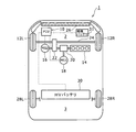
図1は、本発明の一実施形態である電力回路の冷却構造を含む電力制御ユニット10を搭載したハイブリッド自動車1の構成を示す概略図である。ハイブリッド自動車1は、駆動輪である前輪12R,12Lを駆動するための動力源として、内燃機関である四気筒のエンジン14と、電動機であるモータジェネレータ16とを備える。また、ハイブリッド自動車1は、車両の減速時や制動時に前輪12R,12Lの回転を利用して発電する発電機としてのモータジェネレータ18も備えている。
FIG. 1 is a schematic diagram showing a configuration of a hybrid vehicle 1 equipped with a
エンジン14および2つのモータジェネレータ16,18は、車両前部のエンジンルームまたはエンジンコンパートメント2内に搭載されている。エンジン14による駆動力は、動力分割機構20および減速機22を介して、前輪用車軸24に伝達されるようになっている。また、モータジェネレータ16による駆動力は、減速機22を介して前輪用車軸24に伝達されるようになっている。
The
PCUケース10は、エンジンルーム2内においてラジエータ26の直ぐ後ろ側に配置されて車両本体に固定されている。PCUケース10内のPCUは、複数のインテリジェントパワーモジュール等の電力素子を含むインバータ、リアクトル等を含む昇降圧コンバータ、ならびに、スイッチング素子およびトランス等を含むDC/DCコンバータの複数の電力回路で構成され、電力ラインを介してモータジェネレータ16,18にそれぞれ接続されている。
The
車両後部の後輪28R,28L間にほぼ対応する位置、より詳細には後部座席(図示せず)と後部トランクルーム3との間には、例えば288Vの直流電圧を出力可能なHVバッテリ30が搭載されている。HVバッテリ30は、ニッケル水素電池またはリチウムイオン電池等の二次電池で構成され、電力ラインを介してPCUケース10内のPCUに接続されている。
An
エンジンルーム2内には、補機バッテリ31も搭載されている。補機バッテリ31は、一般車載用としての定格電圧12Vの鉛二次電池で構成されることができる。補機バッテリ31は、例えばランプ、オーディオ、各種ECU等の車載補機類を作動させるのに必要な電力を供給するものである。補機バッテリ31もまた、電力ラインを介してケース10内のPCUに接続されている。
An
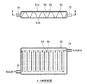
図2は、PCUケース10の斜視図である。PCUケース10は、重箱状に重ねられて矩形筐体をなす上ケース部材32、中ケース部材34および下ケース部材36で構成される。各ケース部材32,34,36は、例えばアルミダイキャストでそれぞれ形成されている。
FIG. 2 is a perspective view of the PCU
中ケース部材34の側面には、雌ねじ穴が上下方向に貫通形成されているボス部38を一体に有する。一方、上ケース部材32および下ケース部材36の側面には、上記ボス部38に対応する位置に、ボルト穴40を有する耳たぶ状の固定部42がそれぞれ一体形成されている。これらの固定部42のボルト穴40にボルトを挿入してボス部38内の雌ねじにねじ込むことによって、各ケース部材32,34,36が互いに締結される。
The side surface of the
下ケース部材36の側面には、ボルト穴44を有する耳たぶ状の固定部46が一体形成されており、この固定部46を介してPCUケース10が車体本体にボルトによって固定される。また、中ケース部材34の側壁には、後述する冷却器について冷却媒体である冷却水を導入および排出するための冷媒供給管48および冷媒排出管50が貫通して設けられている。これら冷媒供給管48および冷媒排出管50は、例えばゴムホースで構成されることができる。このゴムホースを通すために中ケース部材34の側壁に形成される貫通穴は、ケース10内への浸水を防止するためにゴムホース外周に装着されるグロメット等の弾性部材によってシールされる。
An earlobe-
なお、図2ではボス部38および固定部46が1つずつしか図示されていないが、ボス部38および固定部46は、ケース10の外周側面に複数箇所設けられている。
In FIG. 2, only one
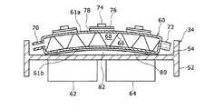
図3は、上ケース32および下ケース36を取り外した状態での中ケース部材34の断面図である。中ケース部材34は、四方を囲む側壁部52と、略H字状断面をなすように側壁部52と一体に形成されている支持板54とを有する。支持板54は、上面にねじ止め等によって載置固定される冷却器60を支持するとともに、その下面にDC/DCコンバータ62および昇降圧コンバータ64がねじ止め等によって固定されている。冷却器60の上面61aには、電力素子として6つ(図3では3つだけ図示)のインテリジェントパワーモジュール74を含むインバータ63が設置されている。
昇降圧コンバータ64は、車輪駆動時にHVバッテリ30から供給される直流電圧をインバータ供給前に昇圧する機能と、回生制動時にインバータ63から供給される直流電圧をHVバッテリ充電用に降圧する機能とを有する。また、インバータ63は、昇降圧コンバータ64とモータジェネレータ16,18との間でDC/AC変換器として機能する。さらに、DC/DCコンバータ62は、HVバッテリ30から供給される約288Vの直流電圧をランプ等の補機類作動用および補機バッテリ31充電用の12Vまで降圧する機能を有する。
なお、本実施形態においては、インバータ63が第1電力回路に相当し、DC/DCコンバータおよび書降圧コンバータ64が第2電力回路に相当するが、本発明における電力回路はこれらに限定されるものではなく、作動時に発熱を伴う他の種々の電力回路が含まれる。
FIG. 3 is a cross-sectional view of the
The step-up / down
In this embodiment, the
図4に、冷却器60の縦断面図とA−A線横断面図を示す。冷却器60は、熱伝導性が良好な例えばアルミ等の金属板で形成される矩形状筐体として構成されている。冷却器60の内部には波板状の流路形成部材66が収容されており、この流路形成部材66によって冷却水が冷却器60内を横断して平行に流れる複数の冷媒流路68が形成されている。また、冷却器60の両端面には冷媒入口管70および冷媒出口管72が突設されており、これらに上記冷媒供給管48および冷媒排出管50がそれぞれ接続されることになる。
In FIG. 4, the longitudinal cross-sectional view and AA line cross-sectional view of the cooler 60 are shown. The cooler 60 is configured as a rectangular casing made of a metal plate such as aluminum having good thermal conductivity. A corrugated flow
図3を再び参照すると、インバータ63を構成するインテリジェントパワーモジュール74は、導電性パターンが形成されたセラミック製の絶縁板(絶縁部材)76の上面にはんだ付けされた後、冷却器60の上面61aにろう付け78によって固着されている。セラミック製の絶縁板76の熱膨張率よりも冷却器60を構成する金属板の熱膨張率の方が大きいことから、ろう付け時の熱膨張の影響によって製造時には平坦面であった冷却器60の上面61aが上方へ凸状に反った湾曲面となり、これに伴って冷却器60の下面61bもまたほぼ同様の反りが生じる。
Referring to FIG. 3 again, the
このように下面61bが湾曲した冷却器60を支持板54上に載置して固定したとき、図5に示すように、冷却器下面61bに熱伝導材としてのペースト状のシリコングリス80を薄く塗布したとしても、平坦面である支持板54の表面との間に空気層からなる隙間82が形成されてしまうことがあった。この隙間82は、支持板54の下面に固定されているDC/DCコンバータ62および昇降圧コンバータ64に対する冷却器60による支持板54を介しての冷却性能を低下させることになる。なお、ここで隙間82が形成されないようシリコングリス80を厚く塗布することも考えられるが、シリコングリスを厚く塗布する作業には時間がかかるとともに厚くする分だけ放熱抵抗が大きくなることから、生産性や冷却効率の観点からして好ましくない。
When the cooler 60 having the curved
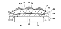
そこで、本実施形態では、図3に示すように、冷却器60の下面61bの反りに応じた形状の膨出部84を支持板54の表面に膨出成型してある。この膨出部84は、なだらかな丘陵状に湾曲して盛り上がっており、その外縁は図6に示すような略楕円状または長円状をなしている。膨出部84の盛り上がり湾曲形状や膨出高さは、インテリジェントパワーモジュール74が実装された絶縁板76をろう付けした多数の冷却器60について下面61bを実測することによって把握される反り形状に対応させてある。
Therefore, in the present embodiment, as shown in FIG. 3, the bulging
ここで、本実施形態における冷却器60、インテリジェントパワーモジュール74、絶縁板76、支持板54、DC/DCコンバータ62、昇降圧コンバータ64および膨出部84が、電力回路の冷却構造を構成する。
Here, the cooler 60, the
上記のように、本実施形態の電力回路の冷却構造によれば、冷却器60の下面61bの反りに応じた形状の膨出部84を支持板54の表面に膨出形成してあることで、支持板54の表面と冷却器60の下面61bとをほぼ隙間なく密着させることができる。これにより、冷却器60の上面61aに固着されたインバータ63を効果的に冷却できると共に、支持板54の裏面に固定されるDC/DCコンバータ62および昇降圧コンバータ64についても冷却器60による熱伝導性の支持板54を介しての冷却性能を良好に維持することができる。
As described above, according to the power circuit cooling structure of the present embodiment, the bulging
ただし、本実施形態の電力回路の冷却構造において、熱伝導材であるシリコングリスを冷却器60の下面61bに薄く塗布して膨出部84との間に介在させてもよい。これにより、支持板54の表面と冷却器60の下面61bとの密着度合いについて製品間でばらつきが生じた場合にも、シリコングリスを介在させることにより支持板54と冷却器60間の密着度を向上させることができ、DC/DCコンバータ62および昇降圧コンバータ64についての冷却器60による冷却性能が製品間で変動するのを抑えることができる。
However, in the power circuit cooling structure of the present embodiment, silicon grease, which is a heat conductive material, may be thinly applied to the
なお、上記においては支持板54に設けた膨出部84は、なだらかな丘陵状に湾曲形成されるものとして説明したが、この形状に限定されるものではなく、冷却器60の下面61bの反りにほぼ対応した形状であれば他の形状に形成されてもよい。
In the above description, the bulging
例えば、図7に示すように、支持板54上に設けられる膨出部85は階段状に膨出するよう形成されてもよい。この場合の膨出部85の各段部の外縁形状は、図8(a)に示すような略楕円状または略長円状をなしてもよいし、あるいは、図8(b)に示すような略矩形状をなしてもよい。また、このように階段状の膨出部85とした場合には、冷却器60の下面61bと支持板54の表面との間の隙間を排除すべく、ペースト状のシリコングリス80または熱伝導性の薄い弾性シートを介在させるのが好ましい。
For example, as shown in FIG. 7, the bulging
さらに、上記においては、膨出部84を中ケース部材34の支持板54と一体に成型するものとして説明したが、膨出部84が支持板54とは別部材として構成されてもよい。
Further, in the above description, the bulging
1 ハイブリッド自動車、2 エンジンルームまたはエンジンコンパートメント、3 後部トランクルーム、10 電力制御ユニット(PCU)ケース、12R,12L 前輪、14 エンジン、16,18 モータジェネレータ、20 動力分割機構、22 減速機、24 前輪用車軸、26 ラジエータ、28R,28L 後輪、30 HVバッテリ、31 補機バッテリ、32 上ケース部材、34 中ケース部材、36 下ケース部材、38 ボス部、40 ボルト穴、42 固定部、44 ボルト穴、46 固定部、48 冷媒供給管、50 冷媒排出管、52 側壁部、54 支持板、60 冷却器、61a 上面、61b 下面、62 DC/DCコンバータ、63 インバータ、64 昇降圧コンバータ、66 流路形成部材、68 冷媒流路、70 冷媒入口管、72 冷媒出口管、74 インテリジェントパワーモジュール、76 絶縁板、80 シリコングリス、82 隙間、84 膨出部、85 膨出部。
1 Hybrid vehicle, 2 engine room or engine compartment, 3 rear trunk room, 10 power control unit (PCU) case, 12R, 12L front wheel, 14 engine, 16, 18 motor generator, 20 power split mechanism, 22 reduction gear, 24 for front wheel Axle, 26 Radiator, 28R, 28L Rear wheel, 30 HV battery, 31 Auxiliary battery, 32 Upper case member, 34 Middle case member, 36 Lower case member, 38 Boss part, 40 bolt hole, 42 fixing part, 44 bolt hole , 46 fixed part, 48 refrigerant supply pipe, 50 refrigerant discharge pipe, 52 side wall part, 54 support plate, 60 cooler, 61a upper surface, 61b lower surface, 62 DC / DC converter, 63 inverter, 64 step-up / down converter, 66 flow path Forming member, 68 refrigerant flow path, 7 Refrigerant inlet pipe, 72 refrigerant outlet pipe, 74 an intelligent power module, 76 insulating
Claims (2)
冷却器の他方面と支持板の表面との間に熱伝導材を介在させてあることを特徴とする電力回路の冷却構造。 The power circuit cooling structure according to claim 1,
A cooling structure for a power circuit, wherein a heat conducting material is interposed between the other surface of the cooler and the surface of the support plate.
Priority Applications (1)
| Application Number | Priority Date | Filing Date | Title |
|---|---|---|---|
| JP2008036346A JP2009194331A (en) | 2008-02-18 | 2008-02-18 | Cooling structure of power circuit |
Applications Claiming Priority (1)
| Application Number | Priority Date | Filing Date | Title |
|---|---|---|---|
| JP2008036346A JP2009194331A (en) | 2008-02-18 | 2008-02-18 | Cooling structure of power circuit |
Publications (1)
| Publication Number | Publication Date |
|---|---|
| JP2009194331A true JP2009194331A (en) | 2009-08-27 |
Family
ID=41076044
Family Applications (1)
| Application Number | Title | Priority Date | Filing Date |
|---|---|---|---|
| JP2008036346A Withdrawn JP2009194331A (en) | 2008-02-18 | 2008-02-18 | Cooling structure of power circuit |
Country Status (1)
| Country | Link |
|---|---|
| JP (1) | JP2009194331A (en) |
Cited By (4)
| Publication number | Priority date | Publication date | Assignee | Title |
|---|---|---|---|---|
| JP2012064724A (en) * | 2010-09-15 | 2012-03-29 | Aisin Aw Co Ltd | Semiconductor cooling device and driving device for vehicle |
| KR101510868B1 (en) | 2014-08-22 | 2015-04-10 | 씨엔에이치반도체(주) | Apparatus for cooling circuit board |
| JP2015220977A (en) * | 2014-05-14 | 2015-12-07 | 現代自動車株式会社Hyundaimotor Company | Hybrid power control apparatus for vehicle |
| JP2019091784A (en) * | 2017-11-14 | 2019-06-13 | トヨタ自動車株式会社 | Power control unit and on-vehicle structure thereof |
-
2008
- 2008-02-18 JP JP2008036346A patent/JP2009194331A/en not_active Withdrawn
Cited By (6)
| Publication number | Priority date | Publication date | Assignee | Title |
|---|---|---|---|---|
| JP2012064724A (en) * | 2010-09-15 | 2012-03-29 | Aisin Aw Co Ltd | Semiconductor cooling device and driving device for vehicle |
| JP2015220977A (en) * | 2014-05-14 | 2015-12-07 | 現代自動車株式会社Hyundaimotor Company | Hybrid power control apparatus for vehicle |
| DE102014225033B4 (en) | 2014-05-14 | 2024-02-08 | Hyundai Motor Company | Hybrid energy control device for a vehicle |
| DE102014225033B8 (en) | 2014-05-14 | 2024-04-18 | Hyundai Motor Company | Hybrid energy control device for a vehicle |
| KR101510868B1 (en) | 2014-08-22 | 2015-04-10 | 씨엔에이치반도체(주) | Apparatus for cooling circuit board |
| JP2019091784A (en) * | 2017-11-14 | 2019-06-13 | トヨタ自動車株式会社 | Power control unit and on-vehicle structure thereof |
Similar Documents
| Publication | Publication Date | Title |
|---|---|---|
| JP4708459B2 (en) | Power converter | |
| JP4850564B2 (en) | Power converter | |
| JP4931458B2 (en) | Power converter | |
| JP3867060B2 (en) | Vehicle power supply system | |
| JP4611820B2 (en) | Cooling device for electric unit for vehicle | |
| US10828992B2 (en) | Fuel cell unit | |
| EP2432106A1 (en) | Electric vehicle, and method for cooling vehicular dc/dc-converter | |
| JP5161533B2 (en) | Battery module and battery pack | |
| JP2012041033A (en) | Heating part cooling structure for hybrid electric automobile | |
| JP5184218B2 (en) | Inverter unit with capacitor | |
| KR20090132031A (en) | Power control unit for fuel cell vehicle | |
| JP2006286676A (en) | Electric circuit module and power conversion apparatus mounting it, and vehicle-mounted electrical machine system | |
| JP2010110143A (en) | Power conversion device and electric vehicle | |
| JP2009261125A (en) | Power control unit | |
| JP2007220794A (en) | Capacitor device | |
| US20080310109A1 (en) | Cooling structure for high voltage electrical parts of a hybrid electric vehicle | |
| JP2010183763A (en) | Power converter | |
| WO2018207240A1 (en) | Cooling structure of power conversion device | |
| JP2005057928A (en) | On-vehicle unit | |
| JP2009194331A (en) | Cooling structure of power circuit | |
| JP2020022287A (en) | Power conversion device | |
| JP2006253544A (en) | Capacitor device | |
| JP4997056B2 (en) | Bus bar structure and power converter using the same | |
| JP6147893B2 (en) | Power converter | |
| JP2006197723A (en) | Motor drive device |
Legal Events
| Date | Code | Title | Description |
|---|---|---|---|
| A621 | Written request for application examination |
Free format text: JAPANESE INTERMEDIATE CODE: A621 Effective date: 20100709 |
|
| A761 | Written withdrawal of application |
Free format text: JAPANESE INTERMEDIATE CODE: A761 Effective date: 20110322 |