JP2009192478A - Magnetic substance detector - Google Patents
Magnetic substance detector Download PDFInfo
- Publication number
- JP2009192478A JP2009192478A JP2008036035A JP2008036035A JP2009192478A JP 2009192478 A JP2009192478 A JP 2009192478A JP 2008036035 A JP2008036035 A JP 2008036035A JP 2008036035 A JP2008036035 A JP 2008036035A JP 2009192478 A JP2009192478 A JP 2009192478A
- Authority
- JP
- Japan
- Prior art keywords
- phase difference
- magnetic
- magnetic substance
- concentration
- difference data
- Prior art date
- Legal status (The legal status is an assumption and is not a legal conclusion. Google has not performed a legal analysis and makes no representation as to the accuracy of the status listed.)
- Pending
Links
- 239000000126 substance Substances 0.000 title claims abstract description 56
- 238000001514 detection method Methods 0.000 claims abstract description 43
- 239000000696 magnetic material Substances 0.000 claims description 21
- 238000005070 sampling Methods 0.000 claims description 17
- 230000007274 generation of a signal involved in cell-cell signaling Effects 0.000 claims 1
- 239000002245 particle Substances 0.000 description 9
- 238000010586 diagram Methods 0.000 description 8
- 238000000034 method Methods 0.000 description 7
- 230000008859 change Effects 0.000 description 5
- 239000003990 capacitor Substances 0.000 description 3
- 230000008878 coupling Effects 0.000 description 3
- 238000010168 coupling process Methods 0.000 description 3
- 238000005859 coupling reaction Methods 0.000 description 3
- 230000035699 permeability Effects 0.000 description 3
- 230000008569 process Effects 0.000 description 2
- 230000000630 rising effect Effects 0.000 description 2
- 230000000087 stabilizing effect Effects 0.000 description 2
- 230000003321 amplification Effects 0.000 description 1
- 238000011109 contamination Methods 0.000 description 1
- 230000003111 delayed effect Effects 0.000 description 1
- 238000003199 nucleic acid amplification method Methods 0.000 description 1
- 230000004044 response Effects 0.000 description 1
- 238000011895 specific detection Methods 0.000 description 1
Images


Classifications
-
- G—PHYSICS
- G03—PHOTOGRAPHY; CINEMATOGRAPHY; ANALOGOUS TECHNIQUES USING WAVES OTHER THAN OPTICAL WAVES; ELECTROGRAPHY; HOLOGRAPHY
- G03G—ELECTROGRAPHY; ELECTROPHOTOGRAPHY; MAGNETOGRAPHY
- G03G15/00—Apparatus for electrographic processes using a charge pattern
- G03G15/06—Apparatus for electrographic processes using a charge pattern for developing
- G03G15/08—Apparatus for electrographic processes using a charge pattern for developing using a solid developer, e.g. powder developer
- G03G15/0822—Arrangements for preparing, mixing, supplying or dispensing developer
- G03G15/0848—Arrangements for testing or measuring developer properties or quality, e.g. charge, size, flowability
- G03G15/0849—Detection or control means for the developer concentration
- G03G15/0853—Detection or control means for the developer concentration the concentration being measured by magnetic means
-
- G—PHYSICS
- G03—PHOTOGRAPHY; CINEMATOGRAPHY; ANALOGOUS TECHNIQUES USING WAVES OTHER THAN OPTICAL WAVES; ELECTROGRAPHY; HOLOGRAPHY
- G03G—ELECTROGRAPHY; ELECTROPHOTOGRAPHY; MAGNETOGRAPHY
- G03G2215/00—Apparatus for electrophotographic processes
- G03G2215/06—Developing structures, details
- G03G2215/0602—Developer
-
- G—PHYSICS
- G03—PHOTOGRAPHY; CINEMATOGRAPHY; ANALOGOUS TECHNIQUES USING WAVES OTHER THAN OPTICAL WAVES; ELECTROGRAPHY; HOLOGRAPHY
- G03G—ELECTROGRAPHY; ELECTROPHOTOGRAPHY; MAGNETOGRAPHY
- G03G2215/00—Apparatus for electrophotographic processes
- G03G2215/06—Developing structures, details
- G03G2215/0634—Developing device
Landscapes
- Physics & Mathematics (AREA)
- General Physics & Mathematics (AREA)
- Investigating Or Analyzing Materials By The Use Of Magnetic Means (AREA)
- Dry Development In Electrophotography (AREA)
- Measuring Magnetic Variables (AREA)
Abstract
Description
本発明は、磁性体濃度を検出する磁性体検出装置に関する。 The present invention relates to a magnetic substance detection device that detects a magnetic substance concentration.
電子写真方式や静電記録方式の画像形成装置が備える現像装置には、トナー粒子とキャリア粒子を主成分とした二成分現像剤が広く用いられている。特に、フルカラーやマルチカラー画像を形成するカラー画像形成装置には、画像の色味などの観点から、現像装置として二成分現像装置を使用することが多い。 2. Description of the Related Art Two-component developers mainly composed of toner particles and carrier particles are widely used in developing devices included in electrophotographic and electrostatic recording image forming apparatuses. In particular, in a color image forming apparatus that forms a full-color or multi-color image, a two-component developing device is often used as a developing device from the viewpoint of the color of an image.
周知のように、この二成分現像剤のトナー濃度、即ち、キャリア粒子及びトナー粒子の合計重量に対するトナー粒子重量の割合は、画像品質を安定化させる上で極めて重要な要素になっている。 As is well known, the toner concentration of the two-component developer, that is, the ratio of the toner particle weight to the total weight of the carrier particles and the toner particles is a very important factor in stabilizing the image quality.
現像剤のトナー粒子は現像時に消費され、トナー濃度が変化する。このため、現像剤濃度制御装置を使用して適時現像剤のトナー濃度を正確に検出し、その変化に応じてトナー補給を行い、トナー濃度を常に一定に制御し、画像の品位を保持する必要がある。 The toner particles of the developer are consumed during development, and the toner density changes. For this reason, it is necessary to accurately detect the toner concentration of the developer in a timely manner using a developer concentration control device, replenish the toner in accordance with the change, and always control the toner concentration to be constant to maintain the image quality. There is.
トナー濃度の検出手段としては、トナー汚れに対する問題がなく、安定した濃度検出が可能な検出な磁性体検出装置が多く用いられている。 As a toner density detecting means, a magnetic substance detecting device capable of detecting a stable density without causing a problem with toner contamination is often used.
この磁性体検出装置は、現像剤の磁性キャリア(磁性のキャリア粒子)と非磁性トナーの混合比率による見かけの透磁率を検出する装置であり、その検出結果を基に、現像装置内のトナー濃度を求めることができる。 This magnetic body detection device is a device that detects an apparent magnetic permeability based on the mixing ratio of magnetic carrier (magnetic carrier particles) of developer and non-magnetic toner. Based on the detection result, the toner concentration in the development device Can be requested.
例えば、現像剤の見かけの透磁率が大きいと検出された場合、一定体積内で現像剤中のキャリア粒子が占める割合が多くなった状態、即ち、トナー濃度が低くなった状態であると認識することができる。その場合、画像形成装置はトナー補給を開始する。 For example, when it is detected that the apparent permeability of the developer is large, it is recognized that the proportion of carrier particles in the developer is increased within a certain volume, that is, the toner concentration is reduced. be able to. In that case, the image forming apparatus starts toner supply.
逆に、見かけの透磁率が小さくなった場合、一定体積内で現像剤中のキャリア粒子が占める割合が少なくなった状態、即ちトナー濃度が高くなった状態であると認識することができる。その場合、画像形成装置はトナー補給を停止する。 On the contrary, when the apparent magnetic permeability becomes small, it can be recognized that the proportion of the carrier particles in the developer is reduced within a certain volume, that is, the toner concentration is high. In that case, the image forming apparatus stops toner supply.
上記の磁性体検出装置として、差動トランスを用いた装置が知られており、図6に示すような、磁性体検出装置を小型化する提案がされている(例えば、特許文献1)。 A device using a differential transformer is known as the above-described magnetic body detection device, and a proposal for downsizing the magnetic body detection device as shown in FIG. 6 has been made (for example, Patent Document 1).
図6は、従来例に係る磁性体検出装置の概略構成図である。 FIG. 6 is a schematic configuration diagram of a magnetic body detection device according to a conventional example.
図6において、差動トランス100は、駆動コイル104と105が差動結線され、出力コイル106を有する。
In FIG. 6, the
交流信号発生器101は、所定の電気特性を有する入力信号(交流信号)Einを、駆動コイル104と105に対して入力することにより、駆動コイル104、105を駆動する。また、交流信号発生器101は、抵抗R1を介して出力コイル106と接続することにより、出力コイル106にて出力される出力信号Eoutを安定化させる。
The
増幅器102は、出力コイル106から出力される出力信号Eoutを増幅する。ここで出力信号Eoutは、入力信号Einに対して磁性体の濃度に応じた位相差を有している。
The
即ち、位相差検出器103において、駆動コイル104、105に入力する入力信号Einと、出力コイル106より増幅器102を介して出力される出力信号Eoutの位相差を検出することで、調整制御ユニット107で磁性体の濃度を求めることができる。
しかしながら、図6に示す上記従来の磁性体検出装置において、磁性体の濃度に応じて出力される位相差の信号は、磁性体の濃度が一定の場合であっても、磁性体の流動状態に対して、変動し易いという課題がある。 However, in the conventional magnetic substance detection apparatus shown in FIG. 6, the phase difference signal output according to the concentration of the magnetic substance indicates the flow state of the magnetic substance even when the concentration of the magnetic substance is constant. On the other hand, there is a problem that it is likely to fluctuate.
即ち、濃度が一定であっても密度分布にムラを持った磁性体が流動している場合、磁性体検出装置が検出する位相差の信号は、サンプリングするタイミングに応じて変化が生ずる。 That is, even when the concentration is constant, when a magnetic material having uneven density distribution is flowing, the phase difference signal detected by the magnetic material detection device changes according to the sampling timing.
このような場合には、磁性体の濃度は一定であるにもかかわらず、磁性体濃度が変化したと誤認識してしまうことになる。 In such a case, although the concentration of the magnetic material is constant, it is erroneously recognized that the magnetic material concentration has changed.
本発明の目的は、密度分布にムラを持った磁性体が流動している場合においても、磁性体濃度を正確に検出することができる磁性体検出装置を提供することにある。 An object of the present invention is to provide a magnetic substance detection device capable of accurately detecting a magnetic substance concentration even when a magnetic substance having uneven density distribution is flowing.
上記目的を達成するために、請求項1記載の磁性体検出装置は、磁性体環境に応じた磁性体の検出信号を出力する出力コイルと前記出力コイルに差動結線され、所定の電気特性を有する交流信号により駆動される駆動コイルとを有するトランスと、前記所定の電気特性を有する交流信号を発生させる交流信号発生手段と、前記交流信号発生手段により発生される前記所定の電気特性を有する交流信号と前記駆動コイルが駆動されることにより前記出力コイルより出力される前記検出信号との位相差を示す位相差データを検出する位相差検出手段と、前記磁性体環境に設けられ、停止状態及び稼動状態に切り替えられ、前記稼動状態において前記磁性体環境の前記磁性体を流動させる稼動手段と、前記稼動手段の前記稼動状態において、前記位相差検出手段により検出された前記位相差データに基づき、前記磁性体環境における前記磁性体の濃度を検出する制御手段とを備えることを特徴とする。 In order to achieve the above object, a magnetic body detection device according to claim 1 is differentially connected to an output coil for outputting a detection signal of a magnetic body according to a magnetic body environment and the output coil, and has a predetermined electrical characteristic. A transformer having a drive coil driven by the AC signal, AC signal generating means for generating an AC signal having the predetermined electrical characteristics, and AC having the predetermined electrical characteristics generated by the AC signal generating means A phase difference detection means for detecting phase difference data indicating a phase difference between a signal and the detection signal output from the output coil when the drive coil is driven; and provided in the magnetic material environment; An operating means that is switched to an operating state and causes the magnetic material in the magnetic environment to flow in the operating state; and in the operating state of the operating means, Based on the phase difference data detected by the difference detecting means, and a controlling means for detecting the concentration of the magnetic material in the magnetic environment.
本発明の磁性体検出装置によれば、密度分布にムラを持った磁性体が流動している場合においても、磁性体濃度を正確に検出することができる。 According to the magnetic substance detection device of the present invention, the magnetic substance concentration can be accurately detected even when a magnetic substance having uneven density distribution is flowing.
以下、本発明の実施の形態を図面を参照しながら詳細に説明する。 Hereinafter, embodiments of the present invention will be described in detail with reference to the drawings.
図1は、本発明の実施の形態に係る磁性体検出装置の概略構成図である。 FIG. 1 is a schematic configuration diagram of a magnetic body detection device according to an embodiment of the present invention.
図1において、差動トランス100は、差動結線された駆動コイル104と105及び駆動コイル104と105に差動結線された出力コイル106を有する。
In FIG. 1, the
交流信号発生器101は、所定の電気特性を有する入力信号(交流信号)Einを、駆動コイル104と105に対して入力することにより、駆動コイル104、105を駆動する。また、交流信号発生器101は、抵抗R1を介して出力コイル106と接続することにより、出力コイル106にて出力される出力信号(磁性体環境に応じた検出信号)Eoutを安定化させる。
The
増幅器102は、出力コイル106から出力される出力信号を増幅する。位相差検出器103は、駆動コイル104、105に入力する入力信号Einと、出力コイル106より増幅器102を介して出力される出力信号Eoutが入力され、両信号の位相差を検出する。
The
ここで、検出すべき磁性体は、磁性体検出装置の駆動コイル105側に対向される。磁性体の濃度に応じて、駆動コイル104及び出力コイル106の磁性体結合力と、駆動コイル105及び出力コイル106の磁性体結合力との大小関係が変化し、その変化が出力コイル106からの出力信号Eoutの位相の変化となって表れる。
Here, the magnetic body to be detected is opposed to the
即ち、駆動コイル104、105に入力する入力信号Einと、出力コイル106より増幅器102を介して出力される出力信号Eoutの位相差から、磁性体の濃度を検出することができる。
That is, the magnetic substance concentration can be detected from the phase difference between the input signal Ein input to the
調整制御ユニット107(制御手段)は、交流信号発生器101により発生される入力信号Ein及び、位相差検出器103により検出される位相差から、磁性体の濃度を検出している。また、調整制御ユニット107は、磁性体Mを流動させる稼動器110を制御する。
The adjustment control unit 107 (control means) detects the magnetic substance concentration from the input signal Ein generated by the
稼動器110は、調整制御ユニット107によって回転状態及び、停止状態に切り替えられるものであり、回転状態において磁性体Mを流動させ、磁性体Mを所定の方向へ搬送する役割を有するものである。
The
ここで磁性体Mは、稼動器110によって流動されるため、磁性体Mの密度分布に粗密が生じる。従って、磁性体Mが流動している状態において、たとえ、磁性体Mの濃度分布がほぼ均一であっても、濃度検出をするタイミングによって、磁性体濃度の検出値にばらつきが生じる。
Here, since the magnetic body M is flowed by the
ここで、濃度検出をするタイミングとは、駆動コイル104、105に入力する入力信号Einと、出力コイル106より増幅器102を介して出力される出力信号Eoutの位相差データ(位相差情報)を収集(サンプリング)するタイミングである。
Here, the concentration detection timing refers to collecting phase difference data (phase difference information) between the input signal Ein input to the
そこで、本実施の形態では、磁性体Mの濃度を正確に求めるために、稼動器110が約1回転する期間を、位相差情報をサンプリングする最小単位の期間として、そのサンプリング期間に複数の位相差データをサンプリングし、該複数の位相差データより磁性体Mの濃度を検出するようにしている。
Therefore, in the present embodiment, in order to accurately obtain the concentration of the magnetic substance M, the period in which the
具体的な検出方法については図3を用いて後述する。 A specific detection method will be described later with reference to FIG.
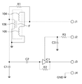
図2に、図1の磁性体検出装置の電気回路図の具体例を示す図である。 FIG. 2 is a diagram showing a specific example of an electric circuit diagram of the magnetic substance detection device of FIG.
図2の例は、本発明を限定するものではない。また、図1と符号が重複する部分においては、説明を割愛する。 The example of FIG. 2 does not limit the present invention. Further, in the portion where the reference numerals overlap with those in FIG.
図2において、磁性体検出装置は、外部構成手段との接続コネクタJ1〜J4を備える。 In FIG. 2, the magnetic body detection device includes connection connectors J1 to J4 with external configuration means.
接続コネクタJ1には、図1における交流信号発生器101からの入力信号Einが入力される。
An input signal Ein from the
接続コネクタJ2には、電源電圧Vinが入力され、抵抗R3とコンデンサC3により形成されるフィルタ回路を介して、図1における増幅器102に相当するインバータIC1の電源電圧として使用される。R2はインバータIC1の増幅帰還抵抗である。
A power supply voltage Vin is input to the connection connector J2, and is used as a power supply voltage of the inverter IC1 corresponding to the
接続コネクタJ3からは、出力コイル106とコンデンサC1により構成される同調回路で同調され、結合コンデンサC2とインバータIC1、帰還抵抗R2により増幅された出力信号Eoutが出力される。接続コネクタJ4にはGNDが接続される。
The connection connector J3 is tuned by a tuning circuit including the
次に、図3を用いて、磁性体Mの濃度検出方式について詳述する。 Next, the method for detecting the concentration of the magnetic substance M will be described in detail with reference to FIG.
図3は、図1における稼動器が回転している状態において、濃度がほぼ均一な磁性体の位相差データを検出した場合の変化の様子を示したものであり、位相差検出器の位相差データの検出タイミングを示すタイミングチャートである。 FIG. 3 shows a change in the case where phase difference data of a magnetic material having a substantially uniform concentration is detected in a state where the actuator in FIG. 1 is rotating, and shows the phase difference of the phase difference detector. It is a timing chart which shows the detection timing of data.
横軸に経過時間[ms]、縦軸に位相差データ[a.u.:任意単位]としている。図3の1段目は、位相差検出器103が動作する基本クロックCk、2段目は、駆動コイル104、105に入力し、駆動コイル104、105を駆動する信号Einを示す。
Elapsed time [ms] on the horizontal axis and phase difference data [a. u. : Arbitrary unit]. The first stage of FIG. 3 shows a basic clock Ck for operating the
また、3段目は、出力コイル106より増幅器102を介して出力される出力信号Eoutを示す。出力信号Eoutは、前述したように、入力信号Einに対して磁性体の濃度に応じた位相差を有している。
The third stage shows an output signal Eout output from the
4段目に示すように、入力信号Einの立ち上がりエッジが入力されたときに、位相差検出器103は、基本クロックCkに基づいてカウントアップを開始する。そして、出力信号Eoutの立ち上がりエッジが入力されたときに、カウントアップを停止し、5段目に示すように、該カウント値を位相差検出器103の内部に有する記憶回路に位相差データとして一時保存する。
As shown in the fourth stage, when the rising edge of the input signal Ein is input, the
図3の5段目は、稼動器110の停止・稼動状態を示している。また6段目には、稼動器110の回転回数を示している。
The fifth row in FIG. 3 shows the stop / operation state of the
ここで、前述したように、稼動器110が稼動している状態においては、磁性体Mの濃度がほぼ均一であっても、位相差データが、位相差データをサンプリングするタイミングによって変化する。
Here, as described above, in the state in which the
例えば、稼動器110がスクリュー状に構成されている場合、スクリューの回転周期に応じて、磁性体の密度が粗または密な状態に変化し、その磁性体密度状態に応じて位相差データが変化する。
For example, when the
従って、図3の6段目に示した、稼動器110が約1回転する期間(図3において、例えば回転回数が1である期間)を、位相差データをサンプリングする最小単位の期間として、このサンプリングの期間に複数の位相差データを収集する。
Therefore, the period shown in the sixth stage of FIG. 3 in which the
本実施の形態では、稼動器110が約1回転する期間に、位相差データを3つ収集する。そして、収集した複数の位相差データに対して平均値を演算し、その平均値より磁性体Mの濃度を検出している。
In the present embodiment, three phase difference data are collected during a period in which the
尚、複数の位相差データより磁性体Mの濃度を検出する手法については、上記のように平均値を演算することに限定されず、例えば、複数のデータの積算値より磁性体の濃度を求めるようにしてもよい。 The method for detecting the concentration of the magnetic substance M from a plurality of phase difference data is not limited to calculating the average value as described above. For example, the concentration of the magnetic substance is obtained from the integrated value of the plurality of data. You may do it.
また、上記において、位相差データをサンプリングする最小単位の期間を、稼動器110が約1回転する期間よりも少ない期間とすると、稼動器110の回転によって周期的に変動する磁性体の密度変化をキャンセルできないため好ましくない。
Further, in the above, if the minimum unit period for sampling the phase difference data is set to a period shorter than the period in which the
さらに、稼動器110の回転によって周期的に変動する磁性体の密度変化をキャンセルするために、位相差データをサンプリングする期間は、稼動器110が約整数回回転する期間とするのが好ましい。
Further, in order to cancel the density change of the magnetic material that periodically varies with the rotation of the
尚、磁性体濃度を求めるためのサンプリング期間は、磁性体Mの濃度が実際に変化する速さや、稼動器110の回転速度に合わせて設定するのが好ましい。例えば、サンプリング期間を極端に長く設定すると、実際に磁性体の濃度が変動した場合の検出応答が遅れてしまうので好ましくない。
The sampling period for obtaining the magnetic substance concentration is preferably set in accordance with the speed at which the concentration of the magnetic substance M actually changes and the rotational speed of the
図4は、図1の位相差検出器で検出される、磁性体濃度に対する位相差データの特性図である。 FIG. 4 is a characteristic diagram of phase difference data with respect to the magnetic substance concentration detected by the phase difference detector of FIG.
図4において、縦軸に位相差検出器103にて検出される位相差データ[s]、横軸に磁性体濃度[a.u.:任意単位]を示す。
In FIG. 4, the vertical axis represents the phase difference data [s] detected by the
図4のように、位相差データが小さい場合には磁性体の濃度が低く、逆に位相差データが大きい場合には磁性体の濃度が高くなる。 As shown in FIG. 4, when the phase difference data is small, the concentration of the magnetic material is low. Conversely, when the phase difference data is large, the concentration of the magnetic material is high.
このような磁性体濃度に対する位相差データの関係を、予め位相差検出器103に用意しておくことによって、位相差データより磁性体濃度を求めることが可能となる。例えば、図4において、上述のようにして収集した位相差データがT[s]であった場合には、磁性体濃度はD[a.u.]と求めることができる。
By preparing such a relationship of the phase difference data with respect to the magnetic substance concentration in the
続いて、磁性体濃度の検出について、図5に示す制御フローチャートに基づいて説明する。 Next, the detection of the magnetic substance concentration will be described based on the control flowchart shown in FIG.
図5は、図1の磁性体検出装置によって実行される磁性体検出処理の手順を示すフローチャートである。 FIG. 5 is a flowchart showing a procedure of magnetic body detection processing executed by the magnetic body detection apparatus of FIG.
まず、調整制御ユニット107は、稼動器110を稼動させる(ステップS501)。
First, the
その後、調整制御ユニット107は、位相差検出器103にて検出される入力信号Einと出力信号Eoutの位相差データを取得する(ステップS502)。
Thereafter, the
上記の位相差データの取得を、所定のサンプリング期間に達するまで実施する(ステップS503)。 The acquisition of the phase difference data is performed until a predetermined sampling period is reached (step S503).
ここで、所定のサンプリング期間とは、稼動器110が約1回転する期間を最小のサンプリング期間とし、稼動器110が約整数回回転する期間に設定するとよい。
Here, the predetermined sampling period may be set to a period in which the
取得した位相差データより、調整制御ユニット107に予め備えておいた、磁性体濃度に対する位相差データの関係を用いて、磁性体濃度を検出する(ステップS504)。 From the acquired phase difference data, the magnetic substance concentration is detected using the relationship of the phase difference data with respect to the magnetic substance concentration, which is prepared in advance in the adjustment control unit 107 (step S504).
そして調整制御ユニット107は、稼動器110を停止させて(ステップS505)、磁性体濃度の検出処理が終了する。
Then, the
尚、調整制御ユニット107は、図4に示した位相差データと磁性体濃度の関係を基にして、磁性体(現像剤)の濃度が一定に保つように制御する。
The
具体的には、磁性体濃度が高い場合は、磁性体環境に対して、非磁性体(非磁性トナー)を供給して磁性体濃度を一定に保つようにする。また、非磁性体濃度が高い場合には、磁性体環境に対して、非磁性体の供給を停止する。 Specifically, when the magnetic substance concentration is high, a non-magnetic substance (non-magnetic toner) is supplied to the magnetic environment to keep the magnetic substance concentration constant. Further, when the non-magnetic substance concentration is high, the supply of the non-magnetic substance is stopped with respect to the magnetic substance environment.
100 差動トランス
101 交流信号発生器
102 増幅器
103 位相差検出器
104、105 駆動コイル
106 出力コイル
107 調整制御ユニット
110 稼動器
DESCRIPTION OF
Claims (4)
前記所定の電気特性を有する交流信号を発生させる交流信号発生手段と、
前記交流信号発生手段により発生される前記所定の電気特性を有する交流信号と前記駆動コイルが駆動されることにより前記出力コイルより出力される前記検出信号との位相差を検出する位相差検出手段と、
前記磁性体環境に設けられ、停止状態及び稼動状態に切り替えられ、前記稼動状態において前記磁性体環境の前記磁性体を流動させる稼動手段と、
前記稼動手段の前記稼動状態において、前記位相差検出手段により検出された前記位相差データに基づき、前記磁性体環境における前記磁性体の濃度を検出する制御手段と、
を備えることを特徴とする磁性体検出装置。 A transformer having an output coil that outputs a detection signal of a magnetic material according to a magnetic environment, and a drive coil that is differentially connected to the output coil and driven by an AC signal having predetermined electrical characteristics;
AC signal generating means for generating an AC signal having the predetermined electrical characteristics;
Phase difference detection means for detecting a phase difference between the AC signal having the predetermined electrical characteristics generated by the AC signal generation means and the detection signal output from the output coil when the drive coil is driven; ,
An operating means provided in the magnetic environment, switched to a stopped state and an operating state, and causing the magnetic body in the magnetic environment to flow in the operating state;
Control means for detecting the concentration of the magnetic substance in the magnetic environment based on the phase difference data detected by the phase difference detecting means in the operating state of the operating means;
A magnetic body detection device comprising:
前記制御手段は、前記稼動手段が1回転する期間を、前記位相差データをサンプリングする最小単位のサンプリング期間として、前記最小単位のサンプリング期間において複数の前記位相差データをサンプリングするとともに、サンプリングした複数の前記位相差データを基に前記磁性体環境における前記磁性体の濃度を検出することを特徴とする請求項1記載の磁性体検出装置。 The operating means rotates in the magnetic environment,
The control means is configured to sample a plurality of the phase difference data in the minimum unit sampling period, and to sample a plurality of the phase difference data as a minimum unit sampling period for sampling the phase difference data during a period in which the operation unit makes one rotation. The magnetic body detection apparatus according to claim 1, wherein the concentration of the magnetic body in the magnetic body environment is detected based on the phase difference data.
Priority Applications (2)
| Application Number | Priority Date | Filing Date | Title |
|---|---|---|---|
| JP2008036035A JP2009192478A (en) | 2008-02-18 | 2008-02-18 | Magnetic substance detector |
| US12/372,349 US8185006B2 (en) | 2008-02-18 | 2009-02-17 | Magnetic material detecting device |
Applications Claiming Priority (1)
| Application Number | Priority Date | Filing Date | Title |
|---|---|---|---|
| JP2008036035A JP2009192478A (en) | 2008-02-18 | 2008-02-18 | Magnetic substance detector |
Publications (2)
| Publication Number | Publication Date |
|---|---|
| JP2009192478A true JP2009192478A (en) | 2009-08-27 |
| JP2009192478A5 JP2009192478A5 (en) | 2011-04-07 |
Family
ID=40955242
Family Applications (1)
| Application Number | Title | Priority Date | Filing Date |
|---|---|---|---|
| JP2008036035A Pending JP2009192478A (en) | 2008-02-18 | 2008-02-18 | Magnetic substance detector |
Country Status (2)
| Country | Link |
|---|---|
| US (1) | US8185006B2 (en) |
| JP (1) | JP2009192478A (en) |
Families Citing this family (4)
| Publication number | Priority date | Publication date | Assignee | Title |
|---|---|---|---|---|
| JP5521935B2 (en) * | 2010-09-17 | 2014-06-18 | 富士ゼロックス株式会社 | Image forming apparatus |
| CN103630602A (en) * | 2013-11-27 | 2014-03-12 | 国家电网公司 | Detection device and detection method for texture of coil of transformer type electrical equipment |
| CN107991631B (en) * | 2017-11-20 | 2020-10-13 | 哈尔滨工业大学 | Measuring method of magnetic signal measuring device independent of phase |
| CN108097902A (en) * | 2017-12-04 | 2018-06-01 | 南京钢铁股份有限公司 | A kind of method of on-line quick detection electromagnetic agitation magnetic field intensity |
Citations (7)
| Publication number | Priority date | Publication date | Assignee | Title |
|---|---|---|---|---|
| JPS63235972A (en) * | 1987-03-24 | 1988-09-30 | Tdk Corp | Toner concentration detector |
| JPH04368975A (en) * | 1991-06-18 | 1992-12-21 | Fujitsu Ltd | System for detection of toner mixing ratio of developing device |
| JPH0566671A (en) * | 1991-09-06 | 1993-03-19 | Fujitsu Ltd | Toner supplying method for developing device |
| JPH11190933A (en) * | 1997-12-25 | 1999-07-13 | Canon Inc | Image forming device |
| JP2000066502A (en) * | 1998-08-14 | 2000-03-03 | Canon Inc | Image forming device |
| JP2003057938A (en) * | 2001-08-10 | 2003-02-28 | Ricoh Co Ltd | Toner concentration detecting method |
| JP2006091299A (en) * | 2004-09-22 | 2006-04-06 | Fuji Xerox Co Ltd | Toner concentration controller and image forming apparatus |
Family Cites Families (1)
| Publication number | Priority date | Publication date | Assignee | Title |
|---|---|---|---|---|
| JP3175776B2 (en) * | 1991-01-31 | 2001-06-11 | ミノルタ株式会社 | Toner supply method |
-
2008
- 2008-02-18 JP JP2008036035A patent/JP2009192478A/en active Pending
-
2009
- 2009-02-17 US US12/372,349 patent/US8185006B2/en active Active
Patent Citations (7)
| Publication number | Priority date | Publication date | Assignee | Title |
|---|---|---|---|---|
| JPS63235972A (en) * | 1987-03-24 | 1988-09-30 | Tdk Corp | Toner concentration detector |
| JPH04368975A (en) * | 1991-06-18 | 1992-12-21 | Fujitsu Ltd | System for detection of toner mixing ratio of developing device |
| JPH0566671A (en) * | 1991-09-06 | 1993-03-19 | Fujitsu Ltd | Toner supplying method for developing device |
| JPH11190933A (en) * | 1997-12-25 | 1999-07-13 | Canon Inc | Image forming device |
| JP2000066502A (en) * | 1998-08-14 | 2000-03-03 | Canon Inc | Image forming device |
| JP2003057938A (en) * | 2001-08-10 | 2003-02-28 | Ricoh Co Ltd | Toner concentration detecting method |
| JP2006091299A (en) * | 2004-09-22 | 2006-04-06 | Fuji Xerox Co Ltd | Toner concentration controller and image forming apparatus |
Also Published As
| Publication number | Publication date |
|---|---|
| US8185006B2 (en) | 2012-05-22 |
| US20090208234A1 (en) | 2009-08-20 |
Similar Documents
| Publication | Publication Date | Title |
|---|---|---|
| JP2009192478A (en) | Magnetic substance detector | |
| US20110170890A1 (en) | Image forming device and developer supply method | |
| US6665503B2 (en) | Permeability detection apparatus, image forming apparatus or digital copier using the same, toner concentration detection apparatus, and electric conductivity detection apparatus | |
| JPH06289717A (en) | Magnetically detecting device | |
| JP2023180332A (en) | Developing device and image forming apparatus | |
| JP2009098038A (en) | Electric potential measuring device and image forming apparatus using it | |
| JP2009122240A (en) | Magnetic detection apparatus | |
| JP2007051885A (en) | Potential measurement device and potential measurement method | |
| JP5202032B2 (en) | Magnetic body detection apparatus and image forming apparatus | |
| JP2004163602A (en) | Permeability detecting device | |
| JP3957209B2 (en) | Electromagnetic characteristic detector | |
| JP4364770B2 (en) | Permeability measuring device, developing device, and image forming apparatus | |
| JP4774419B2 (en) | Magnetic body detection device, image forming apparatus or digital copying machine using the same, toner density detection device, conductor detection device | |
| JPS59164575A (en) | Toner density detector | |
| JP3391627B2 (en) | Toner density control method | |
| JP2008304646A (en) | Developing device and image forming apparatus | |
| JP2012242738A (en) | Image forming apparatus and permeability sensor adjustment method for the same | |
| JP2006171176A (en) | Toner concentration sensor | |
| JPH05340923A (en) | Magnetic detector | |
| JPH0582579B2 (en) | ||
| JP2023180333A (en) | Developing device and image forming apparatus | |
| JPH0434582A (en) | Setting method for toner density stable structure of developing device using two-component developing method | |
| JP2010014992A (en) | Image forming apparatus | |
| JP2011154124A (en) | Developing device and image forming apparatus | |
| JPH01251065A (en) | Developing device |
Legal Events
| Date | Code | Title | Description |
|---|---|---|---|
| A521 | Request for written amendment filed |
Free format text: JAPANESE INTERMEDIATE CODE: A523 Effective date: 20110218 |
|
| A621 | Written request for application examination |
Free format text: JAPANESE INTERMEDIATE CODE: A621 Effective date: 20110218 |
|
| A977 | Report on retrieval |
Free format text: JAPANESE INTERMEDIATE CODE: A971007 Effective date: 20120712 |
|
| A131 | Notification of reasons for refusal |
Free format text: JAPANESE INTERMEDIATE CODE: A131 Effective date: 20120807 |
|
| A521 | Request for written amendment filed |
Free format text: JAPANESE INTERMEDIATE CODE: A523 Effective date: 20121004 |
|
| A131 | Notification of reasons for refusal |
Free format text: JAPANESE INTERMEDIATE CODE: A131 Effective date: 20130409 |
|
| A02 | Decision of refusal |
Free format text: JAPANESE INTERMEDIATE CODE: A02 Effective date: 20130910 |