JP2009192046A - Hydraulic tensioner - Google Patents
Hydraulic tensioner Download PDFInfo
- Publication number
- JP2009192046A JP2009192046A JP2008035958A JP2008035958A JP2009192046A JP 2009192046 A JP2009192046 A JP 2009192046A JP 2008035958 A JP2008035958 A JP 2008035958A JP 2008035958 A JP2008035958 A JP 2008035958A JP 2009192046 A JP2009192046 A JP 2009192046A
- Authority
- JP
- Japan
- Prior art keywords
- plunger
- pressure oil
- hydraulic tensioner
- oil chamber
- bar member
- Prior art date
- Legal status (The legal status is an assumption and is not a legal conclusion. Google has not performed a legal analysis and makes no representation as to the accuracy of the status listed.)
- Pending
Links
Images


Classifications
-
- F—MECHANICAL ENGINEERING; LIGHTING; HEATING; WEAPONS; BLASTING
- F16—ENGINEERING ELEMENTS AND UNITS; GENERAL MEASURES FOR PRODUCING AND MAINTAINING EFFECTIVE FUNCTIONING OF MACHINES OR INSTALLATIONS; THERMAL INSULATION IN GENERAL
- F16H—GEARING
- F16H7/00—Gearings for conveying rotary motion by endless flexible members
- F16H7/08—Means for varying tension of belts, ropes, or chains
- F16H7/0848—Means for varying tension of belts, ropes, or chains with means for impeding reverse motion
-
- F—MECHANICAL ENGINEERING; LIGHTING; HEATING; WEAPONS; BLASTING
- F16—ENGINEERING ELEMENTS AND UNITS; GENERAL MEASURES FOR PRODUCING AND MAINTAINING EFFECTIVE FUNCTIONING OF MACHINES OR INSTALLATIONS; THERMAL INSULATION IN GENERAL
- F16H—GEARING
- F16H7/00—Gearings for conveying rotary motion by endless flexible members
- F16H7/08—Means for varying tension of belts, ropes, or chains
- F16H7/0829—Means for varying tension of belts, ropes, or chains with vibration damping means
- F16H7/0836—Means for varying tension of belts, ropes, or chains with vibration damping means of the fluid and restriction type, e.g. dashpot
-
- F—MECHANICAL ENGINEERING; LIGHTING; HEATING; WEAPONS; BLASTING
- F16—ENGINEERING ELEMENTS AND UNITS; GENERAL MEASURES FOR PRODUCING AND MAINTAINING EFFECTIVE FUNCTIONING OF MACHINES OR INSTALLATIONS; THERMAL INSULATION IN GENERAL
- F16H—GEARING
- F16H7/00—Gearings for conveying rotary motion by endless flexible members
- F16H7/18—Means for guiding or supporting belts, ropes, or chains
-
- F—MECHANICAL ENGINEERING; LIGHTING; HEATING; WEAPONS; BLASTING
- F16—ENGINEERING ELEMENTS AND UNITS; GENERAL MEASURES FOR PRODUCING AND MAINTAINING EFFECTIVE FUNCTIONING OF MACHINES OR INSTALLATIONS; THERMAL INSULATION IN GENERAL
- F16H—GEARING
- F16H7/00—Gearings for conveying rotary motion by endless flexible members
- F16H7/08—Means for varying tension of belts, ropes, or chains
- F16H2007/0802—Actuators for final output members
- F16H2007/0806—Compression coil springs
-
- F—MECHANICAL ENGINEERING; LIGHTING; HEATING; WEAPONS; BLASTING
- F16—ENGINEERING ELEMENTS AND UNITS; GENERAL MEASURES FOR PRODUCING AND MAINTAINING EFFECTIVE FUNCTIONING OF MACHINES OR INSTALLATIONS; THERMAL INSULATION IN GENERAL
- F16H—GEARING
- F16H7/00—Gearings for conveying rotary motion by endless flexible members
- F16H7/08—Means for varying tension of belts, ropes, or chains
- F16H2007/0802—Actuators for final output members
- F16H2007/0812—Fluid pressure
-
- F—MECHANICAL ENGINEERING; LIGHTING; HEATING; WEAPONS; BLASTING
- F16—ENGINEERING ELEMENTS AND UNITS; GENERAL MEASURES FOR PRODUCING AND MAINTAINING EFFECTIVE FUNCTIONING OF MACHINES OR INSTALLATIONS; THERMAL INSULATION IN GENERAL
- F16H—GEARING
- F16H7/00—Gearings for conveying rotary motion by endless flexible members
- F16H7/08—Means for varying tension of belts, ropes, or chains
- F16H7/0848—Means for varying tension of belts, ropes, or chains with means for impeding reverse motion
- F16H2007/0853—Ratchets
-
- F—MECHANICAL ENGINEERING; LIGHTING; HEATING; WEAPONS; BLASTING
- F16—ENGINEERING ELEMENTS AND UNITS; GENERAL MEASURES FOR PRODUCING AND MAINTAINING EFFECTIVE FUNCTIONING OF MACHINES OR INSTALLATIONS; THERMAL INSULATION IN GENERAL
- F16H—GEARING
- F16H7/00—Gearings for conveying rotary motion by endless flexible members
- F16H7/08—Means for varying tension of belts, ropes, or chains
- F16H7/0848—Means for varying tension of belts, ropes, or chains with means for impeding reverse motion
- F16H2007/0859—Check valves
Abstract
Description
本発明は、例えば、車両用エンジンのタイミングベルト、またはタイミングチェーン等に適正な張力を付与するための油圧式テンショナに関するものである。 The present invention relates to a hydraulic tensioner for applying appropriate tension to, for example, a timing belt of a vehicle engine or a timing chain.
車両用エンジンのクランクシャフトとカムシャフトとの間で回転を伝達するタイミングベルトやタイミングチェーンには、これらの走行時に生じる振動を抑止して適正な張力を維持するためのチェックバルブ機構を備えた油圧式テンショナが広く用いられている。 Hydraulics equipped with a check valve mechanism for maintaining proper tension in the timing belt and timing chain that transmit rotation between the crankshaft and camshaft of the vehicle engine and suppressing vibrations generated during the running A type tensioner is widely used.
このような従来のチェックバルブ機構を備えた油圧式テンショナ500は、図12に示すように、エンジンのクランクシャフトで回転される駆動側スプロケットS1とカムシャフトに固定されている被駆動側スプロケットS2、S2の間に掛け渡されているタイミングチェーンCの弛み側でエンジン本体に取り付けられて、そのハウジング本体510の前面からプランジャ520が出没自在に突出しており、プランジャ520がエンジン本体側に揺動自在に支持されている可動レバーL1の揺動端近傍の背面を押圧することにより、可動レバーL1を介してタイミングチェーンCの弛み側に張力を付与している。
As shown in FIG. 12, a
タイミングチェーンCの張り側にはタイミングチェーンCの走行を案内する固定ガイドL2がエンジン本体側に取り付けられ、前記駆動側スプロケットS1と被駆動側スプロケットS2とは、駆動側スプロケットS1が矢印の方向に回転すると、タイミングチェーンCが矢印の方向に走行し、次いで、このタイミングチェーンCの走行によって被駆動側スプロケットS2が矢印の方向に回転し、駆動側スプロケットS1の回転が被駆動側スプロケットS2に伝達するようになっている。 A fixed guide L2 for guiding the travel of the timing chain C is attached to the tight side of the timing chain C, and the driving side sprocket S1 and the driven side sprocket S2 are arranged in the direction of the arrow. When the timing chain C rotates, the timing chain C travels in the direction of the arrow, and then the driven side sprocket S2 rotates in the direction of the arrow as the timing chain C travels, and the rotation of the driving side sprocket S1 is transmitted to the driven side sprocket S2. It is supposed to be.
そして、図13に示すように、油圧式テンショナ500は、ハウジング本体510に形成されたプランジャ収容穴511内に円柱状のプランジャ520が摺動自在に嵌挿され、このプランジャ520とプランジャ収容穴511との間に形成される高圧油室Rには、プランジャ520を突出方向に付勢するコイルスプリングからなるプランジャ付勢用ばね530が収容されている。
As shown in FIG. 13, in the
さらに、前記プランジャ収容穴511の底部には、高圧油室R内の圧油の逆流を阻止する逆止弁ユニット540が圧入固定により組み込まれている。
そして、逆止弁ユニット540は、圧油の流動を規制するチェックボール弁541と、このチェックボール弁541を内包状態で遊動させるボールガイド542と、該ボールガイド542に固着されてチェックボール弁541をボールガイド542内に封止するリテーナ543と、前記ボールガイド542に固着されてチェックボール弁541の着座で圧油の逆流を阻止するボールシート544とで構成され、高圧油室R内の圧油の逆流を阻止するようになっている。
Further, a
The
その結果、高圧油室R内の圧油はプランジャ520の外周面とプランジャ収容穴511の内周面との間の僅かな隙間からリークしてハウジング本体510の外部へ排出され、その際に生じる圧油の粘性による流動抵抗によってプランジャ520に作用する衝撃力が緩和され、衝撃力によるプランジャ520の振動が速やかに減衰されるようになっている。
(例えば、特許文献1参照)。
(For example, refer to Patent Document 1).
しかしながら、このような従来の油圧式テンショナは、エンジンの回転で駆動されるポンプにより高圧油室R内に圧油が供給されており、エンジンを停止すると高圧油室R内への圧油の供給が停止し、高圧油室R内に残留した油はプランジャ520の外周面とプランジャ収容穴511の内周面との間の僅かな隙間からリークしてハウジング本体510の外部へ排出されるため、長時間のエンジン停止の後のエンジン始動時に高圧油室R内に再び圧油が供給されて充填されるまでの時間がかかり、圧油の粘性による流動抵抗による減衰作用が作動するまでに所定の時間がかかってしまうという問題があった。
However, in such a conventional hydraulic tensioner, pressure oil is supplied into the high-pressure oil chamber R by a pump driven by the rotation of the engine, and supply of the pressure oil into the high-pressure oil chamber R when the engine is stopped. The oil remaining in the high pressure oil chamber R leaks from a slight gap between the outer peripheral surface of the
また、上記の減衰作用が作動するまでの所定の時間を短縮するために高圧油室Rの容積を小さくすると高圧油室R内に収容されるプランジャ付勢用ばね530を短く、あるいは細くせざるを得ず、油圧式テンショナとして十分な性能を発揮するために必要なある程度の長さ、太さを有する高荷重、低ばね定数のプランジャ付勢用ばねを使用できないという問題があった。
Further, if the volume of the high-pressure oil chamber R is reduced in order to shorten the predetermined time until the above-described damping action is activated, the
本発明は、前述したような従来技術の問題を解決するものであって、すなわち、本発明の目的は、長時間のエンジン停止の後のエンジン始動時に高圧油室内に再び圧油が供給されて充填されるまでの時間が短縮され減衰作用が作動するまでの時間を短縮しつつ、油圧式テンショナとして十分な性能を発揮するために必要なある程度の長さ、太さを有する高荷重、低ばね定数のプランジャ付勢用ばねを使用することができる油圧式テンショナを提供することである。 The present invention solves the problems of the prior art as described above, that is, the object of the present invention is to supply pressure oil again into the high pressure oil chamber when the engine is started after a long engine stop. High load, low spring with a certain length and thickness necessary for full performance as a hydraulic tensioner while shortening the time until filling and the time until the damping action is activated It is to provide a hydraulic tensioner that can use a constant plunger biasing spring.
本請求項1に係る発明は、ハウジング本体と、該ハウジング本体に設けられたプランジャ収容穴と、該プランジャ収容穴から摺動自在に突出するプランジャと、前記プランジャ収容穴と前記プランジャとの間に形成される高圧油室と、該高圧油室に収容されてプランジャを突出させる方向に付勢するプランジャ付勢用ばねと、前記プランジャ収容穴の底部に組み込まれて高圧油室内の圧油の逆流を阻止する逆止弁ユニットとを備えた油圧式テンショナにおいて、前記プランジャ付勢用ばねが、コイルばねからなるとともに、前記高圧油室の容積を減少させるバー部材を内側の空間に収容していることにより、前記課題を解決するものである。 According to the first aspect of the present invention, there is provided a housing body, a plunger receiving hole provided in the housing body, a plunger projecting slidably from the plunger receiving hole, and between the plunger receiving hole and the plunger. A high-pressure oil chamber formed; a plunger biasing spring that is housed in the high-pressure oil chamber and urges the plunger in a protruding direction; and a reverse flow of the pressure oil in the high-pressure oil chamber built into the bottom of the plunger housing hole. In the hydraulic tensioner provided with a check valve unit for preventing the pressure, the plunger biasing spring is formed of a coil spring, and a bar member for reducing the volume of the high pressure oil chamber is accommodated in the inner space. This solves the problem.
本請求項2に係る発明は、請求項1に記載された油圧式テンショナの構成に加えて、前記逆止弁ユニットが、前記バー部材の当接によって前記高圧油室内への圧油の流入を妨げない当接部を有することにより、前記課題をさらに解決するものである。
In the invention according to
本請求項3に係る発明は、請求項1または請求項2に記載された油圧式テンショナの構成に加えて、前記バー部材が、前記プランジャ付勢用ばねの一方の端部によって前記プランジャに押圧されていることにより、前記課題をさらに解決するものである。 According to the third aspect of the present invention, in addition to the configuration of the hydraulic tensioner according to the first or second aspect, the bar member is pressed against the plunger by one end of the plunger biasing spring. Thus, the above-described problem is further solved.
本請求項4に係る発明は、請求項3に記載された油圧式テンショナの構成に加えて、前記バー部材が、前記プランジャを前記プランジャ収容穴に最も深く収容した際、前記逆止弁ユニットに当接しない形状を有することにより、前記課題をさらに解決するものである。
In addition to the structure of the hydraulic tensioner according to
本請求項5に係る発明は、請求項1または請求項2に記載された油圧式テンショナ構成に加えて、前記プランジャ付勢用ばねの一方の端部によって前記プランジャ収容穴の底部に押圧されていることにより、前記課題をさらに解決するものである。
In addition to the hydraulic tensioner structure described in
本請求項6に係る発明は、請求項5のいずれか1つに記載された油圧式テンショナ構成に加えて、前記バー部材が、前記逆止弁ユニットから前記高圧油室内への圧油の流入を妨げない形状を有することにより、前記課題をさらに解決するものである。 According to the sixth aspect of the present invention, in addition to the hydraulic tensioner configuration according to any one of the fifth aspect, the bar member is configured to allow pressure oil to flow from the check valve unit into the high pressure oil chamber. The problem is further solved by having a shape that does not interfere with the above.
本発明の油圧式テンショナは、ハウジング本体と、該ハウジング本体に設けられたプランジャ収容穴と、該プランジャ収容穴から摺動自在に突出するプランジャと、前記プランジャ収容穴と前記プランジャとの間に形成される高圧油室と、該高圧油室に収容されてプランジャを突出させる方向に付勢するプランジャ付勢用ばねと、前記プランジャ収容穴の底部に組み込まれて高圧油室内の圧油の逆流を阻止する逆止弁ユニットとを備えたことにより、プランジャ付勢用ばねでプランジャを突出方向に付勢し、高圧油室内の圧油がプランジャの外周面とプランジャ収容穴の内周面との間の僅かな隙間からリークしてハウジング本体の外部へ排出され、その際に生じる圧油の粘性による流動抵抗によってプランジャに作用する衝撃力が緩和され、衝撃力によるプランジャの振動が速やかに減衰されるとともに、以下のような格別の効果を奏することができる。 The hydraulic tensioner according to the present invention is formed between a housing main body, a plunger receiving hole provided in the housing main body, a plunger projecting slidably from the plunger receiving hole, and the plunger receiving hole and the plunger. A high-pressure oil chamber, a plunger biasing spring that is housed in the high-pressure oil chamber and biases the plunger in a protruding direction, and a backflow of the pressure oil in the high-pressure oil chamber built into the bottom of the plunger housing hole. And a check valve unit for blocking, the plunger biasing spring biases the plunger in the protruding direction so that the pressure oil in the high pressure oil chamber is between the outer peripheral surface of the plunger and the inner peripheral surface of the plunger receiving hole. Leaking from a slight gap of the gas and discharged to the outside of the housing body, the impact force acting on the plunger is mitigated by the flow resistance due to the viscosity of the pressure oil generated at that time, With the vibration of the plunger is rapidly attenuated by the impulsive force, you are possible to achieve the special effects described below.
すなわち、本請求項1に係る発明の油圧式テンショナは、前記プランジャ付勢用ばねが、コイルばねからなるとともに、前記高圧油室の容積を減少させるバー部材を内側の空間に収容していることによって、プランジャ付勢用ばねの長さ、太さを変更することなく高圧油室の容積を減少させるため、エンジン始動時に高圧油室内に再び圧油が供給されて充填されるまでの時間が短縮され減衰作用が作動するまでの時間を短縮することができるとともに、従来の油圧式テンショナと全く変わらない長さ、太さを有する高荷重、低ばね定数のプランジャ付勢用ばねを使用することができる。 That is, in the hydraulic tensioner according to the first aspect of the present invention, the plunger biasing spring is formed of a coil spring, and a bar member for reducing the volume of the high-pressure oil chamber is accommodated in the inner space. This reduces the volume of the high-pressure oil chamber without changing the length and thickness of the plunger biasing spring, reducing the time it takes for the pressurized oil chamber to be supplied and filled again when the engine is started. It is possible to shorten the time until the damping action is activated, and to use a plunger urging spring having a length and thickness that is completely the same as a conventional hydraulic tensioner and having a low load and a low spring constant. it can.
そして、本請求項2に係る発明の油圧式テンショナは、請求項1に係る油圧式テンショナが奏する効果に加えて、前記逆止弁ユニットが、前記バー部材の当接によって前記高圧油室内への圧油の流入を妨げない当接部を有することにより、プランジャの振動の速やかな減衰に関して、バー部材を有さない従来の油圧式テンショナと同様の圧油の流入量が確保できるため、同様の減衰性能を発揮することができる。 In addition to the effect of the hydraulic tensioner according to the first aspect, the hydraulic tensioner according to the second aspect of the invention is configured so that the check valve unit is brought into the high pressure oil chamber by the contact of the bar member. By having a contact portion that does not hinder the inflow of pressure oil, it is possible to secure the same amount of pressure oil inflow as that of a conventional hydraulic tensioner that does not have a bar member for quick damping of the vibration of the plunger. Attenuation performance can be demonstrated.
また、本請求項3に係る発明の油圧式テンショナは、請求項1または請求項2に係る油圧式テンショナが奏する効果に加えて、前記バー部材が、前記プランジャ付勢用ばねの一方の端部によって前記プランジャに押圧されていることにより、プランジャが水平より上方に突出するように設置されプランジャの突出量が増加した状態において、バー部材は油が残留しない上方の空間の容積を小さくすることとなるため、より効果的に、エンジン始動時に高圧油室内に再び圧油が供給されて充填されるまでの時間が短縮され減衰作用が作動するまでの時間を短縮することができる。 Further, in the hydraulic tensioner according to the third aspect of the invention, in addition to the effect exerted by the hydraulic tensioner according to the first or second aspect, the bar member is provided at one end of the plunger biasing spring. When the plunger is pressed by the plunger, the bar member reduces the volume of the upper space where the oil does not remain in a state where the plunger protrudes upward from the horizontal and the protrusion amount of the plunger increases. Therefore, more effectively, the time until the pressurized oil is supplied again and filled in the high-pressure oil chamber when the engine is started can be shortened, and the time until the damping action is activated can be shortened.
また、本請求項4に係る発明の油圧式テンショナは、請求項3に係る油圧式テンショナが奏する効果に加えて、前記バー部材が、前記プランジャを前記プランジャ収容穴に最も深く収容した際、前記逆止弁ユニットに当接しない形状を有することにより、プランジャの振動の速やかな減衰に関して、バー部材を有さない従来の油圧式テンショナと同様の圧油の流入量が確保できるため、同様の減衰性能を発揮することができる。 In addition to the effect of the hydraulic tensioner according to the third aspect, the hydraulic tensioner according to the fourth aspect of the invention has the above-described effect when the bar member accommodates the plunger deepest in the plunger accommodation hole. By having a shape that does not come into contact with the check valve unit, the same amount of pressure oil inflow as that of a conventional hydraulic tensioner without a bar member can be secured for rapid damping of plunger vibration. Performance can be demonstrated.
また、本請求項5に係る発明の油圧式テンショナは、請求項1または請求項2に係る油圧式テンショナが奏する効果に加えて、前記バー部材が、前記プランジャ付勢用ばねの一方の端部によって前記プランジャ収容穴の底部に押圧されていることにより、プランジャが水平より下方に突出するように設置されプランジャの突出量が増加した状態において、バー部材は油が残留しない上方の空間の容積を小さくすることとなるため、より効果的に、エンジン始動時に高圧油室内に再び圧油が供給されて充填されるまでの時間が短縮され減衰作用が作動するまでの時間を短縮することができる。 Further, in the hydraulic tensioner according to the fifth aspect of the present invention, in addition to the effect exerted by the hydraulic tensioner according to the first or second aspect, the bar member has one end of the plunger biasing spring. When the plunger is pressed against the bottom of the plunger receiving hole, the plunger protrudes downward from the horizontal and the amount of protrusion of the plunger increases, so that the bar member has a volume of the upper space where no oil remains. Therefore, the time until the pressure oil is again supplied and filled in the high-pressure oil chamber when the engine is started is shortened, and the time until the damping action is activated can be shortened more effectively.
また、本請求項6に係る発明の油圧式テンショナは、請求項5に係る油圧式テンショナが奏する効果に加えて、前記バー部材が、前記逆止弁ユニットから前記高圧油室内への圧油の流入を妨げない形状を有することにより、プランジャの振動の速やかな減衰に関して、バー部材を有さない従来の油圧式テンショナと同様の圧油の流入量が確保できるため、同様の減衰性能を発揮することができる。 Further, in the hydraulic tensioner according to the sixth aspect of the invention, in addition to the effect exerted by the hydraulic tensioner according to the fifth aspect, the bar member is configured to prevent the pressure oil from the check valve unit into the high pressure oil chamber. By having a shape that does not hinder inflow, the same amount of pressure oil inflow as that of a conventional hydraulic tensioner that does not have a bar member can be secured for rapid damping of plunger vibration. be able to.
本発明の油圧式テンショナは、ハウジング本体と、該ハウジング本体に設けられたプランジャ収容穴と、該プランジャ収容穴から摺動自在に突出するプランジャと、前記プランジャ収容穴と前記プランジャとの間に形成される高圧油室と、該高圧油室に収容されてプランジャを突出させる方向に付勢するプランジャ付勢用ばねと、前記プランジャ収容穴の底部に組み込まれて高圧油室内の圧油の逆流を阻止する逆止弁ユニットとを備えた油圧式テンショナにおいて、前記プランジャ付勢用ばねが、コイルばねからなるとともに、前記高圧油室の容積を減少させるバー部材を内側の空間に収容しており、長時間のエンジン停止の後のエンジン始動時に高圧油室内に再び圧油が供給されて充填されるまでの時間が短縮され減衰作用が作動するまでの時間を短縮しつつ、油圧式テンショナとして十分な性能を発揮するために必要なある程度の長さ、太さを有する高荷重、低ばね定数のプランジャ付勢用ばねを使用することができるという効果を発揮するものであれば、その具体的な実施態様は如何なるものであっても何ら構わない。 The hydraulic tensioner according to the present invention is formed between a housing main body, a plunger receiving hole provided in the housing main body, a plunger projecting slidably from the plunger receiving hole, and the plunger receiving hole and the plunger. A high-pressure oil chamber, a plunger biasing spring that is housed in the high-pressure oil chamber and biases the plunger in a protruding direction, and a backflow of the pressure oil in the high-pressure oil chamber built into the bottom of the plunger housing hole. In the hydraulic tensioner including a check valve unit for blocking, the plunger biasing spring is a coil spring, and a bar member for reducing the volume of the high-pressure oil chamber is housed in the inner space. When the engine is started after a long engine stop, the time until the pressure oil is again supplied and filled in the high-pressure oil chamber is shortened, and the damping action is activated. The effect of being able to use a plunger urging spring with a certain length and thickness required to exhibit sufficient performance as a hydraulic tensioner while shortening the time is that it can be used. Any specific embodiment may be used as long as it exhibits.
本発明の逆止弁ユニットは、いかなる形式の逆止弁を使用しても良い。
また、バー部材の材質は鉄等の金属でも良く、樹脂等を使用しても良い。
The check valve unit of the present invention may use any type of check valve.
The material of the bar member may be a metal such as iron, or a resin or the like.
以下に、本発明の油圧式テンショナについて図面を基づいて説明する。
図1は、本発明の第1実施例である油圧式テンショナの断面図であり、図2は、図1に示す本発明の第1実施例である油圧式テンショナのバー部材の概要図であり、図3は、本発明の第2及び第3実施例である油圧式テンショナの使用例を示す説明図であり、図4は本発明の第2実施例である油圧式テンショナの使用例を示す説明図であり、図5は、本発明の第2実施例である油圧式テンショナの断面図であり、図6は、図5に示す本発明の第2実施例である油圧式テンショナのプランジャ突出時の断面図であり、図7は、本発明の第2実施例である油圧式テンショナのバー部材の概要図であり、図8は、本発明の第3実施例である油圧式テンショナの使用例を示す説明図であり、図9は、本発明の第3実施例である油圧式テンショナの断面図であり、図10は、図9に示す本発明の第3実施例である油圧式テンショナのプランジャ突出時の断面図であり、図11は、本発明の第3実施例である油圧式テンショナのバー部材の概要図である。
Hereinafter, a hydraulic tensioner according to the present invention will be described with reference to the drawings.
FIG. 1 is a sectional view of a hydraulic tensioner according to a first embodiment of the present invention, and FIG. 2 is a schematic view of a bar member of the hydraulic tensioner according to the first embodiment of the present invention shown in FIG. FIG. 3 is an explanatory view showing a usage example of the hydraulic tensioner according to the second and third embodiments of the present invention, and FIG. 4 shows a usage example of the hydraulic tensioner according to the second embodiment of the present invention. FIG. 5 is a sectional view of a hydraulic tensioner according to a second embodiment of the present invention, and FIG. 6 is a plunger protrusion of the hydraulic tensioner according to the second embodiment of the present invention shown in FIG. FIG. 7 is a schematic view of a bar member of a hydraulic tensioner according to a second embodiment of the present invention, and FIG. 8 is a diagram illustrating the use of the hydraulic tensioner according to a third embodiment of the present invention. FIG. 9 is an explanatory view showing an example, and FIG. 9 is a sectional view of a hydraulic tensioner according to a third embodiment of the present invention. FIG. 10 is a sectional view of the hydraulic tensioner according to the third embodiment of the present invention shown in FIG. 9 when the plunger protrudes, and FIG. 11 shows the hydraulic tensioner according to the third embodiment of the present invention. It is a schematic diagram of a bar member.
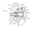
まず、本発明の第1実施例である油圧式テンショナ100は、図1に示すように、ハウジング本体110に形成されたプランジャ収容穴111内に円柱状のプランジャ120が摺動自在に嵌挿され、このプランジャ120とプランジャ収容穴111との間に形成される高圧油室Rには、プランジャ120を突出方向に付勢するコイルスプリングからなるプランジャ付勢用ばね130が収容されている。
さらに、前記プランジャ収容穴111の底部には、高圧油室R内の圧油の逆流を阻止する逆止弁ユニット140が組み込まれている。
そして、逆止弁ユニット140は、圧油の流動を規制するチェックボール弁141と、このチェックボール弁141を内包状態で遊動させるリテーナ142と、前記ボール弁141の着座で圧油の逆流を阻止するボールシート144とで構成され、高圧油室R内の圧油の逆流を阻止するようになっている。
First, in the
Further, a
The
また、本第1実施例の油圧式テンショナ100は、プランジャ120に形成したラック122とハウジング本体110に軸支されたラチェット爪体160が噛み合うことによりプランジャ120の後退が阻止されるラチェット機構を備えている。ラチェット爪体160はラチェット付勢用ばね161によりプランジャ120のラック122に向けて付勢されている。
なお、本発明において上記ラチェット機構は省略されても良い。
そして、プランジャ付勢用ばね130は油圧式テンショナとして十分な性能を発揮するために必要なある程度の長さ、太さを有する高荷重、低ばね定数を有しており、その内部の空間にバー部材150が組み込まれている。
Further, the
In the present invention, the ratchet mechanism may be omitted.
The
バー部材150は、図2に示すように、外径がプランジャ付勢用ばね130の内径よりわずかに小さく、かつ、両端がテーパ面151で円錐台状とされた中実の円筒形状に構成されており、プランジャ付勢用ばね130の伸縮や高圧油室R内の圧油の流動を妨げることなく、バー部材150の体積分だけ高圧油室Rの容積を減少させる。
また、逆止弁ユニット140のリテーナ142は、バー部材150と当接によって圧油の流入が妨げられないよう、当接部以外の部分に圧油の流入口が設けられている。
As shown in FIG. 2, the
Further, the
このように構成された本発明の第1実施例である油圧式テンショナ100によれば、油圧式テンショナとして十分な性能を発揮するために必要な長さ、太さを有する高荷重、低ばね定数のプランジャ付勢用ばねを用いつつ、高圧油R室の容積を減少させるため、高圧油室R内の油が排出された状態から再び圧油が供給されて充填されるまでの時間が短縮され、エンジン始動時に減衰作用が正常に作動するまでの時間を短縮することができるとともに、バー部材150を有さない従来の油圧式テンショナと同様の各構成部材の作動と圧油の流入量が確保できるなど、その効果は甚大である。
According to the
次に、本発明の第2実施例である油圧式テンショナ200は、図3、図4に例示するような、構造上押圧方向が水平ではないタイミングシステム等に適用するのに好適なものであって、図5に示すように、ハウジング本体210に形成されたプランジャ収容穴211内に円柱状のプランジャ220が摺動自在に嵌挿され、このプランジャ220とプランジャ収容穴211との間に形成される高圧油室Rには、プランジャ220を突出方向に付勢するコイルスプリングからなるプランジャ付勢用ばね230が収容されている。
さらに、前記プランジャ収容穴211の底部には、高圧油室R内の圧油の逆流を阻止する逆止弁ユニット240が組み込まれている。
そして、逆止弁ユニット240は、圧油の流動を規制するチェックボール弁241と、このチェックボール弁241を内包状態で遊動させるボールガイド242と、該ボールガイド242に固着されてチェックボール弁241をボールガイド242内に封止するリテーナ243と、前記ボール弁241の着座で圧油の逆流を阻止するボールシート244とで構成され、高圧油室R内の圧油の逆流を阻止するようになっている。
Next, the
Further, a
The
また、本第2実施例の油圧式テンショナ200は、プランジャ220に形成したラック222とハウジング本体210に軸支されたラチェット爪体260が噛み合うことによりプランジャ220の後退が阻止されるラチェット機構を備えている。ラチェット爪体260はラチェット付勢用ばね261によりプランジャ220のラック222に向けて付勢されている。
なお、本発明において上記ラチェット機構は省略されても良い。
そして、プランジャ付勢用ばね230は油圧式テンショナとして十分な性能を発揮するために必要なある程度の長さ、太さを有する高荷重、低ばね定数を有しており、その内部の空間にバー部材250が組み込まれている。
The
In the present invention, the ratchet mechanism may be omitted.
The
バー部材250は、図7に示すように、外径がプランジャ付勢用ばね230の内径よりわずかに小さく、かつ、一方の端部がプランジャ付勢用ばね230を受ける段付きの大径部252とされ、他端がテーパ面251で円錐台状とされた中実の円筒形状に構成されており、プランジャ付勢用ばね230の伸縮や高圧油室R内の圧油の流動を妨げることなく、バー部材250の体積分だけ高圧油室Rの容積を減少させる。
また、逆止弁ユニット240のリテーナ243は、プランジャ付勢用ばね230を受ける座を兼ねている。
As shown in FIG. 7, the
The
そして、バー部材250は、テーパ面251が逆止弁ユニット240側、段付きの大径部252がプランジャ220の突出方向側に配置され、プランジャ付勢用ばね230の両端が、逆止弁ユニット240のリテーナ243とバー部材250の段付きの大径部252によって受けられることにより、プランジャ220のプランジャ収容穴211での摺動と一体となって動くよう構成されており、プランジャ付勢用ばね230の伸縮や高圧油室R内の圧油の流動を妨げることなく、バー部材250の体積分だけ高圧油室Rの容積を減少させる。
また、バー部材250の長さは、逆止弁ユニット240のリテーナ243に当接して圧油の流入が妨げられないように設定されている。
In the
Further, the length of the
このように構成された本発明の第2実施例である油圧式テンショナ200によれば、油圧式テンショナとして十分な性能を発揮するために必要な長さ、太さを有する高荷重、低ばね定数のプランジャ付勢用ばねを用いつつ、高圧油R室の容積を減少させるため、高圧油室R内の油が排出された状態から再び圧油が供給されて充填されるまでの時間が短縮され、エンジン始動時に減衰作用が正常に作動するまでの時間を短縮することができるとともに、バー部材250を有さない従来の油圧式テンショナと同様の各構成部材の作動と圧油の流入量が確保できる。
According to the
さらに、図3、図4に示すように、プランジャ220が水平より上方に突出するように設置された場合、図6に示すように、エンジン停止時において高圧油室R内はプランジャ収容穴211の逆止弁ユニット240側に油面Sまで油が残留するため、プランジャ220の突出量が増加した状態でも、バー部材250をプランジャ220と一体となって動くよう構成することにより、エンジンの始動時に油が残留しない上方の空間の容積の増加はわずかであり、エンジン始動時に減衰作用が正常に作動するまでの時間をさらに短縮できるなど、その効果は甚大である。
Further, as shown in FIGS. 3 and 4, when the
次に、本発明の第3実施例である油圧式テンショナ300は、図3、図8に例示するような、構造上押圧方向が水平ではないタイミングシステム等に適用するのに好適なものであって、図9に示すように、ハウジング本体310に形成されたプランジャ収容穴311内に円柱状のプランジャ320が摺動自在に嵌挿され、このプランジャ320とプランジャ収容穴311との間に形成される高圧油室Rには、プランジャ320を突出方向に付勢するコイルスプリングからなるプランジャ付勢用ばね330が収容されている。
さらに、前記プランジャ収容穴311の底部には、高圧油室R内の圧油の逆流を阻止する逆止弁ユニット340が組み込まれている。
そして、逆止弁ユニット340は、圧油の流動を規制するチェックボール弁341と、このチェックボール弁341を内包状態で遊動させるボールガイド342と、該ボールガイド342に固着されてチェックボール弁341をボールガイド342内に封止するリテーナ343と、前記ボール弁341の着座で圧油の逆流を阻止するボールシート344とで構成され、高圧油室R内の圧油の逆流を阻止するようになっている。
Next, the
Further, a
The
また、本第3実施例の油圧式テンショナ300は、プランジャ320に形成したラック322とハウジング本体310に軸支されたラチェット爪体360が噛み合うことによりプランジャ320の後退が阻止されるラチェット機構を備えている。ラチェット爪体360はラチェット付勢用ばね361によりプランジャ320のラック322に向けて付勢されている。
なお、本発明において上記ラチェット機構は省略されても良い。
そして、プランジャ付勢用ばね330は油圧式テンショナとして十分な性能を発揮するために必要なある程度の長さ、太さを有する高荷重、低ばね定数を有しており、その内部の空間にバー部材350が組み込まれている。
Further, the
In the present invention, the ratchet mechanism may be omitted.
The
バー部材350は、図11に示すように、外径がプランジャ付勢用ばね330の内径よりわずかに小さく、かつ、一方の端部がプランジャ付勢用ばね330を受ける段付きの大径部352とされ、他端がテーパ面351で円錐台状とされた中実の円筒形状に構成され、さらに、大径部352の端面は当接するリテーナ343側から供給される圧油を抵抗なく通過させる溝部353が設けられており、プランジャ付勢用ばね330の伸縮や高圧油室R内の圧油の流動を妨げることなく、バー部材350の体積分だけ高圧油室Rの容積を減少させる。
また、逆止弁ユニット340のリテーナ343は、プランジャ付勢用ばね330によって押圧されるバー部材350の端面を受ける座を兼ねるとともに、バー部材350の端面との当接によって圧油の流入が妨げられないよう、当接部以外の部分に圧油の流入口が設けられている。
As shown in FIG. 11, the
The
そして、バー部材350は、段付きの大径部352が逆止弁ユニット340側、テーパ面351がプランジャ320の突出方向側に配置され、プランジャ付勢用ばね330の両端が、バー部材350の段付きの大径部352とプランジャ320によって受けられることにより、プランジャ320のプランジャ収容穴311での摺動にかかわらずハウジング本体310と一体に動かないよう構成されており、プランジャ付勢用ばね330の伸縮や高圧油室R内の圧油の流動を妨げることなく、バー部材350の体積分だけ高圧油室Rの容積を減少させる。
また、バー部材350の長さは、プランジャ320に当接してプランジャ320の摺動ストロークを規制しないように設定されている。
The
The length of the
このように構成された本発明の第3実施例である油圧式テンショナ300によれば、油圧式テンショナとして十分な性能を発揮するために必要な長さ、太さを有する高荷重、低ばね定数のプランジャ付勢用ばねを用いつつ、高圧油R室の容積を減少させるため、高圧油室R内の油が排出された状態から再び圧油が供給されて充填されるまでの時間が短縮され、エンジン始動時に減衰作用が正常に作動するまでの時間を短縮することができるとともに、バー部材350を有さない従来の油圧式テンショナと同様の各構成部材の作動と圧油の流入量が確保できる。
According to the
さらに、図3、図8に示すように、プランジャ320が水平より下方に突出するように設置された場合、図10に示すように、エンジン停止時において高圧油室R内はプランジャ300のプランジャ付勢用ばね330の当接部側に油面Sまで油が残留するため、プランジャ320の突出量が増加した状態でも、バー部材350をハウジング本体310と一体となって動かないよう構成することにより、エンジンの始動時に油が残留しない上方の空間の容積の増加はわずかであり、エンジン始動時に減衰作用が正常に作動するまでの時間をさらに短縮できるなど、その効果は甚大である。
Further, as shown in FIGS. 3 and 8, when the
100,200,300,500 ・・・油圧式テンショナ
110,210,310,510 ・・・ハウジング本体
111,211,311,511 ・・・プランジャ収容穴
120,220,320,520 ・・・プランジャ
122,222,322 ・・・ラック
130,230,330,530 ・・・プランジャ付勢用ばね
140,240,340,540 ・・・逆止弁ユニット
141,241,341,541 ・・・チェックボール弁
242,342,542 ・・・ボールガイド
142,243,343,543 ・・・リテーナ
144,244,344,544 ・・・ボールシート
150,250,350 ・・・バー部材
151,251,351 ・・・テーパ面
252,352 ・・・大径部
353 ・・・溝部
160,260,360 ・・・ラチェット爪体
161,261,361 ・・・ラチェット付勢用ばね
R ・・・高圧油室
S ・・・油面
100, 200, 300, 500 ...
242,342,542 ... Ball guide 142,243,343,543 ... Retainer 144,244,344,544 ... Ball sheet 150,250,350 ... Bar member 151,251,351・ Taper surface
252,352 ... large diameter part
353...
Claims (6)
前記プランジャ付勢用ばねが、コイルばねからなるとともに、前記高圧油室の容積を減少させるバー部材を内側の空間に収容していることを特徴とする油圧式テンショナ。 A housing main body, a plunger receiving hole provided in the housing main body, a plunger protruding slidably from the plunger receiving hole, a high-pressure oil chamber formed between the plunger receiving hole and the plunger, A plunger biasing spring that is housed in the high pressure oil chamber and biases the plunger in a protruding direction, and a check valve unit that is incorporated in the bottom of the plunger housing hole and prevents the backflow of the pressure oil in the high pressure oil chamber. In the provided hydraulic tensioner,
2. The hydraulic tensioner according to claim 1, wherein the plunger biasing spring comprises a coil spring and a bar member for reducing the volume of the high pressure oil chamber is accommodated in an inner space.
Priority Applications (6)
| Application Number | Priority Date | Filing Date | Title |
|---|---|---|---|
| JP2008035958A JP2009192046A (en) | 2008-02-18 | 2008-02-18 | Hydraulic tensioner |
| GB0900359.1A GB2457352B (en) | 2008-02-18 | 2009-01-09 | Hydraulic tensioner |
| US12/354,292 US8033938B2 (en) | 2008-02-18 | 2009-01-15 | Hydraulic tensioner |
| CNA2009100087042A CN101514643A (en) | 2008-02-18 | 2009-01-21 | Hydraulic tensioner |
| KR1020090006899A KR20090089251A (en) | 2008-02-18 | 2009-01-29 | Hydraulic tensioner |
| DE102009008804A DE102009008804A1 (en) | 2008-02-18 | 2009-02-05 | Hydraulic tensioner |
Applications Claiming Priority (1)
| Application Number | Priority Date | Filing Date | Title |
|---|---|---|---|
| JP2008035958A JP2009192046A (en) | 2008-02-18 | 2008-02-18 | Hydraulic tensioner |
Publications (1)
| Publication Number | Publication Date |
|---|---|
| JP2009192046A true JP2009192046A (en) | 2009-08-27 |
Family
ID=40379392
Family Applications (1)
| Application Number | Title | Priority Date | Filing Date |
|---|---|---|---|
| JP2008035958A Pending JP2009192046A (en) | 2008-02-18 | 2008-02-18 | Hydraulic tensioner |
Country Status (6)
| Country | Link |
|---|---|
| US (1) | US8033938B2 (en) |
| JP (1) | JP2009192046A (en) |
| KR (1) | KR20090089251A (en) |
| CN (1) | CN101514643A (en) |
| DE (1) | DE102009008804A1 (en) |
| GB (1) | GB2457352B (en) |
Families Citing this family (7)
| Publication number | Priority date | Publication date | Assignee | Title |
|---|---|---|---|---|
| JP4611394B2 (en) * | 2008-02-18 | 2011-01-12 | 株式会社椿本チエイン | Hydraulic tensioner |
| DE102008059191A1 (en) * | 2008-11-27 | 2010-06-02 | Schaeffler Kg | Clamping unit for a traction device clamping device |
| JP2011226534A (en) * | 2010-04-19 | 2011-11-10 | Tsubakimoto Chain Co | Chain tensioner |
| JP6357039B2 (en) * | 2014-07-09 | 2018-07-11 | 株式会社椿本チエイン | Tensioner |
| US9714694B2 (en) * | 2015-09-01 | 2017-07-25 | GM Global Technology Operations LLC | High damping low force hydraulic strut tensioner |
| JP6378661B2 (en) * | 2015-11-16 | 2018-08-22 | 株式会社椿本チエイン | Chain tensioner |
| JP2022098902A (en) * | 2020-12-22 | 2022-07-04 | 株式会社椿本チエイン | Tensioner |
Citations (4)
| Publication number | Priority date | Publication date | Assignee | Title |
|---|---|---|---|---|
| JPH0478360U (en) * | 1990-11-20 | 1992-07-08 | ||
| JPH07158703A (en) * | 1993-09-23 | 1995-06-20 | Borg Warner Automot Inc | Liquid-operated chain tensioner |
| JP2000145903A (en) * | 1998-09-21 | 2000-05-26 | Borg Warner Automot Inc | Hydraulic tensioner |
| JP2007255578A (en) * | 2006-03-23 | 2007-10-04 | Ntn Corp | Auto tensioner |
Family Cites Families (13)
| Publication number | Priority date | Publication date | Assignee | Title |
|---|---|---|---|---|
| JPH0478360A (en) | 1990-07-18 | 1992-03-12 | Kubota Corp | Transmission gear |
| US6716124B2 (en) * | 2000-11-29 | 2004-04-06 | Borgwarner Inc. | Hydraulic tensioner with improved pressure relief valve reactive to peak operating loads |
| DE20210622U1 (en) * | 2002-07-09 | 2003-11-20 | Winklhofer & Soehne Gmbh | Hydraulic tensioning device for especially timing chain of internal combustion engine has pressure chamber ventilation device with cap pressurized by spring unit onto base of recess in pressure chamber |
| JP4169576B2 (en) * | 2002-10-28 | 2008-10-22 | Ntn株式会社 | Hydraulic tensioner |
| US7641575B2 (en) | 2004-04-09 | 2010-01-05 | Tsubakimoto Chain Co. | Hydraulic tensioner |
| US7691017B2 (en) * | 2004-04-23 | 2010-04-06 | Borgwarner Morse Tec Japan K.K. | Hydraulic tensioner |
| DE102004056623A1 (en) * | 2004-11-24 | 2006-07-06 | Schaeffler Kg | Hydraulic tensioner for a traction means of an internal combustion engine |
| US20070243961A1 (en) * | 2006-02-03 | 2007-10-18 | Ford Global Technologies, Llc | Ratcheting tensioner with override |
| DE102007023671B4 (en) * | 2006-06-15 | 2023-03-16 | Ntn Corp. | chain tensioner |
| DE102007036119A1 (en) | 2007-01-27 | 2008-07-31 | Schaeffler Kg | Hydraulic chain tensioner for a traction mechanism with a cast housing |
| DE202007002456U1 (en) | 2007-02-20 | 2008-07-03 | Iwis Motorsysteme Gmbh & Co. Kg | Clamping device with dynamic venting valve |
| DE202007004988U1 (en) * | 2007-04-04 | 2008-08-07 | Iwis Motorsysteme Gmbh & Co. Kg | Clamping device with temperature-dependent valve |
| JP4611394B2 (en) * | 2008-02-18 | 2011-01-12 | 株式会社椿本チエイン | Hydraulic tensioner |
-
2008
- 2008-02-18 JP JP2008035958A patent/JP2009192046A/en active Pending
-
2009
- 2009-01-09 GB GB0900359.1A patent/GB2457352B/en not_active Expired - Fee Related
- 2009-01-15 US US12/354,292 patent/US8033938B2/en not_active Expired - Fee Related
- 2009-01-21 CN CNA2009100087042A patent/CN101514643A/en active Pending
- 2009-01-29 KR KR1020090006899A patent/KR20090089251A/en not_active Application Discontinuation
- 2009-02-05 DE DE102009008804A patent/DE102009008804A1/en not_active Withdrawn
Patent Citations (4)
| Publication number | Priority date | Publication date | Assignee | Title |
|---|---|---|---|---|
| JPH0478360U (en) * | 1990-11-20 | 1992-07-08 | ||
| JPH07158703A (en) * | 1993-09-23 | 1995-06-20 | Borg Warner Automot Inc | Liquid-operated chain tensioner |
| JP2000145903A (en) * | 1998-09-21 | 2000-05-26 | Borg Warner Automot Inc | Hydraulic tensioner |
| JP2007255578A (en) * | 2006-03-23 | 2007-10-04 | Ntn Corp | Auto tensioner |
Also Published As
| Publication number | Publication date |
|---|---|
| US20090209376A1 (en) | 2009-08-20 |
| DE102009008804A1 (en) | 2009-08-20 |
| GB2457352B (en) | 2012-04-04 |
| US8033938B2 (en) | 2011-10-11 |
| GB2457352A (en) | 2009-08-19 |
| CN101514643A (en) | 2009-08-26 |
| GB0900359D0 (en) | 2009-02-11 |
| KR20090089251A (en) | 2009-08-21 |
Similar Documents
| Publication | Publication Date | Title |
|---|---|---|
| JP4611394B2 (en) | Hydraulic tensioner | |
| JP2009192046A (en) | Hydraulic tensioner | |
| JP4376278B2 (en) | Hydraulic tensioner | |
| JP2009192031A (en) | Hydraulic tensioner | |
| JP3962052B2 (en) | Hydraulic tensioner | |
| KR100538973B1 (en) | Hydraulic Type Tensioner with Relief Valve | |
| JP4751842B2 (en) | Hydraulic tensioner | |
| JP5205070B2 (en) | Endless transmission belt tensioner | |
| US10024401B2 (en) | Chain tensioner | |
| JP3962054B2 (en) | Degassing hydraulic tensioner | |
| JP2008215553A (en) | Hydraulic tensioner installable at depression angle | |
| JP2009541676A (en) | Check valve with ball held by spring | |
| JP4980798B2 (en) | Auto tensioner | |
| JP2005325938A (en) | Hydraulic tensioner | |
| JP3933634B2 (en) | Hydraulic tensioner | |
| JP2009243480A (en) | Hydraulic tensioner | |
| KR102072408B1 (en) | Tensioner | |
| KR20050041887A (en) | Hydraulic tensioner | |
| JP2012017824A (en) | Chain tensioner | |
| JP2011058589A (en) | Automatic tensioner | |
| JP2009264583A (en) | Chain tensioner | |
| JP4180487B2 (en) | Hydraulic tensioner | |
| JP2007255578A (en) | Auto tensioner | |
| JP2007303646A (en) | Hydraulic automatic tensioner | |
| JP2015203467A (en) | chain tensioner |
Legal Events
| Date | Code | Title | Description |
|---|---|---|---|
| A621 | Written request for application examination |
Free format text: JAPANESE INTERMEDIATE CODE: A621 Effective date: 20100217 |
|
| A977 | Report on retrieval |
Free format text: JAPANESE INTERMEDIATE CODE: A971007 Effective date: 20100624 |
|
| A131 | Notification of reasons for refusal |
Free format text: JAPANESE INTERMEDIATE CODE: A131 Effective date: 20100629 |
|
| A521 | Written amendment |
Free format text: JAPANESE INTERMEDIATE CODE: A523 Effective date: 20100826 |
|
| A02 | Decision of refusal |
Free format text: JAPANESE INTERMEDIATE CODE: A02 Effective date: 20101021 |