JP2009190856A - Alignment transportation device - Google Patents
Alignment transportation device Download PDFInfo
- Publication number
- JP2009190856A JP2009190856A JP2008034469A JP2008034469A JP2009190856A JP 2009190856 A JP2009190856 A JP 2009190856A JP 2008034469 A JP2008034469 A JP 2008034469A JP 2008034469 A JP2008034469 A JP 2008034469A JP 2009190856 A JP2009190856 A JP 2009190856A
- Authority
- JP
- Japan
- Prior art keywords
- conveyor
- plastic
- plastics
- aligned
- width direction
- Prior art date
- Legal status (The legal status is an assumption and is not a legal conclusion. Google has not performed a legal analysis and makes no representation as to the accuracy of the status listed.)
- Granted
Links
Images

Abstract
Description
本発明は、例えば使用済みとして回収されたトレイ、容器、蓋、パック等のプラスチックを一列に整列させて搬送する整列搬送装置に関し、主として、それらプラスチックを材質に応じて選別する装置(選別装置)に組み込まれ、あるいはその選別装置に対する供給装置として使用される。 The present invention relates to an aligning / conveying apparatus that conveys plastics such as trays, containers, lids, and packs collected as used, for example, in a line, and mainly sorts these plastics according to the material (sorting apparatus). Or used as a supply device for the sorting device.
従来より、プラスチックの近赤外光吸収スペクトルがその材質により特有であることを利用して、プラスチックの材質を特定しつつ、そのプラスチックを材質に応じて選別する装置が種々提案されている。そして、このような近赤外光吸収スペクトルによるプラスチックの材質の特定処理は、近赤外分光素子と近赤外領域で使用できる一次元固体撮像素子との組み合わせによる分光システム等により、極めて短い時間で行えるようになってきた。従って、上記した選別装置の処理能力は、無造作に投入されたプラスチックを一列に整列させる整列搬送装置の処理速度によって決定されることになる。 2. Description of the Related Art Conventionally, various devices have been proposed for selecting a plastic according to the material while identifying the plastic material by utilizing the fact that the near-infrared light absorption spectrum of the plastic is unique to the material. The plastic material identification process based on the near-infrared light absorption spectrum can be performed in an extremely short time by using a spectroscopic system that combines a near-infrared spectroscopic element and a one-dimensional solid-state image sensor that can be used in the near-infrared region. It has become possible to do in. Therefore, the processing capability of the above-described sorting apparatus is determined by the processing speed of the aligning and conveying apparatus that aligns plastics that are randomly input in a row.
この種の整列搬送装置としては、幅方向に傾斜して配置された移送コンベア、この幅方向に傾斜した移送コンベアの下側の辺に沿って設けられた走行ガイド、及び移送コンベア上で搬送されるプラスチックを長手方向に一列に配列させる配列手段を有する第1整列手段と、プラスチックを長手方向に一列で搬送し得る幅を有する搬送コンベア、及びこの搬送コンベアで搬送されなかったプラスチックを投入手段に戻す戻し搬送手段を有する第2整列手段とからなるものが公知である(特許文献1)。
しかしながら、上記公報所載の整列搬送装置は、廃棄プラスチック中のプラスチックボトル及びこれに形状が近い玩具等のハードプラスチックを材質別及び色別等に選別する装置に対する供給装置として考案されたものであり、例えば、(i)冷凍食品用のトレイ、(ii)弁当、赤飯、寿司、総菜、和菓子等、加工食品を入れる容器(容器と蓋が一体化したものや、別途の蓋を要するものの両方を含む)やその蓋、(iii)卵のパック、といったシート成形(真空成形)品からなるプラスチックには不向きである。 However, the aligning and conveying device described in the above publication is devised as a supply device for a device that sorts plastic bottles in waste plastic and hard plastics such as toys that are close in shape to materials and colors. For example, (i) trays for frozen foods, (ii) lunch boxes, red rice, sushi, prepared dishes, Japanese sweets, etc. And a cover thereof, and (iii) a pack of eggs, it is not suitable for plastic made of a sheet-formed (vacuum-formed) product.
なぜならば、これらプラスチックは、四角形であったり、円形や楕円形であったりと形状が多様であり、また、偏平な形状であったり、開口が広かったりするため、上下に重なった状態で搬送されてしまうことが頻繁に起こる(その結果、それらについては、下流側の選別装置において、材質を特定できなかったり、ミスジャッジが発生する)し、大きさが不均一であり、大きなものは第2整列手段の搬送コンベアに乗らず、いつまでも脱落を繰り返してしまうことが頻繁に起こる(その結果、それらについては、いつまでたっても下流側の選別装置において処理されない)からである。 This is because these plastics have a variety of shapes, such as quadrangular shapes, circular shapes, and oval shapes, are flat, and have wide openings. (As a result, in the sorting apparatus on the downstream side, the material cannot be specified or misjudgment occurs), and the size is not uniform. This is because it frequently happens that it does not get on the conveying conveyor of the aligning means and repeats dropping indefinitely (as a result, they will not be processed in the downstream sorting device indefinitely).
そこで、本発明は、上記問題に鑑みてなされたもので、不定型であり、大きさが不均一なために整列搬送性が劣るプラスチックであっても、確実に一列に整列させることができ、その結果、下流側に設置される、それらプラスチックを材質に応じて選別する装置等の処理装置にてプラスチックを効果的に処理することができるようになる整列搬送装置及び整列搬送方法を提供することを課題とする。 Therefore, the present invention has been made in view of the above problems, and is an indeterminate type, and even if it is a plastic having poor alignment and transportability due to its non-uniform size, it can be reliably aligned in a row, As a result, it is possible to provide an aligning / conveying apparatus and an aligning / conveying method that enable plastics to be effectively processed by a processing apparatus such as an apparatus that is installed on the downstream side and sorts these plastics according to the material. Is an issue.
本発明に係る整列搬送装置は、上記課題を解決すべく構成されたもので、投入されたプラスチックを搬送経路に沿って一列に整列させて搬送する整列搬送装置において、プラスチックを搬送する搬送手段と、搬送経路上で上下に重なった状態にあるプラスチックのうち、上側のプラスチックに力を作用させて重なりを解消させる第1の整列手段と、搬送経路上のプラスチックを搬送経路の幅方向一方側に寄せる第2の整列手段と、第1及び第2の整列手段により整列されたプラスチックのうち、搬送経路の幅方向一方側に一列に整列されなかったプラスチックを搬送経路から脱落させる第3の整列手段と、第1及び第2の整列手段により整列されたプラスチックのうち、搬送経路の幅方向一方側に一列に整列されたプラスチックが搬送経路から脱落しないよう、該プラスチックを上方から押さえ付けて搬送手段とで挟持する挟持手段とを備えることを特徴とする。 An aligning and conveying apparatus according to the present invention is configured to solve the above-described problem. In the aligning and conveying apparatus that conveys plastics that are input in a line along a conveying path, conveying means for conveying plastics; The first alignment means that cancels the overlap by applying a force to the upper plastic among the plastics that are overlapped vertically on the transport path, and the plastic on the transport path on one side in the width direction of the transport path Second alignment means for bringing together, and third alignment means for dropping, out of the plastics aligned by the first and second alignment means, plastics that are not aligned in a line on one side in the width direction of the transport path from the transport path Among the plastics aligned by the first and second aligning means, the plastics aligned in a line on one side in the width direction of the transport path are the transport paths. So as not to fall off, characterized in that it comprises a clamping means for clamping between conveying means pressing the plastic from above.
また、本発明に係る整列搬送方法は、搬送経路上で上下に重なった状態にあるプラスチックのうち、上側のプラスチックに力を作用させて重なりを解消させると共に、搬送経路上のプラスチックを搬送経路の幅方向一方側に寄せることにより、プラスチックを第一段階として整列させ、しかる後、該整列されたプラスチックのうち、搬送経路の幅方向一方側に一列に整列されなかったプラスチックについては、搬送経路から脱落させる一方、搬送経路の幅方向一方側に一列に整列されたプラスチックについては、搬送経路から脱落しないよう上下で挟持しつつ搬送することにより、プラスチックを第二段階として整列させることを特徴とする。 In addition, the alignment transport method according to the present invention cancels the overlap by applying a force to the upper plastic among the plastics that are overlapped vertically on the transport path, and removes the plastic on the transport path from the transport path. The plastics are aligned as a first stage by bringing them to one side in the width direction. After that, among the aligned plastics, the plastics that are not aligned in a line on one side in the width direction of the transport path are separated from the transport path. On the other hand, the plastics arranged in a line on one side in the width direction of the conveyance path are arranged as a second stage by being conveyed while being sandwiched up and down so as not to fall off from the conveyance path. .
これらの構成によれば、投入されたプラスチックは、第1段階において、上下に重なった状態が解消されつつ、搬送経路の幅方向一方側に寄せられて整列され、第二段階において、搬送経路の幅方向一方側に一列に整列されなかったプラスチックが搬送経路から脱落することにより、搬送経路の幅方向一方側に一列に整列されたプラスチックのみが下流側に搬送されるようになっている。 According to these configurations, in the first stage, the plastics that have been put in are arranged so as to be brought closer to one side in the width direction of the transport path while being eliminated from being overlaid in the first stage, and in the second stage, When the plastics that are not aligned in a line on one side in the width direction drop off from the transport path, only the plastics that are aligned in a line on one side in the width direction of the transport path are transported downstream.
また、本発明に係る整列搬送装置は、幅方向に傾斜して配置されるコンベアと、コンベアの幅方向一方側であってコンベアに沿って配置され、コンベアの搬送面よりも所定高さで上方に突出するガイド体とを備え、この傾斜コンベアが搬送手段の一部を構成すると共に、この傾斜コンベア及びガイド体が第1及び第2の整列手段を構成するものであるのが好ましい。 Moreover, the aligned conveying apparatus according to the present invention includes a conveyor that is inclined in the width direction, and is disposed on the one side in the width direction of the conveyor and along the conveyor at a predetermined height above the conveying surface of the conveyor. Preferably, the inclined conveyor constitutes a part of the conveying means, and the inclined conveyor and the guide body constitute first and second aligning means.
かかる構成によれば、コンベアの幅方向他方側に供給されたプラスチックは、幅方向一方側へと滑落し、また、コンベアを滑落したプラスチックは、ガイド体で受け止められ、しかる後、その状態(即ち、搬送経路の幅方向一方側に寄せられた状態)でコンベアの無端回転により下流側に搬送される。しかしながら、プラスチックが上下に重なった状態でコンベアに供給された場合、上に重なった状態にあるプラスチックは、ガイド体で受け止められることはなく、慣性力によりそのままガイド体を乗り越えて搬送経路から脱落するようになっている。即ち、プラスチックは、この箇所において、上下に重なった状態が解消されつつ、搬送経路の幅方向一方側に寄せられて整列される。 According to such a configuration, the plastic supplied to the other side in the width direction of the conveyor slides down to one side in the width direction, and the plastic sliding down the conveyor is received by the guide body, and then the state (that is, , In a state of being brought to one side in the width direction of the conveyance path) and conveyed downstream by the endless rotation of the conveyor. However, when plastics are supplied to the conveyor in a state where they overlap each other, the plastics that are in an overlying state are not received by the guide body, but instead get over the guide body as it is due to the inertial force and drop off from the conveyance path. It is like that. That is, the plastics are brought close to one side in the width direction of the transport path and aligned while eliminating the overlapping state at this location.
また、本発明に係る整列搬送装置は、プラスチックが一列分だけ乗り得る幅に切り替わるコンベアを備え、この狭い幅のコンベアが第3の整列手段を構成するものであるのが好ましい。 Moreover, it is preferable that the aligning and conveying apparatus according to the present invention includes a conveyor that switches to a width that allows the plastic to ride on one line, and this narrow-width conveyor constitutes the third aligning means.
かかる構成によれば、搬送経路の幅方向一方側に一列に整列されなかったプラスチックは搬送経路から脱落し、搬送経路の幅方向一方側に一列に整列されたプラスチックだけがコンベアの無端回転により下流側に搬送される。即ち、プラスチックは、この箇所において、搬送経路の幅方向一方側に一列に整列されなかったものが除外されることで、搬送経路の幅方向一方側に一列に整列された状態となる。 According to this configuration, the plastics that are not aligned in one row on the one side in the width direction of the transport path fall off from the transport path, and only the plastics that are aligned in one line on the one side in the width direction of the transport path are downstream due to endless rotation of the conveyor. Conveyed to the side. In other words, the plastics that are not aligned in a line on one side in the width direction of the transport path are excluded at this location, so that the plastics are aligned in a line on one side in the width direction of the transport path.
また、本発明に係る整列搬送装置は、狭い幅のコンベアの上方に沿って配置されるコンベアであって、無端回転する帯状搬送体が長く形成されて下方が弛んだ状態となるコンベアを備え、この弛みコンベアが挟持手段を構成するものであるのが好ましい。 Further, the aligned conveying device according to the present invention is a conveyor arranged along the upper side of a narrow-width conveyor, and includes a conveyor in which an endlessly rotating belt-shaped conveying body is formed long and the lower side is slackened, This slack conveyor preferably constitutes the clamping means.
かかる構成によれば、帯状搬送体の弛み量が大きいため、狭い幅のコンベア上の各プラスチックの高低に応じて形状が柔軟に追従するようになっているため、各プラスチックに対して帯状搬送体の荷重が好適に分散して加えられ、そのため、狭い幅のコンベア上の各プラスチックをそれら高低差に関わらずに確実に挟持することができる。 According to such a configuration, since the slack amount of the belt-shaped transport body is large, the shape flexibly follows the height of each plastic on the narrow-width conveyor. Therefore, it is possible to reliably hold the plastics on the narrow-width conveyor regardless of the height difference.
また、本発明に係る整列搬送装置は、弛みコンベアに定期的又は不定期に振動を与える振動付与手段を備えるのが好ましい。 Moreover, it is preferable that the alignment conveyance apparatus which concerns on this invention is provided with the vibration provision means which gives a vibration to a slack conveyor regularly or irregularly.
かかる構成によれば、搬送経路の幅方向一方側に一列に整列されたわけではないが、それから大きく外れているわけではないために挟持手段に不安定な状態で挟持されてしまったプラスチックが弛みコンベア(帯状搬送体)の振動によりふるい落とされるようになっており、その結果、さらなる整列性が実現される。 According to such a configuration, the plastic which has not been arranged in a line on one side in the width direction of the conveyance path, but is not greatly separated from the conveyance path, and has been held in an unstable state by the holding means, is a slack conveyor. It is screened out by the vibration of the (band-shaped carrier), and as a result, further alignment is realized.
また、本発明に係る整列搬送装置は、振動付与手段が帯状搬送体の内面に定期的又は不定期に接触するダンサーローラである構成が好ましい。 Moreover, the arrangement conveyance apparatus which concerns on this invention has the structure which is a dancer roller with which a vibration provision means contacts the inner surface of a strip | belt-shaped conveyance body regularly or irregularly.
かかる構成によれば、ダンサーローラが帯状搬送体の内面と接触・離間を繰り返すことで、弛みコンベア(の帯状搬送体)に振動を与えることができる。 According to this configuration, the dancer roller repeatedly contacts and separates from the inner surface of the belt-like transport body, so that the slack conveyor (the belt-like transport body) can be vibrated.
以上の如く、本発明は、上下に重なった状態にあるプラスチックのうち、上側のプラスチックに力を作用させて重なりを解消させる構成を採用することにより、搬送経路上のプラスチックが上下に重なった状態で搬送されてしまうのを好適に防止することができると共に、搬送経路の幅方向一方側に一列に整列されたプラスチックを搬送経路から脱落しないよう上下で挟持しつつ搬送する構成を採用することにより、サイズの大きなプラスチックがいつまでたっても処理されないような事態が続くのを好適に防止することができ、その結果、不定型であり、大きさが不均一なために整列搬送性が劣るプラスチックであっても、確実に整列させて搬送することができる。 As described above, the present invention adopts a configuration in which the upper plastic is overlapped by applying a force to the upper plastic, and the plastic on the transport path is overlapped vertically. By suitably adopting a configuration in which plastics arranged in a line on one side in the width direction of the transport path are transported while being sandwiched up and down so as not to fall off from the transport path. Therefore, it is possible to suitably prevent a situation in which a large plastic is not processed indefinitely, and as a result, it is an indeterminate type, and the plastic is inferior in alignment and transportability due to non-uniform size. However, it can be reliably aligned and transported.
以下、本発明の一実施形態に係る整列搬送装置について、図面を参酌しつつ説明する。 Hereinafter, an alignment transport apparatus according to an embodiment of the present invention will be described with reference to the drawings.
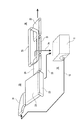
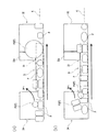
本実施形態に係る整列搬送装置は、使用済みとして回収されたトレイ、容器、蓋、パック等のプラスチックを一列に整列させて搬送するものであり、図1に示す如く、供給部10と、第1の整列部20と、第2の整列部30とに大別される。尚、詳しくは後述するが、本発明に係る整列搬送装置の「搬送手段」は、本実施形態においては、供給部10から第2の整列部30に亘って配置される形態で具現化され、本発明に係る整列搬送装置の「第1の整列手段」は、本実施形態においては、供給部10及び第1の整列部20のそれぞれに属する形態で具現化され、本発明に係る整列搬送装置の「第2の整列手段」は、本実施形態においては、第1の整列部20に属する形態で具現化され、本発明に係る整列搬送装置の「第3の整列手段」及び「挟持手段」は、本実施形態においては、第2の整列部30に属する形態で具現化され、本発明に係る整列搬送方法の「第一段階」は、本実施形態においては、供給部10及び第1の整列部20が行う機能として具現化され、本発明に係る整列搬送方法の「第二段階」は、本実施形態においては、第2の整列部30が行う機能として具現化される。
The aligning and conveying apparatus according to the present embodiment conveys plastics such as trays, containers, lids, and packs collected as used in an aligned manner. As shown in FIG. The
供給部10は、プラスチックを一時的に貯留するホッパー11と、該ホッパー11内のプラスチックを掻き出して搬送する第1のコンベア12とを備える。第1の整列部20は、供給部10の第1のコンベア12から送り出されたプラスチックを受け取って搬送する第2のコンベア21と、該第2のコンベア21から送り出されたプラスチックを受け取って搬送する第3のコンベア22と、該第3のコンベア22に並設された第4のコンベア23と、第3及び第4のコンベア22,23から送り出されたプラスチックを受け取って搬送する第5のコンベア24とを備える。第2の整列部30は、第5のコンベア24から送り出されたプラスチックを受け取って搬送する第6のコンベア31と、該第6のコンベア31から送り出されたプラスチックを受け取って搬送する第7のコンベア32と、第6のコンベア31に並設された第8のコンベア33とを備える。
The
そこで、プラスチックは、ホッパー11から第1のコンベア12によって搬送経路上に放出され、しかる後、第2のコンベア21、第3及び第4のコンベア22,23、第5のコンベア24、第6及び第8のコンベア31,33、及び第7のコンベア32を経由し、搬送経路に沿って一列に整列させた状態で下流側に設置される選別装置(図示しない)に搬送されるようになっている。尚、選別装置については、その構成等、周知であるため、説明を割愛する。
Therefore, the plastic is discharged from the
また、第1の整列部20は、適切に搬送処理できなかったプラスチックをホッパー11に返送するための返送経路としての第1の返送用コンベア25を備え、第2の整列部30は、同じく適切に搬送処理できなかったプラスチックをホッパー11に返送するための返送経路としての第2の返送用コンベア34を備え、第1の整列部20や第2の整列部30から脱落したプラスチックをホッパー11に戻すようにしている。尚、第1及び第2の返送用コンベア25,34は、途中にて合流してもよいし、それぞれ独立してホッパー11に接続されるようにしてもよい。
Further, the
第2のコンベア21は、平面視にて約90度の扇形を呈し、第1のコンベア21から送り出されたプラスチックを90度方向転換して第3のコンベア22に送り出す。第3のコンベア22は、幅方向に傾斜して配置され、第2のコンベア21から幅方向他方側に供給されたプラスチックは、幅方向一方側へと滑落するようになっている。第4のコンベア23は、第3のコンベア22の幅方向一方側に沿って配置される。しかも、第4のコンベア23は、幅方向一方側が第3のコンベア22の搬送面よりも上方に突出するよう配置され(そして、第3のコンベア22と直交するよう配置され)、第3のコンベア22を滑落してくるプラスチックは、第4のコンベア23で受け止められるようになっている。
The
第5のコンベア24は、平面視にて第3のコンベア22と同じ幅か、それよりも小さい幅のコンベアであり、第2のコンベア21と同様、水平に配置される。また、第5のコンベア24は、その幅方向一方側が第3のコンベア22の幅方向一方側と揃うように配置される。第6のコンベア31は、第5のコンベア24よりも幅狭のコンベアであり、その幅方向一方側が第5のコンベア24の幅方向一方側と揃うように配置され、幅方向において、プラスチックが並列して搬送されないようになっている。第7のコンベア32は、第6のコンベア31よりも幅広のコンベアであり、好ましくは、第5のコンベア24と同じ幅のコンベアであり、その幅方向一方側が第6のコンベア31の幅方向一方側と揃うように配置される。第6及び第7のコンベア31,32もまた、水平である。
The
第8のコンベア33は、第6のコンベア31と同程度の幅(第6のコンベア31の幅と同じか、それよりも僅かに広いか、それよりも僅かに狭い)のコンベアであり、やはり、水平に配置される。しかしながら、第8のコンベア33は、他のコンベアと異なり、無端回転する帯状搬送体が(ローラ間ピッチの約倍数よりも)長く、従って、下方が自重により弛んだ状態となっている。この弛み部は、第6のコンベア31のみならず、さらには、第5のコンベア24の下流側と第7のコンベア32の上流側に掛かる長さに形成される。
The
これら第1〜第8のコンベア12,21〜24,31〜33や、第1及び第2の返送用コンベア25,34は、公知のものを種々選択して採用できるが、本実施形態においては、第1、第4〜第7のコンベア12,23,24,31,32と、第1及び第2の返送用コンベア25,34は、ベルトコンベアであり、第2のコンベア21は、ベルトカーブコンベアであり、第3及び第8のコンベア22,33は、プラスチックモジュールコンベアである。
These first to
本実施形態に係る整列搬送装置の概略説明は以上のとおりであり、以下は、本実施形態に係る整列搬送方法を説明しつつ、各部の詳細説明を行うこととする。尚、以下に参酌される図において、処理対象となるプラスチックは、その外形を明確にすべく、適宜の箇所においてコンベアの外形線と隙間を有して記載しているが、プラスチックの配置態様が実際にそうであるか否かは技術的な意味合いから理解すべきである。 The outline description of the aligning and conveying apparatus according to the present embodiment is as described above, and the following is a detailed description of each part while explaining the aligning and conveying method according to the present embodiment. In the drawings referred to below, the plastic to be processed is described with a conveyor outline and a gap at an appropriate place in order to clarify the outer shape, but the plastic arrangement mode is described. Whether this is the case or not should be understood from a technical point of view.
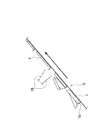
図2に示す如く、ホッパー11から排出されたプラスチックPは、第1のコンベア12によって上方に運ばれる。第1のコンベア12は、ホッパー11から斜め上方に傾斜(本実施形態においては、約45度)して配置されており、所定間隔で桟12aが設けられている。従って、この桟12aに引っ掛かったプラスチックPは桟12aによって斜め上方に搬送され、また、桟12aに引っ掛からないプラスチックPは滑り落ちることでならされ、搬送量が定量化される。
As shown in FIG. 2, the plastic P discharged from the
また、桟12aが設けられた第1のコンベア12の上面側には、揺動自在な掻き落とし体12bが設けられ、第1のコンベア12上のプラスチックPをならすことにより、上下に重なった状態にあるプラスチックP,Pのうち、上側のプラスチックPに力を作用させて重なりを解消させる。この意味で、桟12a及び掻き落とし体12bは、ホッパー11内に投入されたプラスチックの定量切り出し手段として機能すると共に、本発明に係る「上下に重なった状態にあるプラスチックのうち、上側のプラスチックに力を作用させて重なりを解消させる第1の整列手段」として機能する。
Further, a
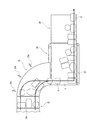
次に、図3に示す如く、プラスチックPは、第1のコンベア12から第2のコンベア21に送り出される。第2のコンベア21は、大径側の適宜箇所にエアーブロー手段21aが配置されており、該エアーブロー手段21a,…から中心方向に噴射されるエアーによって、プラスチックPは、第2コンベア21上の小径側に寄せられる。この意味で、エアーブロー手段12a,…は、本発明に係る「プラスチックを搬送経路の幅方向一方側に寄せる第2の整列手段」として機能する。
Next, as shown in FIG. 3, the plastic P is sent from the
そして、プラスチックPは、第2のコンベア21から第3のコンベア22に送り出されれ、第3のコンベア22では、第4のコンベア23で受け止められるまで、あるいは第4のコンベア23で既に受け止められたプラスチックPに当たるまで、滑落し、その結果、第3のコンベア22の下端側に寄せられる。この意味で、傾斜して配置された第3のコンベア22及びその下端に配置された第4のコンベア23は、本発明に係る「プラスチックを搬送経路の幅方向一方側に寄せる第2の整列手段」として機能する。
Then, the plastic P is sent out from the
ところで、なぜ、第2のコンベア21と第3のコンベア22の両方に対し、第2の整列手段を講じなければならないかということであるが、例えば、第2のコンベア21に第2の整列手段がないとすると、第2のコンベア21から第3のコンベア22に移行するプラスチックPは、第2のコンベア21の幅全体で行われることになり、そうなると、第2のコンベア21の小径側から第3のコンベア22の上流側に滑落し且つ第3のコンベア22によって下流側に搬送されるプラスチックPの上に、第2のコンベア21の大径側からプラスチックPが滑落してきて幅方向に重なってしまう頻度が増えてしまうため、まずは、これを無くしたいということがある。もう一つは、第2のコンベア21からのプラスチックPをできるだけ第3のコンベア22の上流側に集中させて供給し、第3のコンベア22におけるプラスチックPに対する作用を最大限にさせたいということがある。
By the way, the reason why the second alignment means must be provided for both the
次に、プラスチックPは、第3のコンベア22から第5のコンベア24に送り出される。第3のコンベア22は、傾斜しているのに対し、第5のコンベア24は、水平であるため、第3及び第5のコンベア22,24のそれぞれ幅方向一方側から他方側に行くに従って、第3のコンベア22の下流端と第5のコンベア24の上流端との間隔は広がるが、これによる影響は少なく、従って、プラスチックPは、第3のコンベア22上に置かれた態様のままで第5のコンベア24に移行される。
Next, the plastic P is sent out from the
このように、プラスチックPは、第2のコンベア21で90度方向転換され、また、第3のコンベア22でまた90度方向転換され、しかる後、第3のコンベア22から第5のコンベア24にかけては(さらには、それ以降も)、直線的に搬送される。実線Lは、プラスチックPの搬送軌跡を示す。尚、第4のコンベア23は、第3のコンベア22と同速度で無端回転するようになっているが、両者に速度差を持たせてもよい。
In this manner, the plastic P is turned 90 degrees on the
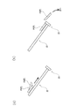
ここで、図4に示す如く、第3のコンベア22を滑落するプラスチックP1は、第4のコンベア23なり、それに受け止められたプラスチックPに受け止められる際、幅方向への慣性力が働く。しかしながら、第4のコンベア23なり、それに受け止められたプラスチックPに受け止められることで、それ以上の第3のコンベア22の幅方向への移動は制止されるようになっている。しかしながら、上に重なった状態にあるプラスチックP2は、その移動を制止する手段は何もなく、従って、そのまま慣性力により搬送経路から脱落するようになっている。この意味で、傾斜して配置された第3のコンベア22及びその下端に配置された第4のコンベア23は、本発明に係る「上下に重なった状態にあるプラスチックのうち、上側のプラスチックに力を作用させて重なりを解消させる第1の整列手段」として機能する。尚、第4のコンベア23を乗り越えて脱落したプラスチックP2は、第1の返送用コンベア25に回収され、ホッパー11に返送される。
Here, as shown in FIG. 4, the plastic P1 sliding down the
また、図5に示す如く、プラスチックPが例えば容器と蓋が一体化したものである場合は、プラスチックPが第4のコンベア23に跨った状態となってそのまま第5のコンベア24に向けて搬送されることもある。しかしながら、これでは、整列性に支障を来すため、第3のコンベア22の下流側、あるいは第5のコンベア24の上流側には、エアーブロー手段22aが設けられ、該エアーブロー手段22aから噴射されるエアーによってプラスチックPを搬送経路外へ吹き飛ばすようにしている。このプラスチックPもまた、第1の返送用コンベア25に回収され、ホッパー11に返送される。
Further, as shown in FIG. 5, when the plastic P is, for example, a container and a lid integrated, the plastic P straddles the
次に、図6に示す如く、プラスチックPは、第5のコンベア24から第6のコンベア31に送り出される。しかしながら、第6のコンベア31は、幅が狭くなっているため、第5のコンベア24の幅方向一方側に寄せられたプラスチックPしか乗らない。従って、それ以外のプラスチックP1,P3は、第5のコンベア24の下流端から脱落するようになっている。この意味で、幅が狭く設定された第6のコンベア31は、本発明に係る「搬送経路の幅方向一方側に一列に整列されなかったプラスチックを搬送経路から脱落させる第3の整列手段」として機能する。尚、第6のコンベア31に乗らずに脱落したプラスチックP1,3は、第2の返送用コンベア34に回収され、ホッパー11に返送される。
Next, as shown in FIG. 6, the plastic P is sent from the
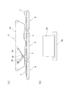
但し、プラスチックP2のように、第6のコンベア31の幅よりも十分に大きく、その重心が第6のコンベア31からはみ出してしまうような場合、何もなければ、プラスチックP2は、プラスチックP1,3と同様、脱落してしまうが、そのようにはならず、第8のコンベア33が第6のコンベア31とでプラスチックP2を挟持して搬送するため、プラスチックP2は、整列の対象として維持される。この意味で、第6のコンベア31及び第8のコンベア33は、本発明に係る「搬送経路の幅方向一方側に一列に整列されたプラスチックが搬送経路から脱落しないよう、該プラスチックを上方から押さえ付けて搬送手段とで挟持する挟持手段」として機能する。
However, if the width of the
尚、第6のコンベア31の幅方向他方側からはみ出す大きさのプラスチックPであって、そのはみ出す部分が例えば容器と蓋が一体化したプラスチックの蓋であるような場合、この蓋は第6のコンベア31によって下方支持されないために垂れ下がり気味となり、そのままでは、第7のコンベア32に移行しようとする際、第7のコンベア32の上流端に当たってしまい、その結果、プラスチックP1,P3と同様、搬送経路から脱落してしまう事態が起こり得る。そこで、本実施形態においては、第6のコンベア31の下流端に並列するようにして、第7のコンベア32の上流端と連絡するガイド板32aを設けている。該ガイド板32aは、下流端が第7のコンベア32の上流端に近接し、上流側ほど下方に傾斜する傾斜板であり、第6のコンベア31の側方からはみ出して垂れ下がったプラスチックPは、その垂れ下がった部分がガイド板32aによって持ち上げられ、水平姿勢に修正されるため、支障なく第7のコンベア32に移行させることができる。
In the case where the plastic P has a size that protrudes from the other side in the width direction of the
このように、プラスチックPは、第5のコンベア24から第6のコンベア31に移行する際、搬送経路の幅が狭くなることで、不適切な配置のものが選別され、搬送経路に沿って一列に整列されて搬送され、下流側の選別装置に送り込まれる。図中の一点鎖線Kは、選別装置における材質特定センサの読み取りラインを示すが、これによれば、搬送経路の幅方向一方側に一列に整列されたプラスチックPは、大きさ、形状の如何を問わず、すべからく、適切に特定されていくことになる。
As described above, when the plastic P shifts from the
それでは、プラスチックP4のように、搬送経路の幅方向一方側に一列に整列されるわけではなく、幅方向に重なって搬送されるが、しかしながら、不安定な状態ながらも第8のコンベア33によって上方から押さえ付けられるために、搬送経路から脱落しにくくなっているようなものは、どうなるかという疑問が残る。
Then, unlike plastic P4, it is not aligned in a line on one side in the width direction of the transport path, but is transported in the width direction. However, although it is unstable, it is moved upward by the
これについては、(図6(b)の側面図である)図7に示す如く、第8のコンベア33の特殊な構造によって解決がなされる。即ち、第8のコンベア33は、帯状搬送体33aの弛み量が十分に大きいために、各プラスチックPの高低に応じて形状が追従するようになっているばかりでなく、この帯状搬送体33aの内面の湾曲形状に追従して上下動する可動体としてのローラ(ダンサーローラ)33bが設けられている。該ローラ33bは、一端が装置側に固定された揺動体33cであって、弾性体33dにより上方向に引っ張り弾性力が付勢される揺動体33cの他端に回転自在に取り付けられ、帯状搬送体33aの内面の湾曲形状に追従するのであるが、弾性体33dの作用により、若干のタイムラグが発生するようになっている。即ち、ローラ33bは、帯状搬送体33aの内面の湾曲形状にリニアに追従することができず、帯状搬送体33aの内面に適宜接触し、帯状搬送体33aに振動を与える作用を生じさせる。これにより、不安定な状態で挟持されるプラスチックP4は、ふるい落とされることとなり、その結果、邪魔なものが排除されて、整列性は担保されるのである。
This is solved by a special structure of the
尚、帯状搬送体33aは、弛みを設けている分、蛇行したりして、ローラから外れる懸念があるが、その内面の両端には、隆起部が設けられ、左右の隆起部間にローラ33bが配置され、該ローラ33bによって弛み部の蛇行が規制されるようになっている。
Although the belt-
以上、本実施形態に係る整列搬送装置及び整列搬送方法によれば、不定型であり、大きさが不均一なために整列搬送性が劣るプラスチックであっても、確実に一列に整列させることができ、その結果、下流側に設置される選別装置にて、プラスチックの材質の特定処理及びそのプラスチックの選別処理を効果的に行うことができるようになる。 As described above, according to the aligning and conveying apparatus and the aligning and conveying method according to the present embodiment, even if the plastic is indeterminate and the size and the size are not uniform, the aligning and conveying property can be surely aligned in a line. As a result, it is possible to effectively perform the plastic material specifying process and the plastic sorting process in the sorting apparatus installed on the downstream side.
尚、本発明は、上記実施形態に限定されるものではなく、本発明の要旨を逸脱しない範囲で種々の変更が可能である。 In addition, this invention is not limited to the said embodiment, A various change is possible in the range which does not deviate from the summary of this invention.
例えば、上記実施形態においては、第3のコンベア22と同期して第4のコンベア23が走行するようになっているが、第3のコンベア22の幅方向一方側に並設されるガイド体としては、第4のコンベア23の代わりに、第3のコンベア22に沿って長尺な板材であってもよい。この場合、板材は、摩擦抵抗の少なく、スベリ性の良好な材質のものや、そのようなコーティングを施したものが好ましい。
For example, in the said embodiment, although the
また、上記実施形態においては、第6のコンベア31と同期して第8のコンベア33が走行するようになっているが、両者に速度差を持たせてもよい。例えば、第8のコンベア33を第6のコンベア31よりも速く走行させることで、ダンサーローラ33bと同様、不必要に挟持されるプラスチックをふるい落とす効果が期待できる。この点、かかる構成もダンサーローラ33bと同様、本発明に係る「振動付与手段」となる。
Moreover, in the said embodiment, although the
また、上記実施形態においては、ダンサーローラ33bは、揺動自在な支持体によって支持されて可動に構成され、従って、ダンサーローラ33bは、円弧状に動くが、それは、単なる上下動であってもよい。また、ダンサーローラ33bの数も一つに限定されず、適宜間隔を有して複数設けるようにしてもよい。
In the above-described embodiment, the
また、上記実施形態においては、第2のコンベア21として、カーブベルトコンベアを採用したが、例えば、装置のレイアウト等の事情によって搬送の向きを変える必要がなければ、第3のコンベア22や第5のコンベア24のようにストレートなコンベアであってもよい。
Moreover, in the said embodiment, although the curve belt conveyor was employ | adopted as the
また、上記実施形態においては、幅方向に傾斜して配置される第3のコンベア22と、該第3のコンベア22の幅方向一方側であって該第3のコンベア22に沿って配置され、該第3のコンベア22の搬送面よりも所定高さで上方に突出するガイド体(第4のコンベア23)とで本発明に係る第2の整列手段を構成するようにしているが、これに限定されず、代わりに、例えば水平に配置された片寄せコンベアであってもよい。
Moreover, in the said embodiment, it is arrange | positioned along the
10…供給部、11…ホッパー、12…第1のコンベア、12a…桟、12b…掻き落とし体、20…第1の整列部、21…第2のコンベア、21a…エアーブロー手段、22…第3のコンベア、22a…エアーブロー手段、23…第4のコンベア、24…第5のコンベア、25…第1の返送用コンベア、30…第2の整列部、31…第6のコンベア、32…第7のコンベア、32a…ガイド板(ガイド体)、33…第8のコンベア、33a…帯状搬送体、33b…ローラ(可動体)、33c…揺動体、33d…弾性体、34…第2の返送用コンベア、P…プラスチック
DESCRIPTION OF
Claims (7)
Priority Applications (1)
| Application Number | Priority Date | Filing Date | Title |
|---|---|---|---|
| JP2008034469A JP5346474B2 (en) | 2008-02-15 | 2008-02-15 | Alignment transport device |
Applications Claiming Priority (1)
| Application Number | Priority Date | Filing Date | Title |
|---|---|---|---|
| JP2008034469A JP5346474B2 (en) | 2008-02-15 | 2008-02-15 | Alignment transport device |
Publications (2)
| Publication Number | Publication Date |
|---|---|
| JP2009190856A true JP2009190856A (en) | 2009-08-27 |
| JP5346474B2 JP5346474B2 (en) | 2013-11-20 |
Family
ID=41073217
Family Applications (1)
| Application Number | Title | Priority Date | Filing Date |
|---|---|---|---|
| JP2008034469A Active JP5346474B2 (en) | 2008-02-15 | 2008-02-15 | Alignment transport device |
Country Status (1)
| Country | Link |
|---|---|
| JP (1) | JP5346474B2 (en) |
Cited By (2)
| Publication number | Priority date | Publication date | Assignee | Title |
|---|---|---|---|---|
| JP2018172185A (en) * | 2017-03-31 | 2018-11-08 | マツダエース株式会社 | Food arrangement apparatus |
| KR20230040653A (en) * | 2021-09-16 | 2023-03-23 | 김기삼 | Pouch alignment apparatus |
Citations (3)
| Publication number | Priority date | Publication date | Assignee | Title |
|---|---|---|---|---|
| JPH08282825A (en) * | 1995-04-14 | 1996-10-29 | Yanmar Agricult Equip Co Ltd | Conveying device for crop grading device |
| JP2000007141A (en) * | 1998-06-25 | 2000-01-11 | Ishii Ind Co Ltd | Article supplying device |
| JP2000308855A (en) * | 1999-02-26 | 2000-11-07 | Nkk Corp | Sorting device for waste plastic |
-
2008
- 2008-02-15 JP JP2008034469A patent/JP5346474B2/en active Active
Patent Citations (3)
| Publication number | Priority date | Publication date | Assignee | Title |
|---|---|---|---|---|
| JPH08282825A (en) * | 1995-04-14 | 1996-10-29 | Yanmar Agricult Equip Co Ltd | Conveying device for crop grading device |
| JP2000007141A (en) * | 1998-06-25 | 2000-01-11 | Ishii Ind Co Ltd | Article supplying device |
| JP2000308855A (en) * | 1999-02-26 | 2000-11-07 | Nkk Corp | Sorting device for waste plastic |
Cited By (3)
| Publication number | Priority date | Publication date | Assignee | Title |
|---|---|---|---|---|
| JP2018172185A (en) * | 2017-03-31 | 2018-11-08 | マツダエース株式会社 | Food arrangement apparatus |
| KR20230040653A (en) * | 2021-09-16 | 2023-03-23 | 김기삼 | Pouch alignment apparatus |
| KR102606511B1 (en) * | 2021-09-16 | 2023-11-24 | 김기삼 | Pouch alignment apparatus |
Also Published As
| Publication number | Publication date |
|---|---|
| JP5346474B2 (en) | 2013-11-20 |
Similar Documents
| Publication | Publication Date | Title |
|---|---|---|
| JP2016539883A (en) | Singulator conveyor system for large bags of hard and small parcels | |
| JP5728741B2 (en) | Cartoner | |
| JPH09301310A (en) | Boxing device | |
| JP5878727B2 (en) | Packaging device | |
| JP5346474B2 (en) | Alignment transport device | |
| JP2019058220A (en) | Tablet printing device | |
| JP2007230751A (en) | Grouping device | |
| JP2008013227A (en) | Transfer device and boxing apparatus equipped with the same | |
| JP5819101B2 (en) | Article separation and supply device and transport system using the same | |
| JP2009233581A (en) | Sorting device | |
| JP5785693B2 (en) | Column increasing device | |
| JP2008155962A (en) | Transfer device for items to be transferred and transferring system for items to be transferred | |
| JP6038624B2 (en) | Weight sorter | |
| JP6143564B2 (en) | Article sorting equipment | |
| JP4773752B2 (en) | Bar-shaped article stacking device | |
| JP6782883B2 (en) | Transport equipment and inspection equipment | |
| JP2006016068A (en) | Packaging method and packaging apparatus for sliced bread | |
| TWI787738B (en) | Transporting device and transporting method | |
| JP2020062150A (en) | Conveying device and conveyed article processing apparatus with the same | |
| JP6173051B2 (en) | Article sorting equipment | |
| JPH06227650A (en) | Transfer device for spherical or ellipse article | |
| JPH09208035A (en) | Supply equipment of collected bottle | |
| JP2564261Y2 (en) | Package supply device | |
| JP4684615B2 (en) | Product accumulation / transfer equipment | |
| JP2004196466A (en) | Feeding device for long article |
Legal Events
| Date | Code | Title | Description |
|---|---|---|---|
| A621 | Written request for application examination |
Free format text: JAPANESE INTERMEDIATE CODE: A621 Effective date: 20101208 |
|
| A977 | Report on retrieval |
Free format text: JAPANESE INTERMEDIATE CODE: A971007 Effective date: 20121109 |
|
| A131 | Notification of reasons for refusal |
Free format text: JAPANESE INTERMEDIATE CODE: A131 Effective date: 20121130 |
|
| A131 | Notification of reasons for refusal |
Free format text: JAPANESE INTERMEDIATE CODE: A131 Effective date: 20130614 |
|
| A521 | Request for written amendment filed |
Free format text: JAPANESE INTERMEDIATE CODE: A523 Effective date: 20130702 |
|
| TRDD | Decision of grant or rejection written | ||
| A01 | Written decision to grant a patent or to grant a registration (utility model) |
Free format text: JAPANESE INTERMEDIATE CODE: A01 Effective date: 20130802 |
|
| A61 | First payment of annual fees (during grant procedure) |
Free format text: JAPANESE INTERMEDIATE CODE: A61 Effective date: 20130819 |
|
| R150 | Certificate of patent or registration of utility model |
Ref document number: 5346474 Country of ref document: JP Free format text: JAPANESE INTERMEDIATE CODE: R150 Free format text: JAPANESE INTERMEDIATE CODE: R150 |
|
| S531 | Written request for registration of change of domicile |
Free format text: JAPANESE INTERMEDIATE CODE: R313531 |
|
| R350 | Written notification of registration of transfer |
Free format text: JAPANESE INTERMEDIATE CODE: R350 |
|
| R250 | Receipt of annual fees |
Free format text: JAPANESE INTERMEDIATE CODE: R250 |
|
| R250 | Receipt of annual fees |
Free format text: JAPANESE INTERMEDIATE CODE: R250 |
|
| R250 | Receipt of annual fees |
Free format text: JAPANESE INTERMEDIATE CODE: R250 |