JP2009166301A - Strand forming method and forming apparatus - Google Patents
Strand forming method and forming apparatus Download PDFInfo
- Publication number
- JP2009166301A JP2009166301A JP2008005245A JP2008005245A JP2009166301A JP 2009166301 A JP2009166301 A JP 2009166301A JP 2008005245 A JP2008005245 A JP 2008005245A JP 2008005245 A JP2008005245 A JP 2008005245A JP 2009166301 A JP2009166301 A JP 2009166301A
- Authority
- JP
- Japan
- Prior art keywords
- die
- hole
- gas
- strand
- inert gas
- Prior art date
- Legal status (The legal status is an assumption and is not a legal conclusion. Google has not performed a legal analysis and makes no representation as to the accuracy of the status listed.)
- Abandoned
Links
- 238000000034 method Methods 0.000 title claims abstract description 17
- 239000007789 gas Substances 0.000 claims abstract description 45
- 238000010438 heat treatment Methods 0.000 claims abstract description 25
- 239000007921 spray Substances 0.000 claims abstract description 11
- 239000011261 inert gas Substances 0.000 claims description 35
- 238000005507 spraying Methods 0.000 claims description 13
- 238000011144 upstream manufacturing Methods 0.000 claims description 2
- IJGRMHOSHXDMSA-UHFFFAOYSA-N Atomic nitrogen Chemical compound N#N IJGRMHOSHXDMSA-UHFFFAOYSA-N 0.000 abstract description 18
- 229910001873 dinitrogen Inorganic materials 0.000 abstract description 18
- 239000008188 pellet Substances 0.000 abstract description 10
- 238000007254 oxidation reaction Methods 0.000 abstract description 5
- 230000003647 oxidation Effects 0.000 abstract description 4
- 238000002845 discoloration Methods 0.000 abstract description 3
- 238000010586 diagram Methods 0.000 description 6
- 238000012423 maintenance Methods 0.000 description 4
- QVGXLLKOCUKJST-UHFFFAOYSA-N atomic oxygen Chemical compound [O] QVGXLLKOCUKJST-UHFFFAOYSA-N 0.000 description 3
- 238000000465 moulding Methods 0.000 description 3
- 239000001301 oxygen Substances 0.000 description 3
- 229910052760 oxygen Inorganic materials 0.000 description 3
- 230000000704 physical effect Effects 0.000 description 3
- 150000001875 compounds Chemical class 0.000 description 2
- 230000006866 deterioration Effects 0.000 description 2
- 230000000694 effects Effects 0.000 description 2
- 238000004898 kneading Methods 0.000 description 2
- 239000000565 sealant Substances 0.000 description 2
- 238000007493 shaping process Methods 0.000 description 2
- 238000007711 solidification Methods 0.000 description 2
- 230000008023 solidification Effects 0.000 description 2
- 230000032683 aging Effects 0.000 description 1
- 238000011109 contamination Methods 0.000 description 1
- 238000005520 cutting process Methods 0.000 description 1
- 238000001125 extrusion Methods 0.000 description 1
- 238000004519 manufacturing process Methods 0.000 description 1
- 239000000463 material Substances 0.000 description 1
- 230000002265 prevention Effects 0.000 description 1
Images

Classifications
-
- B—PERFORMING OPERATIONS; TRANSPORTING
- B29—WORKING OF PLASTICS; WORKING OF SUBSTANCES IN A PLASTIC STATE IN GENERAL
- B29B—PREPARATION OR PRETREATMENT OF THE MATERIAL TO BE SHAPED; MAKING GRANULES OR PREFORMS; RECOVERY OF PLASTICS OR OTHER CONSTITUENTS OF WASTE MATERIAL CONTAINING PLASTICS
- B29B9/00—Making granules
- B29B9/02—Making granules by dividing preformed material
- B29B9/06—Making granules by dividing preformed material in the form of filamentary material, e.g. combined with extrusion
-
- B—PERFORMING OPERATIONS; TRANSPORTING
- B29—WORKING OF PLASTICS; WORKING OF SUBSTANCES IN A PLASTIC STATE IN GENERAL
- B29C—SHAPING OR JOINING OF PLASTICS; SHAPING OF MATERIAL IN A PLASTIC STATE, NOT OTHERWISE PROVIDED FOR; AFTER-TREATMENT OF THE SHAPED PRODUCTS, e.g. REPAIRING
- B29C48/00—Extrusion moulding, i.e. expressing the moulding material through a die or nozzle which imparts the desired form; Apparatus therefor
- B29C48/03—Extrusion moulding, i.e. expressing the moulding material through a die or nozzle which imparts the desired form; Apparatus therefor characterised by the shape of the extruded material at extrusion
- B29C48/05—Filamentary, e.g. strands
-
- B—PERFORMING OPERATIONS; TRANSPORTING
- B29—WORKING OF PLASTICS; WORKING OF SUBSTANCES IN A PLASTIC STATE IN GENERAL
- B29C—SHAPING OR JOINING OF PLASTICS; SHAPING OF MATERIAL IN A PLASTIC STATE, NOT OTHERWISE PROVIDED FOR; AFTER-TREATMENT OF THE SHAPED PRODUCTS, e.g. REPAIRING
- B29C48/00—Extrusion moulding, i.e. expressing the moulding material through a die or nozzle which imparts the desired form; Apparatus therefor
- B29C48/03—Extrusion moulding, i.e. expressing the moulding material through a die or nozzle which imparts the desired form; Apparatus therefor characterised by the shape of the extruded material at extrusion
- B29C48/07—Flat, e.g. panels
- B29C48/08—Flat, e.g. panels flexible, e.g. films
-
- B—PERFORMING OPERATIONS; TRANSPORTING
- B29—WORKING OF PLASTICS; WORKING OF SUBSTANCES IN A PLASTIC STATE IN GENERAL
- B29C—SHAPING OR JOINING OF PLASTICS; SHAPING OF MATERIAL IN A PLASTIC STATE, NOT OTHERWISE PROVIDED FOR; AFTER-TREATMENT OF THE SHAPED PRODUCTS, e.g. REPAIRING
- B29C48/00—Extrusion moulding, i.e. expressing the moulding material through a die or nozzle which imparts the desired form; Apparatus therefor
- B29C48/25—Component parts, details or accessories; Auxiliary operations
- B29C48/27—Cleaning; Purging; Avoiding contamination
- B29C48/272—Cleaning; Purging; Avoiding contamination of dies
-
- B—PERFORMING OPERATIONS; TRANSPORTING
- B29—WORKING OF PLASTICS; WORKING OF SUBSTANCES IN A PLASTIC STATE IN GENERAL
- B29C—SHAPING OR JOINING OF PLASTICS; SHAPING OF MATERIAL IN A PLASTIC STATE, NOT OTHERWISE PROVIDED FOR; AFTER-TREATMENT OF THE SHAPED PRODUCTS, e.g. REPAIRING
- B29C48/00—Extrusion moulding, i.e. expressing the moulding material through a die or nozzle which imparts the desired form; Apparatus therefor
- B29C48/25—Component parts, details or accessories; Auxiliary operations
- B29C48/30—Extrusion nozzles or dies
- B29C48/345—Extrusion nozzles comprising two or more adjacently arranged ports, for simultaneously extruding multiple strands, e.g. for pelletising
-
- B—PERFORMING OPERATIONS; TRANSPORTING
- B29—WORKING OF PLASTICS; WORKING OF SUBSTANCES IN A PLASTIC STATE IN GENERAL
- B29C—SHAPING OR JOINING OF PLASTICS; SHAPING OF MATERIAL IN A PLASTIC STATE, NOT OTHERWISE PROVIDED FOR; AFTER-TREATMENT OF THE SHAPED PRODUCTS, e.g. REPAIRING
- B29C48/00—Extrusion moulding, i.e. expressing the moulding material through a die or nozzle which imparts the desired form; Apparatus therefor
- B29C48/25—Component parts, details or accessories; Auxiliary operations
- B29C48/78—Thermal treatment of the extrusion moulding material or of preformed parts or layers, e.g. by heating or cooling
- B29C48/86—Thermal treatment of the extrusion moulding material or of preformed parts or layers, e.g. by heating or cooling at the nozzle zone
- B29C48/865—Heating
-
- B—PERFORMING OPERATIONS; TRANSPORTING
- B29—WORKING OF PLASTICS; WORKING OF SUBSTANCES IN A PLASTIC STATE IN GENERAL
- B29C—SHAPING OR JOINING OF PLASTICS; SHAPING OF MATERIAL IN A PLASTIC STATE, NOT OTHERWISE PROVIDED FOR; AFTER-TREATMENT OF THE SHAPED PRODUCTS, e.g. REPAIRING
- B29C48/00—Extrusion moulding, i.e. expressing the moulding material through a die or nozzle which imparts the desired form; Apparatus therefor
- B29C48/25—Component parts, details or accessories; Auxiliary operations
- B29C48/88—Thermal treatment of the stream of extruded material, e.g. cooling
- B29C48/91—Heating, e.g. for cross linking
-
- B—PERFORMING OPERATIONS; TRANSPORTING
- B29—WORKING OF PLASTICS; WORKING OF SUBSTANCES IN A PLASTIC STATE IN GENERAL
- B29C—SHAPING OR JOINING OF PLASTICS; SHAPING OF MATERIAL IN A PLASTIC STATE, NOT OTHERWISE PROVIDED FOR; AFTER-TREATMENT OF THE SHAPED PRODUCTS, e.g. REPAIRING
- B29C2791/00—Shaping characteristics in general
- B29C2791/004—Shaping under special conditions
- B29C2791/005—Using a particular environment, e.g. sterile fluids other than air
-
- B—PERFORMING OPERATIONS; TRANSPORTING
- B29—WORKING OF PLASTICS; WORKING OF SUBSTANCES IN A PLASTIC STATE IN GENERAL
- B29C—SHAPING OR JOINING OF PLASTICS; SHAPING OF MATERIAL IN A PLASTIC STATE, NOT OTHERWISE PROVIDED FOR; AFTER-TREATMENT OF THE SHAPED PRODUCTS, e.g. REPAIRING
- B29C48/00—Extrusion moulding, i.e. expressing the moulding material through a die or nozzle which imparts the desired form; Apparatus therefor
- B29C48/03—Extrusion moulding, i.e. expressing the moulding material through a die or nozzle which imparts the desired form; Apparatus therefor characterised by the shape of the extruded material at extrusion
- B29C48/04—Particle-shaped
Landscapes
- Engineering & Computer Science (AREA)
- Mechanical Engineering (AREA)
- Physics & Mathematics (AREA)
- Thermal Sciences (AREA)
- Manufacturing & Machinery (AREA)
- Processing And Handling Of Plastics And Other Materials For Molding In General (AREA)
- Spinning Methods And Devices For Manufacturing Artificial Fibers (AREA)
- Extrusion Moulding Of Plastics Or The Like (AREA)
Abstract
【課題】装置構成の簡素化を図ったとしてもペレットの品質を十分に確保することが可能なストランド成形方法及び成形装置を提供する。
【解決手段】常温の窒素ガスを加熱装置にて高温状態にするとともに、風量調節装置を通過させると、風量と温度とが調節された高温の窒素ガスになる。そして、これを一対のガス噴霧器5に送った後に、ダイス1の各穴3に向けて噴霧する。この方法でダイス1の各穴3の周辺を高温の窒素ガスで充満させ、メヤニ23の酸化による変色を防止しつつ各穴3からストランド2を押し出し成形する。穴3の周辺に高温の窒素ガスが充満していることから、メヤニ23は酸化することなく、また、メヤニ23は固化することもない。
【選択図】図5The present invention provides a strand forming method and a forming apparatus capable of sufficiently ensuring the quality of pellets even if the apparatus configuration is simplified.
When normal temperature nitrogen gas is brought into a high temperature state by a heating device and passed through an air flow rate adjusting device, the flow rate and temperature of the nitrogen gas become high temperature. And after sending this to a pair of gas sprayer 5, it sprays toward each hole 3 of the die | dye 1. FIG. By this method, the periphery of each hole 3 of the die 1 is filled with high-temperature nitrogen gas, and the strand 2 is extruded from each hole 3 while preventing discoloration due to oxidation of the mains 23. Since the periphery of the hole 3 is filled with high-temperature nitrogen gas, the main 23 is not oxidized, and the main 23 is not solidified.
[Selection] Figure 5
Description
本発明は、混練機から押し出されるストランドの成形方法と、混練機を含んで構成されるストランド成形装置とに関する。 The present invention relates to a method for forming a strand extruded from a kneader and a strand forming apparatus including the kneader.
混練機のシリンダヘッドにノズル部を介して装着されたダイの穴からストランドを押し出し、この押し出しと同時に回転刃カッターで所定の長さにカットしてペレット化し、これによりペレットを製造する技術が下記特許文献1に開示されている。この開示技術によれば、ダイには、ストランドを押し出す側にケーシングが一体に取り付けられている。ケーシングは、この内部空間に不活性ガスを充満させることができるように形成されている。
ところで、上記従来技術にあっては、ペレット化されたものが不活性ガスの充満したケーシングを通過するようになっていることから、ケーシングを出るまでは空気中の酸素に触れることのない成形方法及び装置を採用していることになる。物性低下の防止に配慮した成形方法及び装置であるといえるが、不活性ガスを充満させるためのケーシングを備えたり、このケーシングをダイに一体化させたりする必要があることから、大がかりな装置や大きなスペースが必要になってしまうという問題点を有している。また、ケーシングの存在によってダイの交換や装置メンテナンス作業が困難になってしまうという問題点も有している。 By the way, in the said prior art, since the pelletized thing passes through the casing filled with the inert gas, it does not touch oxygen in air until it leaves the casing. And the device is adopted. Although it can be said that it is a molding method and apparatus in consideration of prevention of deterioration of physical properties, it is necessary to provide a casing for filling with an inert gas or to integrate this casing into a die. There is a problem that a large space is required. In addition, there is a problem that die replacement and device maintenance work become difficult due to the presence of the casing.
尚、上記問題点の対策としてケーシングを備えず、また、不活性ガスを充満させないようにすると、ダイの穴の周囲に生じたメヤニが酸化して変色し、これがストランドに付着してしまうと、物性低下や異物混入につながる恐れがあると本願発明者は懸念している。 In addition, if the casing is not provided as a countermeasure against the above-mentioned problems and the inert gas is not filled, the scum generated around the hole in the die is oxidized and discolored, and this adheres to the strand. The inventor of the present application is concerned that there is a risk of deterioration of physical properties or contamination with foreign matter.
この他、本願発明者はメヤニ発生を防止するために、ダイの材質改善やダイの穴の形状変更をすることによっての流動性向上をねらった改善方法に関して、ダイの老朽化、ダイの穴の形状変化により恒久的な対策とならないことを突き止めている。 In addition, the inventor of the present application relates to an improvement method aiming to improve fluidity by improving the material of the die and changing the shape of the die hole in order to prevent occurrence of a sag, the aging of the die, the die hole It has been determined that the shape change does not become a permanent measure.
本発明は、上述した事情に鑑みてなされたもので、装置構成の簡素化を図ったとしてもペレットの品質を十分に確保することが可能なストランド成形方法及び成形装置を提供することを課題とする。 The present invention has been made in view of the above-described circumstances, and it is an object to provide a strand forming method and a forming apparatus capable of sufficiently ensuring the quality of pellets even if the apparatus configuration is simplified. To do.
上記課題を解決するためになされた請求項1記載の本発明のストランド成形方法は、ダイ又はダイスの穴に向けて不活性ガスを噴霧しつつ前記穴からストランドを押出成形することを特徴としている。
The strand forming method of the present invention according to
このような特徴を有する本発明によれば、ダイ又はダイスの穴の周辺が不活性ガスで充満する。メヤニが発生しても、このメヤニが発生した部分が不活性ガスの噴霧によって空気中の酸素に触れることのない状態になる。 According to the present invention having such characteristics, the periphery of the die or the hole of the die is filled with the inert gas. Even if the scum is generated, the part where the sag is generated does not come into contact with oxygen in the air by spraying the inert gas.
請求項2記載の本発明のストランド成形方法は、請求項1に記載のストランド成形方法において、前記不活性ガスを加熱装置で加熱するとともに風量調節装置で風量を調節しつつ噴霧することを特徴としている。
The strand forming method of the present invention according to
このような特徴を有する本発明によれば、メヤニが発生しても、加熱され風量の調節された不活性ガスによって、ダイ又はダイスの穴に生じるメヤニの固化が防止される。 According to the present invention having such a feature, even when a scum is generated, the sag of the scum generated in the die or the hole of the die is prevented by the heated inert gas whose air volume is adjusted.
上記課題を解決するためになされた請求項3記載の本発明のストランド成形装置は、ダイ又はダイスの穴に向けて不活性ガスを噴霧するガス噴霧器を前記穴の近傍に備えることを特徴としている。
The strand forming apparatus of the present invention according to
このような特徴を有する本発明によれば、メヤニが発生してもこのメヤニが発生した部分がガス噴霧器から噴霧される不活性ガスによって空気中の酸素に触れることのない状態になる。本発明によれば、ガス噴霧器によってピンポイント的に不活性ガスが充満する。ダイ又はダイスの近傍に大がかりな装置や大きなスペースを要することのない装置構成になる。 According to the present invention having such a feature, even if a scum is generated, a portion where the sag is generated does not come into contact with oxygen in the air by the inert gas sprayed from the gas sprayer. According to the present invention, the gas atomizer fills the inert gas in a pinpoint manner. The device configuration does not require a large device or a large space in the vicinity of the die or the die.
請求項4記載の本発明のストランド成形装置は、請求項3に記載のストランド成形装置において、前記ガス噴霧器の上流に、前記不活性ガスを加熱する加熱装置と、前記不活性ガスの風量を調節する風量調節装置とを備えることを特徴としている。 A strand forming apparatus according to a fourth aspect of the present invention is the strand forming apparatus according to the third aspect, wherein a heating device for heating the inert gas and an air flow rate of the inert gas are adjusted upstream of the gas sprayer. And an air volume adjusting device.
このような特徴を有する本発明によれば、加熱装置と風量調節装置とにより不活性ガスが加熱及び風量調節され、この状態でガス噴霧器から均一化された風量で高温の不活性ガスが噴霧されることから、ダイ又はダイスの穴に生じるメヤニの固化が防止される。 According to the present invention having such a feature, the inert gas is heated and the air flow is adjusted by the heating device and the air flow control device, and in this state, the high temperature inert gas is sprayed with a uniform air flow from the gas sprayer. For this reason, solidification of the sealant occurring in the die or the hole of the die is prevented.
請求項5記載の本発明のストランド成形装置は、請求項3又は請求項4に記載のストランド成形装置において、前記ガス噴霧器を前記穴に対して近接離間させる可動アームと、該可動アームに取り付けた前記ガス噴霧器の取り付け角度を可変させる角度調節機構とを備えることを特徴としている。 A strand forming apparatus according to a fifth aspect of the present invention is the strand forming apparatus according to the third or fourth aspect, wherein the gas sprayer is moved close to and away from the hole and attached to the movable arm. And an angle adjusting mechanism that varies an attachment angle of the gas sprayer.
このような特徴を有する本発明によれば、ストランドの成形時に可動アームを動かしてガス噴霧器をダイ又はダイスの穴に近づけて使用する。これに対して例えばメンテナンス時には、可動アームを逆方向に動かしてダイ又はダイスの穴からガス噴霧器を遠ざける。ガス噴霧器は、ダイ又はダイスの穴の近傍において最適な角度に調節された上で使用される。尚、台車などを用いてガス噴霧器や可動アームを移動可能に構成することも効果的である。 According to the present invention having such a feature, the gas sprayer is used close to the die or the hole of the die by moving the movable arm when forming the strand. On the other hand, for example, during maintenance, the movable arm is moved in the opposite direction to move the gas sprayer away from the die or the hole of the die. The gas sprayer is used after being adjusted to an optimum angle in the vicinity of the die or the die hole. It is also effective to configure the gas sprayer and the movable arm so as to be movable using a cart or the like.
請求項1、3に記載された本発明によれば、ダイ又はダイスの穴に向けて不活性ガスを噴霧することで、発生したメヤニの酸化を防止することができる。従って、仮に成長したメヤニがストランドに付着したとしても、ストランドの物性が低下するようなことはなく、結果、このストランドを所定の長さでカットすれば従来よりも高品質のペレットを製造することができるという効果を奏する。
According to the present invention described in
請求項2、4に記載された本発明によれば、ダイ又はダイスの穴に生じるメヤニの固化を防止することができる。従って、固化する部分がなければこの混入を防止することができるという効果を奏する。
According to the present invention described in
請求項5に記載された本発明によれば、例えばダイの交換や装置メンテナンスに係る作業性を従来よりも格段に向上させることができるという効果を奏する。 According to the fifth aspect of the present invention, there is an effect that the workability related to, for example, die replacement and apparatus maintenance can be remarkably improved as compared with the related art.
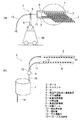
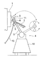
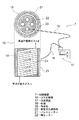
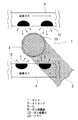
以下、図面を参照しながら説明する。図1は本発明のストランド成形方法及び成形装置の一実施の形態を示す高温不活性ガス噴霧装置の模式的な構成図である。また、図2は高温不活性ガス噴霧装置の使用例を説明する模式的な図、図3はガス噴霧器の模式的な斜視図、図4は加熱装置の模式的な構成図、図5はダイス穴の近傍の模式的な状態説明図、図6は品質低下とならないペレットの模式的な斜視図である。 Hereinafter, description will be given with reference to the drawings. FIG. 1 is a schematic configuration diagram of a high-temperature inert gas spraying apparatus showing an embodiment of a strand forming method and a forming apparatus of the present invention. 2 is a schematic diagram for explaining an example of use of a high-temperature inert gas spraying device, FIG. 3 is a schematic perspective view of a gas sprayer, FIG. 4 is a schematic configuration diagram of a heating device, and FIG. 5 is a die. FIG. 6 is a schematic perspective view of a pellet that does not deteriorate in quality.
図1において、ストランド成形装置は、コンパウンドを混練した後にダイス1を介してストランド2を押し出す公知の混練機と、ダイス1の複数の穴3に窒素ガス(ここでは窒素ガスを使用しているが、他の不活性ガスであっても良いものとする)を噴霧し、複数の穴3の周辺を窒素ガスで充満させる高温不活性ガス噴霧装置4とを備えて構成されている。ストランド成形装置の下流側には、特に図示しないが、各穴3から押し出されてきた各ストランド2を所定の長さにカットしてペレット化する公知の回転刃カッター装置が備えられている。
In FIG. 1, the strand forming apparatus uses a known kneader that extrudes the
ダイス1には、複数の穴3が形成されている。複数の穴3は、所定の間隔で横一列に並ぶように形成されている。本形態では、円形の穴3が10個形成されている(一例であるものとする)。
A plurality of
高温不活性ガス噴霧装置4は、高温の窒素ガスを均一な風量でダイス1の各穴3に向けて噴霧することができるように構成されている。具体的な一例として、高温不活性ガス噴霧装置4は、一対のガス噴霧器5と、風量調節装置6と、加熱装置7とを備えて構成されている。また、高温不活性ガス噴霧装置4は、図2に示す如く、角度調節機構8を有する可動アーム9と、移動用台車10とを備えて構成されている。
The high temperature inert
図1及び図3において、一対のガス噴霧器5は、それぞれダイス1の穴3が並ぶ方向に長くなる円筒形状に形成されている。一対のガス噴霧器5は、円筒の一端が塞がれており、他端は連結管11で繋がれている。一対のガス噴霧器5には、所定の間隔且つ大きさのガス噴霧穴12が複数形成されている。複数のガス噴霧穴12は、ダイス1の各穴3の位置に合わせて開口形成されている。連結管11には、ガス供給管13の一端が接続されている。本形態の一対のガス噴霧器5は、耐熱性を有するように形成されている。
1 and 3, the pair of
一対のガス噴霧器5は、可動アーム9の先端に設けられた角度調節機構8に取り付けられている。一対のガス噴霧器5は、ダイス1の複数の穴3に対して最適な角度に調節され、この上で使用されるようになっている。
The pair of
本形態の高温不活性ガス噴霧装置4は、ストランド2の成形時においてダイス1の近傍に配置されるのは勿論のこと、例えばダイス1の交換や装置メンテナンスに係る作業の際には、図2に示す如く、ダイス1から遠ざけることもできるように構成されている。本形態の高温不活性ガス噴霧装置4は、作業性にも配慮した構造を有している。本形態の高温不活性ガス噴霧装置4は、移動用台車10によって移動式の装置になっている。
The high-temperature inert
図1において、ガス供給管13の他端は、風量調節装置6に接続されている。風量調節装置6は、窒素ガスの風量を調節するための風量調節弁を含んで構成されている(風量調節弁を単独で使用しても良いものとする。また、弁を制御装置を用いて電気的に流量制御しても良いものとする)。
In FIG. 1, the other end of the
図1及び図4において、加熱装置7は、ガス供給管14を介して供給される例えば常温の窒素ガスを加熱するために備えられている。加熱装置7にて加熱された高温の窒素ガスは、ガス供給管15を介して風量調節装置6に供給されるようになっている。加熱装置7の具体的な一例を説明すると、加熱装置7は図4に示す如く、ガス加熱部16と、温調装置17と、配線18とを備えて構成されている。
1 and 4, the
ガス加熱部16は、略筒状の筒状部19と、この筒状部19に形成される螺旋ガス通路部20と、筒状部19の外周に設けられるバンドヒーター21と、螺旋ガス通路部20よりも筒状部19の内側に設けられる棒ヒーター22とを備えて構成されている。螺旋ガス通路部20は、窒素ガスを加熱するための通路であって、本形態においては特に限定するものでないが、加熱する距離をかせぐことができるように螺旋形状に形成されている。
The
ガス供給管14を介して供給される常温の窒素ガスは、螺旋ガス通路部20を通過することによりバンドヒーター21及び棒ヒーター22で所定の温度まで加熱された後、風量調節装置6に供給されるようになっている。尚、加熱する温度は、ダイス1の穴3に発生するメヤニ23(図5参照)が固化しないような温度であることが好ましいものとする。
The normal temperature nitrogen gas supplied through the
温調装置17は、バンドヒーター21及び棒ヒーター22の温度調節をするための装置として備えられている。本形態において、温調装置17、配線18、バンドヒーター21、棒ヒーター22は、市販のものが用いられている。
The
上記構成において、常温の窒素ガスを加熱装置7にて高温状態にするとともに、風量調節装置6を通過させると、風量と温度とが調節された高温の窒素ガスになる。そして、これを一対のガス噴霧器5に送った後に、図5に示す如く、ダイス1の各穴3に向けて(穴3の出口周辺に)噴霧する。この方法でダイス1の各穴3の周辺を高温の窒素ガスで充満させ、メヤニ23の酸化による変色を防止しつつ各穴3からストランド2を押し出し成形する。
In the above configuration, when normal temperature nitrogen gas is brought into a high temperature state by the
穴3の周辺に高温の窒素ガスが充満していることから、メヤニ23は酸化することなく、また、メヤニ23は固化することもない。
Since the periphery of the
本発明は、ダイスの穴の周りに付着するカスの成長とともに酸化が進行する従来のメヤニに対し、このメヤニの変色を防止し、これによってペレットの品質向上を図ることができるようにした発明となっている。また、上記説明からも分かるように、不活性ガスを充満させるケーシングや大きなスペースを必要としないことから、従来よりも装置構成の簡素化を図ることができる発明となっている。 The present invention is an invention in which discoloration of the main body is prevented with respect to the conventional main body in which oxidation proceeds with the growth of debris attached around the hole of the die, and thereby the quality of the pellet can be improved. It has become. Further, as can be seen from the above description, since a casing for filling with an inert gas and a large space are not required, the present invention is capable of simplifying the apparatus configuration as compared with the prior art.
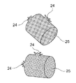
尚、本発明に関し、常温の窒素ガスを一対のガス噴霧器5まで供給するように構成しても良いものとする。この場合、加熱装置7を使用しないことになる。加熱装置7を使用しない場合、ダイス1の穴3が固化する可能性があるが、固化してもメヤニが酸化状態で固化したものではないことから、仮に混入しても品質不良を誘発するようなことはない。図6はメヤニ24が付着した状態で製造されたペレット25を示しているが、酸化によってメヤニ24は変色しているものでないことから、当然にコンパウンドと同色であり、上記の如く品質上の問題もない。
In addition, regarding this invention, you may comprise so that normal temperature nitrogen gas may be supplied to a pair of
この他、本発明は本発明の主旨を変えない範囲で種々変更実施可能なことは勿論である。 In addition, the present invention can of course be modified in various ways within the scope not changing the gist of the present invention.
1 ダイス
2 ストランド
3 穴
4 高温不活性ガス噴霧装置
5 ガス噴霧器
6 風量調節装置
7 加熱装置
8 角度調節機構
9 可動アーム
10 移動用台車
11 連結管
12 ガス噴霧穴
13〜15 ガス供給管
16 ガス加熱部
17 温調装置
18 配線
19 筒状部
20 螺旋ガス通路部
21 バンドヒーター
22 棒ヒーター
23、24 メヤニ
25 ペレット
DESCRIPTION OF
Claims (5)
ことを特徴とするストランド成形方法。 A strand forming method comprising: extruding a strand from the hole while spraying an inert gas toward the die or the hole of the die.
前記不活性ガスを加熱装置で加熱するとともに風量調節装置で風量を調節しつつ噴霧する
ことを特徴とするストランド成形方法。 The strand forming method according to claim 1,
A strand forming method, wherein the inert gas is heated by a heating device and sprayed while adjusting an air volume with an air volume adjusting device.
ことを特徴とするストランド成形装置。 A strand forming apparatus comprising: a gas sprayer that sprays an inert gas toward a die or a hole of the die in the vicinity of the hole.
前記ガス噴霧器の上流に、前記不活性ガスを加熱する加熱装置と、前記不活性ガスの風量を調節する風量調節装置とを備える
ことを特徴とするストランド成形装置。 In the strand forming apparatus according to claim 3,
A strand forming apparatus comprising a heating device for heating the inert gas and an air volume adjusting device for adjusting an air volume of the inert gas upstream of the gas sprayer.
前記ガス噴霧器を前記穴に対して近接離間させる可動アームと、該可動アームに取り付けた前記ガス噴霧器の取り付け角度を可変させる角度調節機構とを備える
ことを特徴とするストランド成形装置。 In the strand forming apparatus according to claim 3 or 4,
A strand forming apparatus, comprising: a movable arm that moves the gas sprayer close to and away from the hole; and an angle adjustment mechanism that varies an attachment angle of the gas sprayer attached to the movable arm.
Priority Applications (6)
| Application Number | Priority Date | Filing Date | Title |
|---|---|---|---|
| JP2008005245A JP2009166301A (en) | 2008-01-15 | 2008-01-15 | Strand forming method and forming apparatus |
| MX2010007789A MX2010007789A (en) | 2008-01-15 | 2009-01-15 | Method and apparatus for forming strands. |
| TW098101359A TWI383877B (en) | 2008-01-15 | 2009-01-15 | Method and apparatus for forming strands |
| CN200980101952XA CN101909838A (en) | 2008-01-15 | 2009-01-15 | Method and apparatus for forming strands |
| PT2009050904A PT2009091073W (en) | 2008-01-15 | 2009-01-15 | Method and apparatus for forming strands |
| PCT/JP2009/050904 WO2009091073A1 (en) | 2008-01-15 | 2009-01-15 | Method and apparatus for forming strands |
Applications Claiming Priority (1)
| Application Number | Priority Date | Filing Date | Title |
|---|---|---|---|
| JP2008005245A JP2009166301A (en) | 2008-01-15 | 2008-01-15 | Strand forming method and forming apparatus |
Publications (1)
| Publication Number | Publication Date |
|---|---|
| JP2009166301A true JP2009166301A (en) | 2009-07-30 |
Family
ID=40885451
Family Applications (1)
| Application Number | Title | Priority Date | Filing Date |
|---|---|---|---|
| JP2008005245A Abandoned JP2009166301A (en) | 2008-01-15 | 2008-01-15 | Strand forming method and forming apparatus |
Country Status (6)
| Country | Link |
|---|---|
| JP (1) | JP2009166301A (en) |
| CN (1) | CN101909838A (en) |
| MX (1) | MX2010007789A (en) |
| PT (1) | PT2009091073W (en) |
| TW (1) | TWI383877B (en) |
| WO (1) | WO2009091073A1 (en) |
Families Citing this family (5)
| Publication number | Priority date | Publication date | Assignee | Title |
|---|---|---|---|---|
| DE102009059306A1 (en) * | 2009-12-23 | 2011-06-30 | Automatik Plastics Machinery GmbH, 63762 | Apparatus for continuous casting of strands of thermoplastic material |
| DE102011106709A1 (en) * | 2011-07-06 | 2013-01-10 | Automatik Plastics Machinery Gmbh | Method and device for producing granules |
| CN103707483B (en) * | 2013-12-25 | 2016-04-27 | 上海金发科技发展有限公司 | A kind of device prevented at mouth mould position generation carbide in granulation process |
| DE102016117213B4 (en) * | 2016-09-13 | 2019-02-07 | Maag Automatik Gmbh | Method and apparatus for extruding plastics |
| EP4674592A1 (en) | 2024-07-04 | 2026-01-07 | Feddem GmbH & Co. KG | Method and apparatus for forming polymer strands using a mold |
Family Cites Families (8)
| Publication number | Priority date | Publication date | Assignee | Title |
|---|---|---|---|---|
| US4461737A (en) * | 1983-02-09 | 1984-07-24 | Phillips Petroleum Company | Method and apparatus for forming pellets |
| JPH01213409A (en) * | 1988-02-17 | 1989-08-28 | Showa Denko Kk | Production of organic short fiber containing microfiber |
| JP2000280240A (en) * | 1999-03-31 | 2000-10-10 | Nippon Zeon Co Ltd | Pellet and method for producing the same |
| FR2813817B1 (en) * | 2000-09-13 | 2002-10-18 | Air Liquide | DEVICE FOR SHAPING PLASTIC OBJECTS UNDER AN INERT ATMOSPHERE |
| JP2003220607A (en) * | 2002-01-30 | 2003-08-05 | Asahi Kasei Corp | Protective device |
| US7662332B2 (en) * | 2003-10-01 | 2010-02-16 | The Research Foundation Of State University Of New York | Electro-blowing technology for fabrication of fibrous articles and its applications of hyaluronan |
| JP2005224982A (en) * | 2004-02-10 | 2005-08-25 | Nippon Ester Co Ltd | Polymer granulator |
| JP2008068517A (en) * | 2006-09-14 | 2008-03-27 | Mitsubishi Chemicals Corp | Manufacturing method of resin pellets |
-
2008
- 2008-01-15 JP JP2008005245A patent/JP2009166301A/en not_active Abandoned
-
2009
- 2009-01-15 TW TW098101359A patent/TWI383877B/en not_active IP Right Cessation
- 2009-01-15 WO PCT/JP2009/050904 patent/WO2009091073A1/en not_active Ceased
- 2009-01-15 CN CN200980101952XA patent/CN101909838A/en active Pending
- 2009-01-15 PT PT2009050904A patent/PT2009091073W/en unknown
- 2009-01-15 MX MX2010007789A patent/MX2010007789A/en not_active Application Discontinuation
Also Published As
| Publication number | Publication date |
|---|---|
| CN101909838A (en) | 2010-12-08 |
| PT2009091073W (en) | 2012-11-02 |
| TW200936344A (en) | 2009-09-01 |
| TWI383877B (en) | 2013-02-01 |
| MX2010007789A (en) | 2010-08-04 |
| WO2009091073A1 (en) | 2009-07-23 |
Similar Documents
| Publication | Publication Date | Title |
|---|---|---|
| JP2009166301A (en) | Strand forming method and forming apparatus | |
| KR101591121B1 (en) | Method and device for extrusion of hollow pellets | |
| CN104816445B (en) | Production line for machining PE (polyethylene) pipes | |
| DE202012012967U1 (en) | Welding torch with gas flow control | |
| US20170182701A1 (en) | Extruder for three-dimensional additive printer | |
| WO2018115467A1 (en) | A print head adjusting structure for a 3d printer | |
| RU2012141045A (en) | DEVICE AND METHOD FOR PRODUCTION OF PRODUCTS | |
| CN101774084A (en) | Method and device for light, powder and gas coaxial transmission laser cladding forming manufacturing | |
| US10150249B2 (en) | Dual head extruder for three-dimensional additive printer | |
| JP2016172251A (en) | Flat jet nozzle and usage of flat jet nozzle | |
| EP1488910B1 (en) | Apparatus for manufacturing a thermoplastic film | |
| CN104884189A (en) | Hybrid cooling nozzle apparatus, and method for controlling cooling nozzle of continuous casting equipment using same | |
| CA2679422C (en) | Method and device for the continuous production of a plastic compound pipe comprising a pipe socket | |
| KR101878076B1 (en) | Arc welding device | |
| JP2019081187A (en) | Method for manufacturing laminated shaped object | |
| CA2376398A1 (en) | Rotating extrusion die with spray nozzle | |
| JP2014172250A (en) | Rubber member molding device | |
| JP3908504B2 (en) | Resin extruder die apparatus and extrusion molding method | |
| US20180043600A1 (en) | Extruder die plate for reduced strand surging | |
| JP2019089250A (en) | Breaker plate, strand manufacturing apparatus, pellet manufacturing apparatus and pellet manufacturing method | |
| CN107855530B (en) | Three-dimensional printing extrusion device, three-dimensional printer and manufacturing method thereof | |
| JP5841610B2 (en) | Extrusion equipment especially for plastic materials | |
| AT505894B1 (en) | GRANULATING DEVICE AND GRANULAR PLATE | |
| CN214767881U (en) | Spraying on-line quenching device capable of automatically adjusting straightness during aluminum extrusion | |
| CN103464503B (en) | A kind of extruding die for aluminum shaped material |
Legal Events
| Date | Code | Title | Description |
|---|---|---|---|
| A621 | Written request for application examination |
Free format text: JAPANESE INTERMEDIATE CODE: A621 Effective date: 20101130 |
|
| A762 | Written abandonment of application |
Free format text: JAPANESE INTERMEDIATE CODE: A762 Effective date: 20120214 |