JP2009156384A - Vibration control device - Google Patents
Vibration control device Download PDFInfo
- Publication number
- JP2009156384A JP2009156384A JP2007336876A JP2007336876A JP2009156384A JP 2009156384 A JP2009156384 A JP 2009156384A JP 2007336876 A JP2007336876 A JP 2007336876A JP 2007336876 A JP2007336876 A JP 2007336876A JP 2009156384 A JP2009156384 A JP 2009156384A
- Authority
- JP
- Japan
- Prior art keywords
- unit
- value
- load support
- vibration control
- acceleration
- Prior art date
- Legal status (The legal status is an assumption and is not a legal conclusion. Google has not performed a legal analysis and makes no representation as to the accuracy of the status listed.)
- Granted
Links
Images


Landscapes
- Seats For Vehicles (AREA)
- Vibration Prevention Devices (AREA)
Abstract
Description
本発明は、荷重支持部等、特に移動体等に設置される荷重支持部等に加わる振動を抑制又は低減する振動制御装置に関する。 The present invention relates to a vibration control device that suppresses or reduces vibration applied to a load support portion and the like, particularly a load support portion and the like installed on a moving body or the like.
従来、振動加速度に応じて 座席下の直動型電動アクチュエータを動作制御して座席に加わる振動を抑制する座席用振動制御装置がある(特許文献1参照)。 2. Description of the Related Art Conventionally, there is a seat vibration control device that suppresses vibration applied to a seat by controlling the operation of a direct-acting electric actuator under the seat according to vibration acceleration (see Patent Document 1).
しかしながら、図10(a)に示すように、座席Sの支持をアクチュエータ121のみでする場合、停止状態を含め常にアクチュエータ121の出力が必要となる。また、図10(b)に示すように、座席Sの支持をアクチュエータ121とトーションスプリング122でする場合、停止状態ではアクチュエータ121の出力を0とすることができるが、座席Sの振動を制御する場合、トーションスプリング122のバネ力が反力となってしまい、振動制御分の出力の他にバネの反力分の出力がアクチュエータ121に必要となり、大きな出力が要求されていた。
However, as shown in FIG. 10 (a), when the seat S is supported only by the
図11に示すように、アクチュエータは、静止状態から指令値を受けた場合に、摩擦力等の影響によりすぐに動作することができない。そのため、静止領域から動作領域へ移行する際に、衝撃を感じることがあった。 As shown in FIG. 11, when receiving a command value from a stationary state, the actuator cannot immediately operate due to the influence of frictional force or the like. Therefore, an impact may be felt when moving from the stationary region to the operating region.
さらに、この摩擦力等は、製品によるばらつき、温度等の使用環境による変化及び経時劣化等により、変化するため、常に装置の状況に応じた制御をする必要がある、 Furthermore, since this frictional force changes due to variations in products, changes due to usage environments such as temperature and deterioration over time, it is necessary to always control according to the status of the device.
本発明は、上記課題を解決するものであって、静止領域から動作領域まで円滑に作動することができると共に、常に装置の状況に応じた制御をすることができる振動制御装置を提供することを目的とする。 The present invention solves the above-described problem, and provides a vibration control device that can operate smoothly from a stationary region to an operation region and can always perform control according to the state of the device. Objective.
そのために本発明は、設置部に設置された荷重支持部と、所定の制御周期を有し、前記荷重支持部の前記設置部に対する振動を制御する振動制御手段を有する振動制御部と、前記設置部の加速度を検出する設置部加速度検出手段と、前記荷重支持部の加速度を検出する荷重支持部加速度検出手段と、を備え、前記振動制御部は、前記設置部加速度検出手段の検出値と、前記荷重支持部加速度検出手段の検出値とから、前記設置部に対して前記荷重支持部が静止領域か、動作領域かを判断し、前記荷重支持部が静止領域の場合、前記設置部加速度検出手段の検出値と、前記荷重支持部加速度検出手段の検出値とから算出した前記振動制御手段の制振出力値に静止領域補償値を付加して静止領域出力値を算出し、今回の制御周期において前記荷重支持部が動作領域の場合、且つ、前回の制御周期において前記荷重支持部が静止領域の場合、前記静止領域補償値を付加した前記振動制御手段の制振出力値に、動作領域補償値を付加して動作領域出力値を算出し、今回の制御周期において前記荷重支持部が動作領域の場合、且つ、前回の制御周期において前記荷重支持部が動作領域の場合、前記荷重支持部の加速度の絶対値が所定の閾値より大きいか判断し、前記荷重支持部の加速度の絶対値が所定の閾値より大きい場合、前記静止領域補償値を変更し、変更後の前記静止領域補償値を付加した前記振動制御手段の制振出力値に、動作領域補償値を付加して動作領域出力値を算出することを特徴とする。 For this purpose, the present invention provides a load support unit installed in an installation unit, a vibration control unit having a predetermined control cycle, and having a vibration control means for controlling vibration of the load support unit with respect to the installation unit, and the installation An installation part acceleration detection means for detecting the acceleration of the part, and a load support part acceleration detection means for detecting the acceleration of the load support part, wherein the vibration control unit has a detection value of the installation part acceleration detection means, From the detection value of the load support unit acceleration detection means, it is determined whether the load support unit is a stationary region or an operation region with respect to the installation unit. If the load support unit is a stationary region, the installation unit acceleration detection is performed. A stationary region output value is calculated by adding a stationary region compensation value to the vibration damping output value of the vibration control unit calculated from the detected value of the unit and the detected value of the load support unit acceleration detecting unit, and this control cycle In said load When the holding part is in the operating area and the load supporting part is in the stationary area in the previous control cycle, the operating area compensation value is added to the vibration damping output value of the vibration control means added with the stationary area compensation value. When the load support portion is in the motion region in the current control cycle, and the load support portion is in the motion region in the previous control cycle, the absolute value of the acceleration of the load support portion is calculated. Judgment whether the value is larger than a predetermined threshold value, and if the absolute value of acceleration of the load support portion is larger than a predetermined threshold value, change the static area compensation value and add the changed static area compensation value to the vibration The motion region output value is calculated by adding the motion region compensation value to the vibration suppression output value of the control means.
また、前記振動制御部は、前記荷重支持部の加速度の絶対値が所定の閾値より大きい場合であって、且つ、前記設置部加速度検出手段の検出値と前記荷重支持部加速度検出手段の検出値の符号が一致している場合、前記静止領域補償値を所定量減少させ、前記荷重支持部の加速度の絶対値が所定の閾値より大きい場合であって、且つ、前記設置部加速度検出手段の検出値と前記荷重支持部加速度検出手段の検出値の符号が一致していない場合、前記静止領域補償値を所定量増加させることを特徴とする。 Further, the vibration control unit is a case where the absolute value of the acceleration of the load support unit is larger than a predetermined threshold, and the detection value of the installation unit acceleration detection unit and the detection value of the load support unit acceleration detection unit Are equal to each other, the stationary region compensation value is decreased by a predetermined amount, and the absolute value of the acceleration of the load supporting portion is larger than a predetermined threshold, and the detection by the installation portion acceleration detecting means is performed. When the value and the sign of the detection value of the load support portion acceleration detection means do not match, the still region compensation value is increased by a predetermined amount.
また、前記荷重支持部と連結され、荷重と釣り合う負荷を与えるカウンタバランス部と、を有することを特徴とする。 And a counter balance portion that is connected to the load support portion and applies a load that balances the load.
また、前記荷重支持部は、前記設置部に対して相対移動する第1移動手段を有することを特徴とする。 In addition, the load support portion includes first moving means that moves relative to the installation portion.
また、前記カウンタバランス部は、前記荷重支持部に対して相対移動する第2移動手段を有することを特徴とする。 In addition, the counter balance unit includes a second moving unit that moves relative to the load support unit.
また、前記設置部に一端を支持された付勢手段と、前記設置部に支点を枢支され、一端を前記スライド手段に回動可能に接合され、他端を付勢手段の他端に回動可能に接合した天秤部と、前記天秤部の長さを変更する調整手段とを備えたことを特徴とする。 Further, an urging means supported at one end by the installation part, a fulcrum is pivotally supported by the installation part, one end is pivotally joined to the slide means, and the other end is rotated to the other end of the urging means. It is characterized by comprising a balance part movably joined and an adjusting means for changing the length of the balance part.
また、前記荷重支持部材上の荷重を検知する検知手段を備え、前記検知手段で検知した荷重に応じて前記調整手段を作動することを特徴とする。 In addition, a detection unit that detects a load on the load support member is provided, and the adjustment unit is operated according to the load detected by the detection unit.
請求項1記載の発明によれば、設置部に設置された荷重支持部と、所定の制御周期を有し、前記荷重支持部の前記設置部に対する振動を制御する振動制御手段を有する振動制御部と、前記設置部の加速度を検出する設置部加速度検出手段と、前記荷重支持部の加速度を検出する荷重支持部加速度検出手段と、を備え、前記振動制御部は、前記設置部加速度検出手段の検出値と、前記荷重支持部加速度検出手段の検出値とから、前記設置部に対して前記荷重支持部が静止領域か、動作領域かを判断し、前記荷重支持部が静止領域の場合、前記設置部加速度検出手段の検出値と、前記荷重支持部加速度検出手段の検出値とから算出した前記振動制御手段の制振出力値に静止領域補償値を付加して静止領域出力値を算出し、今回の制御周期において前記荷重支持部が動作領域の場合、且つ、前回の制御周期において前記荷重支持部が静止領域の場合、前記静止領域補償値を付加した前記振動制御手段の制振出力値に、動作領域補償値を付加して動作領域出力値を算出し、今回の制御周期において前記荷重支持部が動作領域の場合、且つ、前回の制御周期において前記荷重支持部が動作領域の場合、前記荷重支持部の加速度の絶対値が所定の閾値より大きいか判断し、前記荷重支持部の加速度の絶対値が所定の閾値より大きい場合、前記静止領域補償値を変更し、変更後の前記静止領域補償値を付加した前記振動制御手段の制振出力値に、動作領域補償値を付加して動作領域出力値を算出するので、静止領域から動作領域まで円滑に作動することができると共に、常に装置の状況に応じた制御をすることができる。また、補償値に過不足が存在する場合にすぐに調整することができる。 According to invention of Claim 1, the vibration control part which has a vibration control means which has a predetermined control cycle and controls the vibration with respect to the said installation part of the load support part installed in the installation part. And an installation part acceleration detection means for detecting the acceleration of the installation part, and a load support part acceleration detection means for detecting the acceleration of the load support part, wherein the vibration control unit is a part of the installation part acceleration detection means. From the detection value and the detection value of the load support unit acceleration detection means, it is determined whether the load support unit is a stationary region or an operation region with respect to the installation unit, and when the load support unit is a stationary region, A static region output value is calculated by adding a static region compensation value to the vibration damping output value of the vibration control unit calculated from the detection value of the installation unit acceleration detection unit and the detection value of the load support unit acceleration detection unit, In this control cycle When the load support portion is in the motion region and the load support portion is in the static region in the previous control cycle, the motion region compensation value is added to the vibration suppression output value of the vibration control means to which the static region compensation value is added. To calculate the motion region output value, and if the load support portion is in the motion region in the current control cycle and if the load support portion is in the motion region in the previous control cycle, the acceleration of the load support portion If the absolute value of the load support portion acceleration is greater than a predetermined threshold, the static region compensation value is changed, and the changed static region compensation value is added. Since the motion region output value is calculated by adding the motion region compensation value to the vibration damping output value of the vibration control means, it can operate smoothly from the stationary region to the motion region, and always according to the situation of the device. System It can be a to. Further, when the compensation value is excessive or insufficient, it can be adjusted immediately.
請求項2記載の発明によれば、前記振動制御部は、前記荷重支持部の加速度の絶対値が所定の閾値より大きい場合であって、且つ、前記設置部加速度検出手段の検出値と前記荷重支持部加速度検出手段の検出値の符号が一致している場合、前記静止領域補償値を所定量減少させ、前記荷重支持部の加速度の絶対値が所定の閾値より大きい場合であって、且つ、前記設置部加速度検出手段の検出値と前記荷重支持部加速度検出手段の検出値の符号が一致していない場合、前記静止領域補償値を所定量増加させるので、補償値に過不足が存在する場合に効率的に調整することができる。 According to a second aspect of the present invention, the vibration control unit is a case where the absolute value of the acceleration of the load support unit is larger than a predetermined threshold, and the detected value of the installation unit acceleration detection means and the load When the signs of the detection values of the support portion acceleration detection means match, the static region compensation value is decreased by a predetermined amount, the absolute value of the acceleration of the load support portion is greater than a predetermined threshold, and When the detection value of the installation portion acceleration detection means and the detection value of the load support portion acceleration detection means do not coincide with each other, the static region compensation value is increased by a predetermined amount. Can be adjusted efficiently.
請求項3記載の発明によれば、前記荷重支持部と連結され、荷重と釣り合う負荷を与えるカウンタバランス部と、を有するので、振動制御手段の出力を低減することができ、小型の振動制御手段で実現できる効率的な振動制御装置を提供することができる。 According to a third aspect of the present invention, since the counter balance unit is connected to the load support unit and applies a load that balances the load, the output of the vibration control unit can be reduced, and the compact vibration control unit can be reduced. It is possible to provide an efficient vibration control device that can be realized with the above.
請求項4記載の発明によれば、前記荷重支持部は、前記設置部に対して相対移動する第1移動手段を有するので、荷重支持部材が水平方向に移動しないようにすることができる。 According to invention of Claim 4, since the said load support part has a 1st moving means which moves relatively with respect to the said installation part, it can prevent a load support member from moving to a horizontal direction.
請求項5記載の発明によれば、前記カウンタバランス部は、前記荷重支持部に対して相対移動する第2移動手段を有するので、カウンタバランス部を移動させる必要がなくなる。 According to the fifth aspect of the present invention, since the counter balance portion has the second moving means that moves relative to the load support portion, it is not necessary to move the counter balance portion.
請求項6記載の発明によれば、前記設置部に一端を支持された付勢手段と、前記設置部に支点を枢支され、一端を前記スライド手段に回動可能に接合され、他端を付勢手段の他端に回動可能に接合した天秤部と、前記天秤部の長さを変更する調整手段とを備えたので、カウンタウエイト等の重量物を適用する必要がなくなる。 According to the sixth aspect of the present invention, the urging means whose one end is supported by the installation portion, the fulcrum is pivotally supported by the installation portion, the one end is rotatably joined to the slide means, and the other end is Since the balance part pivotally joined to the other end of the urging means and the adjusting means for changing the length of the balance part are provided, it is not necessary to apply a heavy object such as a counterweight.
請求項7記載の発明によれば、前記荷重支持部材上の荷重を検知する検知手段を備え、前記検知手段で検知した荷重に応じて前記調整手段を作動するので、初期荷重の変化に対して適切に対応することができる。 According to the seventh aspect of the present invention, since the detecting means for detecting the load on the load supporting member is provided and the adjusting means is operated according to the load detected by the detecting means, Can respond appropriately.
以下、本発明の好ましい実施の形態について図面を参照して説明する。 Hereinafter, preferred embodiments of the present invention will be described with reference to the drawings.
図1は、本実施形態における振動制御装置1を示す。図中、1は振動制御装置、10は荷重支持部、11は第1案内手段の一例としての第1スライダレール、12は第1移動手段の一例としての第1スライダ、13は荷重支持部材、20は所定の制御周期で駆動される振動制御部、21は振動制御手段の一例としての制振用アクチュエータ、22は検知手段の一例としての荷重センサ、23は検知手段の一例としての加速度センサ、30はカウンタバランス部、31は第2案内手段の一例としての第2スライダレール、32は第2移動手段の一例としての第2スライダ、33は第2移動手段支持部の一例としての第2スライダ支持部、34は調整手段の一例としてのプリロード調整用アクチュエータ、35はねじりバネ、Fは設置部、Sは座席である。
FIG. 1 shows a vibration control device 1 according to this embodiment. In the figure, 1 is a vibration control device, 10 is a load support section, 11 is a first slider rail as an example of first guide means, 12 is a first slider as an example of first movement means, 13 is a load support member, 20 is a vibration control unit driven at a predetermined control cycle, 21 is a vibration control actuator as an example of vibration control means, 22 is a load sensor as an example of detection means, 23 is an acceleration sensor as an example of detection means, 30 is a counter balance section, 31 is a second slider rail as an example of second guiding means, 32 is a second slider as an example of second moving means, and 33 is a second slider as an example of second moving means support section. A
振動制御装置1は、荷重支持部10により床や車両のシャシ等の設置部Fに設置され、振動制御部20で振動制御装置1上の車両キャビン等の座席S等の荷重の振動をアクティブに制御すると共に、カウンタバランス部30で荷重に対する力の釣り合いを設定するものである。
The vibration control device 1 is installed on the installation portion F such as a floor or a vehicle chassis by the
荷重支持部10は、設置部Fに設置された第1スライダレール11、荷重支持部材13に設けた第1スライダ12及び座席Sを支持する荷重支持部材13等を有する。第1スライダレール11は、設置部Fに設置され、第1スライダ12及び荷重支持部材13を上下方向に案内する。第1スライダ12は、荷重支持部材13に設けられ、第1スライダレール11により上下方向に案内される。荷重支持部材13は、座席Sの下方に設置され、第1スライダレール11により上下方向に案内される第1スライダ12を有し、振動制御部20及びカウンタバランス部30に載置されている。
The
振動制御部20は、ボイスコイルモータ等の制振用アクチュエータ21、設置部加速度センサ22、座席加速度センサ23、荷重センサ24等を有する。制振用アクチュエータ21は、下部を設置部Fに設置、上部を荷重支持部材13に当接され、設置部加速度センサ22及び座席加速度センサ23等からの信号により、上下伸縮可能に制御される。
The
カウンタバランス部30は、第2スライダレール31、第2スライダ32、天秤部33、プリロード調整用アクチュエータ34、スプリング35等を有する。第2スライダレール31は、荷重支持部材13に設置され、第2スライダ32を移動可能に案内する。第2スライダ32は、天秤部33の一端に連結されると共に、第2スライダレール31に案内され、荷重支持部材13に対して移動可能なものである。
The
天秤部33は、設置部Fに支点33aを有し、一端側33bを第2スライダ32に、他端側33cをプリロード調整用アクチュエータ34を介してスプリング35に回動可能に連結する。
The
プリロード調整用アクチュエータ34は、長さを可変することができるもので、一端を天秤部33に連結され、他端をスプリング35に固着され、荷重センサ24等の信号により、伸縮可能に制御される。スプリング35は、一端をプリロード調整用アクチュエータ34に固着され、他端を設置部Fに固着されている。
The
図2は、このような構造の振動制御装置1のブロック図を示す。設置部加速度センサ22、座席加速度センサ23等からの入力信号を制御手段としてのECU40に入力し、制振用アクチュエータ21を制御することで、アクティブに振動を制御する。荷重センサ24等の入力信号を制御手段としてのECU40に入力し、プリロード調整用アクチュエータ34を制御する。
FIG. 2 shows a block diagram of the vibration control apparatus 1 having such a structure. Input signals from the installation
次に、プリロード調整制御について説明する。図3は、プリロード調整制御のフローチャートを示す。まず、ステップ1で、振動のない停止時における荷重を荷重センサ22により検出する(ST1)。次に、ステップ2で、検出した荷重値の一定時間分をECU40に読み込む(ST2)。続いて、ステップ3で、一定時間分の荷重値から例えば平均値を計算して基準荷重値を算出する(ST3)。次に、ステップ4で、算出した基準荷重値にあわせてプリロード調整用アクチュエータ34を作動制御する(ST4)。
Next, preload adjustment control will be described. FIG. 3 shows a flowchart of the preload adjustment control. First, in step 1, the load at the time of stopping without vibration is detected by the load sensor 22 (ST1). Next, in step 2, the detected load value for a certain time is read into the ECU 40 (ST2). Subsequently, in step 3, for example, an average value is calculated from the load values for a certain period of time to calculate a reference load value (ST3). Next, in step 4, the
図4は、プリロード調整制御前後の本実施形態の振動制御装置1の状態を示すもので、図4(a)はプリロード調整制御前、図4(b)はプリロード調整制御後の状態を示すものである。図4(a)に示すプリロード調整制御前の状態から、例えば乗員Pが座席Sに座り、初期荷重に乗員Pの荷重が足されると、カウンタバランス部30の天秤部33が反時計方向に回転し、スプリング35に負荷がかかる。そこで、図4(b)に示すように、プリロード調整用アクチュエータ34を作動させ、天秤部33の長さを変えることにより、荷重とスプリング35による負荷とを釣り合わせる。
FIG. 4 shows the state of the vibration control device 1 of this embodiment before and after the preload adjustment control. FIG. 4A shows the state before the preload adjustment control, and FIG. 4B shows the state after the preload adjustment control. It is. From the state before the preload adjustment control shown in FIG. 4A, for example, when the occupant P sits on the seat S and the load of the occupant P is added to the initial load, the
このように、プリロード調整用アクチュエータ34を作動させることにより、荷重がキャンセルされ、その状態から振動制御をすることができるようになる。
Thus, by operating the
次に、本実施形態の振動制御について説明する。図5は、振動制御のフローチャートを示す。振動制御のフローチャートの制御内容は、振動制御部の所定の制御周期で繰り返され、前回とは制御周期の1周期前、すなわち前回の制御周期を示し、今回とは現在の制御周期を示す。なお、前回と今回の表現は適宜記載する。まず、ステップ11で、振動時の加速度を加速度センサ23により検出する(ST11)。次に、ステップ12で、ECU40において制振用アクチュエータ21の推力を計算する(ST12)。推力計算は、例えば、加速度×フリクション×ゲイン×(−1)等の計算式やあらかじめ加速度に対応する推力の値を記憶しておくことにより実行する。ここで、計算式におけるゲインは制御の遅れ分、−1は向きの反転を表す。続いて、ステップ13で、ステップ12において計算した推力を制振用アクチュエータ21に指示する。
Next, the vibration control of this embodiment will be described. FIG. 5 shows a flowchart of vibration control. The control contents of the vibration control flowchart are repeated at a predetermined control cycle of the vibration control unit, the previous time being one cycle before the control cycle, that is, the previous control cycle, and the current time being the current control cycle. Note that the previous and current expressions will be described as appropriate. First, in
図6は、本実施形態の振動制御の状態を示すもので、図6(a)は制振用アクチュエータ21を収縮した状態、図6(b)は制振用アクチュエータ21を伸張した状態を示すものである。
6A and 6B show a state of vibration control according to the present embodiment. FIG. 6A shows a state where the damping
図6(a)はステップ14に対応する検出した荷重値がプリロード調整制御で求めた基準荷重値より大きい場合であり、座席S上の振動を0にするため制振用アクチュエータ21を収縮すると、スライダ32が前方に移動すると共に、カウンタバランス部30の天秤部33が反時計方向に回転する。この時、スプリング35は伸張するが、荷重とスプリング35による負荷は、ほぼ釣り合い状態を保つことができる。
FIG. 6A shows a case where the detected load value corresponding to step 14 is larger than the reference load value obtained by the preload adjustment control. When the damping
図6(b)はステップ15に対応する検出した荷重値がプリロード調整制御で求めた基準荷重値より小さい場合であり、座席S上の振動を0にするため制振用アクチュエータ21を伸張すると、第2スライダ32が後方に移動すると共に、カウンタバランス部30の天秤部33が時計方向に回転する。この時、スプリング35は収縮するが、荷重とスプリング35による負荷は、ほぼ釣り合い状態を保つことができる。
FIG. 6B shows a case where the detected load value corresponding to step 15 is smaller than the reference load value obtained by the preload adjustment control. When the
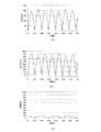
図7は、本実施形態の振動制御装置1を用いた場合と、図10に示す従来技術の場合とをシミュレーションで比較した結果を示す。シミュレーションは、振幅25mm周期750mmの波状路を速度70km/hで走行する条件で、荷重の振動を0にするために必要な制振用アクチュエータを求めた。 FIG. 7 shows the result of comparing the case of using the vibration control device 1 of the present embodiment and the case of the prior art shown in FIG. 10 by simulation. In the simulation, an actuator for vibration suppression necessary for reducing the vibration of the load to 0 under the condition of traveling on a wavy path with an amplitude of 25 mm and a period of 750 mm at a speed of 70 km / h was obtained.
図7(a)は、図10(a)に示すように、座席の支持をアクチュエータのみでする場合、図7(b)は、図10(b)に示すように、座席の支持をアクチュエータとスプリングでする場合、図7(c)は、本実施形態の場合である。 FIG. 7A shows the case where the seat is supported only by the actuator as shown in FIG. 10A, and FIG. 7B shows the case where the seat is supported by the actuator as shown in FIG. 10B. In the case of using a spring, FIG. 7C shows the case of this embodiment.
このように、本実施形態の振動制御装置1は、アクチュエータの出力を低減することができ、小型のアクチュエータで実現できる効率的なものである。 As described above, the vibration control device 1 of the present embodiment can reduce the output of the actuator, and is efficient that can be realized with a small actuator.
次に、本実施形態における補償制御について説明する。図11は、設置部Fが静止し、指令値が一定の場合の制振アクチュエータ21の推力に対する座席加速度を示すグラフである。図11に示すように、制振アクチュエータ21に作動指令信号が入力されているにも関わらず、座席Sは、クーロン摩擦力等により加速度の発生しない静止状態が存在する。補償制御は、この静止状態での制振アクチュエータ21の推力を補償する制御である。
Next, compensation control in this embodiment will be described. FIG. 11 is a graph showing the seat acceleration with respect to the thrust of the
なお、実際には、設置部Fも運動している場合もあるため、座席加速度ではなく、第1スライダ13が静止しているか運動しているかで状態を判断する。
Actually, since the installation part F may also be exercising, the state is determined based on whether the
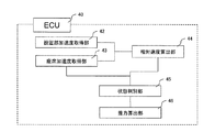
図8は、ECU40の補償制御に関係する部分を示した図である。 ECU40は、設置部加速度センサ22からの信号を取得する設置部加速度取得部42、座席加速度センサ23からの信号を取得する座席加速度取得部43、設置部加速度取得部42及び座席加速度取得部43からの信号から座席S又は第1スライダ13の設置部Fに対する相対速度を算出する相対速度算出部44、座席加速度取得部43で取得した座席Sの加速度と相対速度算出部44で算出した相対速度とから第1スライダ13が静止状態か運動状態か判別する状態判別部45、及び、状態判別部45で判別した結果に応じて制振アクチュエータ21の推力を算出する推力算出部46を有する。
FIG. 8 is a diagram showing a portion related to the compensation control of the
図9は、補償制御のフローチャートを示す図である。この補償制御のフローチャートは、図5に示した制振制御のフローチャートに補償制御を含む構成としてもよい。 FIG. 9 is a diagram illustrating a flowchart of compensation control. The flowchart of the compensation control may be configured to include compensation control in the flowchart of the vibration suppression control illustrated in FIG.
まず、ステップ21で、設置部加速度取得部42が設置部加速度センサ22から設置部加速度を取得する(ST21)。続いて、ステップ22で、座席加速度取得部43が座席加速度センサ23から座席加速度を取得する(ST22)。次に、ステップ23で、座席加速度に比例ゲインを乗算し、出力を求める(ST23)。続いて、ステップ24で、ステップ23において求めた値から相対速度算出部44が第1スライダ13の相対速度を算出する(ST24)。
First, in
次に、ステップ25で、ステップ24において求めた相対速度の絶対値と所定の閾値Aとの大きさを状態判別部45で比較する(ST25)。
Next, in step 25, the
ステップ25において、相対速度の絶対値が所定の閾値Aよりも小さい静止領域の場合、ステップ26で、座席加速度センサ23の検出値が閾値Bよりも大きいか判断する。
If it is determined in step 25 that the absolute value of the relative speed is a static region smaller than a predetermined threshold A, it is determined in step 26 whether the detected value of the
ステップ26において、座席加速度センサ23の検出値が閾値Bよりも大きい場合、ステップ27で、フラグをONする(ST27)。次に、ステップ28で、保存バッファに保存されたクーロン摩擦値をクーロン摩擦力の値とする(ST28)。
If the detected value of the
ステップ26において、座席加速度センサ23の検出値が閾値Bよりも小さい場合、ステップ28を実行する。
In step 26, when the detected value of the
次に、ステップ29で、推力算出部46で、ステップ23において求めた出力+クーロン摩擦力+粘性摩擦力を出力推力として算出する(ST29)。続いて、ステップ30で、制振アクチュエータ21に出力する(ST30)。
Next, in step 29, the
ステップ25において、相対速度の絶対値が所定の閾値Aよりも大きい動作領域の場合、ステップ31で、第1スライダ13は運動状態とみて、粘性摩擦力の値を計算する(ST31)。
If the absolute value of the relative speed is larger than the predetermined threshold A in step 25, the
次に、ステップ32で、フラグがONか判断する(ST32)。このステップ32におけるフラグは、今回の制御周期において前記荷重支持部が動作領域の場合、且つ、前回の制御周期において前記荷重支持部が静止領域の場合 または 今回の制御周期において前記荷重支持部が動作領域の場合、且つ、前回の制御周期において前記荷重支持部が動作領域の場合を判断するものである。
Next, in
ステップ32において、フラグがONと判断した場合、ステップ33で、フラグをOFFとする(ST33)。次に、ステップ34で、クーロン摩擦力の値を前回の出力値とし、このクーロン摩擦値を保存バッファに保存する(ST34)。その後、ステップ28〜ステップ30を実行する。
If it is determined in
また、ステップ32において、フラグがOFFと判断した場合、ステップ41で、座席加速度センサ23の検出値の絶対値が所定の閾値Cより大きいか判断する(ST41)。
If it is determined in
ステップ41において、座席加速度センサ23の検出値の絶対値が所定の閾値Cより小さいと判断した場合、ステップ28〜ステップ30を実行する。
If it is determined in step 41 that the absolute value of the detected value of the
ステップ41において、座席加速度センサ23の検出値の絶対値が所定の閾値Cより大きいと判断した場合、ステップ42で、座席加速度センサ23の検出値と設置部加速度センサ22の検出値の符号が一致するか判断する(ST42)。
If it is determined in step 41 that the absolute value of the detection value of the
ステップ42において、座席加速度センサ23の検出値と設置部加速度センサ22の検出値の符号が一致すると判断した場合、ステップ43で、前回出力したクーロン摩擦値を一定量下げて、保存バッファに保存する(ST43)。その後、ステップ28〜ステップ30を実行する。
If it is determined in
ステップ42において、座席加速度センサ23の検出値と設置部加速度センサ22の検出値の符号が一致しないと判断した場合、ステップ44で、前回出力したクーロン摩擦値を一定量上げて、保存バッファに保存する(ST44)。その後、ステップ28〜ステップ30を実行する。
If it is determined in
このように、本実施形態は、設置部Fに設置された荷重支持部10と、所定の制御周期を有し、荷重支持部10の設置部Fに対する振動を制御する制振アクチュエータ21を有する振動制御部20と、設置部Fの加速度を検出する設置部加速度センサ22と、荷重支持部10の加速度を検出する荷重支持部加速度センサ23と、を備え、振動制御部20は、設置部加速度センサ22の検出値と、座席加速度センサ23の検出値とから、設置部Fに対して荷重支持部10が静止領域か、動作領域かを判断し、荷重支持部10が静止領域の場合、設置部加速度センサ22の検出値と、座席加速度センサ23の検出値とから算出した制振アクチュエータ21の制振出力値に静止領域補償値を付加して静止領域出力値を算出し、今回の制御周期において荷重支持部10が動作領域の場合、且つ、前回の制御周期において荷重支持部10が静止領域の場合、静止領域補償値を付加した制振アクチュエータ21の制振出力値に、動作領域補償値を付加して動作領域出力値を算出し、今回の制御周期において荷重支持部10が動作領域の場合、且つ、前回の制御周期において荷重支持部10が動作領域の場合、荷重支持部10の加速度の絶対値が所定の閾値より大きいか判断し、荷重支持部10の加速度の絶対値が所定の閾値より大きい場合、静止領域補償値を変更し、変更後の静止領域補償値を付加した制振アクチュエータ21の制振出力値に、動作領域補償値を付加して動作領域出力値を算出するので、静止領域から動作領域まで円滑に作動することができると共に、常に装置の状況に応じた制御をすることができる。また、補償値に過不足が存在する場合にすぐに調整することができる。
Thus, the present embodiment is a vibration having the
また、振動制御部20は、荷重支持部10の加速度の絶対値が所定の閾値より大きい場合であって、且つ、設置部加速度センサ22の検出値と荷重支持部加速度センサ23の検出値の符号が一致している場合、静止領域補償値を所定量減少させ、荷重支持部10の加速度の絶対値が所定の閾値より大きい場合であって、且つ、設置部加速度センサ22の検出値と荷重支持部加速度センサ23の検出値の符号が一致していない場合、静止領域補償値を所定量増加させるので、補償値に過不足が存在する場合に効率的に調整することができる。
Further, the
また、荷重支持部10と連結され、荷重と釣り合う負荷を与えるカウンタバランス部30と、を有するので、制振アクチュエータ21の出力を低減することができ、小型の制振アクチュエータ21で実現できる効率的な振動制御装置1を提供することができる。
Moreover, since it has the
また、荷重支持部10は、設置部Fに対して相対移動する第1スライド12とを有するので、荷重支持部材13が水平方向に移動しないようにすることができる。
Moreover, since the
また、カウンタバランス部30は、荷重支持部10に対して相対移動する第2スライダ32を有するので、カウンタバランス部30を移動させる必要がなくなる。
Further, since the
また、設置部Fに一端を支持されたスプリング35と、設置部Fに支点を枢支され、一端を第2スライダ32に回動可能に接合され、他端をスプリング35の他端に回動可能に接合した天秤部33と、天秤部33の長さを変更するプリロード調整用アクチュエータ34とを備えたので、カウンタウエイト等の重量物を適用する必要がなくなる。
Further, a
また、荷重支持部材11上の荷重を検知する荷重センサ22又は加速度センサ23等を備え、荷重センサ22又は加速度センサ23等で検知した荷重に応じてプリロード調整用アクチュエータ34を作動するECU40を備えたので、初期荷重の変化に対して適切に対応することができる。
In addition, a
なお、本発明は、前記実施の形態に限定されるものではなく、本発明の趣旨に基づいて種々変形させることが可能であり、例えば、制御のフローチャートの処理順番なども適宜変更可能であり、それらを本発明の範囲から排除するものではない。 The present invention is not limited to the above-described embodiment, and various modifications can be made based on the spirit of the present invention. For example, the processing order of the control flowchart can be changed as appropriate. They are not excluded from the scope of the present invention.
1…振動制御装置、10…荷重支持部、11……第1スライダレール(第1案内手段)、12…第1スライダ(第1移動手段)、13…荷重支持部材、20…振動制御部、21…制振用アクチュエータ(振動制御手段)、22…設置部加速度センサ、23…座席加速度センサ、24…荷重センサ、30…カウンタバランス部、31…第2スライダレール(第2案内手段)、32…第2スライダ(第2移動手段)、33…天秤部、34…プリロード調整用アクチュエータ(調整手段)、35…スプリング(付勢手段)、40…ECU(制御手段) DESCRIPTION OF SYMBOLS 1 ... Vibration control apparatus, 10 ... Load support part, 11 ... 1st slider rail (1st guide means), 12 ... 1st slider (1st moving means), 13 ... Load support member, 20 ... Vibration control part, 21 ... Actuator for vibration control (vibration control means), 22 ... Installation part acceleration sensor, 23 ... Seat acceleration sensor, 24 ... Load sensor, 30 ... Counter balance part, 31 ... Second slider rail (second guide means), 32 ... second slider (second moving means), 33 ... balance section, 34 ... preload adjusting actuator (adjusting means), 35 ... spring (biasing means), 40 ... ECU (control means)
Claims (7)
所定の制御周期を有し、前記荷重支持部の前記設置部に対する振動を制御する振動制御手段を有する振動制御部と、
前記設置部の加速度を検出する設置部加速度検出手段と、
前記荷重支持部の加速度を検出する荷重支持部加速度検出手段と、
を備え、
前記振動制御部は、前記設置部加速度検出手段の検出値と、前記荷重支持部加速度検出手段の検出値とから、前記設置部に対して前記荷重支持部が静止領域か、動作領域かを判断し、 前記荷重支持部が静止領域の場合、前記設置部加速度検出手段の検出値と、前記荷重支持部加速度検出手段の検出値とから算出した前記振動制御手段の制振出力値に静止領域補償値を付加して静止領域出力値を算出し、
今回の制御周期において前記荷重支持部が動作領域の場合、且つ、前回の制御周期において前記荷重支持部が静止領域の場合、前記静止領域補償値を付加した前記振動制御手段の制振出力値に、動作領域補償値を付加して動作領域出力値を算出し、
今回の制御周期において前記荷重支持部が動作領域の場合、且つ、前回の制御周期において前記荷重支持部が動作領域の場合、前記荷重支持部の加速度の絶対値が所定の閾値より大きいか判断し、
前記荷重支持部の加速度の絶対値が所定の閾値より大きい場合、前記静止領域補償値を変更し、変更後の前記静止領域補償値を付加した前記振動制御手段の制振出力値に、動作領域補償値を付加して動作領域出力値を算出する
ことを特徴とする振動制御装置。 A load support section installed in the installation section;
A vibration control unit having a predetermined control cycle and having vibration control means for controlling vibration of the load support unit with respect to the installation unit;
Installation unit acceleration detection means for detecting the acceleration of the installation unit;
Load support portion acceleration detecting means for detecting acceleration of the load support portion;
With
The vibration control unit determines whether the load support unit is a stationary region or an operation region with respect to the installation unit from the detection value of the installation unit acceleration detection unit and the detection value of the load support unit acceleration detection unit. When the load support part is in a static region, the static region compensation is applied to the vibration suppression output value of the vibration control unit calculated from the detection value of the installation unit acceleration detection unit and the detection value of the load support unit acceleration detection unit. Add the value to calculate the static area output value,
When the load support portion is in the operation region in the current control cycle, and when the load support portion is in the static region in the previous control cycle, the vibration control means added with the static region compensation value is set to the vibration suppression output value. , Calculate the motion region output value by adding the motion region compensation value,
If the load support portion is in the operation region in the current control cycle and if the load support portion is in the operation region in the previous control cycle, it is determined whether the absolute value of the acceleration of the load support portion is greater than a predetermined threshold. ,
When the absolute value of the acceleration of the load support portion is larger than a predetermined threshold, the static region compensation value is changed, and the vibration control means to which the static region compensation value after the change is added is added to the vibration control output value of the vibration control means. A vibration control device that calculates an operation region output value by adding a compensation value.
前記荷重支持部の加速度の絶対値が所定の閾値より大きい場合であって、且つ、前記設置部加速度検出手段の検出値と前記荷重支持部加速度検出手段の検出値の符号が一致していない場合、前記静止領域補償値を所定量増加させる
ことを特徴とする請求項1に記載の振動制御装置。 The vibration control unit is a case where the absolute value of the acceleration of the load support unit is greater than a predetermined threshold, and the sign of the detection value of the installation unit acceleration detection unit and the detection value of the load support unit acceleration detection unit Are equal to each other, the static region compensation value is decreased by a predetermined amount,
The absolute value of the acceleration of the load support part is greater than a predetermined threshold value, and the detection value of the installation part acceleration detection means and the detection value of the load support part acceleration detection means do not match The vibration control device according to claim 1, wherein the static region compensation value is increased by a predetermined amount.
Priority Applications (1)
| Application Number | Priority Date | Filing Date | Title |
|---|---|---|---|
| JP2007336876A JP4936004B2 (en) | 2007-12-27 | 2007-12-27 | Vibration control device |
Applications Claiming Priority (1)
| Application Number | Priority Date | Filing Date | Title |
|---|---|---|---|
| JP2007336876A JP4936004B2 (en) | 2007-12-27 | 2007-12-27 | Vibration control device |
Publications (2)
| Publication Number | Publication Date |
|---|---|
| JP2009156384A true JP2009156384A (en) | 2009-07-16 |
| JP4936004B2 JP4936004B2 (en) | 2012-05-23 |
Family
ID=40960620
Family Applications (1)
| Application Number | Title | Priority Date | Filing Date |
|---|---|---|---|
| JP2007336876A Expired - Fee Related JP4936004B2 (en) | 2007-12-27 | 2007-12-27 | Vibration control device |
Country Status (1)
| Country | Link |
|---|---|
| JP (1) | JP4936004B2 (en) |
Citations (7)
| Publication number | Priority date | Publication date | Assignee | Title |
|---|---|---|---|---|
| JPH03238508A (en) * | 1990-02-16 | 1991-10-24 | Omron Corp | Nonlinear friction compensating device |
| JPH09319437A (en) * | 1996-05-24 | 1997-12-12 | Nippon Seiko Kk | Friction compensation type control method and device therefor |
| JPH10109581A (en) * | 1996-10-04 | 1998-04-28 | Mitsubishi Heavy Ind Ltd | Seat suspension system |
| JPH11180202A (en) * | 1997-12-24 | 1999-07-06 | Mitsubishi Heavy Ind Ltd | Vibration controller for seat |
| JP2000280807A (en) * | 1999-03-29 | 2000-10-10 | Unisia Jecs Corp | Seat suspension control device for vehicle |
| JP2006509673A (en) * | 2002-12-12 | 2006-03-23 | ダイムラークライスラー・アクチェンゲゼルシャフト | Vehicle seat provided with an active suspension having two degrees of freedom of movement |
| JP2006125633A (en) * | 2004-10-29 | 2006-05-18 | Bose Corp | Active suspending |
-
2007
- 2007-12-27 JP JP2007336876A patent/JP4936004B2/en not_active Expired - Fee Related
Patent Citations (7)
| Publication number | Priority date | Publication date | Assignee | Title |
|---|---|---|---|---|
| JPH03238508A (en) * | 1990-02-16 | 1991-10-24 | Omron Corp | Nonlinear friction compensating device |
| JPH09319437A (en) * | 1996-05-24 | 1997-12-12 | Nippon Seiko Kk | Friction compensation type control method and device therefor |
| JPH10109581A (en) * | 1996-10-04 | 1998-04-28 | Mitsubishi Heavy Ind Ltd | Seat suspension system |
| JPH11180202A (en) * | 1997-12-24 | 1999-07-06 | Mitsubishi Heavy Ind Ltd | Vibration controller for seat |
| JP2000280807A (en) * | 1999-03-29 | 2000-10-10 | Unisia Jecs Corp | Seat suspension control device for vehicle |
| JP2006509673A (en) * | 2002-12-12 | 2006-03-23 | ダイムラークライスラー・アクチェンゲゼルシャフト | Vehicle seat provided with an active suspension having two degrees of freedom of movement |
| JP2006125633A (en) * | 2004-10-29 | 2006-05-18 | Bose Corp | Active suspending |
Also Published As
| Publication number | Publication date |
|---|---|
| JP4936004B2 (en) | 2012-05-23 |
Similar Documents
| Publication | Publication Date | Title |
|---|---|---|
| US8746411B2 (en) | Elevator car positioning including gain adjustment based upon whether a vibration damper is activated | |
| GB2561990A (en) | Precision movement platform for single-drive rigid-flexible coupling, and method of realization and application thereof | |
| JP4266744B2 (en) | Elevator guide device | |
| US7909141B2 (en) | Elevator vibration damping system having damping control | |
| JP3639606B2 (en) | Method and apparatus for improving elevator ride comfort | |
| JP4873163B2 (en) | Vibration control device | |
| JP5166673B2 (en) | Vibration damping device for elevator car | |
| JP2002173284A (en) | Roller guide control device of elevator | |
| WO2007091335A1 (en) | Elevator device and guidance device provided in the same | |
| JP4936004B2 (en) | Vibration control device | |
| JP2009018676A (en) | Vibration controlling device and vibration controlling method | |
| JP2009008226A (en) | Vibration control device | |
| JP2009156383A (en) | Vibration control device | |
| JPH0867465A (en) | Inclination adjustment device of elevator cage | |
| JP2009008227A (en) | Vibration control device | |
| CN100591603C (en) | Elevator with selectable variable hardness roller | |
| JP5067555B2 (en) | Vibration control device | |
| JP5369662B2 (en) | Vehicle suspension device and electric motor control method | |
| JP2009024745A (en) | Vibration control device | |
| JP2008239047A (en) | Vibration control device | |
| JP2008238848A (en) | Vibration control device | |
| JP2008213698A (en) | Vibration control device | |
| JP2008223810A (en) | Vibration control device | |
| JP2008221912A (en) | Vibration control device | |
| JP4632057B2 (en) | Vibration control device |
Legal Events
| Date | Code | Title | Description |
|---|---|---|---|
| A621 | Written request for application examination |
Free format text: JAPANESE INTERMEDIATE CODE: A621 Effective date: 20100326 |
|
| A977 | Report on retrieval |
Free format text: JAPANESE INTERMEDIATE CODE: A971007 Effective date: 20110525 |
|
| A131 | Notification of reasons for refusal |
Free format text: JAPANESE INTERMEDIATE CODE: A131 Effective date: 20110601 |
|
| A521 | Written amendment |
Free format text: JAPANESE INTERMEDIATE CODE: A523 Effective date: 20110721 |
|
| TRDD | Decision of grant or rejection written | ||
| A01 | Written decision to grant a patent or to grant a registration (utility model) |
Free format text: JAPANESE INTERMEDIATE CODE: A01 Effective date: 20120125 |
|
| A01 | Written decision to grant a patent or to grant a registration (utility model) |
Free format text: JAPANESE INTERMEDIATE CODE: A01 |
|
| A61 | First payment of annual fees (during grant procedure) |
Free format text: JAPANESE INTERMEDIATE CODE: A61 Effective date: 20120207 |
|
| FPAY | Renewal fee payment (event date is renewal date of database) |
Free format text: PAYMENT UNTIL: 20150302 Year of fee payment: 3 |
|
| R150 | Certificate of patent or registration of utility model |
Free format text: JAPANESE INTERMEDIATE CODE: R150 |
|
| S531 | Written request for registration of change of domicile |
Free format text: JAPANESE INTERMEDIATE CODE: R313531 |
|
| R350 | Written notification of registration of transfer |
Free format text: JAPANESE INTERMEDIATE CODE: R350 |
|
| LAPS | Cancellation because of no payment of annual fees |