JP2009148794A - Laser welding method and laser welding system - Google Patents
Laser welding method and laser welding system Download PDFInfo
- Publication number
- JP2009148794A JP2009148794A JP2007329023A JP2007329023A JP2009148794A JP 2009148794 A JP2009148794 A JP 2009148794A JP 2007329023 A JP2007329023 A JP 2007329023A JP 2007329023 A JP2007329023 A JP 2007329023A JP 2009148794 A JP2009148794 A JP 2009148794A
- Authority
- JP
- Japan
- Prior art keywords
- laser
- welding
- irradiation
- clamper
- gap
- Prior art date
- Legal status (The legal status is an assumption and is not a legal conclusion. Google has not performed a legal analysis and makes no representation as to the accuracy of the status listed.)
- Pending
Links
Images


Abstract
Description
本発明は、レーザ溶接方法およびレーザ溶接システムに関する。 The present invention relates to a laser welding method and a laser welding system.
近年、鋼板の溶接にレーザ溶接が採用され始めている。従来のレーザ溶接技術の一つに、亜鉛メッキにより防錆処理された鋼板を溶接する技術がある。 In recent years, laser welding has begun to be used for welding steel plates. One of the conventional laser welding techniques is a technique for welding a steel plate that has been rust-proofed by galvanization.
この技術は、まず、重ね合わせた2枚の鋼板を強く押さえることで鋼板をゆがませて、その近傍に板隙を作り出す。この状態でレーザ溶接する。その際、鋼板よりも融点の低い亜鉛メッキが先に蒸発するが、隙間からガスとして排気されるため、溶接ビードにおけるポロシティの発生を防止することができるとされている(特許文献1)。
しかしながら、従来のレーザ溶接方法は、2枚の鋼板間の隙間を開けるために、鋼板そのものをゆがませてしまうため、その状態で溶接されると溶接後ゆがみが固定されてしまい、製品品質を落とす可能性があるという問題がある。また、ゆがみによる隙間の形成自体その調整が難しく、うまく亜鉛ガスを排出できないという問題がある。 However, the conventional laser welding method distorts the steel plate itself in order to open a gap between the two steel plates. Therefore, after welding in this state, the post-weld distortion is fixed, and the product quality is reduced. There is a problem that it may be dropped. Moreover, there is a problem that the formation of the gap due to distortion itself is difficult to adjust, and the zinc gas cannot be discharged well.
そこで本発明の目的は、溶接後の製品品質を低下させることなく、確実にポロシティの発生を防止することができるレーザ溶接方法、およびレーザ溶接システムを提供することである。 Therefore, an object of the present invention is to provide a laser welding method and a laser welding system capable of reliably preventing the occurrence of porosity without deteriorating the product quality after welding.
本発明の上記目的は、下記の手段によって達成される。 The above object of the present invention is achieved by the following means.
まず、本発明のレーザ溶接方法は、少なくとも1枚は防錆層を有する少なくとも2枚の鋼板のレーザ溶接方法である。この方法では、少なくとも2枚の鋼板の防錆層がある面と他の鋼板との間に隙間を空ける。その後、これら少なくとも2枚の鋼板のうちいずれか一方の鋼板へ、防錆層を蒸発させる熱量でかつ溶接に至らない熱量となるレーザ光をプレ照射する。そして、プレ照射後、隙間を閉じて2枚の鋼板を接触させ、プレ照射した部分に溶接に必要な熱量のレーザ光を照射して溶接する。 First, the laser welding method of the present invention is a laser welding method of at least two steel plates, at least one of which has a rust prevention layer. In this method, a gap is formed between the surface of the at least two steel plates having the rust preventive layer and the other steel plates. Thereafter, any one of these at least two steel plates is pre-irradiated with a laser beam having a heat amount for evaporating the rust preventive layer and a heat amount that does not lead to welding. After the pre-irradiation, the gap is closed and the two steel plates are brought into contact with each other, and the pre-irradiated portion is irradiated with a laser beam having a heat amount necessary for welding to be welded.
また、本発明のレーザ溶接システムは少なくとも1枚は防錆層を有する少なくとも2枚の鋼板を溶接するレーザ溶接システムである。このレーザ溶接システムは、レーザ光の照射する強度を変更するレーザ強度変更手段を備えたレーザ照射手段と、少なくとも2枚の鋼板を重ね合わせて鋼板同士の間の隙間を調整自在なクランプ手段と、制御手段を有する。この制御手段は、少なくとも2枚の鋼板の間に隙間を空けるようにクランプ手段を制御し、これら少なくとも2枚の鋼板へ防錆層を蒸発させる熱量でかつ溶接に至らない熱量となるレーザ光をプレ照射させるようにレーザ照射手段を制御する。さらに制御手段はプレ照射の後、隙間を閉じて少なくとも2枚の鋼板を接触させるようにクランプ手段を制御する。そして、プレ照射した部分に溶接に必要な熱量となるレーザ光を照射するようにレーザ照射手段を制御する。 The laser welding system of the present invention is a laser welding system for welding at least two steel plates each having a rust prevention layer. This laser welding system includes a laser irradiation means having a laser intensity changing means for changing the intensity of laser light irradiation, a clamping means that can adjust a gap between the steel plates by overlapping at least two steel plates, It has a control means. This control means controls the clamping means so as to leave a gap between at least two steel sheets, and emits laser light that has a heat quantity that evaporates the anticorrosion layer on these at least two steel sheets and that does not lead to welding. The laser irradiation means is controlled to perform pre-irradiation. Further, after the pre-irradiation, the control means controls the clamping means so as to close the gap and bring at least two steel plates into contact. And a laser irradiation means is controlled so that the laser beam used as the amount of heat required for welding may be irradiated to the pre-irradiated part.
本発明によれば、2枚の鋼板の間に隙間を設けてレーザ光のプレ照射によって防錆層のみを先に気化させるため、溶接時にはガスの発生がなく、ポロシティの発生を防止することができる。しかも、溶接時には2枚の鋼板を接触させてからレーザ照射するため、不要なゆがみなどが発生せず、溶接品質を低下させるおそれもない。 According to the present invention, since a gap is provided between two steel plates and only the rust prevention layer is vaporized first by pre-irradiation with laser light, there is no generation of gas during welding, and generation of porosity can be prevented. it can. In addition, since laser irradiation is performed after the two steel plates are brought into contact with each other during welding, unnecessary distortion does not occur and there is no possibility of reducing the welding quality.
以下、図面を参照しつつ、本発明の実施形態を説明する。以下に示す実施形態では、被溶接部材として、両面に防錆層である亜鉛メッキが施された2枚の鋼板をレーザ溶接する場合を例に挙げて説明する。なお、図中、同様の部材には同一の符号を用いた。 Hereinafter, embodiments of the present invention will be described with reference to the drawings. In the embodiment shown below, a case where two steel plates having galvanized plating as a rust preventive layer on both surfaces are laser-welded as members to be welded will be described as an example. In addition, the same code | symbol was used for the same member in the figure.
図1は、本発明を適用した実施形態におけるレーザ溶接システムを説明するためのシステム構成図である。 FIG. 1 is a system configuration diagram for explaining a laser welding system in an embodiment to which the present invention is applied.
本実施形態のレーザ溶接システム1は、レーザ溶接装置100と被溶接部材である鋼板を保持するクランプ装置200とからなる。レーザ溶接装置100は、加工ヘッド10(レーザ照射手段)、ロボット20、レーザ発振器30、および制御装置40(制御手段)を備える。
The laser welding system 1 according to this embodiment includes a
加工ヘッド10は、重ね合わされる2枚の鋼板(上板51(第1の鋼板)および下板52(第2の鋼板))にレーザ光60を照射する。加工ヘッド10は、複数のレンズおよびミラーを含む光学系を内部に備えており、レーザ光60の焦点が合う位置(合焦位置という)を調整しつつ、レーザ光60を移動させることができる(加工ヘッドの詳細は後述する)。
The
ロボット20は、加工ヘッド10を多軸方向に移動させるものである。本実施形態のロボット20は、多関節型のアームロボットであって、加工ヘッド10がアーム先端部に取り付けられている。ロボット20は、加工ヘッド10を移動させることによっても、レーザ光60を移動させることができる。
The
したがって、レーザ光60の移動は、加工ヘッド内のミラーの動きとロボット20の動きが足し合わされた動きになる。このため、たとえば、ロボット20により加工ヘッド10を複数の溶接点を溶接することができる位置に位置決めしておいて、そこから複数の溶接点へ順次ミラーによりレーザ光60を振って行くことで溶接することができる。また、加工ヘッド10を常に次の溶接点方向へ向けて移動させながら、ミラーにより順次溶接点を溶接してゆくこともできる。
Therefore, the movement of the
レーザ発振器30は、加工ヘッド10にレーザ光を供給するものである。レーザ発振器30は、たとえば、YAGレーザ発振器であって、光ファイバケーブル35を介して加工ヘッド10にレーザ光60を供給する。また、このレーザ発振器30は、レーザ光をパルス状に間欠して出力することができる。このパルス周波数を変更することで、レーザ光の出力強度を可変することができる。すなわちパルスの周波数を上げればレーザ光の単位時間当たりの照射強度、すなわち、鋼板に与える熱量は多くなり、周波数を下げれば単位時間当たりの照射強度、すなわち、鋼板に与える熱量は少なくなる。
The
制御装置40は、後述する動作手順に従い加工ヘッド10、ロボット20、およびレーザ発振器30を制御する。この制御装置はたとえば、プログラマブルコントローラ等の生産ラインで用いられているコンピュータであり、後述する動作手順を実行するために作成されたプログラムに従って各部の制御が行われることになる。
The
図2は加工ヘッドを説明するための図である。 FIG. 2 is a diagram for explaining the machining head.
図2に示すとおり、本実施形態の加工ヘッド10は、光ファイバケーブル35から入射されるレーザ光を透過する複数のレンズ11a〜11dと、レーザ光を反射するミラー12a〜12cと、を備える。
As shown in FIG. 2, the
複数のレンズ11a〜11dのうちレンズ11bは、焦点合わせ(フォーカス機能)用レンズである。レンズ11bは駆動モータ13aによって駆動されることで光軸方向で移動する。レンズ11bが移動することによって、レーザ光60の合焦位置が調整される。つまり、レーザ光60を、被溶接面に対して焦点を合わせたり、外したりすることができる。駆動モータ13aは、制御装置40によって制御される。このレンズ11bの焦点位置調整によって、レーザ光60が照射された部分の熱量(被溶接部材への熱量)を変更することができる。
Among the plurality of lenses 11a to 11d, the
複数のミラー12a〜12cのうち第1および第2ミラー12b、12cは、駆動モータ13b、13cによって駆動され、それぞれ異なる軸を中心に回動する。第1および第2ミラー12b、12cが回動することによって、レーザ光60の射出方向が自在に振り分けられる。ミラー12b、12cは、制御装置40によって制御される。
Of the plurality of mirrors 12a to 12c, the first and
本実施形態において、レーザ発振器30およびレンズ11bは、それぞれ単独で、または協調してレーザ強度変更手段となる。
In the present embodiment, the
ここで、レンズによる焦点位置とそのスポット径の変化および鋼板に与える熱量の関係について説明する。 Here, the relationship between the focal position by the lens, the change in its spot diameter, and the amount of heat applied to the steel sheet will be described.
図3は、焦点位置とそのスポット径の変化および鋼板に与える熱量の関係について説明する説明図である。 FIG. 3 is an explanatory diagram for explaining the relationship between the focal position, the change in its spot diameter, and the amount of heat applied to the steel plate.
図示するように、防錆層である亜鉛メッキ53が施された鋼板(上板51、下板52)に対して、焦点位置をずらした場合(デフォーカス状態)、レーザ光60の鋼板面でのスポット径65が大きくなる。このため、レーザ光の強度が同じであれば、焦点を鋼板に合わせた場合と比較して鋼板に与える熱量は少なくなる。したがって、このような焦点位置を鋼板からずらすことで、溶接に至らず、かつ、防錆層である亜鉛(Zn)のみを蒸発させることができる熱量を与えることが可能となる。なお、このような防錆層のみを蒸発させる際のレーザ照射をプレ照射と称する。
As shown in the figure, when the focal position is shifted (defocused) with respect to the steel plate (
図4は、プレ照射時のスポット径と、溶接時のビードパターンとの関係を説明するための説明図である。 FIG. 4 is an explanatory diagram for explaining the relationship between the spot diameter during pre-irradiation and the bead pattern during welding.
プレ照射時のスポット径65は、前述のとおり鋼板上において溶接時のスポット径より広くしている。したがって、溶接ビード67を形成するためにスポット径を絞った状態より広い部分の亜鉛メッキ53を蒸発させることになる。そこで、溶接時には、このプレ照射時における広いスポット径内部に溶接ビード67を形成することが好ましい。図4は、このようなプレ照射時における広いスポット径65の内部に溶接ビード67を形成する際の溶接ビードパターンの例を示したものである。図4(a)はプレ照射におけるスポット径65内部に「C」字型の溶接ビード67を形成したものである。図4(b)はプレ照射の際にスポット径65を2つ連続させて照射し、それらの内部に「S」字型に溶接ビード67を形成したものである。図4(c)はプレ照射の際に複数のスポット径65を連続させるようにして、これら連続したスポット径65の内部に直線的な溶接ビード67を形成したものである。
The
このようにプレ照射におけるスポット径内部に溶接ビードを形成することで、溶接時においては、確実に亜鉛メッキが蒸発した部分を溶接することができるようになる。したがって、溶接時における亜鉛メッキの蒸発に伴うポロシティの発生を防止することができる。 Thus, by forming the weld bead inside the spot diameter in the pre-irradiation, it becomes possible to reliably weld the portion where the zinc plating has evaporated during welding. Therefore, it is possible to prevent the generation of porosity due to evaporation of galvanizing during welding.
プレ照射時に鋼板に加える熱量と溶接時に加える熱量と関係について説明する。たとえば、被溶接部材のとして鋼板に亜鉛メッキを施したものの場合、鋼板(鉄)の融点は約1535℃、亜鉛の沸点は約900℃である。したがって、プレ照射時においては、鋼板の温度が900〜1500℃、好ましくは余裕を見て1000〜1200℃程度の範囲となる熱量を加えればよい。これにより鋼板が溶けることなく亜鉛のみが蒸発する。このようにプレ照射時の熱量は、被溶接部材の材質(鋼板および防錆層の材質)によって適宜変更して、防錆層を蒸発させる熱量で、かつ溶接に至らない熱量となるようにする。 The relationship between the amount of heat applied to the steel sheet during pre-irradiation and the amount of heat applied during welding will be described. For example, when the steel plate is galvanized as the member to be welded, the melting point of the steel plate (iron) is about 1535 ° C., and the boiling point of zinc is about 900 ° C. Therefore, at the time of pre-irradiation, the temperature of the steel sheet may be 900 to 1500 ° C., preferably a heat quantity that is in the range of about 1000 to 1200 ° C. with a margin. As a result, only the zinc evaporates without melting the steel plate. Thus, the amount of heat at the time of pre-irradiation is appropriately changed depending on the material of the member to be welded (material of the steel plate and the rust prevention layer) so that the amount of heat that evaporates the rust prevention layer and not reach welding. .
このような熱量となるように上述したとおり、プレ照射時のレーザ光60のスポット径を調整する。しかし、レーザ発振器の出力性能によっては、温度を下げるためにあまりスポット径を大きくしすぎても、溶接する範囲を大きく超えて防錆層を取り除いてしまうことになる。そこで、スポット径の調整(焦点位置の調整)だけでなく、レーザ発振器をパスルレーザ発振器とすることで、スポット径と合わせてレーザ光の照射間隔を調整することで、最適なスポット径の大きさで、かつ亜鉛のみを蒸発させるのに適した熱量を得ることができる。
As described above, the spot diameter of the
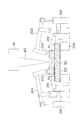
図5は、クランプ装置を説明するための説明図である。 FIG. 5 is an explanatory diagram for explaining the clamp device.
クランプ装置200は、被溶接部材を乗せるワーク支持台205と、ワーク支持台205に乗せられた下板52を固定する補助クランパー201(第2クランパー)と、上板51上から上板を固定する主クランパー202(第1クランパー)を有する。
The
補助クランパー201は、たとえば下板52と上板52とで形状が異なり、下板部分のみ上方からクランプできる位置に、または、上板51と干渉しない位置で、下板52のみ把持して固定できるように設けられている。補助クランパー201は、開閉動作(固定または開放)できるものであれば良い。
The
一方、主クランパー202は、上板51上から下板52と上板51の両方をクランプできる位置に設けられている。主クランパー202は、上板51に当接する部分に電磁石220が設けられている。電磁石220は、主クランパー202のアームとボールベアリング221によって接続され、ある程度自由に動くようになっている。このため、電磁石220は上板51と当接した際に上板51と平行になり確実に上板51を吸着することができる。
On the other hand, the
この電磁石220によって、上板51のみを持ち上げることができる。したがって、主クランパー202は開閉動作の他に、主クランパー202の開閉量を自在に制御するために、主クランパー202はサーボモータ(不図示)によって動作するサーボモータ式のシリンダ210を用いている。これにより電磁石220で上板51を吸着した状態で、上板51と下板52の間に任意の隙間を与えることができる。
Only the
プレ照射の際に作る隙間は、たとえば1〜3mm程度である。この隙間があまり少ないとプレ照射の際に蒸発した亜鉛が逃げづらいため1mm程度が好ましい。一方、隙間があまり大きいと、上板51とした板52の両方に防錆層がある場合にこれら両方の亜鉛メッキを蒸発させることができなくなるためである。これは、たとえばプレ照射を上板51側から行った場合に、上板51がまず加熱され、その輻射熱によって下板52が加熱されることになるが、隙間が大き過ぎる場合下板52が十分に加熱されなくなるおそれがある。このため隙間の最大は3mm程度が好ましい。しかし、加える熱量に応じて下板52まで亜鉛メッキ53を蒸発させるのに十分な熱量の伝わるものであれば、もっと大きな隙間であってもよい。また、下板52にそもそも防錆層がない場合、隙間は1mm以上あればいくら開いていてもよい。
The gap created during pre-irradiation is, for example, about 1 to 3 mm. If this gap is too small, the zinc evaporated during pre-irradiation is difficult to escape, so about 1 mm is preferable. On the other hand, if the gap is too large, it is impossible to evaporate both of these galvanized plates when both the
次に、本実施形態によるレーザ溶接システムの作用を説明する。 Next, the operation of the laser welding system according to the present embodiment will be described.
図6はこのレーザ溶接システムにおける溶接の動作手順を示すフローチャートであり、図7〜10は溶接動作を説明するためクランプ装置200の動作状態を説明する説明図である。この動作手順に従い、制御装置が各部を制御することによって行われる。
FIG. 6 is a flowchart showing an operation procedure of welding in this laser welding system, and FIGS. 7 to 10 are explanatory diagrams for explaining the operation state of the
ここで、被溶接部材である鋼板(上板51、下板52)は、両方とも表裏面に防錆層である亜鉛メッキ53が施されたものである。
Here, the steel plates (the
まず、クランプ装置200の台に下板52をセットし、下板52のみを補助クランパー201で固定する(S1、図7)。
First, the
次に、上板51を下板52の上に乗せて、主クランパー202でいったん軽くクランプする(たとえば、主クランパー202を閉動作させて下板52と上板51が接触する状態)(S2)。
Next, the
この状態から、クランプ装置200の主クランパー202の電磁石220を動作させて、上板51を吸着させ、上板51のみを所定量持ち上げる(S3、図8)。これにより鋼板同士の間に所定の隙間が開く。
From this state, the
続いて、プレ照射のために、加工ヘッド10を溶接点へレーザ光を照射できる位置移動する(S4、図8)。このとき、複数の溶接点がある場合には、それら複数の溶接点へレーザ光を照射できる位置に加工ヘッド10の位置決めする。
Subsequently, for pre-irradiation, the
続いて、レンズを移動させてデフォーカス状態となるように焦点位置を調整するとともに、レーザ発振器に対してレーザ光の照射周波数を下げるように指示する。そして、レーザ光のプレ照射を実行する(S5、図8)。このとき、複数の溶接点がある場合には、それら複数の溶接点すべてへ、レーザ光のプレ照射を実施する。これにより、溶接点における亜鉛メッキが気化して蒸発する。 Subsequently, the lens is moved to adjust the focal position so as to be in a defocused state, and the laser oscillator is instructed to lower the irradiation frequency of the laser light. Then, pre-irradiation with laser light is executed (S5, FIG. 8). At this time, when there are a plurality of welding points, pre-irradiation of laser light is performed on all of the plurality of welding points. Thereby, galvanization in a welding point vaporizes and evaporates.
プレ照射終了後、主クランパー202を完全に閉めて、上板51と下板52が完全に接触させる(S6、図9)。この状態で、溶接のために焦点位置を溶接点に合うようにレンズを移動して調整し、溶接のためのレーザ照射を実行する(S7)。
After the pre-irradiation is completed, the
(実施例)
次に、上記動作手順に沿って実際に溶接した実験例について説明する。
(Example)
Next, an experimental example actually welded along the above operation procedure will be described.
被溶接部材は、厚さ10mmの亜鉛メッキ鋼板(軟鉄板)2枚を使用した。溶接個所は2枚の鋼板を重ねた部分である(継手)。 As a member to be welded, two galvanized steel plates (soft iron plates) having a thickness of 10 mm were used. A welding point is a portion where two steel plates are overlapped (joint).
プレ照射時のレーザ出力:2kW、パスル周波数:20Hz、スポット径:10mmとした。 Laser output during pre-irradiation: 2 kW, pulse frequency: 20 Hz, spot diameter: 10 mm.
溶接時のレーザ出力:4kW、パスルなし(すなわち間欠せずに照射)、スポット径:0.3mmで、プレ照射時のスポット径内に溶接速度4m/minでC字形状を描いた。 A laser output at the time of welding: 4 kW, no pulse (that is, irradiation without intermittent), a spot diameter: 0.3 mm, and a C-shape was drawn at a welding speed of 4 m / min within the spot diameter at the time of pre-irradiation.
以上の条件で、実施例として1〜3mm程度の隙間を明けてプレ照射した後、溶接を行った。また、比較例として隙間を開けずにプレ照射した後、溶接を行った。 Under the above conditions, as an example, after pre-irradiating with a gap of about 1 to 3 mm, welding was performed. Further, as a comparative example, welding was performed after pre-irradiation without opening a gap.
図10は実施例および比較例の溶接後の溶接部分断面を示す模式図である。 FIG. 10 is a schematic diagram showing a cross section of a welded part after welding in Examples and Comparative Examples.
実施例の溶接では、目視検査の結果、溶接ビード表面にポロシティに起因する荒れなどは認められなかった。図10(a)はこの実施例の結果を示す断面模式図である。図示するように、隙間を開けてプレ照射を行ったために溶接前の段階でポロシティの原因となる亜鉛は完全に除去されたため、表面荒れなどが発生しなかったと考えられる。 In the welding of the examples, as a result of visual inspection, no roughness due to porosity was found on the surface of the weld bead. FIG. 10A is a schematic cross-sectional view showing the results of this example. As shown in the figure, it was considered that since the pre-irradiation was performed with a gap, zinc causing porosity was completely removed at the stage before welding, and thus surface roughness did not occur.
一方、比較例では目視の結果、ポロシティに起因する表面荒れが認められた。これは、図10(b)に示すように、プレ照射を行ったものの、隙間がないために亜鉛が完全に除去されず、溶接時にポロシティ70が発生して溶接ビード表面まで出てきて、表面が荒れてしまったと考えられる。
On the other hand, as a result of visual observation in the comparative example, surface roughness due to porosity was observed. As shown in FIG. 10 (b), although pre-irradiation was performed, since there was no gap, zinc was not completely removed, and
したがって、本発明を適用した溶接では、溶接ビードが形成された部分に、ポロシティによる溶接ビード表面の荒れがなく、良好な溶接品質を得ることができ、接合強度も十分なものとなることがわかった。 Therefore, in the welding to which the present invention is applied, it is found that the weld bead surface is not roughened by the porosity at the portion where the weld bead is formed, a good weld quality can be obtained, and the joining strength is sufficient. It was.
以上説明したように、本発明を適用した実施形態および実施例によれば下記のような効果を奏する。 As described above, according to the embodiments and examples to which the present invention is applied, the following effects can be obtained.
本実施形態は、防錆層を持つ鋼板同士の間に隙間を与えて、亜鉛が蒸発する程度の熱量となるようにレーザ光をプレ照射し、その後、鋼板同士を接触させて溶接することとした。これにより、プレ照射により隙間から完全に亜鉛を蒸発させた後、溶接を行うこととなるため亜鉛の蒸発に伴うポロシティの発生を防止することができる。しかも、溶接時には2枚の鋼板を完全に接触させてからレーザ照射するため、不要なゆがみなどが発生せず、溶接品質を低下させるおそれもない。 In the present embodiment, a gap is provided between steel plates having a rust-proof layer, laser light is pre-irradiated so that the amount of heat is such that zinc is evaporated, and then the steel plates are brought into contact with each other for welding. did. Thereby, after zinc is completely evaporated from the gap by pre-irradiation, welding is performed, and therefore generation of porosity due to evaporation of zinc can be prevented. Moreover, since the laser irradiation is performed after the two steel plates are completely brought into contact with each other during welding, unnecessary distortion does not occur, and there is no possibility of reducing the welding quality.
また、プレ照射時の熱量調整は、レーザ光の焦点位置を調整することで鋼板上のスポット径を変えて行うこととしたので、レーザ光による熱量調整と共に、亜鉛を飛ばす範囲を焦点位置調整によって行うことができる。 In addition, the amount of heat during pre-irradiation is adjusted by changing the spot diameter on the steel plate by adjusting the focal position of the laser beam. It can be carried out.
また、溶接を行う部分はプレ照射時のスポット径の範囲内としたので、プレ照射によって亜鉛を飛ばした部分を確実に溶接し、ポロシティの発生を防止することができる。 Further, since the portion to be welded is within the range of the spot diameter at the time of pre-irradiation, the portion from which zinc has been blown off by pre-irradiation can be reliably welded to prevent the occurrence of porosity.
また、複数の溶接点に対しては、隙間を開けた後、複数の溶接点に対してプレ照射を行い、その後隙間を閉めて溶接を行うこととしたので、レーザ溶接装置の特徴の一つである、加工ヘッドを止めた状態からミラーを動かすことでレーザ光を走査して、ロボットの動作を伴うことなく、プレ照射と溶接をそれぞれ実行し得るようになる。これにより、複数の溶接点に対しても、プレ照射と溶接をそれぞれ連続的に効率良く行うことができる。また、プレ照射もレーザ照射によって防錆層を除去しているので、複数の溶接点を連続してプレ照射し防錆層を除去したとしても、その後の溶接動作に至までの時間は非常に少ない。したがって、防錆層除去部分が時間経過によって酸化されることもなく、良好な溶接を行うことが可能である。 In addition, for a plurality of welding points, after a gap is formed, pre-irradiation is performed on the plurality of welding points, and then the gap is closed and welding is performed. The laser beam is scanned by moving the mirror from the state where the machining head is stopped, and pre-irradiation and welding can be executed without the operation of the robot. Thereby, pre-irradiation and welding can be performed continuously and efficiently even at a plurality of welding points. In addition, the pre-irradiation also removes the rust prevention layer by laser irradiation, so even if the pre-irradiation is continuously pre-irradiated at multiple welding points to remove the rust prevention layer, the time until the subsequent welding operation is very long. Few. Therefore, it is possible to perform good welding without the rust-preventing layer removed portion being oxidized over time.
また、クランプ装置に電磁石を設け、下板を別途固定した状態でこの電磁石により上板を吸着して持ち上げることとしたので、容易に隙間を開けることができる。また、サーボモータ式のシリンダ(電動アクチュエータ)によってクランパーを動作させることとしたので、隙間の調整も容易である。 Further, since the electromagnet is provided in the clamp device and the lower plate is separately fixed, the upper plate is attracted and lifted by the electromagnet, so that a gap can be easily formed. Further, since the clamper is operated by a servo motor type cylinder (electric actuator), the adjustment of the gap is easy.
以上本発明を適応した実施形態および実施例を説明したが、本発明はこれらの実施形態および実施例に限定されるものではない。 Although the embodiments and examples to which the present invention is applied have been described above, the present invention is not limited to these embodiments and examples.
たとえば、上述した実施形態では、クランプ装置において、上板を吸着させるために電磁石を用いた。しかし、電磁石に代えて、たとえば、真空吸着装置を用いてもよい。図11は、真空吸着装置を用いたクランプ装置の一例を示す図面である。このクランプ装置300では、主クランパー202に真空吸着カップ301を取り付けている。図示しない真空ポンプを作動させることで上板51を吸着できるようにしている。主クランパー202は、前述したクランプ装置200と同様にサーボモータによって開閉する。したがって、上板51と下板52の間の間隔調整を行うことができる。また、このクランプ装置300では、補助クランパーを設けていない。これは上板51を吸着する際に、真空吸着としているため、上板51吸着時に下板52が一緒に上がってしまう心配がないためである。このため、下板52のみをクランプすることができないような形状の場合に、特に有効である。これはまた、下板52を個別に固定する必要が無くなるので、クランプ装置を簡略化することができる。もちろん、下板52の安定のためなどに、必要であれば補助クランパーを設けても差し支えない。
For example, in the above-described embodiment, an electromagnet is used in the clamp device to attract the upper plate. However, instead of the electromagnet, for example, a vacuum suction device may be used. FIG. 11 is a drawing showing an example of a clamping device using a vacuum suction device. In this
このクランプ装置300を用いた場合の溶接動作は、下板52のクランプ動作が省略され、上板51の吸着が真空吸着に変わるのみで、その他の動作は、上述した実施形態と同様である。また溶接動作における作用効果も同じであるので説明は省略する。
The welding operation using this
また、上述した実施形態では、亜鉛メッキが形成された鋼板同士をレーザ溶接することを例に説明した。しかし、接合対象は、2枚の鋼板のうち1枚が防錆処理されていない裸材であってもよい。さらに、鋼板表面を覆う防錆層も亜鉛メッキに限定されず、アルミニウムメッキまたはクロムメッキであってもよく、鋼板表面を覆う種々の防錆層に対しても有効である。 Moreover, in embodiment mentioned above, it demonstrated as an example laser welding the steel plates in which galvanization was formed. However, the joining target may be a bare material in which one of the two steel plates is not rust-proofed. Furthermore, the rust preventive layer covering the steel plate surface is not limited to galvanizing, and may be aluminum plating or chrome plating, and is effective for various rust preventive layers covering the steel plate surface.
また、上述した実施形態では、亜鉛メッキが形成された2枚鋼板をレーザ溶接することを例に説明した。しかし、溶接対象は2枚の鋼板とは限らず、溶接部分が3枚以上となる場合でも適用可能である。すなわち、3枚以上となる溶接部分のそれぞれに対して、防錆層がある部分に隙間を開いてプレ照射を実行し、その後、隙間を閉じて溶接のためのレーザ照射を行えばよい。 Moreover, in embodiment mentioned above, it demonstrated as an example laser welding the 2 sheet steel plate in which galvanization was formed. However, the object to be welded is not limited to two steel plates, and is applicable even when there are three or more welded portions. That is, with respect to each of the three or more welded portions, a pre-irradiation is performed by opening a gap in a portion where the rust preventive layer is present, and thereafter, the gap is closed and laser irradiation for welding is performed.
1 レーザ溶接システム、
10 加工ヘッド、
11a〜11d レンズ(レーザ強度変更手段)、
20 ロボット、
30 レーザ発振器(レーザ強度変更手段)、
40 制御装置(制御手段)、
200、300 クランプ装置、
201 補助クランパー(第2クランパー)、
202 主クランパー(第1クランパー)、
205 ワーク支持台、
210 シリンダ、
220 電磁石、
301 真空吸着カップ。
1 Laser welding system,
10 processing head,
11a to 11d lenses (laser intensity changing means),
20 robots,
30 Laser oscillator (laser intensity changing means),
40 control device (control means),
200, 300 clamping device,
201 Auxiliary clamper (second clamper),
202 Main clamper (first clamper),
205 workpiece support,
210 cylinders,
220 electromagnet,
301 Vacuum suction cup.
Claims (9)
前記少なくとも2枚の鋼板の防錆層がある面と他の鋼板との間に隙間を空ける段階と、
前記少なくとも2枚の鋼板のうちいずれか一方の鋼板へ、前記防錆層を蒸発させる熱量で、かつ溶接に至らない熱量となるレーザ光をプレ照射する段階と、
前記プレ照射する段階後、前記隙間を閉じて前記少なくとも2枚の鋼板を接触させる段階と、
前記プレ照射した部分に前記溶接に必要な熱量のレーザ光を照射して前記溶接する段階と、を有することを特徴とするレーザ溶接方法。 At least one is a laser welding method of at least two steel plates having a rust prevention layer,
A step of opening a gap between the surface of the at least two steel plates having a rust prevention layer and another steel plate;
Pre-irradiating a laser beam having a heat amount for evaporating the rust preventive layer and a heat amount that does not lead to welding to any one of the at least two steel plates;
After the pre-irradiation step, closing the gap and contacting the at least two steel plates;
Irradiating the pre-irradiated portion with a laser beam having a heat amount necessary for the welding to perform the welding.
前記複数の溶接点に対して前記プレ照射を行った後、前記隙間を閉めて前記複数の溶接点へ前記溶接すする段階を行うことを特徴とする請求項1〜3のいずれか一つに記載のレーザ溶接方法。 After the step of opening the gap, performing the pre-irradiation to a plurality of welding points,
4. The method according to claim 1, wherein after performing the pre-irradiation on the plurality of welding points, the step of closing the gaps and performing the welding to the plurality of welding points is performed. The laser welding method as described.
レーザ光の照射する強度を変更するレーザ強度変更手段を備えたレーザ照射手段と、
少なくとも2枚の鋼板を重ね合わせて鋼板同士の間の隙間を調整自在なクランプ手段と、
前記少なくとも2枚の鋼板の間に隙間を空けるように前記クランプ手段を制御し、前記少なくとも2枚の鋼板へ、前記防錆層を蒸発させる熱量でかつ溶接に至らない熱量となるレーザ光をプレ照射させるように前記レーザ照射手段を制御し、前記プレ照射の後、前記隙間を閉じて前記少なくとも2枚の鋼板を接触させるように前記クランプ手段を制御し、さらに前記プレ照射した部分に前記溶接に必要な熱量となるレーザ光を照射するように前記レーザ照射手段を制御する制御手段と、
を有することを特徴とするレーザ溶接システム。 At least one is a laser welding system for welding at least two steel plates having a rust prevention layer,
Laser irradiation means comprising laser intensity changing means for changing the intensity of laser light irradiation;
Clamping means capable of adjusting the gap between the steel plates by overlapping at least two steel plates;
The clamping means is controlled so as to leave a gap between the at least two steel plates, and a laser beam having a heat amount for evaporating the anticorrosive layer and a heat amount that does not lead to welding is applied to the at least two steel plates. The laser irradiation means is controlled to irradiate, and after the pre-irradiation, the gap means is closed and the clamp means is controlled to contact the at least two steel plates, and the weld is applied to the pre-irradiated portion. Control means for controlling the laser irradiation means so as to irradiate a laser beam having a heat amount necessary for
A laser welding system comprising:
前記少なくとも2枚の鋼板である第1の鋼板と第2の鋼板を挟む第1クランパーと、
前記第1クランパーの開閉量を制御するサーボモータ式の第1クランパー駆動源と、
前記第2の鋼板をクランプする第2クランパーと、
前記第2クランパーを開閉する第2クランパー駆動源と、
前記第1クランパーに取り付けられ前記第1の鋼板を吸着離脱自在な電磁石と、
を備え、
前記制御手段は、前記プレ照射の際には、前記電磁石により前記第1の鋼板を吸着した状態で前記第1の鋼板と前記第2の鋼板の間に前記隙間を作るように第1クランパー駆動源を制御することを特徴とする請求項5に記載のレーザ溶接システム。 The clamping means includes
A first clamper sandwiching the first steel plate and the second steel plate which are the at least two steel plates; and
A servo motor type first clamper drive source for controlling the opening / closing amount of the first clamper;
A second clamper for clamping the second steel plate;
A second clamper drive source for opening and closing the second clamper;
An electromagnet attached to the first clamper and capable of adsorbing and detaching the first steel plate;
With
In the pre-irradiation, the control means drives the first clamper so as to create the gap between the first steel plate and the second steel plate while the first steel plate is attracted by the electromagnet. 6. The laser welding system according to claim 5, wherein the source is controlled.
前記少なくとも2枚の鋼板である第1の鋼板と第2の鋼板を挟む第1クランパーと、
前記第1クランパーの開閉量を制御するサーボモータ式の第1クランパー駆動源と、
前記第1クランパーに取り付けられ前記第1の鋼板を吸着離脱自在な真空吸着手段と、
を備え、
前記制御手段は、前記プレ照射の際には、前記真空吸着手段により前記第1の鋼板を吸着した状態で前記第1の鋼板と前記第2の鋼板の間に前記隙間を作るように第1クランパー駆動源を制御することを特徴とする請求項5に記載のレーザ溶接システム。 The clamping means includes
A first clamper sandwiching the first steel plate and the second steel plate which are the at least two steel plates; and
A servo motor type first clamper drive source for controlling the opening / closing amount of the first clamper;
A vacuum suction means attached to the first clamper and capable of sucking and detaching the first steel plate;
With
In the pre-irradiation, the control means is configured to create the gap between the first steel sheet and the second steel sheet in a state where the first steel sheet is adsorbed by the vacuum suction means. 6. The laser welding system according to claim 5, wherein the clamper driving source is controlled.
前記制御手段は、前記プレ照射の際には前記焦点調整手段により照射するレーザ光の焦点を、レーザ照射面である鋼板面からずらしてレーザ光のスポット径を広げることにより、前記防錆層を蒸発させる熱量で、かつ前記溶接に至らない熱量となるように制御することを特徴とする請求項5〜7のいずれか一つに記載のレーザ溶接システム。 The laser intensity changing means is a focus adjusting means for changing the focal position of the laser beam,
The control means shifts the focal point of the laser light irradiated by the focus adjusting means during the pre-irradiation from the steel plate surface that is the laser irradiation surface to widen the spot diameter of the laser light, thereby to The laser welding system according to any one of claims 5 to 7, wherein the amount of heat to be evaporated is controlled so as to be a heat amount that does not lead to the welding.
Priority Applications (1)
| Application Number | Priority Date | Filing Date | Title |
|---|---|---|---|
| JP2007329023A JP2009148794A (en) | 2007-12-20 | 2007-12-20 | Laser welding method and laser welding system |
Applications Claiming Priority (1)
| Application Number | Priority Date | Filing Date | Title |
|---|---|---|---|
| JP2007329023A JP2009148794A (en) | 2007-12-20 | 2007-12-20 | Laser welding method and laser welding system |
Publications (1)
| Publication Number | Publication Date |
|---|---|
| JP2009148794A true JP2009148794A (en) | 2009-07-09 |
Family
ID=40918601
Family Applications (1)
| Application Number | Title | Priority Date | Filing Date |
|---|---|---|---|
| JP2007329023A Pending JP2009148794A (en) | 2007-12-20 | 2007-12-20 | Laser welding method and laser welding system |
Country Status (1)
| Country | Link |
|---|---|
| JP (1) | JP2009148794A (en) |
Cited By (3)
| Publication number | Priority date | Publication date | Assignee | Title |
|---|---|---|---|---|
| CN103418982A (en) * | 2013-08-27 | 2013-12-04 | 中国重汽集团济南动力有限公司 | Locating pin clamp for welding, and operating method thereof |
| CN104924004A (en) * | 2014-03-19 | 2015-09-23 | 上海强精金属制品有限公司 | Quick clamping mechanism for induction cooker side wall welding |
| KR102158855B1 (en) * | 2019-11-01 | 2020-09-22 | 엠디티 주식회사 | Laser welding apparatus and method |
-
2007
- 2007-12-20 JP JP2007329023A patent/JP2009148794A/en active Pending
Cited By (3)
| Publication number | Priority date | Publication date | Assignee | Title |
|---|---|---|---|---|
| CN103418982A (en) * | 2013-08-27 | 2013-12-04 | 中国重汽集团济南动力有限公司 | Locating pin clamp for welding, and operating method thereof |
| CN104924004A (en) * | 2014-03-19 | 2015-09-23 | 上海强精金属制品有限公司 | Quick clamping mechanism for induction cooker side wall welding |
| KR102158855B1 (en) * | 2019-11-01 | 2020-09-22 | 엠디티 주식회사 | Laser welding apparatus and method |
Similar Documents
| Publication | Publication Date | Title |
|---|---|---|
| JP6518945B2 (en) | Laser welding method and laser welding apparatus | |
| US9737960B2 (en) | Laser-based lap welding of sheet metal components using laser induced protuberances to control gap | |
| JP4867599B2 (en) | Laser welding method and apparatus | |
| JP2005515895A (en) | Method and apparatus for increasing welding speed for high aspect ratio welds | |
| JP2014018804A (en) | One side welding method | |
| JP2008264793A (en) | Laser welding method for superimposed workpiece | |
| JP2006021217A5 (en) | ||
| JP6299136B2 (en) | Laser welding method and laser welding apparatus for steel sheet | |
| TW200924895A (en) | Surface crack sealing method | |
| JP5365729B2 (en) | Laser welding method and welded joint | |
| JP2009154184A (en) | Laser beam welding method and welded joined body | |
| JP2009148794A (en) | Laser welding method and laser welding system | |
| JP2012206145A (en) | Hot wire laser welding method and apparatus | |
| JP4915315B2 (en) | Laser welding method and laser welding apparatus | |
| JP4210857B2 (en) | Laser machining method for plated plate | |
| JP6720604B2 (en) | Laser welding machine | |
| KR20140045605A (en) | Laser welding device and welding method for galvanized steel sheet | |
| JP4386431B2 (en) | Laser welding method | |
| JP2011115836A (en) | Method of laser welding metal plated plate | |
| JPS6163387A (en) | Laser beam machine | |
| KR20120077094A (en) | Welding method for coating steel sheets | |
| JP2017209700A (en) | Joining method of metal plate | |
| JPH02268991A (en) | Laser welding method for galvanized steel sheet | |
| JP7185436B2 (en) | Laser processing method | |
| JP2018069258A (en) | Laser welding method and laser welding equipment |