JP2005515895A - Method and apparatus for increasing welding speed for high aspect ratio welds - Google Patents
Method and apparatus for increasing welding speed for high aspect ratio welds Download PDFInfo
- Publication number
- JP2005515895A JP2005515895A JP2003562457A JP2003562457A JP2005515895A JP 2005515895 A JP2005515895 A JP 2005515895A JP 2003562457 A JP2003562457 A JP 2003562457A JP 2003562457 A JP2003562457 A JP 2003562457A JP 2005515895 A JP2005515895 A JP 2005515895A
- Authority
- JP
- Japan
- Prior art keywords
- welding wire
- opening
- laser beam
- aspect ratio
- laser
- Prior art date
- Legal status (The legal status is an assumption and is not a legal conclusion. Google has not performed a legal analysis and makes no representation as to the accuracy of the status listed.)
- Pending
Links
Images


Classifications
-
- F—MECHANICAL ENGINEERING; LIGHTING; HEATING; WEAPONS; BLASTING
- F01—MACHINES OR ENGINES IN GENERAL; ENGINE PLANTS IN GENERAL; STEAM ENGINES
- F01D—NON-POSITIVE DISPLACEMENT MACHINES OR ENGINES, e.g. STEAM TURBINES
- F01D5/00—Blades; Blade-carrying members; Heating, heat-insulating, cooling or antivibration means on the blades or the members
- F01D5/005—Repairing methods or devices
-
- B—PERFORMING OPERATIONS; TRANSPORTING
- B23—MACHINE TOOLS; METAL-WORKING NOT OTHERWISE PROVIDED FOR
- B23K—SOLDERING OR UNSOLDERING; WELDING; CLADDING OR PLATING BY SOLDERING OR WELDING; CUTTING BY APPLYING HEAT LOCALLY, e.g. FLAME CUTTING; WORKING BY LASER BEAM
- B23K26/00—Working by laser beam, e.g. welding, cutting or boring
- B23K26/20—Bonding
- B23K26/21—Bonding by welding
-
- B—PERFORMING OPERATIONS; TRANSPORTING
- B23—MACHINE TOOLS; METAL-WORKING NOT OTHERWISE PROVIDED FOR
- B23K—SOLDERING OR UNSOLDERING; WELDING; CLADDING OR PLATING BY SOLDERING OR WELDING; CUTTING BY APPLYING HEAT LOCALLY, e.g. FLAME CUTTING; WORKING BY LASER BEAM
- B23K1/00—Soldering, e.g. brazing, or unsoldering
- B23K1/0008—Soldering, e.g. brazing, or unsoldering specially adapted for particular articles or work
- B23K1/0018—Brazing of turbine parts
-
- B—PERFORMING OPERATIONS; TRANSPORTING
- B23—MACHINE TOOLS; METAL-WORKING NOT OTHERWISE PROVIDED FOR
- B23K—SOLDERING OR UNSOLDERING; WELDING; CLADDING OR PLATING BY SOLDERING OR WELDING; CUTTING BY APPLYING HEAT LOCALLY, e.g. FLAME CUTTING; WORKING BY LASER BEAM
- B23K1/00—Soldering, e.g. brazing, or unsoldering
- B23K1/005—Soldering by means of radiant energy
-
- B—PERFORMING OPERATIONS; TRANSPORTING
- B23—MACHINE TOOLS; METAL-WORKING NOT OTHERWISE PROVIDED FOR
- B23K—SOLDERING OR UNSOLDERING; WELDING; CLADDING OR PLATING BY SOLDERING OR WELDING; CUTTING BY APPLYING HEAT LOCALLY, e.g. FLAME CUTTING; WORKING BY LASER BEAM
- B23K26/00—Working by laser beam, e.g. welding, cutting or boring
- B23K26/20—Bonding
- B23K26/21—Bonding by welding
- B23K26/211—Bonding by welding with interposition of special material to facilitate connection of the parts
-
- B—PERFORMING OPERATIONS; TRANSPORTING
- B23—MACHINE TOOLS; METAL-WORKING NOT OTHERWISE PROVIDED FOR
- B23K—SOLDERING OR UNSOLDERING; WELDING; CLADDING OR PLATING BY SOLDERING OR WELDING; CUTTING BY APPLYING HEAT LOCALLY, e.g. FLAME CUTTING; WORKING BY LASER BEAM
- B23K26/00—Working by laser beam, e.g. welding, cutting or boring
- B23K26/20—Bonding
- B23K26/21—Bonding by welding
- B23K26/24—Seam welding
- B23K26/26—Seam welding of rectilinear seams
-
- B—PERFORMING OPERATIONS; TRANSPORTING
- B23—MACHINE TOOLS; METAL-WORKING NOT OTHERWISE PROVIDED FOR
- B23K—SOLDERING OR UNSOLDERING; WELDING; CLADDING OR PLATING BY SOLDERING OR WELDING; CUTTING BY APPLYING HEAT LOCALLY, e.g. FLAME CUTTING; WORKING BY LASER BEAM
- B23K26/00—Working by laser beam, e.g. welding, cutting or boring
- B23K26/34—Laser welding for purposes other than joining
- B23K26/342—Build-up welding
-
- B—PERFORMING OPERATIONS; TRANSPORTING
- B23—MACHINE TOOLS; METAL-WORKING NOT OTHERWISE PROVIDED FOR
- B23K—SOLDERING OR UNSOLDERING; WELDING; CLADDING OR PLATING BY SOLDERING OR WELDING; CUTTING BY APPLYING HEAT LOCALLY, e.g. FLAME CUTTING; WORKING BY LASER BEAM
- B23K26/00—Working by laser beam, e.g. welding, cutting or boring
- B23K26/60—Preliminary treatment
-
- B—PERFORMING OPERATIONS; TRANSPORTING
- B23—MACHINE TOOLS; METAL-WORKING NOT OTHERWISE PROVIDED FOR
- B23P—METAL-WORKING NOT OTHERWISE PROVIDED FOR; COMBINED OPERATIONS; UNIVERSAL MACHINE TOOLS
- B23P6/00—Restoring or reconditioning objects
- B23P6/002—Repairing turbine components, e.g. moving or stationary blades, rotors
- B23P6/005—Repairing turbine components, e.g. moving or stationary blades, rotors using only replacement pieces of a particular form
-
- B—PERFORMING OPERATIONS; TRANSPORTING
- B23—MACHINE TOOLS; METAL-WORKING NOT OTHERWISE PROVIDED FOR
- B23K—SOLDERING OR UNSOLDERING; WELDING; CLADDING OR PLATING BY SOLDERING OR WELDING; CUTTING BY APPLYING HEAT LOCALLY, e.g. FLAME CUTTING; WORKING BY LASER BEAM
- B23K2101/00—Articles made by soldering, welding or cutting
- B23K2101/001—Turbines
-
- F—MECHANICAL ENGINEERING; LIGHTING; HEATING; WEAPONS; BLASTING
- F05—INDEXING SCHEMES RELATING TO ENGINES OR PUMPS IN VARIOUS SUBCLASSES OF CLASSES F01-F04
- F05D—INDEXING SCHEME FOR ASPECTS RELATING TO NON-POSITIVE-DISPLACEMENT MACHINES OR ENGINES, GAS-TURBINES OR JET-PROPULSION PLANTS
- F05D2200/00—Mathematical features
- F05D2200/20—Special functions
- F05D2200/23—Logarithm
-
- F—MECHANICAL ENGINEERING; LIGHTING; HEATING; WEAPONS; BLASTING
- F05—INDEXING SCHEMES RELATING TO ENGINES OR PUMPS IN VARIOUS SUBCLASSES OF CLASSES F01-F04
- F05D—INDEXING SCHEME FOR ASPECTS RELATING TO NON-POSITIVE-DISPLACEMENT MACHINES OR ENGINES, GAS-TURBINES OR JET-PROPULSION PLANTS
- F05D2230/00—Manufacture
- F05D2230/20—Manufacture essentially without removing material
- F05D2230/23—Manufacture essentially without removing material by permanently joining parts together
- F05D2230/232—Manufacture essentially without removing material by permanently joining parts together by welding
- F05D2230/235—TIG or MIG welding
-
- F—MECHANICAL ENGINEERING; LIGHTING; HEATING; WEAPONS; BLASTING
- F05—INDEXING SCHEMES RELATING TO ENGINES OR PUMPS IN VARIOUS SUBCLASSES OF CLASSES F01-F04
- F05D—INDEXING SCHEME FOR ASPECTS RELATING TO NON-POSITIVE-DISPLACEMENT MACHINES OR ENGINES, GAS-TURBINES OR JET-PROPULSION PLANTS
- F05D2230/00—Manufacture
- F05D2230/80—Repairing, retrofitting or upgrading methods
Abstract
【課題】 それぞれ第一及び第二の材料を含む第一の加工部品(20)を第二の加工部品(20)に溶接するために溶接ワイヤ(22)をレーザ処理する方法を提供する。
【解決手段】 本方法は、加工部品で画成される開口(29)の上方に溶接ワイヤの先端(27)を配置する段階を含む。先端は、開口(29)の幅を覆いかつ各加工部品(20,20)の一部を覆うように延在する。溶接ワイヤは予熱され、レーザビーム(18)を先端に当てることによって溶融される。先端がレーザビーム(18)の下方に位置した状態でレーザビーム(18)を開口(29)の長さに沿って前進させて、加工部品(20,20)間に高アスペクト比溶接部(37)を形成する。高アスペクト比溶接部(37)は、約2以上のアスペクト比を有する。溶接ワイヤ(22)が予熱されるので、溶接ワイヤ(22)を溶融するためにレーザビーム(18)に必要なエネルギー及び時間が低減される。PROBLEM TO BE SOLVED: To provide a method of laser processing a welding wire (22) for welding a first workpiece (20) containing first and second materials, respectively, to a second workpiece (20).
The method includes placing a welding wire tip (27) over an opening (29) defined by a workpiece. The tip extends to cover the width of the opening (29) and part of each workpiece (20, 20). The welding wire is preheated and melted by applying a laser beam (18) to the tip. With the tip positioned below the laser beam (18), the laser beam (18) is advanced along the length of the opening (29) to provide a high aspect ratio weld (37) between the workpieces (20, 20). ). The high aspect ratio weld (37) has an aspect ratio of about 2 or greater. Since the welding wire (22) is preheated, the energy and time required for the laser beam (18) to melt the welding wire (22) is reduced.
Description
本発明は、高アスペクト比(溶込み深さと溶込み幅との比が高い)溶接部の溶接速度を向上させる方法及び装置に関し、さらに具体的には、溶接ワイヤを用いて同種又は異種の割れ感受性加工部品間に形成される高アスペクト比溶接部の溶接速度を高める方法及び装置に関する。 The present invention relates to a method and an apparatus for improving the welding speed of a high aspect ratio (the ratio of penetration depth and penetration width is high) weld, and more specifically, cracks of the same type or different types using a welding wire. The present invention relates to a method and apparatus for increasing the welding speed of high aspect ratio welds formed between sensitive workpieces.
伝統的な多くの溶接法では、ワイヤ供給装置を用いて溶接ワイヤを供給する。しかし、割れ感受性材料が関与する用途では、こうした方法は通例過度の熱を加え、不要な欠陥を招くことになる。 In many traditional welding methods, a welding wire is supplied using a wire supply device. However, in applications involving crack-sensitive materials, these methods typically add excessive heat and lead to unwanted defects.
他の方法では、ワイヤは補助供給ワイヤ(タングステン不活性ガス法、つまりTIG法)である。しかし、こうした方法では、要する時間が長くなる。 In another method, the wire is an auxiliary supply wire (tungsten inert gas method, or TIG method). However, this method increases the time required.
欠陥形成を最小にするために用いられる現在の肉盛プロセスでは、割れ感受性合金は、全肉盛プロセスを通して高温に維持される。しかし、ガスタービン翼形部(例えばGTD111)の先端を再生する場合、このプロセスは、高温で数時間を要しかねない。さらに、これは手動プロセスであり、作業員に優しい環境とはいえない。 In current build-up processes used to minimize defect formation, crack sensitive alloys are maintained at high temperatures throughout the entire build-up process. However, when regenerating the tip of a gas turbine airfoil (eg, GTD 111), this process can take several hours at high temperatures. Furthermore, this is a manual process and is not an operator friendly environment.
IN738のような他の材料では、部品が高温に付される時間が長くなりすぎないように低温と高温の間の温度サイクルが繰り返され、欠陥及び部品の変形を最小限にする。しかし、かかる繰返しプロセスでは、所要の肉盛ビルドアップを得るのに要する処理時間が長くなる。 For other materials, such as IN738, the temperature cycle between low and high temperatures is repeated so that the time that the part is subjected to high temperatures is not too long, minimizing defects and component deformation. However, such an iterative process increases the processing time required to obtain the required build-up buildup.
ある従来技術の溶接プロセスではレーザ溶接法が用いられる。例えば、British Shipbuildersに譲渡された米国特許第4634832号(Martyr)は、溶接すべきプレートの隣接する壁をレーザ誘起プラズマを用いて溶接して突合せ溶接部又はT形溶接部を形成する。さらに具体的には、Martyrのプロセスは、レーザビームをビームインタセプタ材料に集束させてプラズマを形成する。プラズマのエネルギーが壁に移動して表面を溶融させ2枚のプレートが溶接されるように、ガスの供給によってプラズマを定位置に保つ。この高エネルギーレーザ溶接プロセスは高アスペクト比溶接部の形成に使用できるが、プラズマから溶接される割れ感受性材料に過度の熱が移動するだけでなく、割れ感受性材料にビームインタセプタ材料が埋め込まれてしまうので、割れ感受性材料の溶接には不適当である。過度の熱と埋め込みはいずれも欠陥及び割れの原因となる。 One prior art welding process uses laser welding. For example, U.S. Pat. No. 4,634,832 (Martyr) assigned to British Shipbuilders welds adjacent walls of a plate to be welded using laser-induced plasma to form a butt weld or a T-shaped weld. More specifically, the Martyr process focuses a laser beam onto a beam interceptor material to form a plasma. The plasma is kept in place by the gas supply so that the energy of the plasma moves to the wall to melt the surface and weld the two plates. This high energy laser welding process can be used to form high aspect ratio welds, but it not only transfers excessive heat from the plasma to the crack sensitive material being welded, but also embeds the beam interceptor material in the crack sensitive material. Therefore, it is unsuitable for welding crack-sensitive materials. Excessive heat and embedding both cause defects and cracks.
Westinghause Electric社に譲渡された米国特許第4737612号(Bruck他)では、溶加材を使用せずにレーザキーホール溶接を形成する。このプロセスは、レーザ(約2〜5百万ワット/cm2の出力密度を有する)から2つの隣接する割れ感受性材料へのエネルギー移動によって材料に割れを引き起こすので、割れ感受性材料には望ましくない。Bruck他はさらに、接合すべき対向表面の側部に沿ってレーザを通し、生じた金属溶融池内に抵抗加熱溶接ワイヤを通すことによってレーザ伝導形溶接部を形成することを開示している。この後者のプロセスも、以下の理由により、割れ感受性材料用及び本発明の目的には望ましくない。第一に、2つの隣接する割れ感受性部品の壁にレーザビームを向けて溶融池を形成することは、これら部品に過度の熱を移して割れ感受性材料に割れその他の欠陥を生じさせることになる。さらに、Bruck他は、伝導形溶接部を形成している。当業者に公知の通り、伝導形溶接部は深さ対幅比が低く、一般に溶接部に沿って変形を生じる。伝導形溶接部の典型的なアスペクト比は1以下である。このように、Bruck他の後者の方法は、本発明の望ましい高アスペクト比を形成しない。 In US Pat. No. 4,737,612 (Bruck et al.) Assigned to Westinghouse Electric, laser keyhole welding is formed without the use of filler material. This process is undesirable for crack sensitive materials as it causes the material to crack by energy transfer from a laser (having a power density of about 2-5 million watts / cm 2 ) to two adjacent crack sensitive materials. Bruck et al. Further discloses forming a laser-conducting weld by passing a laser along the sides of the opposing surfaces to be joined and a resistance heating weld wire through the resulting molten metal pool. This latter process is also undesirable for crack sensitive materials and for the purposes of the present invention for the following reasons. First, directing the laser beam to the walls of two adjacent crack-sensitive parts forms a weld pool that transfers excessive heat to these parts, causing cracks and other defects in the crack-sensitive material. . Further, Bruck et al. Form a conductive weld. As known to those skilled in the art, conductive welds have a low depth to width ratio and generally deform along the weld. A typical aspect ratio of a conductive weld is 1 or less. Thus, the latter method of Brook et al. Does not form the desirable high aspect ratio of the present invention.
別の従来技術のレーザ溶接プロセスが、Westinghouse Electric社に譲渡された米国特許第4803334号(Burke他)に開示されている。Burke他は、2つの突合せ金属母材複合材部品をその交差部を横断するようにレーザビームを搖動させることによって接合する浅い金属溶融池を用いて伝導形溶接部を形成している。予熱した溶接ワイヤを溶融池内に供給して、溶接部に溶加材が付加される。2つの隣接する割れ感受性部品の壁にレーザビームを向けて溶融池を形成することは、これらの部品に過度の熱を移入して割れ感受性材料内に割れその他の欠陥を生じさせるので、このプロセスは、Bruck他のプロセスと同様、割れ感受性材料には望ましくない。さらに、伝導形溶接部は低アスペクト比を有し、変形を生じ易い。 Another prior art laser welding process is disclosed in US Pat. No. 4,803,334 (Burke et al.) Assigned to Westinghouse Electric. Burke et al. Form a conductive weld using a shallow metal weld pool that joins two butt metal matrix composite parts by peristating a laser beam across the intersection. A preheated welding wire is supplied into the molten pool, and a filler metal is added to the weld. This process is accomplished by directing a laser beam to the walls of two adjacent crack-sensitive components to transfer excessive heat to these components, causing cracks and other defects in the crack-sensitive material. Is undesirable for crack-sensitive materials, as in the Bruck et al. Process. Further, the conductive weld has a low aspect ratio and is prone to deformation.
本願出願人に譲渡された米国特許第5958261号(Offer他)には、高アスペクト比溶接部を形成するためのアーク又はレーザ溶接プロセスが記載されており、該プロセスでは、加工品表面の上方に延在しかつ2つの対向する側壁で画成される開先内に溶接ワイヤが供給される。溶接ワイヤの先端はアーク及び/又は過熱溶接パドル(ワイヤの目標位置に応じて)によって溶融され、開先は継目を横断する搖動を必要としないほど十分に狭いのが好ましいが、発散アークの加工部品への投影面積が比較的細いワイヤへの投影面積よりも数倍大きいため、残りのアーク熱は、溶接ワイヤに対してなく主に加工部品に直接に移入される。そのため、明示されているように、Offer他の方法は、基材への熱移動のため割れ感受性基材での使用は望ましくない。
そこで、同種及び異種の割れ感受性基材の接合に使用することができる高アスペクト比溶接部を形成するためのワイヤ供給装置を用いたレーザ溶接プロセスを開発することが望ましい。 Thus, it is desirable to develop a laser welding process using a wire feeder to form high aspect ratio welds that can be used to join similar and dissimilar crack sensitive substrates.
本発明の第一の実施形態では、第一の加工部品を第二の加工部品に溶接するため溶接ワイヤをレーザ処理する方法を開示する。第一及び第二の加工部品はそれぞれ第一及び第二の材料を含む。 In a first embodiment of the present invention, a method for laser processing a welding wire to weld a first workpiece to a second workpiece is disclosed. The first and second workpieces include first and second materials, respectively.
溶接ワイヤの先端は、第一の加工部品と第二の加工部品とで画成される開口の上方に配置される。先端は、開口の幅及び第一の加工部品の一部と第二の加工部品の一部とを覆うように延在する。 The tip of the welding wire is disposed above the opening defined by the first processed part and the second processed part. The tip extends to cover the width of the opening and part of the first workpiece and part of the second workpiece.
溶接ワイヤは予熱される。溶接ワイヤの先端にレーザビームを当てて、溶接ワイヤを溶融する。溶接ワイヤの先端をレーザビームの下方に配置した状態で、開口の長さに沿ってレーザビームを前進させて、第一及び第二の加工部品間に高アスペクト比溶接部を形成する。高アスペクト比溶接部は約2以上のアスペクト比を有する。 The welding wire is preheated. A laser beam is applied to the tip of the welding wire to melt the welding wire. With the welding wire tip positioned below the laser beam, the laser beam is advanced along the length of the opening to form a high aspect ratio weld between the first and second workpieces. The high aspect ratio weld has an aspect ratio of about 2 or greater.
本発明の第二の実施形態では、開口を画成する加工部品の第一の加工部品を第二の加工部品にレーザ溶接するための装置を開示する。 In a second embodiment of the present invention, an apparatus for laser welding a first workpiece of a workpiece defining an opening to a second workpiece is disclosed.
溶接ワイヤは、開口の幅を超える直径を有する。ワイヤ供給装置は、溶接ワイヤを連続的に供給するように構成される。ガイドは、開口の幅及び第一の加工部品の一部と第二の加工部品の一部とを覆うように溶接ワイヤの先端を開口の上方の位置に導くように構成される。 The welding wire has a diameter that exceeds the width of the opening. The wire supply device is configured to continuously supply the welding wire. The guide is configured to guide the tip of the welding wire to a position above the opening so as to cover the width of the opening and a portion of the first workpiece and a portion of the second workpiece.
レーザは、溶接ワイヤの先端にレーザビームを当てて第一及び第二の加工部品間に高アスペクト比溶接部を形成するように構成される。高アスペクト比溶接部は約2以上のアスペクト比を有する。電源は、溶接ワイヤに電流を供給するように構成される。 The laser is configured to apply a laser beam to the tip of the welding wire to form a high aspect ratio weld between the first and second workpieces. The high aspect ratio weld has an aspect ratio of about 2 or greater. The power source is configured to supply current to the welding wire.
本発明は、溶接ワイヤをレーザ処理する方法を含む。本発明は、同種及び異種の割れ感受性加工部品の対向する側壁間に高アスペクト比溶接部を形成するための溶接用途において特に有用である。ただし、本発明は、肉盛形状にも有益に適用できる。 The present invention includes a method of laser processing a welding wire. The present invention is particularly useful in welding applications for forming high aspect ratio welds between opposing sidewalls of homogeneous and dissimilar crack sensitive workpieces. However, the present invention can be beneficially applied to a built-up shape.
ここで図1を参照すると、肉盛システム10が示されている。肉盛システム10はレーザ12を備える。例示的なレーザ12は様々な出力レベルで動作できるCW Nd:YAGレーザである。光ファイバケーブル14の一端はレーザ12に固定され、他端は光ファイバ結合器16に固定される。光ファイバ結合器16は目的のターゲットにレーザビーム18を集束させるための光学系を備える。
Referring now to FIG. 1, a build-
レーザビーム18は基材20に向けられ、その基材に対してワイヤ22が本願の肉盛又は溶接プロセスによって流れ込む。
The
本願では、基材20として、GTD111、GTD222及びIN738のような割れ感受性合金基材が想定され、これらの材料は長時間高温に曝されると変形及び割れを生じ易い。無論、本願の装置及び方法はその他様々な基材にも適用できる。
In the present application, a crack-sensitive alloy substrate such as GTD111, GTD222, and IN738 is assumed as the
ワイヤ22は、細長いチューブ26を通してワイヤを導くワイヤ供給装置24によって基材20に供給される。チューブ26は、ワイヤ22をワイヤ22の基材20との接触点に導くガイドとしても役立つ。
The
チューブ26はガス供給源28に連結され、アルゴン、ヘリウム、窒素のような不活性ガスがチューブ26内に導入される、チューブ26は、レーザビーム18によってワイヤ22が基材20に流れる位置に不活性ガスが放出されるように構成される。チューブ26によって溶接領域に導入された不活性ガスは、溶接部と反応するおそれのある外来夾雑物及びガスから溶接部を遮蔽するために使用される。例えば、不活性ガスは、レーザビーム18の溶接プロセスの周りに雰囲気を形成し、それによって酸素を除去して酸化、欠陥及び割れのような不都合な副次的作用を防ぐ。
The
電源30は、ワイヤ22の温度を上昇させるため、駆動ホイール32を用いてワイヤ22に電流を供給する。駆動ホイール32は、電源30からワイヤ22までの回路を完結する。オームの法則に従って、ワイヤ22を流れる電流を電源30によって増加させれば、IR(電流×抵抗)加熱のためワイヤ22の温度も上昇する。電源30は、ワイヤ22内部の温度を典型的には500℃の温度又は使用したワイヤの溶融温度よりも低い温度まで上昇させる。また、ワイヤ22は、ワイヤがその剛性を失ってしまうような温度まで加熱すべきではない。無論、他の温度及び温度範囲を使用してもよいと思料される。
The
駆動ホイール32は一対の間隔をおいて対向した関係にあり、ワイヤ供給装置24からワイヤ22を引き出すように配置される。別の実施形態では、単独の駆動ホイールと適切に配置したガイドピンによってワイヤ22に駆動力を与える。駆動ホイール32は、可変速度モータ(図示せず)によって機械的に駆動される。モータ速度とそれに伴う駆動ホイール32の速度は、ワイヤ22の基材20への供給速度を変更できるように制御できる。さらに、起動及びそれに伴う駆動ホイール32の回転速度は、プログラム可能コンピュータアルゴリズムを用いたコントローラ40によって制御できる。
The
また、電源30はワイヤ22内部の温度を変化させるための手段を与える。さらに、ワイヤの材料の種類、寸法(すなわち直径)及び長さのようなワイヤ22の固有の特性をコントローラ40に導入し、併せてワイヤ22への電圧及び電流源をコントローラ40に導入すれば、ワイヤ22内部を所定の温度にするための手段を容易に得ることができる。
The
当然、ワイヤの必要な温度は、使用するワイヤの種類(すなわち寸法及び材料)、基材の種類及び必要な肉盛温度に応じて変化すると思料される。 Of course, the required temperature of the wire will vary depending on the type of wire used (ie, dimensions and materials), the type of substrate and the required build-up temperature.
ここで特に図1及び図2を参照すると、基材20に流れ出すワイヤ22の部分は角度αで配置するのが好ましい。角度αは好ましくは15〜30゜である。無論、角度の大きさを30゜超にしても15°未満にしてもよいと思料される。レーザ12の発生するはレーザビーム18はワイヤ22と基材20との接触点に集束される。
Referring now specifically to FIGS. 1 and 2, the portion of the
接触点において、レーザビーム18はワイヤ22に追加の熱を与え、その結果ワイヤ22が溶融して基材20上に流れ出す。ワイヤ22は「溶加棒」としても作用するので、ワイヤ22は消耗型であり、溶接部を形成する材料を供給する。ワイヤ22は電源30によって既に予熱されているので、ワイヤ22の加熱に当たってはレーザビーム18のエネルギーが過剰に消費されることはない。従って、レーザビーム18のエネルギーは全部ではないとしても大半はワイヤ22の基材20への肉盛に充てられる。さらに、ワイヤ22は既に予熱されているので、ワイヤ22が流れ込む基材20部分が過熱されることはなく、過熱による欠陥のおそれが低減する。
At the point of contact, the
加えて、レーザ出力の大部分は、ワイヤ22の温度を予熱温度から溶融温度にするのに充てられるので、肉盛速度は格段に速くなる。さらに、レーザ12から獲得する出力も減るので、低出力で低コストのレーザが使用できる。
In addition, since most of the laser output is devoted to changing the temperature of the
レーザ12の使用出力レベルは、ワイヤ供給速度、基材表面の移動速度及びワイヤ直径にも依存する。例えば、ワイヤ供給速度及び基材表面移動速度が増すと、それに応じてレーザ12の出力を増大させる。また、ワイヤ22の寸法が増すと、レーザ12の出力も増大させる。
The power output level of the
基材20は並進テーブル34に固定され、テーブル34は基材20を移動させるための手段を提供する。図1に示すように、基材20は矢印36の方向に移動する。この移動によって、ワイヤ22がレーザビーム18の下を通過するとワイヤ22が基材20上に流れる。ただし、基材20は、ワイヤ22の基材20への肉盛を容易にする任意の方向に移動させてもよい。
The
コントローラ40は、肉盛システムを使用し始めたら、レーザによってワイヤ22が基材20上に連続的に肉盛されるようにレーザ12とワイヤ供給装置24と並進テーブルの動作を同期させる。また、コントローラ40は、動作パラメータをプログラミングすることができるコンピュータアルゴリズムを利用する。例えば、所定の方向に20mmの肉盛をプログラミングすれば、並進テーブル34及びワイヤ供給装置24によって20mmのワイヤがレーザビーム18に供給されたら、システムは停止する。無論、システムにプログラミングできる溶接部の長さは20mmを超えても20mm未満でもよい。
When the
さらに、システム10の起動に先立って、ワイヤ22の所望の予熱温度のような他の態様をコンピュータアルゴリズムに入力してもよい。
In addition, other aspects, such as the desired preheat temperature of
並進テーブル34に対する代替又は追加の実施形態として、基材20へのワイヤ22の肉盛を容易にすべく、ロボット(図示せず)に連結したロボットアーム38で、レーザビーム18が適切な位置に向くように光ファイバ連結器及びワイヤ供給装置に必要な動きを与える。例示的な実施形態では、ロボットアーム38は、光ファイバ連結器16とワイヤガイドすなわち細長いチューブ26とを操作して、基材20に沿ってレーザビーム18とワイヤ22の先端27とを前進させる。
As an alternative or additional embodiment to the translation table 34, the
さらに、ロボットアームの動きは、コントローラ40又はコンピュータアルゴリズムに入力することができ、所定のクラッド又は溶接部を予めプログラミングすることができる。
Furthermore, the movement of the robot arm can be input to the
ここで図3を参照すると、第一の加工部品20を第二の加工部品20に溶接するため溶接ワイヤをレーザ処理する方法が示されている。第一及び第二の加工部品はそれぞれ第一及び第二の材料を含む。例えば、2つの同種又は異種の割れ感受性基材20を互いに溶接する。別の実施形態では、加工部品20の一方のみを割れ感受性としてもよいし、或いはいずれも割れ感受性でなくてもよい。
Referring now to FIG. 3, a method for laser processing a welding wire to weld a
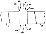
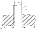
この実施形態では、図3に示すように、溶接ワイヤ22の先端27は、第一の加工部品と第二の加工部品とで画成される開口29の上方に配置される。先端27は、図5にもっと明瞭に示してあるように、開口29の幅31を覆うだけでなく、第一の加工部品20の一部33及び第二の加工部品20の一部33を覆うように延在する。
In this embodiment, as shown in FIG. 3, the
図3に示し、また上記で肉盛用途に関して詳細に述べた通り、溶接ワイヤ22は予熱される。例えば、溶接ワイヤ22は、肉盛用途に関して上記で説明した通り、電源30及び駆動ホイール32を用いて約500℃未満の温度に予熱される。溶接ワイヤ22は、図3に示すように、先端27にレーザビーム18を当てることによって溶融される。図1及び図3に示しまた肉盛用途に関して上記で説明した通り、レーザビーム18を放射するための一つの例示的なレーザ12は、光ファイバケーブルに固定したCW Nd:YAGであって、ケーブルは光ファイバ連結器16に接続される。
As shown in FIG. 3 and described in detail above for the overlay application, the
図3に示すように、先端27をレーザビーム18の下方に配置してレーザビーム18を開口29の長さに沿って前進させる。例えば、図3に示すように、加工部品20,20は並進テーブル34に固定される。並進テーブル34は、加工部品20,20を移動させるための手段を提供し、肉盛用途に関して上記で説明した通り、開口29に沿ってレーザビーム18を前進させる。並進テーブル34に対する別の又は追加の実施形態として、図1に示しまた肉盛用途で上記で説明した通り、ロボットアーム38を使用してレーザビーム18を前進させる。開口29の長さに沿ってレーザビーム18を前進させることによって、第一及び第二の加工部品20,20間の高アスペクト比溶接部37が形成される。本明細書で用いる「高アスペクト比溶接部」という用語は、約2以上のアスペクト比を意味する。さらに具体的な実施形態では、アスペクト比は約3又は4を超える。さらに具体的には、レーザビーム18は開口29に沿って一回前進するだけで高アスペクト比溶接部37を形成する。
As shown in FIG. 3, the
有益なことに、レーザビーム18を先端27に当てて予熱ワイヤ22を溶融すると、公知の方法に比べ、割れ感受性材料20を割れから保護するのに役立つ。さらに具体的には、本発明の方法を用いると、レーザビームを加工部品に当てて溶融池を形成してから溶融池に溶接ワイヤを挿入して溶融させる公知の方法に比べ、加工部品20に移るレーザ出力が低減する。本発明のこの利点は、開口を横断してレーザビームを搖動させて溶融池を形成してから溶融プールに溶接ワイヤを挿入して溶融させる公知の方法と比較した場合にも当てはまる。先端27が開口29の幅31を覆いかつ加工部品20,20の部分33を覆うように延在するので、入射レーザ出力の大部分は溶接ワイヤの溶融のため先端27に当てられる。対照的に、上述の公知の方法では、入射レーザ出力の大部分は加工部品に当てられる。
Beneficially, applying the
本発明の方法は、好適には、割れ感受性材料を含む加工部品20,20の溶接に用いられる。具体的な実施形態では、第一及び第二の材料は共に割れ感受性である。さらに具体的には、第一及び第二の材料は同種又は異種の割れ感受性材料からなる。後者の用途に使用を使用すると特に有利である。2つの異なる割れ感受性材料を接合するのは、2つの異なる材料間の格子不整合のため、同種の割れ感受性材料からなる2つの加工部品を接合するよりも一般に割れを起こし易いからである。しかし、本発明の方法は、入射レーザ出力の大部分が溶接ワイヤ22を溶融するために先端27に当てられるので、割れ感受性基材20を溶接時の割れから保護するのに役立つ。
The method of the present invention is preferably used for
さらに、開口29の長さに沿ってレーザビーム18を1回だけ前進させるて高アスペクト比溶接部37を形成することよって、開口の長さに沿ってレーザビームを数回通過させて溶接部を形成する公知の方法よりも溶接速度が増すという利点がある。加えて、レーザビーム18の1回のパスで溶接部を形成することは、各パスで溶接層を形成するレーザの数回のパスに比べ、きれいな溶接部を形成する。「きれいな溶接部」という用語は、溶接部には溶接部に沿った加工部品の対向壁の変形や曲がりがなく、溶接部がポロシティや割れのような欠陥が少ないことを意味する。一連の層を含む溶接部は、各層の形成で溶接部の深さ方向に対向壁に異なる応力が生じるため、変形を生じ易くなる。
Further, the
加工部品20,20をレーザビーム18の中央部から遮蔽するために、溶接ワイヤ22の直径35は、具体的な実施形態では、開口29の幅31を幅31の約10%だけ超え、さらに具体的には、幅31の約15%だけ超える。例えば、例示的な約0.6mm(すなわち25ミル)の開口幅では、例示的なワイヤ直径は、約0.75mm(すなわち30ミル)である。ガウス分布のレーザビームが先端27で約1mm(すなわち40ミル)の幅を有すると仮定すると、レーザ出力の大部分は溶接ワイヤに移り、溶接ワイヤを効率的に溶融し、かつ加工部品20,20を過熱から保護する。
In order to shield the
具体的な実施形態では、肉盛用途に関して上記で説明した通り、溶接ワイヤ22の先端27は、加工部品20,20に対して約15度〜約30度の角度で配置される。
In a specific embodiment, the
溶接部37を形成するように溶加材を連続的に供給するため、具体的な実施形態に係る方法は、溶接ワイヤ22を連続的に供給して開口29の上方に先端27を維持する段階をさらに含む。例えば、肉盛用途に関して上記で説明しまた図3に示したように、溶接ワイヤ22はワイヤ供給装置24を用いて細長いチューブ26を通して供給される。この実施形態の方法はさらに、肉盛用途に関して上記で説明した通り、コンピュータアルゴリズムを使用してレーザビーム18の前進を制御し、溶接ワイヤの連続供給を制御しかつレーザビーム18の出力及びエネルギーを制御するコントローラ40を含む。有利には、コントローラ40は、加工部品20,20が連続的にレーザ溶接されるようにレーザ12とワイヤ供給装置24と並進テーブル34の動作を同期させる。さらに具体的には、この方法はさらに、溶接ワイヤ22の供給速度、レーザビーム18を前進させる速度及びレーザ出力を選択して、高アスペクト比溶接部37の平均幅41が、開口29の幅31の約1.5倍〜約3倍の範囲内、さらに具体的には約2倍〜約2.5倍の範囲内になるように制御する段階を含む。例示的な高アスペクト比溶接部37を図6に示す。溶接部37の中央部分43は溶接ワイヤ22由来の材料を含み、側部分45は、溶接ワイヤ20由来の材料と加工部品20,20由来の材料とを含む。溶接部37の例示的な寸法は、約5mm(すなわち200ミル)の溶接深さ、約0.6mm(すなわち25ミル)の開口幅31及び約1.2mm(すなわち50ミル)〜約1.7mm(すなわち70ミル)の範囲の平均溶接幅41である。
In order to continuously supply the filler metal so as to form the
ここで図4を参照すると、溶接用途によっては、矢印40で示すように不活性ガスを溶接部の位置に加工部品の両側から導入する。上記のような不活性ガスを用いると溶接部が外来夾雑物から保護される。
Referring now to FIG. 4, depending on the welding application, an inert gas is introduced into the position of the weld from both sides of the workpiece as indicated by
第一の加工部品20を第二の加工部品にレーザ溶接するための装置100の実施形態を、図3、図5及び図6に関して説明する。図5に示すように、装置100は、開口29の幅31を超える直径35の溶接ワイヤ22を備える。装置100はさらに、溶接ワイヤ22を連続的に供給するように構成されたワイヤ供給装置24と、図5に示すように、開口29の幅31を覆いかつ加工部品20,20の部分33を覆うように溶接ワイヤ22の先端27を開口29の上方の位置に導くためのガイド26とを備える。装置100はさらに、溶接ワイヤ22の先端27にレーザビーム18を当てて加工部品20,20間に高アスペクト比溶接部37を形成するように構成されたレーザ12を備える。上述の通り、高アスペクト比溶接部は、約2以上、さらに具体的には約3又は4を超えるアスペクト比を有する。
An embodiment of an apparatus 100 for laser welding a
装置100はさらに、溶接ワイヤ22に電流を供給して溶接ワイヤ22を予熱するように構成された電源30を備える。
The apparatus 100 further includes a
開口29の長さに沿ってレーザビーム18を前進させるため、具体的な実施形態に係る装置100はさらに、例えば光ファイバ連結器16を介してレーザ18に連結され、かつレーザビーム18の照射方向を変更するように構成されたロボットアーム38を備える。ロボットアーム38は図1に示してある。さらに具体的には、装置100はさらに、コンピュータアルゴリズムを使用しかつワイヤ供給装置24、レーザ12及びロボットアーム38を制御するように構成されたコントローラ40を含んでおり、例えばそれらの動作を同期させて加工部品20,20を連続的にレーザ溶接する。
In order to advance the
ロボットア−ムの使用の代替又は追加として、装置100はさらに、先端27がレーザビーム18の下方に位置した状態で開口29の長さに沿ってレーザビーム18を前進させて高アスペクト比溶接部37を形成するように加工部品20,20を移動させるための並進手段34を備える。図3に示すように、例示的な並進手段は並進テーブル34である。さらに具体的には、装置100はさらに、コンピュータアルゴリズムを使用しかつワイヤ供給装置24、レーザ12及び移動手段34を制御するように構成されたコントローラ40を備え、例えばそれらの動作を同期させて加工部品20,20を連続的にレーザ溶接し、さらに具体的には、高アスペクト比溶接部37の平均幅41が開口29の幅31の約1.5倍〜約3倍の範囲内になるように制御する。例示的な高アスペクト比溶接部37を図6に示す。
As an alternative or addition to the use of a robotic arm, the apparatus 100 further advances the
好ましい実施形態を参照して本発明を説明してきたが、本発明の技術的範囲から逸脱することなく本発明の要素に対して種々の変更を加えることができ、均等物で置き換えることができることは当業者には明らかであろう。さらに、本発明の本質的な技術的範囲から逸脱することなく、特定の状況或いは材料を本発明の教示に適合させるように多くの修正を行うことができる。従って、本発明は本発明を実施するために考えられる最良の形態として開示した特定の実施形態に限定されるものではなく、本発明は特許請求の範囲の技術的範囲内に属するあらゆる実施形態を包含する。 Although the invention has been described with reference to preferred embodiments, it is to be understood that various changes can be made to the elements of the invention without departing from the scope of the invention, and equivalents may be substituted. It will be apparent to those skilled in the art. In addition, many modifications may be made to adapt a particular situation or material to the teachings of the invention without departing from the essential scope thereof. Accordingly, the invention is not limited to the specific embodiments disclosed as the best mode contemplated for carrying out the invention, and the invention encompasses any embodiment within the scope of the claims. Include.
10 システム
12 レーザ
14 光ファイバケーブル
16 光ファイバ連結器
18 レーザビーム
20 基材
22 溶接ワイヤ
24 ワイヤ供給装置
26 ガイド
27 溶接ワイヤの先端
28 ガス供給源
29 開口
30 電源
32 駆動ホイール
34 並進テーブル
37 高アスペクト比溶接部
40 コントローラ
DESCRIPTION OF
Claims (22)
第一の加工部品と第二の加工部品とで画成される開口(29)の上方に溶接ワイヤの先端(27)を配置し、先端が、開口の幅(31)及び第一の加工部品の一部と第二の加工部品の一部とを覆うように延在させる段階と、
溶接ワイヤを予熱する段階と、
溶接ワイヤの先端にレーザビーム(18)を当てて溶接ワイヤを溶融する段階と、
溶接ワイヤの先端をレーザビームの下方に配置した状態で開口の長さに沿ってレーザビームを前進させて、第一及び第二の加工部品間に約2以上のアスペクト比を有する高アスペクト比溶接部(37)を形成する段階と、
を含んでなる方法。 A method of laser treating a welding wire (22) to weld a first workpiece (20) comprising a first material to a second workpiece (20) comprising a second material comprising:
The tip (27) of the welding wire is arranged above the opening (29) defined by the first processed part and the second processed part, and the tip is the width (31) of the opening and the first processed part. Extending so as to cover a part of the part and a part of the second processed part;
Preheating the welding wire;
Applying a laser beam (18) to the tip of the welding wire to melt the welding wire;
A high aspect ratio weld having an aspect ratio of about 2 or more between the first and second workpieces by advancing the laser beam along the length of the opening with the tip of the welding wire positioned below the laser beam Forming a portion (37);
Comprising a method.
コンピュータアルゴリズムを使用するコントローラ(40)を用いて、前進と、連続供給と、レーザビーム(18)のエネルギー及び出力とを制御する段階と、
をさらに含む、請求項3記載の方法。 Continuously feeding the welding wire (22) to maintain the tip (27) above the opening (29);
Controlling the advance, continuous delivery, and energy and power of the laser beam (18) with a controller (40) using a computer algorithm;
The method of claim 3, further comprising:
開口の幅を超える直径を有する溶接ワイヤ(22)と、
溶接ワイヤを連続的に供給するように構成されたワイヤ供給装置(24)と、
開口の幅及び第一の加工部品の一部と第二の加工部品の一部とを覆うように溶接ワイヤの先端(27)を開口の上方の位置に導くためのガイド(26)と、
溶接ワイヤの先端にレーザビーム(18)を当てて第一及び第二の加工部品間に約2以上のアスペクト比を有する高アスペクト比溶接部(37)を形成するように構成されたレーザ(12)と、
溶接ワイヤに電流を供給して溶接ワイヤを予熱するように構成された電源(30)と、
を備える装置(100)。 An apparatus (100) for laser welding a first workpiece (20) of a workpiece defining an opening (29) to a second workpiece (20),
A welding wire (22) having a diameter exceeding the width of the opening;
A wire supply device (24) configured to continuously supply a welding wire;
A guide (26) for guiding the tip (27) of the welding wire to a position above the opening so as to cover the width of the opening and a part of the first processed part and a part of the second processed part;
A laser (12) configured to apply a laser beam (18) to the tip of the welding wire to form a high aspect ratio weld (37) having an aspect ratio of about 2 or greater between the first and second workpieces. )When,
A power supply (30) configured to supply current to the welding wire to preheat the welding wire;
A device (100) comprising:
第一の加工部品と第二の加工部品とで画成される開口(29)の上方にその直径(35)が開口の幅を開口の幅の約10%超える溶接ワイヤの先端(27)を配置し、先端が、開口の幅(31)及び第一の加工部品の一部と第二の加工部品の一部とを覆うように延在させる段階と、
溶接ワイヤを予熱する段階と、
溶接ワイヤの先端にレーザビーム(18)を当てて溶接ワイヤを溶融する段階と、
溶接ワイヤの先端をレーザビームの下方に配置した状態で開口の長さに沿ってレーザビームを1回だけ前進させて、第一及び第二の加工部品間に約2以上のアスペクト比を有する高アスペクト比溶接部(37)を形成する段階と、
を含む方法。 A method of laser treating a welding wire (22) to weld a first workpiece (20) comprising a first crack sensitive material to a second workpiece (20) comprising a second crack sensitive material. And
Above the opening (29) defined by the first workpiece and the second workpiece, a welding wire tip (27) whose diameter (35) exceeds the width of the opening by about 10% of the width of the opening. Placing and extending the tip so as to cover the width of the opening (31) and a portion of the first workpiece and a portion of the second workpiece;
Preheating the welding wire;
Applying a laser beam (18) to the tip of the welding wire to melt the welding wire;
A high laser beam having an aspect ratio of about 2 or more between the first and second workpieces by advancing the laser beam only once along the length of the opening with the tip of the welding wire positioned below the laser beam. Forming an aspect ratio weld (37);
Including methods.
コンピュータアルゴリズムを使用するコントローラ(40)を用いて、前進と、連続供給と、レーザビーム(18)のエネルギー及び出力とを制御する段階と、
連続供給のための供給速度を選択し、前進速度を選択しかつレーザ出力を選択して、高アスペクト比溶接部(37)の平均幅(41)が、開口(29)の幅(31)の約1.5倍〜約3倍の範囲内になるように制御する段階と、
をさらに含む、請求項21記載の方法。 Continuously feeding the welding wire (22) to maintain the tip (27) above the opening (29);
Controlling the advance, continuous delivery, and energy and power of the laser beam (18) with a controller (40) using a computer algorithm;
Select the feed rate for continuous feed, choose the advance rate and choose the laser power, the average width (41) of the high aspect ratio weld (37) is the width (31) of the opening (29) Controlling to be within a range of about 1.5 times to about 3 times;
The method of claim 21, further comprising:
Applications Claiming Priority (2)
| Application Number | Priority Date | Filing Date | Title |
|---|---|---|---|
| US09/683,594 US6521861B2 (en) | 2000-02-07 | 2002-01-23 | Method and apparatus for increasing welding rate for high aspect ratio welds |
| PCT/US2003/002040 WO2003062605A1 (en) | 2002-01-23 | 2003-01-23 | Method and apparatus for increasing welding rates for high aspect ratio welds |
Publications (2)
| Publication Number | Publication Date |
|---|---|
| JP2005515895A true JP2005515895A (en) | 2005-06-02 |
| JP2005515895A5 JP2005515895A5 (en) | 2006-03-09 |
Family
ID=27613749
Family Applications (1)
| Application Number | Title | Priority Date | Filing Date |
|---|---|---|---|
| JP2003562457A Pending JP2005515895A (en) | 2002-01-23 | 2003-01-23 | Method and apparatus for increasing welding speed for high aspect ratio welds |
Country Status (5)
| Country | Link |
|---|---|
| US (1) | US6521861B2 (en) |
| EP (1) | EP1478827A1 (en) |
| JP (1) | JP2005515895A (en) |
| KR (1) | KR20040073591A (en) |
| WO (1) | WO2003062605A1 (en) |
Cited By (2)
| Publication number | Priority date | Publication date | Assignee | Title |
|---|---|---|---|---|
| JP2010172941A (en) * | 2009-01-30 | 2010-08-12 | Hitachi Ltd | Laser beam welding apparatus |
| JP2011041982A (en) * | 2009-08-20 | 2011-03-03 | General Electric Co <Ge> | System and method of dual laser beam welding of first and second filler metal |
Families Citing this family (48)
| Publication number | Priority date | Publication date | Assignee | Title |
|---|---|---|---|---|
| DE10006852C5 (en) * | 2000-02-16 | 2004-08-26 | Anders, Michael, Dr.-Ing. | Method and device for joining workpiece parts by means of an energy beam, in particular a laser beam |
| DE10328596A1 (en) * | 2003-06-25 | 2005-01-13 | Mtu Aero Engines Gmbh | Welding of super alloy materials for such as gas turbines has laser applied together with weld wire in an inductive heater |
| FR2866990B1 (en) * | 2004-02-27 | 2006-07-28 | Tyco Electronics France Sas | INTEGRATED FUSE CONNECTION GRID, METHOD FOR MANUFACTURING SAME, AND SYSTEM FOR IMPLEMENTING SAID METHOD |
| US20050194367A1 (en) * | 2004-03-02 | 2005-09-08 | Fredrick William G.Jr. | System and method for remote controlled actuation of laser processing head |
| US7211763B2 (en) * | 2004-12-22 | 2007-05-01 | General Electric Company | Photon energy material processing using liquid core waveguide and a computer program for controlling the same |
| DE102005061452A1 (en) * | 2005-12-22 | 2007-07-05 | Volkswagen Ag | Joining by means of energy beam and additional material |
| DE102006021755A1 (en) * | 2006-05-10 | 2007-11-15 | Edag Engineering + Design Ag | Energy beam soldering or welding of components |
| EP1880791A1 (en) * | 2006-07-21 | 2008-01-23 | Aleris Aluminum Koblenz GmbH | Process and apparatus for laser joining two components through the use of a laminar inert gas flow coaxial to a metal filler wire |
| US7851984B2 (en) * | 2006-08-08 | 2010-12-14 | Federal-Mogul World Wide, Inc. | Ignition device having a reflowed firing tip and method of construction |
| KR100833640B1 (en) * | 2007-03-05 | 2008-05-30 | 한국과학기술원 | Device and method for joining micro wire and micro structure using laser |
| US8071907B2 (en) * | 2007-05-12 | 2011-12-06 | Honeywell International Inc. | Button attachment method for saw torque sensor |
| US8699667B2 (en) * | 2007-10-02 | 2014-04-15 | General Electric Company | Apparatus for x-ray generation and method of making same |
| US20090188894A1 (en) * | 2008-01-28 | 2009-07-30 | Honeywell International Inc. | Welding guide nozzle including nozzle tip for precision weld wire positioning |
| US8653417B2 (en) * | 2009-01-13 | 2014-02-18 | Lincoln Global, Inc. | Method and system to start and use a combination filler wire feed and high intensity energy source |
| US9085041B2 (en) | 2009-01-13 | 2015-07-21 | Lincoln Global, Inc. | Method and system to start and use combination filler wire feed and high intensity energy source for welding |
| US20130092667A1 (en) * | 2009-01-13 | 2013-04-18 | Lincoln Global, Inc. | Method and System to Start and Use Combination Filler Wire Feed and High Intensity Energy Source for Welding |
| US10086461B2 (en) | 2009-01-13 | 2018-10-02 | Lincoln Global, Inc. | Method and system to start and use combination filler wire feed and high intensity energy source for welding |
| WO2011055373A1 (en) * | 2009-11-03 | 2011-05-12 | The Secretary, Department Of Atomic Energy,Govt.Of India. | Niobium based superconducting radio frequency (scrf) cavities comprising niobium components joined by laser welding; method and apparatus for manufacturing such cavities |
| US8895886B2 (en) * | 2011-03-15 | 2014-11-25 | General Electric Company | Cladding application method and apparatus using hybrid laser process |
| EP2591872A1 (en) * | 2011-11-11 | 2013-05-15 | Siemens Aktiengesellschaft | Remelting method and subsequent filling and resulting component |
| US10105780B2 (en) | 2012-07-06 | 2018-10-23 | Lincoln Global, Inc. | Method and system of using a consumable and a heat source with a weld puddle |
| US9687929B2 (en) * | 2012-07-06 | 2017-06-27 | Lincoln Global, Inc. | Method and system of using consumable with weld puddle |
| US20140008328A1 (en) * | 2012-07-06 | 2014-01-09 | Lincoln Global, Inc. | System and method for forming a joint with a hot wire |
| US20140034621A1 (en) * | 2012-08-03 | 2014-02-06 | Lincoln Global, Inc. | Method and system of hot wire joint design for out-of-position welding |
| US20140042138A1 (en) * | 2012-08-10 | 2014-02-13 | Lincoln Global, Inc. | Hot-wire welding power supply |
| WO2014024036A1 (en) * | 2012-08-10 | 2014-02-13 | Lincoln Global, Inc. | Hot-wire welding power supply |
| CN104822484A (en) * | 2012-12-06 | 2015-08-05 | 林肯环球股份有限公司 | Method and system to start and use combination filler wire feed and high intensity energy source for welding |
| WO2014094882A1 (en) * | 2012-12-21 | 2014-06-26 | European Space Agency | Additive manufacturing method using focused light heating source |
| US20140263193A1 (en) * | 2013-03-15 | 2014-09-18 | Lincoln Global, Inc. | Consumable and method and system to utilize consumable in a hot-wire system |
| US9067278B2 (en) | 2013-03-29 | 2015-06-30 | Photon Automation, Inc. | Pulse spread laser |
| US9498838B2 (en) | 2013-07-24 | 2016-11-22 | Lincoln Global, Inc. | System and method of controlling heat input in tandem hot-wire applications |
| EP3095548A4 (en) * | 2014-01-17 | 2017-09-27 | Hitachi, Ltd. | Laser welding method and welded joint |
| US9808886B2 (en) * | 2014-01-24 | 2017-11-07 | Lincoln Global, Inc. | Method and system for additive manufacturing using high energy source and hot-wire |
| US10464168B2 (en) | 2014-01-24 | 2019-11-05 | Lincoln Global, Inc. | Method and system for additive manufacturing using high energy source and hot-wire |
| JP2015202594A (en) * | 2014-04-11 | 2015-11-16 | セイコーエプソン株式会社 | Molding device and molding method |
| FR3027393B1 (en) * | 2014-10-17 | 2016-10-07 | Renault Sa | METHOD AND DEVICE FOR DIAGNOSING THE QUALITY OF A LASER WELD CORD |
| DE102015008919A1 (en) * | 2015-07-15 | 2017-01-19 | Evobeam GmbH | Process for the additive production of metallic components |
| GB201515386D0 (en) * | 2015-08-28 | 2015-10-14 | Materials Solutions Ltd | Additive manufacturing |
| US10058956B2 (en) * | 2015-11-17 | 2018-08-28 | Illinois Tool Works Inc. | Metalworking wire feeder system with force control operation |
| US10173288B2 (en) * | 2015-11-17 | 2019-01-08 | Illinois Tool Works Inc. | Metalworking system with force controlled wire feed start operation |
| PL3265263T3 (en) * | 2016-02-23 | 2019-06-28 | Fronius International Gmbh | Welding device with a laser preheating device for filler wire |
| US11027362B2 (en) | 2017-12-19 | 2021-06-08 | Lincoln Global, Inc. | Systems and methods providing location feedback for additive manufacturing |
| CN109514068B (en) * | 2018-10-31 | 2022-01-14 | 南京理工大学 | Device based on electron beam hot filament fuse vibration material disk |
| FR3092509B1 (en) | 2019-02-13 | 2022-03-04 | Safran Aircraft Engines | THREE-DIMENSIONAL PRINTING DEVICE |
| JP7325194B2 (en) * | 2019-02-19 | 2023-08-14 | 三菱重工業株式会社 | Welded product manufacturing method, welded product manufacturing system, and welded product |
| CN111299837A (en) * | 2019-11-27 | 2020-06-19 | 北京工业大学 | Efficient laser additive manufacturing method based on wire thermal conduction welding |
| CN111331310B (en) * | 2019-12-05 | 2021-11-30 | 中国船舶重工集团公司第七二五研究所 | Defect repairing method for thin-wall barrel titanium alloy casting with large opening on barrel wall |
| EP3892414A1 (en) * | 2020-04-06 | 2021-10-13 | Bystronic Laser AG | Laser processing machine |
Citations (4)
| Publication number | Priority date | Publication date | Assignee | Title |
|---|---|---|---|---|
| JPH04157078A (en) * | 1990-10-16 | 1992-05-29 | Mitsubishi Heavy Ind Ltd | Laser beam welding method |
| JPH04157079A (en) * | 1990-10-16 | 1992-05-29 | Mitsubishi Heavy Ind Ltd | Laser beam welding method |
| JP2000005888A (en) * | 1998-06-24 | 2000-01-11 | Toyota Motor Corp | Laser butt welding |
| WO2000015382A1 (en) * | 1998-09-15 | 2000-03-23 | Chromalloy Gas Turbine Corporation | Laser welding superalloy articles |
Family Cites Families (16)
| Publication number | Priority date | Publication date | Assignee | Title |
|---|---|---|---|---|
| US3555239A (en) * | 1966-11-16 | 1971-01-12 | William J Kerth | Welding machine with digital pulse control |
| JPS58119481A (en) * | 1982-01-08 | 1983-07-15 | Kawasaki Steel Corp | Laser beam melting welding method |
| DE129962T1 (en) | 1983-04-20 | 1985-06-20 | British Shipbuilders, Newcastle-Upon-Tyne | LASER BEAM WELDING. |
| JPS61232080A (en) * | 1985-04-09 | 1986-10-16 | Nippon Kokan Kk <Nkk> | Laser welding method |
| US4580026A (en) * | 1985-06-05 | 1986-04-01 | Westinghouse Electric Corp. | Method and apparatus for controlling the temperature of continuously fed wires |
| US4737612A (en) | 1987-02-04 | 1988-04-12 | Westinghouse Electric Corp. | Method of welding |
| US4803334A (en) * | 1987-11-16 | 1989-02-07 | Westinghouse Electric Corp. | Method for laser beam welding metal matrix composite components |
| DE3905684A1 (en) | 1989-02-24 | 1990-08-30 | Ulrich Prof Dr Ing Draugelates | Build-up welding process |
| DE3928092A1 (en) | 1989-08-25 | 1991-02-28 | Mordike Barry Leslie | Coating metal surfaces using laser-wire coating method - with wire electro-resistance preheated to improve flow capabilities and improve coating qualities |
| JP2945294B2 (en) * | 1995-02-15 | 1999-09-06 | 川崎製鉄株式会社 | Laser welding method for high carbon steel strip |
| US5914059A (en) | 1995-05-01 | 1999-06-22 | United Technologies Corporation | Method of repairing metallic articles by energy beam deposition with reduced power density |
| US5889254A (en) | 1995-11-22 | 1999-03-30 | General Electric Company | Method and apparatus for Nd: YAG hardsurfacing |
| US5793009A (en) * | 1996-06-20 | 1998-08-11 | General Electric Company | Apparatus for joining metal components using broad, thin filler nozzle |
| US5958261A (en) * | 1997-07-17 | 1999-09-28 | General Electric Company | Apparatus for welding with preheated filler material |
| JP2001090502A (en) * | 1999-09-24 | 2001-04-03 | Toshiba Corp | Manufacture of gas turbine blade |
| KR20010078305A (en) * | 2000-02-07 | 2001-08-20 | 제이 엘. 차스킨, 버나드 스나이더, 아더엠. 킹 | Method and apparatus for increasing cladding or welding rates |
-
2002
- 2002-01-23 US US09/683,594 patent/US6521861B2/en not_active Expired - Fee Related
-
2003
- 2003-01-23 JP JP2003562457A patent/JP2005515895A/en active Pending
- 2003-01-23 EP EP03732071A patent/EP1478827A1/en not_active Withdrawn
- 2003-01-23 KR KR10-2004-7011479A patent/KR20040073591A/en active IP Right Grant
- 2003-01-23 WO PCT/US2003/002040 patent/WO2003062605A1/en active Application Filing
Patent Citations (4)
| Publication number | Priority date | Publication date | Assignee | Title |
|---|---|---|---|---|
| JPH04157078A (en) * | 1990-10-16 | 1992-05-29 | Mitsubishi Heavy Ind Ltd | Laser beam welding method |
| JPH04157079A (en) * | 1990-10-16 | 1992-05-29 | Mitsubishi Heavy Ind Ltd | Laser beam welding method |
| JP2000005888A (en) * | 1998-06-24 | 2000-01-11 | Toyota Motor Corp | Laser butt welding |
| WO2000015382A1 (en) * | 1998-09-15 | 2000-03-23 | Chromalloy Gas Turbine Corporation | Laser welding superalloy articles |
Cited By (2)
| Publication number | Priority date | Publication date | Assignee | Title |
|---|---|---|---|---|
| JP2010172941A (en) * | 2009-01-30 | 2010-08-12 | Hitachi Ltd | Laser beam welding apparatus |
| JP2011041982A (en) * | 2009-08-20 | 2011-03-03 | General Electric Co <Ge> | System and method of dual laser beam welding of first and second filler metal |
Also Published As
| Publication number | Publication date |
|---|---|
| EP1478827A1 (en) | 2004-11-24 |
| WO2003062605A1 (en) | 2003-07-31 |
| US20020117485A1 (en) | 2002-08-29 |
| US6521861B2 (en) | 2003-02-18 |
| KR20040073591A (en) | 2004-08-19 |
Similar Documents
| Publication | Publication Date | Title |
|---|---|---|
| US6521861B2 (en) | Method and apparatus for increasing welding rate for high aspect ratio welds | |
| JP7392022B2 (en) | Visible laser welding of electronic packaging, automotive electrical equipment, batteries, and other components | |
| EP2744619B1 (en) | Method to start and use combination filler wire feed and high intensity energy source for welding | |
| US10888944B2 (en) | Method and system of using consumable with weld puddle | |
| US9718147B2 (en) | Method and system to start and use combination filler wire feed and high intensity energy source for root pass welding of the inner diameter of clad pipe | |
| US9782850B2 (en) | Method and system to start and use combination filler wire feed and high intensity energy source for welding | |
| JP6404360B2 (en) | System and method for welding using AC welding waveform and enhanced consumable material for improving welding of galvanized workpieces | |
| JP3762676B2 (en) | Work welding method | |
| KR102093528B1 (en) | Method of and system for starting and using in combination a filler wire feed and arc generating source for welding | |
| US20130092667A1 (en) | Method and System to Start and Use Combination Filler Wire Feed and High Intensity Energy Source for Welding | |
| US20130327749A1 (en) | Method and system to start and use combination filler wire feed and high intensity energy source for welding aluminum to steel | |
| JP2009500177A (en) | System and method for laser resistance hybrid welding | |
| JP2008114290A (en) | High temperature electron beam welding | |
| US20060261045A1 (en) | Multi-heat source laser brazing system and method | |
| WO2014087227A1 (en) | Method and system to start and use combination filler wire feed and high intensity energy source for welding | |
| JP5812527B2 (en) | Hot wire laser welding method and apparatus | |
| KR100530718B1 (en) | Apparatus for Eliminating of Coating Material on Coated Metal Plate and Welding Method Using That | |
| EP1127651A1 (en) | Method and apparatus for increasing cladding or welding rates | |
| JP3767359B2 (en) | Butt welding method and welded thin steel plate | |
| JP4113359B2 (en) | Method for treating recesses formed in aluminum welds | |
| WO2015022569A2 (en) | Method and system to start and use combination filler wire feed and high intensity energy source for welding aluminium to steel | |
| JP2023173547A (en) | Laser arc hybrid welding apparatus |
Legal Events
| Date | Code | Title | Description |
|---|---|---|---|
| A521 | Request for written amendment filed |
Free format text: JAPANESE INTERMEDIATE CODE: A523 Effective date: 20060119 |
|
| A621 | Written request for application examination |
Free format text: JAPANESE INTERMEDIATE CODE: A621 Effective date: 20060119 |
|
| A131 | Notification of reasons for refusal |
Free format text: JAPANESE INTERMEDIATE CODE: A131 Effective date: 20080715 |
|
| A601 | Written request for extension of time |
Free format text: JAPANESE INTERMEDIATE CODE: A601 Effective date: 20081015 |
|
| A602 | Written permission of extension of time |
Free format text: JAPANESE INTERMEDIATE CODE: A602 Effective date: 20081022 |
|
| A131 | Notification of reasons for refusal |
Free format text: JAPANESE INTERMEDIATE CODE: A131 Effective date: 20090331 |
|
| A601 | Written request for extension of time |
Free format text: JAPANESE INTERMEDIATE CODE: A601 Effective date: 20090630 |
|
| RD02 | Notification of acceptance of power of attorney |
Free format text: JAPANESE INTERMEDIATE CODE: A7422 Effective date: 20090630 |
|
| RD04 | Notification of resignation of power of attorney |
Free format text: JAPANESE INTERMEDIATE CODE: A7424 Effective date: 20090630 |
|
| A602 | Written permission of extension of time |
Free format text: JAPANESE INTERMEDIATE CODE: A602 Effective date: 20090707 |
|
| A601 | Written request for extension of time |
Free format text: JAPANESE INTERMEDIATE CODE: A601 Effective date: 20090730 |
|
| A602 | Written permission of extension of time |
Free format text: JAPANESE INTERMEDIATE CODE: A602 Effective date: 20090806 |
|
| A601 | Written request for extension of time |
Free format text: JAPANESE INTERMEDIATE CODE: A601 Effective date: 20090828 |
|
| A602 | Written permission of extension of time |
Free format text: JAPANESE INTERMEDIATE CODE: A602 Effective date: 20090904 |
|
| A521 | Request for written amendment filed |
Free format text: JAPANESE INTERMEDIATE CODE: A523 Effective date: 20090929 |
|
| A131 | Notification of reasons for refusal |
Free format text: JAPANESE INTERMEDIATE CODE: A131 Effective date: 20091222 |
|
| A601 | Written request for extension of time |
Free format text: JAPANESE INTERMEDIATE CODE: A601 Effective date: 20100319 |
|
| A602 | Written permission of extension of time |
Free format text: JAPANESE INTERMEDIATE CODE: A602 Effective date: 20100329 |
|
| A601 | Written request for extension of time |
Free format text: JAPANESE INTERMEDIATE CODE: A601 Effective date: 20100422 |
|
| A602 | Written permission of extension of time |
Free format text: JAPANESE INTERMEDIATE CODE: A602 Effective date: 20100430 |
|
| A601 | Written request for extension of time |
Free format text: JAPANESE INTERMEDIATE CODE: A601 Effective date: 20100521 |
|
| A602 | Written permission of extension of time |
Free format text: JAPANESE INTERMEDIATE CODE: A602 Effective date: 20100528 |
|
| A02 | Decision of refusal |
Free format text: JAPANESE INTERMEDIATE CODE: A02 Effective date: 20101116 |