JP2009145351A - Electrical leadthrough module and method for production thereof - Google Patents
Electrical leadthrough module and method for production thereof Download PDFInfo
- Publication number
- JP2009145351A JP2009145351A JP2008320700A JP2008320700A JP2009145351A JP 2009145351 A JP2009145351 A JP 2009145351A JP 2008320700 A JP2008320700 A JP 2008320700A JP 2008320700 A JP2008320700 A JP 2008320700A JP 2009145351 A JP2009145351 A JP 2009145351A
- Authority
- JP
- Japan
- Prior art keywords
- electrical
- lead
- electrical lead
- conductors
- conductor
- Prior art date
- Legal status (The legal status is an assumption and is not a legal conclusion. Google has not performed a legal analysis and makes no representation as to the accuracy of the status listed.)
- Granted
Links
- 238000004519 manufacturing process Methods 0.000 title claims description 9
- 239000004020 conductor Substances 0.000 claims abstract description 126
- 239000011521 glass Substances 0.000 claims description 23
- 238000009413 insulation Methods 0.000 claims description 11
- 238000000034 method Methods 0.000 claims description 11
- 241000446313 Lamella Species 0.000 claims description 6
- 230000000149 penetrating effect Effects 0.000 claims description 4
- 238000006073 displacement reaction Methods 0.000 claims description 2
- 239000011810 insulating material Substances 0.000 description 4
- 239000002184 metal Substances 0.000 description 3
- 230000005540 biological transmission Effects 0.000 description 1
- 230000015556 catabolic process Effects 0.000 description 1
- 238000002788 crimping Methods 0.000 description 1
- 238000006731 degradation reaction Methods 0.000 description 1
- 230000001419 dependent effect Effects 0.000 description 1
- 238000010586 diagram Methods 0.000 description 1
- 230000000694 effects Effects 0.000 description 1
- 230000002349 favourable effect Effects 0.000 description 1
- 238000010438 heat treatment Methods 0.000 description 1
- 238000005304 joining Methods 0.000 description 1
- 230000007774 longterm Effects 0.000 description 1
- 238000005259 measurement Methods 0.000 description 1
- 230000003647 oxidation Effects 0.000 description 1
- 238000007254 oxidation reaction Methods 0.000 description 1
- 238000007789 sealing Methods 0.000 description 1
- 239000007787 solid Substances 0.000 description 1
- 239000012265 solid product Substances 0.000 description 1
- 238000003466 welding Methods 0.000 description 1
Images


Classifications
-
- H—ELECTRICITY
- H02—GENERATION; CONVERSION OR DISTRIBUTION OF ELECTRIC POWER
- H02G—INSTALLATION OF ELECTRIC CABLES OR LINES, OR OF COMBINED OPTICAL AND ELECTRIC CABLES OR LINES
- H02G3/00—Installations of electric cables or lines or protective tubing therefor in or on buildings, equivalent structures or vehicles
- H02G3/22—Installations of cables or lines through walls, floors or ceilings, e.g. into buildings
-
- H—ELECTRICITY
- H01—ELECTRIC ELEMENTS
- H01R—ELECTRICALLY-CONDUCTIVE CONNECTIONS; STRUCTURAL ASSOCIATIONS OF A PLURALITY OF MUTUALLY-INSULATED ELECTRICAL CONNECTING ELEMENTS; COUPLING DEVICES; CURRENT COLLECTORS
- H01R13/00—Details of coupling devices of the kinds covered by groups H01R12/70 or H01R24/00 - H01R33/00
- H01R13/46—Bases; Cases
- H01R13/53—Bases or cases for heavy duty; Bases or cases for high voltage with means for preventing corona or arcing
-
- H—ELECTRICITY
- H01—ELECTRIC ELEMENTS
- H01R—ELECTRICALLY-CONDUCTIVE CONNECTIONS; STRUCTURAL ASSOCIATIONS OF A PLURALITY OF MUTUALLY-INSULATED ELECTRICAL CONNECTING ELEMENTS; COUPLING DEVICES; CURRENT COLLECTORS
- H01R13/00—Details of coupling devices of the kinds covered by groups H01R12/70 or H01R24/00 - H01R33/00
- H01R13/02—Contact members
- H01R13/15—Pins, blades or sockets having separate spring member for producing or increasing contact pressure
- H01R13/187—Pins, blades or sockets having separate spring member for producing or increasing contact pressure with spring member in the socket
-
- Y—GENERAL TAGGING OF NEW TECHNOLOGICAL DEVELOPMENTS; GENERAL TAGGING OF CROSS-SECTIONAL TECHNOLOGIES SPANNING OVER SEVERAL SECTIONS OF THE IPC; TECHNICAL SUBJECTS COVERED BY FORMER USPC CROSS-REFERENCE ART COLLECTIONS [XRACs] AND DIGESTS
- Y10—TECHNICAL SUBJECTS COVERED BY FORMER USPC
- Y10S—TECHNICAL SUBJECTS COVERED BY FORMER USPC CROSS-REFERENCE ART COLLECTIONS [XRACs] AND DIGESTS
- Y10S439/00—Electrical connectors
- Y10S439/933—Special insulation
- Y10S439/935—Glass or ceramic contact pin holder
-
- Y—GENERAL TAGGING OF NEW TECHNOLOGICAL DEVELOPMENTS; GENERAL TAGGING OF CROSS-SECTIONAL TECHNOLOGIES SPANNING OVER SEVERAL SECTIONS OF THE IPC; TECHNICAL SUBJECTS COVERED BY FORMER USPC CROSS-REFERENCE ART COLLECTIONS [XRACs] AND DIGESTS
- Y10—TECHNICAL SUBJECTS COVERED BY FORMER USPC
- Y10T—TECHNICAL SUBJECTS COVERED BY FORMER US CLASSIFICATION
- Y10T29/00—Metal working
- Y10T29/53—Means to assemble or disassemble
- Y10T29/5313—Means to assemble electrical device
- Y10T29/532—Conductor
- Y10T29/53209—Terminal or connector
Abstract
Description
本発明は、包括的には電気リードスルーに関し、特に、圧力容器又は安全容器、エンジンリード線、ハウジングリード線、及び容器リード線用の電気リードスルーに関する。 The present invention relates generally to electrical leadthroughs, and more particularly to electrical leadthroughs for pressure vessels or safety containers, engine leads, housing leads, and container leads.
安全容器、例えば原子炉格納容器又は他の圧力容器、並びに給電用及び制御信号及び測定信号の通過用の他の電力引込線の動作安全性の最大要件を満たすために、多くの場合は電気リードスルー及びリードスルーモジュールがこの分野で用いられ、安全要件が高い場合、2つ以上の互いに離間した電気リードスルーが1つ又は複数の導体を絶縁要素に通して互いに縦列にケーブル接続されている。リードスルーは、一般的に金属製ではあるがプラスチック製でもある支持要素内に保持される。概して、離間して互いにケーブル接続されるこのようなリードスルーが2つ用いられる。 In order to meet the maximum operational safety requirements of safety vessels, such as reactor containments or other pressure vessels, and other power service lines for feeding and for passing control and measurement signals, electrical lead-through is often used When lead-through modules are used in this field and safety requirements are high, two or more spaced electrical lead-throughs are cabled in tandem with each other through one or more conductors through an insulating element. The lead-through is held in a support element that is typically made of metal but also of plastic. In general, two such leadthroughs are used that are spaced apart and cabled together.
これまで、このようなリードスルーモジュールの電気リードスルーの導体は、ケーブルによって互いに電気的に接続されていた。導体をリードスルーに接合するために、圧着接続及びねじ接続が用いられていた。しかしながら、この接続様式にはいくつかの欠点がある。この接続は、「バグ」が多く、大きな空間を取り、特に壊さなければ切断することができない。圧着筐体及びケーブルを互いに慎重に調整しなければならない。さらに、導体のこのタイプの電気的接触は、非常に高価で労働集約的である。これは、極めて一般的である1つのこのようなリードスルーモジュールにおいて、導体それぞれを互いに接続する接続部が100個をはるかに超える場合に特に重要である。 Until now, the electrical lead-through conductors of such lead-through modules have been electrically connected to each other by cables. Crimp connections and screw connections have been used to join conductors to leadthroughs. However, this connection mode has several drawbacks. This connection has many "bugs", takes up a lot of space and cannot be broken unless broken. The crimp housing and cable must be carefully adjusted to each other. Furthermore, this type of electrical contact of conductors is very expensive and labor intensive. This is particularly important in one such lead-through module, which is very common, when there are far more than 100 connections connecting each conductor to each other.
したがって、本発明は、リードスルーの導体を互いにしっかりと接続することができ接続の実施が容易であるリードスルーモジュールの提供に関する問題に基づく。 The present invention is therefore based on the problem of providing a lead-through module in which the lead-through conductors can be firmly connected to one another and the connection is easy to implement.
今回、この問題は、独立請求項の主題によって非常に驚くほど単純な方法で解決される。好適な実施の形態及び改良形態は、従属請求項に明記されている。したがって、本発明は、絶縁要素を貫通して絶縁要素の両側に突出する少なくとも1つの導体をそれぞれが有する少なくとも2つの離間した電気リードスルーを備える、電気リードスルーモジュールであって、電気リードスルーの導体は、リードスルーの少なくとも一方の導体(複数可)に対して軸方向に変位可能な接続要素によって互いに電気的に接続される、電気リードスルーモジュールを提供する。 This problem is now solved in a very surprisingly simple manner by the subject matter of the independent claims. Preferred embodiments and refinements are specified in the dependent claims. Accordingly, the present invention is an electrical leadthrough module comprising at least two spaced apart electrical leadthroughs each having at least one conductor penetrating the insulating element and projecting on opposite sides of the insulating element. The conductors provide an electrical lead-through module that is electrically connected to each other by a connecting element that is axially displaceable with respect to at least one conductor (s) of the lead-through.
したがって、このようなリードスルーモジュールを製造する方法は、絶縁要素を貫通して絶縁要素の両側に突出する少なくとも1つの導体をそれぞれが有する少なくとも2つの電気リードスルーが、導体に対して軸方向に変位可能であるように配置されている接続要素によって互いに電気的に接続されることに基づく。 Therefore, a method for manufacturing such a lead-through module is such that at least two electrical lead-throughs, each having at least one conductor penetrating the insulating element and projecting on both sides of the insulating element, are axial with respect to the conductor. Based on being electrically connected to each other by connecting elements arranged to be displaceable.
具体的には、電気リードスルーモジュールは、以下のように設計されることが好ましい。少なくとも2つの電気リードスルーが設けられ、リードスルーのそれぞれが、ガラス絶縁要素が気密にシールするように融着される少なくとも1つの軸方向開口を有するフランジを備え、ガラス絶縁要素を貫通してガラス絶縁要素の両側に延在して絶縁要素にシールされる複数の導体が設けられ、電気リードスルーの導体は、軸方向に見て対になって長手方向軸が整列し、軸方向に離間し、リードスルーの少なくとも一方の導体に対して軸方向に変位可能に配置されている導電要素によって互いに電気的に接続され、各ソケットコンタクトで電気的接触が行われ、絶縁要素間で接続要素を囲む空間が密閉される。 Specifically, the electrical lead-through module is preferably designed as follows. At least two electrical leadthroughs are provided, each of the leadthroughs comprising a flange having at least one axial opening that is fused so that the glass insulation element is hermetically sealed, and the glass penetrates the glass insulation element. A plurality of conductors extending on both sides of the insulating element and sealed to the insulating element are provided, and the electrical lead-through conductors are paired when viewed in the axial direction, with the longitudinal axes aligned and spaced apart in the axial direction. , Electrically connected to each other by means of conductive elements arranged axially displaceable with respect to at least one conductor of the lead-through, making electrical contact at each socket contact and surrounding the connecting element between the insulating elements The space is sealed.
このようなリードスルーの対応する製造法は、少なくとも2つの電気リードスルーを製造することに基づき、このとき、リードスルーのそれぞれが、ガラス絶縁要素が気密にシールするように融着される少なくとも1つの軸方向開口を有するフランジを備え、ガラス絶縁要素を貫通してガラス絶縁要素の両側に延在する複数の導体が、ガラス絶縁要素にシールされ、リードスルーの配置は、電気リードスルーの導体が軸方向に見て対になって長手方向軸が整列して、リードスルーの少なくとも一方の導体に対して軸方向に変位可能に配置されている導電接続要素によってそれぞれが1つのソケットコンタクトで互いに電気的に接続されるようになっており、組み立て時に2つのリードスルーが軸方向に押し合わされることで導電接続要素がこれと接触する導体に沿って軸方向に変位することにより、絶縁要素間で接続要素を囲む空間が密閉されるようにリードスルーが軸方向に離間して固定されるようになっている。軸方向に変位可能なコンタクトにより、この場合、導体の接触に必要な費用は特にない。むしろ、導体が軸方向に整列することで電気的接触がレセプタクルによって確立されるように、リードスルーが組み合わせられる。したがって、接触はリードスルーの接合と同時に行われる。 A corresponding manufacturing method for such a lead-through is based on manufacturing at least two electrical lead-throughs, each of which is fused at least so that the glass insulating element is hermetically sealed. A plurality of conductors having a flange with two axial openings and extending through the glass insulation element and extending on both sides of the glass insulation element are sealed to the glass insulation element. Electrically connected to each other in one socket contact by means of conductive connecting elements which are arranged in pairs in the axial direction and whose longitudinal axes are aligned and arranged axially displaceable with respect to at least one conductor of the lead-through. Are connected, and the two lead-throughs are pushed together in the axial direction during assembly, so that the conductive connecting element can be connected. By displacing axially along the conductors in contact with, the lead-through so that the space surrounding the connection elements between the insulating element is sealed is adapted to be secured at a distance from each other in the axial direction. Due to the axially displaceable contacts, in this case there is no particular expense required for contact of the conductors. Rather, the lead-through is combined so that electrical contact is established by the receptacle by the axial alignment of the conductors. Therefore, contact is made at the same time as lead-through bonding.
概して、導体ごとに1つのガラス絶縁要素を用いることができるか、又は共通の絶縁要素内に複数の導体をシールすることさえできる。 In general, one glass insulating element per conductor can be used, or even multiple conductors can be sealed within a common insulating element.
接続要素は、特に軸方向に変位可能な、好ましくは剛性の棒から成り得る。 The connecting element can consist of a preferably rigid rod, which can be displaced in particular in the axial direction.
電気的接触を確立するために、本発明の特に好適な一実施の形態の接続要素は、例えば上述の棒の構成要素としてのソケット又はソケットコンタクトを含む。 In order to establish an electrical contact, the connection element of a particularly preferred embodiment of the invention comprises a socket or socket contact, for example as a component of the rod described above.
導体に対して軸方向に変位可能であるように配置されている棒の導体は、互いに離間して電気的に接続されるため、既知のケーブルと比較して一様に安定した装置が得られる。また、導体と棒との接続は、はるかに容易に必要な空間を大きく取らずに行うことができる。これは特に、複数の導電体を有するような電気リードスルーに当てはまる。接続要素として棒が用いられる場合、リードスルーの導体(複数可)の片側又は両側に、軸方向に変位可能な棒が保持されるレセプタクルを設けることができる。特に、両方のリードスルーの導体のそれぞれが、軸方向に変位可能な接続要素として棒が取り付けられるレセプタクルを有することができる。 The conductors of the rods arranged so as to be axially displaceable with respect to the conductor are electrically connected apart from each other, resulting in a uniformly stable device compared to known cables . In addition, the connection between the conductor and the rod can be made much more easily without taking a large space. This is especially true for electrical leadthroughs having multiple conductors. When a rod is used as the connecting element, a receptacle for holding the axially displaceable rod can be provided on one or both sides of the lead-through conductor (s). In particular, each of the conductors of both lead-throughs can have a receptacle to which a rod is attached as an axially displaceable connecting element.
本発明の別の設計の実施の形態によれば、リードスルーモジュールの長さに応じて棒を省くことさえできる。この場合、本発明では、リードスルー導体には、接続部位にソケットコンタクトとしてばね状接触要素が設けられ、特にこのリードスルー導体に軸方向に対応する、軸方向に離間して配置されている第2のリードスルーの導体が、このソケット内で軸方向摺動接触を行う。 According to another design embodiment of the present invention, the rod can even be omitted depending on the length of the lead-through module. In this case, in the present invention, the lead-through conductor is provided with a spring-like contact element as a socket contact at the connection site, and in particular, the lead-through conductor is disposed in the lead-through conductor so as to be spaced apart in the axial direction corresponding to the axial direction. Two lead-through conductors make axial sliding contact in this socket.
本発明によるリードスルーモジュールは、大電力の伝送に、特に高電圧及び/又は中電圧に特に適している。この場合、リードスルーの導体はそれぞれ、直径が少なくとも5mmとなる。 The lead-through module according to the invention is particularly suitable for high-power transmission, in particular for high and / or medium voltages. In this case, each lead-through conductor has a diameter of at least 5 mm.
これまで、安全容器の電気リードスルーには、動作安全性の理由からねじ留め又は圧着によるコンタクトが用いられていた。特に10アンペア以上の大電流及び/又は中電圧(通常は1kV〜30kVの範囲の電圧が中電圧と考えられている)用に設計されているリードスルーでは、ねじ留め接続又は圧着接続によって長期にわたり低抵抗で信頼性のある電気接触が確保される。大電流の場合、著しい接触抵抗が強い加熱につながり、これがさらに接触抵抗を大きくする。そのため、不確実な電気的接触がすぐにリードスルーの故障をもたらし得る。 Until now, electrical lead-throughs of safety containers have been contacted by screwing or crimping for reasons of operational safety. Especially for lead-throughs designed for large currents of 10 amps and / or medium voltages (usually in the range of 1 kV to 30 kV are considered medium voltages) Low resistance and reliable electrical contact is ensured. At high currents, significant contact resistance leads to strong heating, which further increases contact resistance. Thus, uncertain electrical contact can quickly lead to lead-through failure.
軸方向に摺動するソケットコンタクトでも大電力の場合に確実な接触を確立するために、本発明の一実施の形態によれば、冠形又は籠形のばね接触要素が用いられ得る。これらの冠形の接触要素では、個々のばね要素は、環形の接触領域に沿って複数の接触部位ができるように配置される。 In order to establish a reliable contact even with axially sliding socket contacts at high power, according to an embodiment of the invention, a crown-shaped or saddle-shaped spring contact element can be used. In these crown-shaped contact elements, the individual spring elements are arranged so that there are a plurality of contact sites along the ring-shaped contact area.
例えば、最初に一方のリードスルーの導体にソケットを取り付けてから、他方のリードスルーの導体をソケットに対して軸方向に摺動させることによって一回で接触させることができる。したがって、接続要素としての棒にもその端の少なくとも一方にレセプタクルがあり得る。しかしながら、リードスルーの導体ごとに1つのこのような一体型レセプタクルをすでに有していることも可能である。いずれにせよ、これら全ての場合で、レセプタクル接続によって導体の少なくとも1つとの接続が確立される。 For example, a socket can be attached to one lead-through conductor first, and then the other lead-through conductor can be contacted at a time by sliding it axially relative to the socket. Therefore, the rod as the connecting element can also have a receptacle at at least one of its ends. However, it is possible to already have one such integrated receptacle for each lead-through conductor. In any case, in all these cases, a connection with at least one of the conductors is established by the receptacle connection.
一方のリードスルーの導体(複数可)が外側からアクセス可能であり、さらなるリードスルーの導体(複数可)が容器内でアクセス可能であるように、容器の壁への装着を可能にするために、リードスルーを導体の軸方向に離間させることも特に有用である。 To enable mounting to the container wall so that one lead-through conductor (s) is accessible from the outside and an additional lead-through conductor (s) is accessible within the container It is also particularly useful to separate the leadthrough in the axial direction of the conductor.
フレキシブルケーブルと比較したさらなる利点の1つは、リードスルーの半分にある導体に対するいかなる引張荷重もリードスルーの残りの半分にある導体に伝わり得ないことである。 One further advantage compared to flexible cables is that any tensile load on the conductor in the lead-through half cannot be transmitted to the conductor in the other half of the lead-through.
本発明による電気リードスルーモジュールの製造を単純にするために、接続要素がレセプタクルを有する2つの端を有するか、又は互いに電気的に接続されている導体の少なくとも一方がレセプタクルとして設計され他方の導体がソケット要素に埋め込まれて、2つのリードスルーの導体接続が1つのレセプタクル接続で確実且つ永久に行われ得るようにすることが好ましい。 To simplify the manufacture of an electrical lead-through module according to the invention, the connecting element has two ends with receptacles or at least one of the conductors electrically connected to each other is designed as a receptacle and the other conductor Is preferably embedded in the socket element to ensure that the two lead-through conductor connections can be made reliably and permanently with one receptacle connection.
レセプタクル接続は、軸方向の棒の移動も可能にする。したがって、この種の接続を用いると、本発明におけるこの方向の棒の変位性が可能になる。軸方向変位性は、接続されるリードスルーに引張応力も圧縮応力も加えることなく、リードスルー間に位置付けられている棒の長さの温度誘導変化を可能にするのに特に有利である。1つの特に好ましい副作用は、長さが変化することで、導体の同じ場所が常に接触するのではなく接触場所も軸方向にわずかにずれることである。したがって、長期にわたって導体表面のいかなる酸化も防止されるため、リードスルーの導体と、他方のリードスルーの導体に対して剛性棒で確立される本発明による電気接続部との間で、電気接点の劣化が生じることも破断が生じることさえもない。 The receptacle connection also allows axial rod movement. Thus, with this type of connection, the displacement of the bar in this direction in the present invention is possible. Axial displaceability is particularly advantageous to allow temperature induced changes in the length of the rods positioned between the leadthroughs without applying tensile or compressive stress to the connected leadthroughs. One particularly favorable side effect is that the length changes so that the same location of the conductor does not always contact but the contact location is also slightly offset in the axial direction. Therefore, any oxidation of the conductor surface is prevented over time, so that the electrical contact between the lead-through conductor and the electrical connection according to the invention established with a rigid rod with respect to the other lead-through conductor There is no degradation or even breakage.
さらに、レセプタクルが棒の端の軸方向に延在する孔に位置付けられる場合、大きな空間の節約になり得る。したがって、レセプタクルは、棒の一体構成要素として設計されることが非常に好ましい場合がある。特にこれは、別個のレセプタクル部品を棒に設置する必要がなく、接触要素(複数可)が配置される軸方向に延在する孔に通じる端子側開口を有する単体品として棒が設計されることを意味する。 Furthermore, if the receptacle is positioned in an axially extending hole at the end of the rod, significant space savings can be achieved. Thus, it may be highly preferred that the receptacle is designed as an integral component of the rod. In particular, this means that the rod is designed as a single piece with a terminal-side opening leading to an axially extending hole in which the contact element (s) are placed without the need to install a separate receptacle part on the rod Means.
この場合、本発明で規定されるように、棒は中実の物体に限定されない。むしろ、本明細書における棒は、概して剛性の接続要素として理解されるべきである。本発明のさらなる設計の実施の形態によるこのような接続要素は、管若しくは棒、又は1つの管若しくは棒、又は複数のそのような管状若しくは棒形要素として構成されることもできる。 In this case, the rod is not limited to a solid object, as defined in the present invention. Rather, the rods herein should be understood as generally rigid connecting elements. Such connecting elements according to further design embodiments of the invention can also be configured as tubes or rods, or a single tube or rod, or a plurality of such tubular or rod-shaped elements.
特にレセプタクルにも接続される長手方向に変位可能なコンタクトは、ラメラ(lamella:薄膜状)コンタクト及び/又は線ばねコンタクトによる接続要素と導体との接触によって好適な様式で得ることができる。リードスルーを大電力に適したものにするために、両方のコンタクトが上述のように冠又は籠の形態として設計され得る。 In particular, the longitudinally displaceable contact which is also connected to the receptacle can be obtained in a suitable manner by contact between the connecting element and the conductor by means of a lamella contact and / or a wire spring contact. In order to make the leadthrough suitable for high power, both contacts can be designed in the form of a crown or heel as described above.
さらに、少なくとも2つのリードスルーの機械的な固定接続が望ましい。これを達成するために、リードスルーの絶縁要素は単一の管状要素に接続され得る。電気リードスルーが単一の管状要素に取り付けられるため、リードスルー同士が固定接続され、1つ又は複数の棒が管状要素の内部で導体間に架設される。管状要素が互いに接続される複数の部品から構成されれば、電気リードスルーモジュールの組み立てはより容易になる。本明細書における接続は、ねじ留め及び/又は溶接によって確立することができる。 Furthermore, a mechanical fixed connection of at least two leadthroughs is desirable. To accomplish this, the lead-through insulation element can be connected to a single tubular element. Since electrical leadthroughs are attached to a single tubular element, the leadthroughs are fixedly connected and one or more bars are spanned between conductors within the tubular element. The assembly of the electrical lead-through module becomes easier if the tubular element is composed of a plurality of parts connected to each other. Connections herein can be established by screwing and / or welding.
複数の導体を有するリードスルーの場合、リードスルーそれぞれが複数の導体を有し、リードスルーの少なくとも一方の導体が共通の絶縁要素を貫通してこれに支持されればさらに有利である。これにより、導体の非常に密集した配置が可能になる。本発明の接触は、導体に容易に差し込むことができる棒によって行われるため、密集した配置でも電気リードスルーモジュールの接合に全く問題がなくなる。 In the case of a lead-through having a plurality of conductors, it is further advantageous if each lead-through has a plurality of conductors and at least one conductor of the lead-through penetrates and is supported by a common insulating element. This allows a very dense arrangement of conductors. The contact according to the invention is made by a rod that can be easily inserted into the conductor, so that there is no problem in joining the electrical lead-through module even in a dense arrangement.
製造時にリードスルーの少なくとも1つの導体がシールされるガラス絶縁材を絶縁要素それぞれが含む、電気リードスルーが特に好ましい。絶縁材としてのガラスは、特に長期の抵抗(long-term resistance)を有し、気密且つ耐熱性である。リードスルーの縁も気密にシールするために、好ましくは金属筐体内にガラス絶縁材をシールすることもできる。 Electrical leadthroughs are particularly preferred, each insulating element comprising a glass insulation in which at least one conductor of the leadthrough is sealed during manufacture. Glass as an insulating material has a long-term resistance, is hermetic and heat-resistant. In order to hermetically seal the edge of the lead-through, it is also possible to seal the glass insulating material preferably in a metal housing.
実施形態に基づき添付図面を参照して、本発明をより詳細に後述する。同じ又は類似の部品は同じ参照符号を用いて示す。 The present invention will be described in more detail below with reference to the accompanying drawings based on embodiments. The same or similar parts are indicated using the same reference numerals.
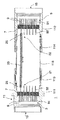
図1は、参照符号1で全体を示す本発明による電気リードスルーモジュールの一設計の実施形態の一部を断面図で示す。電気リードスルーモジュール1は、絶縁要素7を貫通して絶縁要素7の両側に突出する複数の導体9をそれぞれが有する2つの離間した電気リードスルー3、5から構成される。リードスルーモジュール1は、大電力用に設計されている。これに関連して、導体9の直径は少なくとも5mmである。絶縁要素7から突出している導体9の部分は、内部接続端92及び外部接続端91を形成し、2つの電気リードスルー3、5の導体9の内部接続端92は、互いに対向して配置される。
FIG. 1 shows, in cross-section, a portion of one design embodiment of an electrical lead-through module according to the present invention, indicated generally by the
絶縁要素7はそれぞれ、一方のリードスルー3、5の全導体に共通の絶縁要素として設計される。特に、この実施形態の絶縁要素は、リードスルーの導体9を互いに離間してシールするガラス絶縁材である。
Each of the
リードスルー3、5は、導体9の軸方向に互いに離間して配置され、管状要素11内に固定される。この管状要素11は、互いに接合される複数の部品111、112、113、114、115から構成され、部品111及び112は金属筐体を形成し、各筐体内にリードスルー3、5の1つ又は複数のガラス絶縁材7がシールされる。部品111、112、113、114は、例えば互いにねじ留め及び/又は互いに溶接され得る。管状要素内で2つのリードスルー間に形成される体積は密閉される。
The lead-
導体9の外部接続端91は、要素11の端子開口13、15を通してアクセス可能である。両側の外部接続端91をケーブル接続することで安全容器の内部で電気接続を確立するために、リードスルーモジュール1は、続いて開口13、15の一方が安全容器の内側からアクセス可能であり他方の開口が外側からアクセス可能であるように厚肉の圧力容器又は安全容器内に装着される。
The external connection end 91 of the
導体9に関して軸方向に離間している2つのリードスルー3、5の対向する導体9同士の相互接触は、本発明によれば、導体9に対して軸方向に変位可能であるように配置される接続要素としての導電棒20によって電気リードスルー3、5の導体9が互いに接続されることで得られる。軸方向のすなわち導体9に沿った変位性は、棒20に示す両矢印に基づいて示される。
According to the present invention, the mutual contact between the opposing
リードスルー3、5の対向する導体9の各対が、1つのこのような棒に接続される。しかしながら、簡単のために、図1は、2つの導体9を互いに接触させる個別の棒20を1つだけ示している。
Each pair of opposing
導体への棒20の軸方向に変位可能な取り付けは、レセプタクルコネクタによって行われる。そのため、棒20の2つの端21、22は、それぞれ1つのレセプタクル25を有し、レセプタクル25は、リードスルーモジュールの組み立て時に1つの導体9の内部接続端92に嵌められる。
The axially displaceable attachment of the
したがって、このようなリードスルーモジュールを製造するために、2つの電気リードスルー3、5が製造され、このとき、リードスルーのそれぞれが、絶縁要素が融着されて気密にシールされる少なくとも1つの軸方向開口を有するフランジを備え、絶縁要素7を貫通して絶縁要素7の両側に突出する複数の導体9が、絶縁要素7にシールされる。
Thus, to manufacture such a lead-through module, two electrical lead-
このとき、リードスルー3、5の配置は、電気リードスルー3、5の導体9が軸方向に見て対になって長手方向軸が整列して、リードスルーの少なくとも一方の導体に対して軸方向に変位可能に配置されている導電接続要素によって互いに電気的に接続されるようになっており、上記接続要素は、この場合はソケットコンタクトを有する導電棒の形態である。この場合、組み立て時に、2つのリードスルーは軸方向に一緒に移動して軸方向に離間して管状要素に固定され、このとき、隙間が気密にシールされることが好ましい。接合プロセス時に、棒のレセプタクルは導体9に沿って軸方向に変位する。
At this time, the arrangement of the lead-
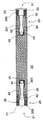
図2は、レセプタクル25を有するこのような棒20のより詳細な図を示す。棒20の両端に位置付けられているレセプタクルは、単体品の棒20の一体部分である。これに関連して、端子開口31を有する軸方向に延在する孔30が、棒20の端21、22に形成される。本発明のこの設計の実施形態では、棒20は、リードスルーの導体9の接触用の線ばねコンタクトを有する。この棒20では、導体9は、棒20の端21、22に位置付けられているレセプタクル25の線ばねコンタクトと接触する。
FIG. 2 shows a more detailed view of such a
レセプタクルはそれぞれ、軸方向に延在する孔30を備える。これらの孔は、開口31に通じる第1の部分300と、図2に示す実施形態では止まり孔として形成されている孔30の孔端まで延在する後続の部分301とを有する。環形のパウチ40内に、複数の線ばね42の各端が配置され、これらは、後方の部分301に延びて締め付け要素44によって孔30の内端に取り付けられる。締め付け要素44の取り付けは、例えば、締め付け要素44が拡張するように円錐ピンを締め付け要素44の開口45に押し込むことで、締め付け要素の挿入及び拡張によって行われ得る。線ばねが抜けるのを防止するために、代替的又は付加的に、短い管片35が孔30の部分300に装着され得る。
Each receptacle includes a
図3は、図2に示す棒20の変形形態を示す。この変形形態では、棒20は中実品ではなく、孔30が貫通している管として設計される。接触にはラメラコンタクト32が用いられる。
FIG. 3 shows a variation of the
図4は、図1に示す設計の実施形態の変形形態を示す。この変形形態では、2つのリードスルーは、接続要素としての棒によって接続されるのではなく、互いに電気的に直接接続される。これを行うために、リードスルー5の導体9には、2つのリードスルー3、5の導体9の電気接続部位にレセプタクル25としてばね接触要素が配置される。例えば、これらのレセプタクルは、図2に示す棒に対応する軸方向に変位可能な接続要素として設計され得る。リードスルー5の導体9に対して軸方向に離間して配置されているリードスルー3の導体9はそれぞれ、レセプタクル25の1つに軸方向に摺動可能に接触する。特に、レセプタクルはリードスルー5の導体9に組み込まれる。
FIG. 4 shows a variation of the embodiment of the design shown in FIG. In this variant, the two leadthroughs are not directly connected by a rod as a connecting element, but are electrically connected directly to each other. To do this, the
この設計は、短いリードスルーモジュールに特に適している。全ての設計の実施形態に共通するのは、最終的に組み立てられたリードスルーモジュールの2つのリードスルーが互いに対して所定位置に固定されるが、同じく組み立てられたリードスルーモジュールにおいて、リードスルーの少なくとも一方のリードスルー導体の1つの軸方向に摺動することができる導電接続要素によって、一方のリードスルーの1つのリードスルー導体が他方のリードスルーの1つのリードスルー導体と電気的に接触させられることである。 This design is particularly suitable for short lead-through modules. Common to all design embodiments is that the two leadthroughs of the final assembled leadthrough module are fixed in place relative to each other, but in the same assembled leadthrough module, An electrically conductive connecting element capable of sliding in one axial direction of at least one lead-through conductor causes one lead-through conductor of one lead-through to be in electrical contact with one lead-through conductor of the other lead-through. Is to be.
図1に示すリードスルーモジュールの設計の実施形態の要素11は、特定の用途に適合させた別の形状を有することもできるため、管状である必要はないことが、当業者には明らかである。また、本発明のさらなる設計の実施形態による2つのリードスルー3、5は、互いに直接接続することもできる。導体を囲んで導体の内部を密閉しているキャビティを作るために、リードスルー3、5の一方又は両方が帽子形であってもよい。このような例の1つを図5に示す。
It will be apparent to those skilled in the art that the
この実施形態では、リードスルー3は帽子形であるが、リードスルー5は本質的に円盤形のフランジとして設計される。帽子形のリードスルー3のクリンプ47は、リードスルー3とリードスルー5とを互いにねじ留めするのに用いる取り付けフランジを形成する。リングガスケット49が、密閉された隙間48の気密シールを確保する。軸方向に整列している導体9は、前の例のように、レセプタクル接続部を有することもでき、又は棒20に接続することもできる。図示の例では、代替物としてダブルレセプタクル50が用いられる。導体9は、例えば図2及び図3の例に示すように冠形に配置されている線ばね及び/又はラメラコンタクトの様式で、両側にレセプタクルを有し得る。
In this embodiment, the
当然ながら、本発明のこの設計の実施形態では、リードスルーは互いに直接設置されているが、この場合も前の例のように、接触導体の対が軸方向に離間している。 Of course, in this design embodiment of the present invention, the leadthroughs are placed directly on each other, but again, as in the previous example, the pairs of contact conductors are spaced apart in the axial direction.
図5に示すリードスルーモジュール1は特に、安全容器のフランジ開口の周りにフランジ接続するのに非常に適している。図5には、リードスルーモジュール1のフランジ5が安全容器53の接続フランジ52にフランジ接続される例が示されている。
The lead-through
本発明が上述の実施形態に制限されないことは、当業者には明らかである。実際、これらの実施形態は多くの方法で変更することができ、互いに組み合わせることができる。 It will be apparent to those skilled in the art that the present invention is not limited to the above-described embodiments. Indeed, these embodiments can be modified in many ways and combined with each other.
Claims (19)
Applications Claiming Priority (2)
| Application Number | Priority Date | Filing Date | Title |
|---|---|---|---|
| DE102007061174.0A DE102007061174B4 (en) | 2007-12-17 | 2007-12-17 | Electrical feedthrough module and method for its production, as well as pressure vessel or safety container feedthrough |
| DE102007061174.0 | 2007-12-17 |
Publications (2)
| Publication Number | Publication Date |
|---|---|
| JP2009145351A true JP2009145351A (en) | 2009-07-02 |
| JP5155133B2 JP5155133B2 (en) | 2013-02-27 |
Family
ID=40456227
Family Applications (1)
| Application Number | Title | Priority Date | Filing Date |
|---|---|---|---|
| JP2008320700A Active JP5155133B2 (en) | 2007-12-17 | 2008-12-17 | Electrical lead-through module and method of manufacturing the same |
Country Status (5)
| Country | Link |
|---|---|
| US (1) | US7927139B2 (en) |
| EP (1) | EP2073216B1 (en) |
| JP (1) | JP5155133B2 (en) |
| CN (1) | CN101465530A (en) |
| DE (1) | DE102007061174B4 (en) |
Cited By (2)
| Publication number | Priority date | Publication date | Assignee | Title |
|---|---|---|---|---|
| RU193452U1 (en) * | 2019-07-11 | 2019-10-30 | федеральное государственное бюджетное образовательное учреждение высшего образования "Нижегородский государственный технический университет им. Р.Е. Алексеева" (НГТУ) | Fast neutron nuclear power plant cooled by heavy liquid metal coolants of floating nuclear power plants, ships and ships |
| JP2020522864A (en) * | 2017-06-08 | 2020-07-30 | ストーブリ エレクトリカル コネクターズ アーゲー | Electrical connection element |
Families Citing this family (6)
| Publication number | Priority date | Publication date | Assignee | Title |
|---|---|---|---|---|
| DE202008001997U1 (en) * | 2008-02-14 | 2008-04-03 | Rosenberger Hochfrequenztechnik Gmbh & Co. Kg | contact spring |
| DE102010055177A1 (en) * | 2010-12-20 | 2012-06-21 | Schott Ag | Electrical feed-through assembly for implementing electrical connection through wall of reactor containment vessel in nuclear power plant, has electrical conductor and lines that are in contact with each other through connectors |
| DE102011003253A1 (en) * | 2011-01-27 | 2012-08-02 | Siemens Aktiengesellschaft | Feedthrough arrangement with an electrically insulating insulating element |
| DE102014204861A1 (en) * | 2014-03-17 | 2015-04-23 | Areva Gmbh | Electrical implementation |
| ITUB20152903A1 (en) | 2014-08-14 | 2017-02-05 | Schott Ag | Electric passage and its use |
| DE102022112386A1 (en) | 2022-05-17 | 2023-11-23 | Schott Ag | Flexible glass element and process for its production |
Citations (4)
| Publication number | Priority date | Publication date | Assignee | Title |
|---|---|---|---|---|
| JPH02133130U (en) * | 1989-04-06 | 1990-11-05 | ||
| JPH0360785U (en) * | 1989-10-17 | 1991-06-14 | ||
| JPH05161235A (en) * | 1991-12-06 | 1993-06-25 | Mitsubishi Cable Ind Ltd | Wire penetration apparatus |
| JP2007173198A (en) * | 2005-11-25 | 2007-07-05 | Hitachi Cable Ltd | Electric contact and female terminal |
Family Cites Families (14)
| Publication number | Priority date | Publication date | Assignee | Title |
|---|---|---|---|---|
| DE1490332A1 (en) * | 1962-09-06 | 1969-01-16 | Siemens Ag | Gas-tight lead-through of a shielded conductor through a metallic wall |
| DE1972545U (en) * | 1965-04-30 | 1967-11-16 | Jenaer Glaswerk Schott & Gen | ELECTRICAL FEEDTHROUGH. |
| BE788766A (en) * | 1971-09-23 | 1973-01-02 | Bunker Ramo | ELECTRICAL PASS-THROUGH ASSEMBLIES |
| JPS54788A (en) * | 1977-06-05 | 1979-01-06 | Kouenerugii Butsurigaku Kenkiy | Heatable vacuum terminal pin device |
| US4426124A (en) * | 1981-10-02 | 1984-01-17 | Hughes Tool Company | Feed through mandrel for submersible pump |
| US4540230A (en) * | 1983-12-27 | 1985-09-10 | Whittaker Corporation | Weatherproof hermetically sealed connector device |
| US4653839A (en) * | 1985-06-24 | 1987-03-31 | Itt Corporation | Connector with removable socket elements |
| US4854886A (en) * | 1986-09-29 | 1989-08-08 | Hubbell Incorporated | Electrical penetrator for hot, high pressure service |
| FR2637133B1 (en) | 1988-09-23 | 1991-06-14 | Merlin Gerin | EXPANSION JOINT OF A HIGH VOLTAGE ARMORED INSTALLATION |
| US5051103A (en) * | 1990-10-09 | 1991-09-24 | Hubbell Incorporated | Electrical coupling assembly for hot, high pressure service |
| DE4432982C2 (en) * | 1994-09-16 | 1998-07-09 | Igm Robotersysteme Ag | Device for irradiating surfaces with electrons |
| DE9419407U1 (en) | 1994-11-24 | 1995-02-02 | Siemens Ag | Compensator for an encapsulation housing |
| US6506069B2 (en) * | 2001-01-25 | 2003-01-14 | Kelsey-Hayes Company | Floating electrical connector for a pressure sensor |
| DE102006021621A1 (en) * | 2006-05-09 | 2007-11-15 | Linde Ag | Current feed-through device for high pressures and tempatures |
-
2007
- 2007-12-17 DE DE102007061174.0A patent/DE102007061174B4/en active Active
-
2008
- 2008-12-05 EP EP08021135.2A patent/EP2073216B1/en active Active
- 2008-12-16 US US12/335,622 patent/US7927139B2/en active Active
- 2008-12-17 JP JP2008320700A patent/JP5155133B2/en active Active
- 2008-12-17 CN CNA2008101856019A patent/CN101465530A/en active Pending
Patent Citations (4)
| Publication number | Priority date | Publication date | Assignee | Title |
|---|---|---|---|---|
| JPH02133130U (en) * | 1989-04-06 | 1990-11-05 | ||
| JPH0360785U (en) * | 1989-10-17 | 1991-06-14 | ||
| JPH05161235A (en) * | 1991-12-06 | 1993-06-25 | Mitsubishi Cable Ind Ltd | Wire penetration apparatus |
| JP2007173198A (en) * | 2005-11-25 | 2007-07-05 | Hitachi Cable Ltd | Electric contact and female terminal |
Cited By (2)
| Publication number | Priority date | Publication date | Assignee | Title |
|---|---|---|---|---|
| JP2020522864A (en) * | 2017-06-08 | 2020-07-30 | ストーブリ エレクトリカル コネクターズ アーゲー | Electrical connection element |
| RU193452U1 (en) * | 2019-07-11 | 2019-10-30 | федеральное государственное бюджетное образовательное учреждение высшего образования "Нижегородский государственный технический университет им. Р.Е. Алексеева" (НГТУ) | Fast neutron nuclear power plant cooled by heavy liquid metal coolants of floating nuclear power plants, ships and ships |
Also Published As
| Publication number | Publication date |
|---|---|
| DE102007061174B4 (en) | 2014-01-09 |
| US20090156040A1 (en) | 2009-06-18 |
| DE102007061174A1 (en) | 2009-06-18 |
| JP5155133B2 (en) | 2013-02-27 |
| EP2073216A1 (en) | 2009-06-24 |
| CN101465530A (en) | 2009-06-24 |
| US7927139B2 (en) | 2011-04-19 |
| EP2073216B1 (en) | 2020-06-24 |
Similar Documents
| Publication | Publication Date | Title |
|---|---|---|
| JP5155133B2 (en) | Electrical lead-through module and method of manufacturing the same | |
| EP2487758B1 (en) | Electrical connector for high-temperature environments | |
| KR101754140B1 (en) | Airtight coaxial connector | |
| JP2012119321A (en) | Cable terminator assembly | |
| US3861777A (en) | Separable electrical connector | |
| US20160134047A1 (en) | Structure for end of mi cable and method for producing the same | |
| CN102823068A (en) | Cable connection system and method for connecting a cable to a cable connection system | |
| EP3174165B1 (en) | Cable connector | |
| GB2491427A (en) | Explosion-resistant connector | |
| KR20170123618A (en) | How to assemble the inflection plug connector | |
| KR102277839B1 (en) | High voltage connector | |
| US20040089463A1 (en) | Coupling sleeve for a mineral-insulated cable and connection method | |
| US5616049A (en) | Connector assembly for metal-jacketed lambda probe conductor | |
| US9672962B2 (en) | Bushing of an electrical conductor | |
| US6250961B1 (en) | Hermetic connection assembly | |
| EP3828037A1 (en) | Arrangement for attaching an insulator sleeve to an electrical conductor | |
| US7683264B2 (en) | High pressure, high current, low inductance, high reliability sealed terminals | |
| US9601796B2 (en) | Fuel cell arrangement | |
| EP1811811A3 (en) | Cable and joint assembly | |
| JP6498615B2 (en) | 2-pole connector fitting structure | |
| CN112672445B (en) | Bushing, electric heating device and system having the bushing, and manufacturing method of the bushing | |
| RU136648U1 (en) | POWER ELECTRIC CONTACT | |
| JP5107095B2 (en) | Cable adapter | |
| US8297995B2 (en) | Device for preventing the establishment of an electric arc between two conductive elements | |
| RU2015114690A (en) | SEALED INPUT AND METHOD FOR ITS MANUFACTURE |
Legal Events
| Date | Code | Title | Description |
|---|---|---|---|
| A131 | Notification of reasons for refusal |
Free format text: JAPANESE INTERMEDIATE CODE: A131 Effective date: 20120215 |
|
| A521 | Request for written amendment filed |
Free format text: JAPANESE INTERMEDIATE CODE: A523 Effective date: 20120515 |
|
| TRDD | Decision of grant or rejection written | ||
| A01 | Written decision to grant a patent or to grant a registration (utility model) |
Free format text: JAPANESE INTERMEDIATE CODE: A01 Effective date: 20121108 |
|
| A61 | First payment of annual fees (during grant procedure) |
Free format text: JAPANESE INTERMEDIATE CODE: A61 Effective date: 20121206 |
|
| FPAY | Renewal fee payment (event date is renewal date of database) |
Free format text: PAYMENT UNTIL: 20151214 Year of fee payment: 3 |
|
| R150 | Certificate of patent or registration of utility model |
Ref document number: 5155133 Country of ref document: JP Free format text: JAPANESE INTERMEDIATE CODE: R150 Free format text: JAPANESE INTERMEDIATE CODE: R150 |
|
| R250 | Receipt of annual fees |
Free format text: JAPANESE INTERMEDIATE CODE: R250 |
|
| R250 | Receipt of annual fees |
Free format text: JAPANESE INTERMEDIATE CODE: R250 |
|
| R250 | Receipt of annual fees |
Free format text: JAPANESE INTERMEDIATE CODE: R250 |
|
| R250 | Receipt of annual fees |
Free format text: JAPANESE INTERMEDIATE CODE: R250 |
|
| R250 | Receipt of annual fees |
Free format text: JAPANESE INTERMEDIATE CODE: R250 |
|
| R250 | Receipt of annual fees |
Free format text: JAPANESE INTERMEDIATE CODE: R250 |
|
| R250 | Receipt of annual fees |
Free format text: JAPANESE INTERMEDIATE CODE: R250 |
|
| R250 | Receipt of annual fees |
Free format text: JAPANESE INTERMEDIATE CODE: R250 |
|
| R250 | Receipt of annual fees |
Free format text: JAPANESE INTERMEDIATE CODE: R250 |