EP2073216B1 - Electrical feedthrough module and method for producing same - Google Patents
Electrical feedthrough module and method for producing same Download PDFInfo
- Publication number
- EP2073216B1 EP2073216B1 EP08021135.2A EP08021135A EP2073216B1 EP 2073216 B1 EP2073216 B1 EP 2073216B1 EP 08021135 A EP08021135 A EP 08021135A EP 2073216 B1 EP2073216 B1 EP 2073216B1
- Authority
- EP
- European Patent Office
- Prior art keywords
- conductors
- axially
- rod
- feedthroughs
- electrical
- Prior art date
- Legal status (The legal status is an assumption and is not a legal conclusion. Google has not performed a legal analysis and makes no representation as to the accuracy of the status listed.)
- Active
Links
- 238000004519 manufacturing process Methods 0.000 title claims description 6
- 239000004020 conductor Substances 0.000 claims description 132
- 239000011521 glass Substances 0.000 claims description 17
- 238000007789 sealing Methods 0.000 claims description 3
- 239000007787 solid Substances 0.000 claims description 3
- 238000000034 method Methods 0.000 claims 2
- 238000009413 insulation Methods 0.000 description 32
- 241000446313 Lamella Species 0.000 description 4
- 230000008878 coupling Effects 0.000 description 4
- 238000010168 coupling process Methods 0.000 description 4
- 238000005859 coupling reaction Methods 0.000 description 4
- 238000011161 development Methods 0.000 description 3
- 230000018109 developmental process Effects 0.000 description 3
- 239000002184 metal Substances 0.000 description 3
- 238000005538 encapsulation Methods 0.000 description 2
- 230000007774 longterm Effects 0.000 description 2
- 238000005259 measurement Methods 0.000 description 2
- 229910000831 Steel Inorganic materials 0.000 description 1
- 230000001419 dependent effect Effects 0.000 description 1
- 230000001066 destructive effect Effects 0.000 description 1
- 230000006866 deterioration Effects 0.000 description 1
- 230000000694 effects Effects 0.000 description 1
- 229920001971 elastomer Polymers 0.000 description 1
- 239000000806 elastomer Substances 0.000 description 1
- 239000000156 glass melt Substances 0.000 description 1
- 238000010438 heat treatment Methods 0.000 description 1
- 238000009434 installation Methods 0.000 description 1
- 239000012774 insulation material Substances 0.000 description 1
- 230000005405 multipole Effects 0.000 description 1
- 230000003647 oxidation Effects 0.000 description 1
- 238000007254 oxidation reaction Methods 0.000 description 1
- 238000003825 pressing Methods 0.000 description 1
- 229920002379 silicone rubber Polymers 0.000 description 1
- 239000004945 silicone rubber Substances 0.000 description 1
- 239000010959 steel Substances 0.000 description 1
- 238000003466 welding Methods 0.000 description 1
Images


Classifications
-
- H—ELECTRICITY
- H02—GENERATION; CONVERSION OR DISTRIBUTION OF ELECTRIC POWER
- H02G—INSTALLATION OF ELECTRIC CABLES OR LINES, OR OF COMBINED OPTICAL AND ELECTRIC CABLES OR LINES
- H02G3/00—Installations of electric cables or lines or protective tubing therefor in or on buildings, equivalent structures or vehicles
- H02G3/22—Installations of cables or lines through walls, floors or ceilings, e.g. into buildings
-
- H—ELECTRICITY
- H01—ELECTRIC ELEMENTS
- H01R—ELECTRICALLY-CONDUCTIVE CONNECTIONS; STRUCTURAL ASSOCIATIONS OF A PLURALITY OF MUTUALLY-INSULATED ELECTRICAL CONNECTING ELEMENTS; COUPLING DEVICES; CURRENT COLLECTORS
- H01R13/00—Details of coupling devices of the kinds covered by groups H01R12/70 or H01R24/00 - H01R33/00
- H01R13/46—Bases; Cases
- H01R13/53—Bases or cases for heavy duty; Bases or cases for high voltage with means for preventing corona or arcing
-
- H—ELECTRICITY
- H01—ELECTRIC ELEMENTS
- H01R—ELECTRICALLY-CONDUCTIVE CONNECTIONS; STRUCTURAL ASSOCIATIONS OF A PLURALITY OF MUTUALLY-INSULATED ELECTRICAL CONNECTING ELEMENTS; COUPLING DEVICES; CURRENT COLLECTORS
- H01R13/00—Details of coupling devices of the kinds covered by groups H01R12/70 or H01R24/00 - H01R33/00
- H01R13/02—Contact members
- H01R13/15—Pins, blades or sockets having separate spring member for producing or increasing contact pressure
- H01R13/187—Pins, blades or sockets having separate spring member for producing or increasing contact pressure with spring member in the socket
-
- Y—GENERAL TAGGING OF NEW TECHNOLOGICAL DEVELOPMENTS; GENERAL TAGGING OF CROSS-SECTIONAL TECHNOLOGIES SPANNING OVER SEVERAL SECTIONS OF THE IPC; TECHNICAL SUBJECTS COVERED BY FORMER USPC CROSS-REFERENCE ART COLLECTIONS [XRACs] AND DIGESTS
- Y10—TECHNICAL SUBJECTS COVERED BY FORMER USPC
- Y10S—TECHNICAL SUBJECTS COVERED BY FORMER USPC CROSS-REFERENCE ART COLLECTIONS [XRACs] AND DIGESTS
- Y10S439/00—Electrical connectors
- Y10S439/933—Special insulation
- Y10S439/935—Glass or ceramic contact pin holder
-
- Y—GENERAL TAGGING OF NEW TECHNOLOGICAL DEVELOPMENTS; GENERAL TAGGING OF CROSS-SECTIONAL TECHNOLOGIES SPANNING OVER SEVERAL SECTIONS OF THE IPC; TECHNICAL SUBJECTS COVERED BY FORMER USPC CROSS-REFERENCE ART COLLECTIONS [XRACs] AND DIGESTS
- Y10—TECHNICAL SUBJECTS COVERED BY FORMER USPC
- Y10T—TECHNICAL SUBJECTS COVERED BY FORMER US CLASSIFICATION
- Y10T29/00—Metal working
- Y10T29/53—Means to assemble or disassemble
- Y10T29/5313—Means to assemble electrical device
- Y10T29/532—Conductor
- Y10T29/53209—Terminal or connector
Definitions
- the invention relates generally to electrical feedthroughs, in particular electrical feedthroughs for pressure or safety containers, motor entries, housing entries and container entries.
- electrical feedthroughs and feedthrough modules are often used in this area have spaced, interconnected electrical feedthroughs one behind the other with one or more conductors through an insulation body.
- the bushings are held in a carrier body, generally made of metal, but also made of plastic. In general, two such bushings are used, which are spaced and wired together.
- GB-A-2 198 295 describes an electrical coupling device between areas of different air pressure. The through-connection takes place via suitable coupling elements which are introduced into a cylindrical tube. Appropriate elements prevent pressure equalization between the two pressure areas from occurring.
- An electrode leadthrough is described, for example, for energy, measurement and control lines in the interior of large containers, for example atomic reactors, the tightness of which can be monitored continuously or at intervals.
- a tube made of steel is sealed on both sides with a single- or multi-pole disk-shaped bushings in a vacuum-tight manner.
- a nozzle is provided through which the inside of the pipe can be evacuated and to which devices for measuring the values of the negative pressure can be connected.
- Two rods are inserted into a cylindrical tube.
- One of the rods has a claw-shaped cavity.
- the second rod can be moved in a longitudinally elastic manner along the longitudinal axis of this cavity.
- a plug device which establishes an electrical connection between a conductor of a plug and a conductor of a socket.
- the conductors can be inserted into conductive pins that are connected to each other via an electrically conductive lining.
- connection plate contains feedthrough openings with connection feedthroughs made of silicone rubber, in which conductive connection contacts are arranged. The opposite ends of these connection contacts each receive coupling connections between which electrical feedthrough connections are to be made.
- the invention is therefore based on the object of providing a bushing module in which the conductors of the bushings are securely connected to one another and in which the connection is easier to carry out.
- the invention provides an electrical bushing module, comprising at least two axially spaced, mutually fixed electrical bushings, each with a plurality of conductors which are passed through an insulation body and protrude on both sides of the insulation body.
- the insulation body is designed as a common insulation body for all conductors of a respective bushing.
- the conductors are axially spaced and in each case a conductor of a double guide is electrically connected to a conductor of a further implementation with a rod.
- the conductors of the electrical bushings are electrically connected to one another with a connecting element which is arranged to be axially displaceable relative to the conductors of at least one of the bushings.
- the connecting element comprises an electrically conductive rod which is axially displaceable with respect to the conductors and which at its ends each has a socket designed as an integral part of the rod.
- the conductors of the electrical bushings are aligned in pairs, viewed in the axial direction, with their longitudinal axes, and two of these axially aligned conductors are electrically connected by the axially displaceable rod.
- the rod is thus formed as an integral part of the rod.
- the rod is in one piece formed with end openings to the axially extending holes, in which the contact element or elements of the socket are arranged.
- the method for producing such a lead-through module is accordingly based on the fact that at least two axially spaced, mutually fixed electrical lead-throughs, each having a plurality of conductors which pass through an insulation body and protrude on both sides of the insulation body, are electrically connected to one another with a connecting element which is arranged axially displaceably to the conductors, the insulation body being designed as a common insulation body for all conductors of a respective bushing.
- the conductors are axially spaced apart and in each case one conductor of a bushing is electrically connected to a conductor of another bushing with a rod.
- the connecting element comprises an electrically conductive rod which is axially displaceable relative to the conductors and which at its ends each has a socket designed as an integral part of the rod.
- the conductors of the electrical bushings are aligned in pairs in the axial direction with their longitudinal axes, and two of these axially aligned conductors are electrically connected by the axially displaceable rod.
- the socket is thus formed as an integral part of the rod.
- the rod is formed in one piece with end openings to the axially extending holes, in which the contact element or elements of the socket are arranged.
- the electrical feedthrough module is preferably constructed as follows: at least two electrical feedthroughs are provided, each of the feedthroughs comprising a flange with at least one axial opening, into which a glass insulation body is melted in a hermetically sealing manner, with conductors melted into the glass insulation body are provided, wherein the electrical contact is made in each case with a socket contact, and wherein an intermediate space surrounding the connecting element is hermetically enclosed between the insulating bodies.
- the corresponding method for producing such a feedthrough is based on producing at least two electrical feedthroughs, each of the feedthroughs comprising a flange with at least one axial opening, into which a glass insulation body is melted in a hermetically sealed manner, in each case several through the glass insulation body passed and protruding on both sides of the insulation body are melted into the glass insulation body, and the bushings are arranged so that the conductors of the electrical bushings are viewed in pairs in the axial direction with their longitudinal axes aligned and with one axially to the conductors at least one of the Feedthroughs are arranged in a displaceably arranged electrically conductive connecting element, each with a socket contact, and the two leadthroughs are brought together in the axial direction during assembly, and the electrically conductive connecting elements move in the axial direction along the conductors contacted by the connecting elements, the leadthroughs being axial are attached at a distance, so that an intermediate space surrounding the connecting elements is hermetically enclosed between the insul
- a single glass insulation body can be provided per conductor, or several conductors can be melted into a common insulation body.
- the conductors of both bushings can each have a socket in which a rod is held as an axially displaceable connecting element.
- the rods can also be dispensed with, depending on the length of the feed-through module.
- a Feed-through conductor at the connection point is designed as a socket contact with a resilient contact element and the conductor contacts the second bushings, which are in particular axially spaced axially from the feed-through conductor, in this bush in an axially sliding manner.
- the bushing module according to the invention is particularly suitable for carrying out higher electrical powers, in particular for high current and / or medium voltage.
- the conductors of the bushings each have a diameter of at least 5 millimeters.
- screwed or crimped contacts have been used for electrical feedthroughs in safety containers for reasons of operational safety.
- a screw connection or a crimped connection ensures long-term electrical contact with a low level Resistance.
- a noticeable contact resistance would lead to strong heating, which in turn increases the contact resistance.
- An unsafe electrical contact can quickly lead to failure of the bushing.
- ring-shaped or basket-shaped, resilient contact elements are provided.
- the individual spring elements are arranged in such a way that a large number of contact points are produced along an annular contact area.
- the sockets can first be fastened on the conductors of one of the bushings and then the conductors of the further bushing can be contacted with the sockets in one step by being axially pushed on.
- a rod as connecting element can also have a socket on at least one of its ends.
- a conductor of the bushing already has such an integrated socket. In any case, in all of these cases a connection to at least one of the conductors is established by means of a socket connection.
- bushings are spaced apart from one another in the axial direction of the conductor in order to enable installation in a container wall, so that the conductor or conductors of one bushing are accessible from the outside and the conductor or bushings of a further bushing inside the container are.
- the connecting element has two ends with sockets, or at least one of the conductors which are electrically connected to one another is designed as a socket and the other conductor is immersed in the socket body, so that the conductor connection both bushings can be made permanently and safely with a socket connection.
- a socket connection also allows the rod to move in the axial direction. With such a connection, the displaceability of the rod in this direction is made possible.
- the axial displaceability is particularly advantageous in order to allow temperature-related changes in length of the rod arranged between the bushings without exerting tensile or compressive loads on the bushings to be connected.
- a particularly advantageous side effect is that the length changes do not always contact the same points on the conductor, but that the contact points also shift slightly in the axial direction. This also prevents over a long period of time that deterioration or even interruption of the electrical contact between the conductor of the bushing and the electrical connection according to the invention made with the rigid rod to a conductor of the other bushing can occur due to oxidation of the conductor surfaces.
- the socket is arranged in an axially extending hole at the end of the rod.
- the socket can be special advantageously be formed as an integral part of the rod. This means in particular that no separate socket part is placed on the rod, but that the rod is formed in one piece with end openings to the axially extending holes in which the contact element or elements are arranged.
- rod does not exclusively refer to a solid object in the sense of the invention. Rather, the term rod is also generally to be understood as a rigid connecting element. According to a further development of the invention, such a connecting element can also be designed as a tube or rod or comprise a tube or rod or several such tubular or rod-shaped elements.
- Longitudinally displaceable contacts in particular also in connection with sockets, can advantageously be achieved by contacting the connecting element with the conductor by means of a lamella contact and / or a wire spring contact.
- Both contacts can in particular, as mentioned above, be configured in the form of a ring or a basket, in order to also be well suited for carrying out high electrical outputs.
- the insulation bodies of the bushings can be connected to a tubular body.
- a firm connection between the feedthroughs is created, with one or more rods running protected inside the tubular body between the conductors.
- the assembly of the electrical feedthrough module is made easier if the tubular body is composed of several parts which are connected to one another.
- the connection can be made by screwing and / or welding.
- the bushings each have a plurality of conductors, the conductors being guided and supported at least in one of the bushings by a common insulation body. This enables a very dense arrangement of the conductors. Because of the contacting according to the invention by rods, which are in particular simply plugged onto the conductors no problems arise when assembling the electrical feedthrough module even with a dense arrangement.
- the insulation bodies each comprise glass insulation, into which the at least one conductor of the bushing is melted during manufacture.
- Glass as insulation material is particularly long-term, hermetically sealed and temperature-resistant.
- the glass insulation is preferably further melted in a metal frame.
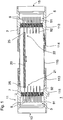
- Fig. 1 shows a cross-sectional view of parts of an embodiment of an electrical feed-through module according to the invention, designated as a whole by reference number 1.
- the electrical feed-through module 1 comprises two spaced-apart electrical feedthroughs 3, 5, each with a plurality of conductors 9 which are guided through an insulation body 7 and protrude on both sides of the insulation body 7.
- the conductors 9 have a diameter of at least 5 millimeters.
- the parts of the conductor 9 protruding from the insulation body 7 form inside connection ends 92 and outside connection ends 91, the inside connection ends 92 of the conductors 9 of the two electrical feedthroughs 3, 5 being arranged opposite and facing one another.
- the insulation bodies 7 are each a common insulation body for all conductors of a bushing 3, 5 educated.
- the insulation bodies in this example are glass insulation into which the conductors 9 of the bushings are melted at a distance from one another.
- the bushings 3, 5 are fastened in a tubular body 11 spaced apart from one another in the axial direction of the conductors 9.
- This tubular body 11 is composed of several interconnected parts 111, 112, 113, 114, 115, the parts 111 and 112 forming metal sockets into which one or more glass insulation 7 of the bushings 3, 5 is melted.
- the parts 111, 112, 113, 114 can for example be screwed together and / or welded.
- the volume formed between the two bushings in the tubular body is hermetically sealed.
- the outer connection ends 91 of the conductors 9 are accessible via the end openings 13, 15 of the body 11.
- the feed-through module 1 is then installed in a thick-walled pressure container or safety container in such a way that one of the openings 13, 15 within the safety container and the other opening is accessible from the outside in order to be able to wire the outer connection ends 91 on both sides and thus electrical connections to the inside of the containment.
- the contact between respectively opposite conductors 9 of the two bushings 3, 5 axially spaced with respect to the conductor 9 is achieved according to the invention in that the conductors 9 of the electrical bushings 3, 5 are connected to one another with an electrically conductive rod 20 arranged axially displaceably relative to the conductors 9 as a connecting element are.
- the displaceability in the axial direction or along the conductor 9 is indicated by the double arrow drawn in the rod 20.
- Each pair of opposite conductors 9 of the bushings 3, 5 is connected to such a rod.
- Fig. 1 only a single rod 20 is shown, which contacts two conductors 9 with one another.
- the axially displaceable fastening of the rod 20 to the conductors takes place by means of socket connections.
- the two ends 21, 22 of the rod 20 each have a socket 25, which is plugged onto the inner connection end 92 of a conductor 9 when the bushing module is assembled.
- each of the lead-throughs comprising a flange with at least one axial opening, into which the insulating body is melted in a hermetically sealed manner, with several leading through the insulating body 7 and on both sides of the insulation body 7 protruding conductor 9 are melted into the insulation body 7.
- the bushings 3, 5 are then arranged such that the conductors 9 of the electrical bushings 3, 5, viewed in pairs in the axial direction, are aligned with their longitudinal axes and with at least one of the bushings 3, 5 axially displaceably arranged electrically conductive connecting element, here be electrically connected to each other in the form of the conductive rods with socket contacts.
- the two bushings are brought together in the axial direction and fastened axially spaced on the tubular body, the space preferably being hermetically sealed.
- the sockets of the rods are moved in the axial direction along the conductor 9.
- Fig. 2 a more detailed view of such a rod 20 with sockets 25 is shown.
- the sockets arranged at both ends of the rod 20 are integrally formed in the one-piece rod 20.
- axially extending holes 30 with end openings 31 are inserted into the ends 21, 22 of the rod 20.
- the rod 20 has wire spring contacts for contacting the conductors 9 of the bushings. With this rod 20, the conductors 9 are contacted with the wire spring contacts of the sockets 25 arranged at the ends 21, 22 of the rod 20.
- the sockets each comprise axially extending holes 30. These holes have a first section 300 opening into the opening 31 and an adjoining section 301 which, up to the hole end, is the same as in FIG Fig. 2 Example shown as blind holes 30 is sufficient.
- ends of a plurality of wire springs 42 are received, which extend into the rear section 301 and are fixed at the inner end of the hole 30 with a clamping element 44.
- the clamping element 44 can be fixed, for example, by inserting and expanding the clamping element 44, by pressing a conical plunger into the opening 45 of the clamping element 44, so that the clamping element expands.
- a short tube piece 35 can alternatively or additionally be inserted into the section 300 of the hole 30.
- Fig. 3 shows a variant of the in Fig. 2 Rod 20 shown.
- the rod 20 is not solid, but rather as a tube with a through hole 30.
- lamella contacts 32 are used.
- Fig. 4 shows an unclaimed variant of the in Fig. 1 shown embodiment.
- the two bushings are not electrically connected to each other via a rod as a connecting element, but directly.
- the conductors 9 of the bushing 5 at the electrical connection point of the conductors 9 of the two bushings 3, 5 are designed as sockets 25 with a resilient contact element.
- these sockets can be used as axially movable connecting elements corresponding to those in FIG Fig. 2 shown rod may be formed.
- the conductors 9 are axially spaced axially from the conductors 9 of the bushing 5 arranged bushings 3 are in each case axially slidably contacted in one of the sockets 25.
- the sockets are integrated in the conductor 9 of the bushing 5.
- This design is particularly suitable for shorter bushing modules. All embodiments have in common that the two bushings are fixed to one another in the assembled bushing module, but also in the assembled bushing module an bushing conductor of a bushing with a bushing conductor of the other bushing electrically via at least one of the bushings being able to slide in the axial direction of an bushing conductor is contacted.
- body 11 of the type shown in FIG Fig. 1 Embodiment of a feed-through module shown can also have a different shape adapted to the respective application, that is, it need not be tubular.
- the two bushings 3, 5 can also be connected directly to one another.
- one or both of the bushings 3, 5 can be hat-shaped.
- Such an example shows Fig. 5 .
- the bushing 3 is hat-shaped, while the bushing 5 is designed as an essentially disk-shaped flange.
- the brim 47 of the hat-shaped bushing 3 forms a fastening flange with which the bushing 3 is screwed to the bushing 5.
- An annular seal 49 ensures a hermetic seal of the enclosed space 48.
- the axially aligned conductors 9 themselves can have a plug connection or can be connected to a rod 20.
- double sockets 50 were alternatively used. These can be, for example, sockets on both sides of the type in the 2 and 3 have examples shown with ring-shaped wire springs and / or lamella contacts.
- the bushings are placed directly on top of one another, but here too, as in the previous examples, the conductors contacted in pairs are spaced apart in the axial direction.
- Feedthrough module 1 shown is well suited, among other things, to be flanged to flange openings of security containers. Is shown in Fig. 5 an example in which the flange 5 of the lead-through module 1 is flanged to the connection flange 52 of a security container 53.
Description
Die Erfindung betrifft allgemein elektrische Durchführungen, insbesondere elektrische Durchführungen für Druck- bzw. Sicherheitsbehälter, Motoreinführungen, Gehäuseeinführungen und Behältereinführungen.The invention relates generally to electrical feedthroughs, in particular electrical feedthroughs for pressure or safety containers, motor entries, housing entries and container entries.
Um höchste Anforderungen bei der Betriebssicherheit von Sicherheitsbehältern, wie beispielsweise von Reaktorsicherheitsbehältern oder anderen Druckbehältern und sonstigen Stromeinführungen zur Stromversorgung und Durchführung von Steuer- und Meßsignalen zu erfüllen, werden in diesem Bereich vielfach elektrische Durchführungen und Durchführungsmodule verwendet, die bei erhöhten Sicherheitsanforderungen zwei oder mehrere voneinander beabstandete, miteinander verkabelte elektrische Durchführungen hintereinander mit einem oder mehreren durch einen Isolationskörper durchgeführten Leitern aufweisen. Die Durchführungen werden in einem Trägerkörper, im allgemeinen aus Metall, jedoch auch aus Kunststoff gehalten. Im allgemeinen werden dabei zwei solcher Durchführungen verwendet, die beabstandet und miteinander verkabelt sind.
In der Druckschrift
In der Druckschrift
In the publication
In the publication
In der Druckschrift
In der Druckschrift
In der Druckschrift
Aus derFrom the
Aus derFrom the
Bisher wurden die Leiter der elektrischen Durchführungen solcher Durchführungsmodule mittels Kabel elektrisch miteinander verbunden. Um die Kabel an die Leiter der Durchführungen anzuschließen, wurden dann Crimp- und Schraub-Verbindungen eingesetzt. Diese Verbindungsweise weist jedoch mehrere Nachteile auf. Das Verbinden ist fehlerträchtig, beansprucht sehr viel Platz und ist vor allem zerstörungsfrei nicht mehr lösbar. Crimp-Hülse und Kabel müssen exakt aufeinander abgestimmt sein. Weiterhin ist diese Art der elektrischen Kontaktierung der Leiter auch sehr aufwendig und arbeitsintensiv. Dies ist insbesondere dann nicht unerheblich, wenn ein solches Durchführungsmodul, was durchaus üblich ist, weit über hundert Anschlüsse aufweist, bei welchen die Leiter jeweils miteinander zu verbinden sind.So far, the conductors of the electrical bushings of such bushing modules have been electrically connected to one another by means of cables. Crimp and screw connections were then used to connect the cables to the conductors. However, this type of connection has several disadvantages. The connection is prone to errors, takes up a lot of space and, above all, is no longer non-destructive. Crimp sleeve and cable must be exactly matched. Furthermore, this type of electrical contacting of the conductors is also very complex and labor-intensive. This is not insignificant in particular if such a bushing module, which is quite common, has well over a hundred connections at which the conductors are to be connected to one another.
Der Erfindung liegt daher die Aufgabe zugrunde, ein Durchführungsmodul bereitzustellen, bei welchen die Leiter der Durchführungen sicher miteinander verbunden sind und bei welcher das Verbinden einfacher vorzunehmen ist.The invention is therefore based on the object of providing a bushing module in which the conductors of the bushings are securely connected to one another and in which the connection is easier to carry out.
Diese Aufgabe wird bereits in höchst überraschend einfacher Weise durch den Gegenstand der unabhängigen Ansprüche gelöst. Vorteilhafte Ausgestaltungen und Weiterbildungen sind in den abhängigen Ansprüchen angegeben. Demgemäß sieht die Erfindung ein elektrisches Durchführungsmodul, umfassend zumindest zwei axial beabstandete,zueinander fixierte elektrische Durchführungen mit jeweils mehreren durch einen Isolationskörper hindurchgeführten und auf beiden Seiten des Isolationskörpers herausragenden Leiter vor. Hierbei ist der Isolationskörper als gemeinsamer Isolationskörper für alle Leiter einer jeweiligen Durchführung ausgebildet. Die Leiter sind axial beabstandet und jeweils ein Leiter einer Ducrhjführung wird mit einem Leiter einer weiteren Durchführung mit einer Stange elektrisch verbunden. Die Leiter der elektrischen Durchführungen sind mit einem axial zu den Leitern zumindest einer der Durchführungen verschiebbar angeordneten Verbindungselement elektrisch miteinander verbunden. Das Verbindungselement umfasst eine gegenüber den Leitern axial verschiebbare, elektrisch leitende Stange, die an ihren Enden jeweils eine als integraler Bestandteil der Stange ausgebildete Steckbuchse auf. Hierbei fluchten die Leiter der elektrischen Durchführungen paarweise in axialer Richtung betrachtet mit ihren Längsachsen und durch die axial verschiebbare Stange sind zwei dieser axial fluchtenden Leiter elektrisch verbunden. Die Stange ist dadurch als integraler Bestandteil der Stange ausgebildet. Die Stange ist einstückig mit endseitigen Öffnungen zu den axial verlaufenden Löchern ausgebildet, in welchen das oder die Kontaktelemente der Steckbuchse angeordnet sind.This object is already achieved in a surprisingly simple manner by the subject matter of the independent claims. Advantageous refinements and developments are specified in the dependent claims. Accordingly, the invention provides an electrical bushing module, comprising at least two axially spaced, mutually fixed electrical bushings, each with a plurality of conductors which are passed through an insulation body and protrude on both sides of the insulation body. Here, the insulation body is designed as a common insulation body for all conductors of a respective bushing. The conductors are axially spaced and in each case a conductor of a double guide is electrically connected to a conductor of a further implementation with a rod. The conductors of the electrical bushings are electrically connected to one another with a connecting element which is arranged to be axially displaceable relative to the conductors of at least one of the bushings. The connecting element comprises an electrically conductive rod which is axially displaceable with respect to the conductors and which at its ends each has a socket designed as an integral part of the rod. Here, the conductors of the electrical bushings are aligned in pairs, viewed in the axial direction, with their longitudinal axes, and two of these axially aligned conductors are electrically connected by the axially displaceable rod. The rod is thus formed as an integral part of the rod. The rod is in one piece formed with end openings to the axially extending holes, in which the contact element or elements of the socket are arranged.
Das Verfahren zur Herstellung eines solchen Durchführungsmoduls basiert dementsprechend darauf, dass zumindest zwei axial beabstandete, zueinander fixierte elektrische Durchführungen mit jeweils mehreren durch einen Isolationskörper hindurchgeführten und auf beiden Seiten des Isolationskörpers herausragenden Leiter mit einem axial zu den Leitern verschiebbar angeordneten Verbindungselement elektrisch miteinander verbunden werden, wobei der Isolationskörper als gemeinsamer Isolationskörper für alle Leiter einer jeweiligen Durchführung ausgebildet ist.. Die Leiter sind hierbei axial beabstandet und jeweils ein Leiter einer Durchführung wird mit einem Leiter einer weiteren Durchführung mit einer Stange elektrisch verbunden. Das Verbindungselement umfasst eine gegenüber den Leitern axial verschiebbare, elektrisch leitende Stange, die an ihren Enden jeweils eine als integraler Bestandteil der Stange ausgebildete Steckbuchse aufweist. Die Leiter der elektrischen Durchführungen fluchten paarweise in axialer Richtung betrachtet mit ihren Längsachsen und durch die axial verschiebbare Stange werden zwei dieser axial fluchtenden Leiter elektrisch verbunden. Die Steckbuchse ist dadurch als integraler Bestandteil der Stange ausgebildet. Die Stange ist einstückig mit endseitigen Öffnungen zu den axial verlaufenden Löchern ausgebildet, in welchen das oder die Kontaktelemente der Steckbuchse angeordnet sind.The method for producing such a lead-through module is accordingly based on the fact that at least two axially spaced, mutually fixed electrical lead-throughs, each having a plurality of conductors which pass through an insulation body and protrude on both sides of the insulation body, are electrically connected to one another with a connecting element which is arranged axially displaceably to the conductors, the insulation body being designed as a common insulation body for all conductors of a respective bushing. The conductors are axially spaced apart and in each case one conductor of a bushing is electrically connected to a conductor of another bushing with a rod. The connecting element comprises an electrically conductive rod which is axially displaceable relative to the conductors and which at its ends each has a socket designed as an integral part of the rod. The conductors of the electrical bushings are aligned in pairs in the axial direction with their longitudinal axes, and two of these axially aligned conductors are electrically connected by the axially displaceable rod. The socket is thus formed as an integral part of the rod. The rod is formed in one piece with end openings to the axially extending holes, in which the contact element or elements of the socket are arranged.
Im Speziellen ist das elektrische Durchführungsmodul vorzugsweise folgendermassen aufgebaut: Es sind zumindest zwei elektrische Durchführungen vorgesehen, wobei jede der Durchführungen einen Flansch mit zumindest einer axialen Öffnung umfasst, in welche hermetisch dichtend ein Glas-Isolationskörper eingeschmolzen ist, wobei in den Glas-Isolationskörper eingeschmolzene Leiter vorgesehen sind, , wobei die elektrische Kontaktierung mit jeweils einem Buchsenkontakt hergestellt ist, und wobei zwischen den Isolationskörpern ein das Verbindungselement umgebender Zwischenraum hermetisch eingeschlossen ist.In particular, the electrical feedthrough module is preferably constructed as follows: at least two electrical feedthroughs are provided, each of the feedthroughs comprising a flange with at least one axial opening, into which a glass insulation body is melted in a hermetically sealing manner, with conductors melted into the glass insulation body are provided, wherein the electrical contact is made in each case with a socket contact, and wherein an intermediate space surrounding the connecting element is hermetically enclosed between the insulating bodies.
Das entsprechende Verfahren zur Herstellung einer solchen Durchführung basiert darauf, zumindest zwei elektrische Durchführungen herzustellen, wobei jede der Durchführungen einen Flansch mit zumindest einer axialen Öffnung umfasst, in welche hermetisch dichtend ein Glas-Isolationskörper eingeschmolzen wird, wobei jeweils mehrere durch den Glas-Isolationskörper hindurchgeführte und auf beiden Seiten des Isolationskörpers herausragende Leiter in die Glas-Isolationskörper eingeschmolzen werden, und wobei die Durchführungen so angeordnet werden, dass die Leiter der elektrischen Durchführungen paarweise in axialer Richtung betrachtet mit ihren Längsachsen fluchten und mit einem axial zu den Leitern zumindest einer der Durchführungen verschiebbar angeordneten elektrisch leitenden Verbindungselement mit jeweils einem Buchsenkontakt elektrisch miteinander verbunden werden, und wobei beim Zusammenbau die beiden Durchführungen in axialer Richtung zusammengeführt werden, und dabei die elektrisch leitenden Verbindungselemente sich in axialer Richtung entlang der durch die Verbindungselemente kontaktierten Leitern verschieben wobei die Durchführungen axial beabstandet befestigt werden, so dass zwischen den Isolationskörpern ein die Verbindungselemente umgebender Zwischenraum hermetisch eingeschlossen wird. Durch die axial verschiebbaren Kontakte ist kein besonderer Aufwand bei der Kontaktierung der Leiter mehr erforderlich. Vielmehr werden die Durchführungen so zusammengesetzt, dass die Leiter axial fluchten und dabei der elektrische Kontakt durch die Steckbuchsen hergestellt wird. Die Kontaktierung erfolgt somit gleichzeitig mit dem Zusammensetzen der Durchführungen.The corresponding method for producing such a feedthrough is based on producing at least two electrical feedthroughs, each of the feedthroughs comprising a flange with at least one axial opening, into which a glass insulation body is melted in a hermetically sealed manner, in each case several through the glass insulation body passed and protruding on both sides of the insulation body are melted into the glass insulation body, and the bushings are arranged so that the conductors of the electrical bushings are viewed in pairs in the axial direction with their longitudinal axes aligned and with one axially to the conductors at least one of the Feedthroughs are arranged in a displaceably arranged electrically conductive connecting element, each with a socket contact, and the two leadthroughs are brought together in the axial direction during assembly, and the electrically conductive connecting elements move in the axial direction along the conductors contacted by the connecting elements, the leadthroughs being axial are attached at a distance, so that an intermediate space surrounding the connecting elements is hermetically enclosed between the insulating bodies. Due to the axially displaceable contacts, no special effort is required when contacting the conductors. Rather, the bushings are assembled so that the conductors are axially aligned and the electrical contact is made through the sockets. The contact is thus made simultaneously with the assembly of the bushings.
Generell kann ein einzelner Glas-Isolationskörper pro Leiter vorgesehen sein, oder auch mehrere Leiter in einen gemeinsamen Isolationskörper eingeschmolzen werden.In general, a single glass insulation body can be provided per conductor, or several conductors can be melted into a common insulation body.
Indem die Leiter der mit einer axial zu den Leitern verschiebbar angeordneten Stange elektrisch miteinander unter Abstand zueinander verbunden werden, wird eine gleich stabile Anordnung verglichen mit den bisher üblichen Kabeln erreicht. Auch kann die Verbindung der Leiter mit den Stangen deutlich einfacher und platzsparender hergestellt werden. Dies gilt insbesondere für solche elektrischen Durchführungen mit mehreren elektrischen Leitern. Wird eine Stange als Verbindungselement eingesetzt, können auch der oder die Leiter der Durchführungen ein- oder beidseitig mit Steckbuchsen versehen sein, in welchen die Stange axial verschiebbar gehaltert wird. Insbesondere können dabei die Leiter beider Durchführungen jeweils eine Steckbuchse aufweisen, in welchen eine Stange als axial verschiebbares Verbindungselement gehaltert ist.By electrically connecting the conductors to one another at a distance from one another with a rod which is axially displaceable relative to the conductors, an arrangement which is equally stable is achieved in comparison with the cables customary hitherto. The connection of the ladder to the rods can also be made much easier and space-saving. This applies particularly to such electrical feedthroughs with several electrical conductors. If a rod is used as a connecting element, the conductor or conductors of the bushings can also be provided on one or both sides with sockets in which the rod is held so as to be axially displaceable. In particular, the conductors of both bushings can each have a socket in which a rod is held as an axially displaceable connecting element.
Gemäß einer weiteren Ausführungsform der Erfindung kann auf die Stangen auch, je nach Länge des Durchführungsmoduls, verzichtet werden. Dazu ist vorgesehen, daß ein Durchführungsleiter an der Verbindungsstelle als Buchsenkontakt mit federndem Kontaktelement ausgeführt ist und der Leiter der insbesondere axial zum Durchführungsleiter axial beabstandet angeordneten zweiten Durchführungen in dieser Buchse axial gleitend kontaktiert.According to a further embodiment of the invention, the rods can also be dispensed with, depending on the length of the feed-through module. It is provided that a Feed-through conductor at the connection point is designed as a socket contact with a resilient contact element and the conductor contacts the second bushings, which are in particular axially spaced axially from the feed-through conductor, in this bush in an axially sliding manner.
Das erfindungsgemäße Durchführungsmodul ist besonders für die Durchführung höherer elektrischer Leistungen, insbesondere für Starkstrom und/oder Mittelspannung geeignet. Dazu weisen die Leiter der Durchführungen jeweils einen Durchmesser von zumindest 5 Millimetern auf.The bushing module according to the invention is particularly suitable for carrying out higher electrical powers, in particular for high current and / or medium voltage. For this purpose, the conductors of the bushings each have a diameter of at least 5 millimeters.
Bisher wurden für elektrische Durchführungen bei Sicherheitsbehältern aus Gründen der Betriebssicherheit verschraubte oder vercrimpte Kontakte eingesetzt. Besonders bei Durchführungen, die für hohe Ströme ab 10 Ampére, und/oder Mittelspannung (üblicherweise werden als Mittelspannung Spannungen im Bereich von 1 bis 30 kV bezeichnet) ausgelegt sind, gewährleistet eine Verschraubung oder eine gecrimpte Verbindung einen auf lange Zeit sicheren elektrischen Kontakt mit niedrigem Widerstand. Bei hohen Strömen würde ein merklicher Kontaktwiderstand zu einer starken Erwärmung führen, die wiederum den Kontaktwiderstand erhöht. Ein unsicherer elektrischer Kontakt kann so schnell zum Ausfall der Durchführung führen.So far, screwed or crimped contacts have been used for electrical feedthroughs in safety containers for reasons of operational safety. Especially for bushings that are designed for high currents from 10 amps and / or medium voltage (usually medium voltages in the range of 1 to 30 kV are specified), a screw connection or a crimped connection ensures long-term electrical contact with a low level Resistance. At high currents, a noticeable contact resistance would lead to strong heating, which in turn increases the contact resistance. An unsafe electrical contact can quickly lead to failure of the bushing.
Um eine sichere Kontaktierung für hohe elektrische Leistungen auch mit axial gleitenden Buchsenkontakten herzustellen, werden gemäß einer Weiterbildung der Erfindung kranz- oder korbförmige, federnde Kontaktelemente vorgesehen. Bei solchen kranzförmigen Kontaktelementen sind die einzelnen Federelemente so angeordnet, dass eine Vielzahl von Kontaktstellen entlang eines ringförmigen Kontaktbereiches hergestellt wird.In order to establish reliable contacting for high electrical outputs even with axially sliding socket contacts, according to a development of the invention, ring-shaped or basket-shaped, resilient contact elements are provided. In such ring-shaped contact elements, the individual spring elements are arranged in such a way that a large number of contact points are produced along an annular contact area.
So können die Buchsen beispielsweise erst auf den Leitern einer der Durchführungen befestigt und anschließend die Leiter der weiteren Durchführung in einem Schritt durch axiales Aufschieben mit den Buchsen kontaktiert werden. Dabei kann auch eine Stange als Verbindungselement eine Steckbuchse an zumindest einem ihrer Enden aufweisen. Möglich ist jedoch auch, daß ein Leiter der Durchführung bereits eine solche integrierte Steckbuchse aufweist. Jedenfalls wird in allen diesen Fällen eine Verbindung mit zumindest einem der Leiter mittels einer Steckbuchsenverbindung hergestellt.For example, the sockets can first be fastened on the conductors of one of the bushings and then the conductors of the further bushing can be contacted with the sockets in one step by being axially pushed on. In this case, a rod as connecting element can also have a socket on at least one of its ends. However, it is also possible that a conductor of the bushing already has such an integrated socket. In any case, in all of these cases a connection to at least one of the conductors is established by means of a socket connection.
Es ist weiterhin besonders zweckmäßig, wenn die Durchführungen in axialer Richtung der Leiter voneinander beabstandet sind, um einen Einbau in eine Behälterwand zu ermöglichen, so daß der oder die Leiter der einen Durchführung von außen und der oder die Leiter einer weiteren Durchführung innerhalb des Behälters zugänglich sind.It is furthermore particularly expedient if the bushings are spaced apart from one another in the axial direction of the conductor in order to enable installation in a container wall, so that the conductor or conductors of one bushing are accessible from the outside and the conductor or bushings of a further bushing inside the container are.
Ein weiterer Vorteil gegenüber flexiblen Kabeln ist auch, dass eventuelle Zuglasten auf den Leiter einer Durchführungshälfte nicht auf den Leiter der anderen Durchführungshälfte übertragen werden können.Another advantage over flexible cables is that any tensile loads on the conductor of one bushing half cannot be transferred to the conductor of the other bushing half.
Um die Herstellung eines erfindungsgemäßen elektrischen Durchführungsmoduls zu vereinfachen ist es dabei günstig, wenn das Verbindungselement zwei Enden mit Steckbuchsen aufweist, bzw. mindestens einer der jeweils miteinander elektrisch verbundenen Leiter als Steckbuchse ausgeführt ist und der andere Leiter in den Buchsenkörper eintaucht, so dass die Leiterverbindung beider Durchführungen mit einer Steckbuchsenverbindung dauerhaft und sicher bewerkstelligt werden kann.In order to simplify the manufacture of an electrical feedthrough module according to the invention, it is advantageous if the connecting element has two ends with sockets, or at least one of the conductors which are electrically connected to one another is designed as a socket and the other conductor is immersed in the socket body, so that the conductor connection both bushings can be made permanently and safely with a socket connection.
Eine Steckbuchsenverbindung erlaubt auch eine Bewegung der Stange in axialer Richtung. Mit einer solchen Verbindung wird also die erfindungsgemäße Verschiebbarkeit der Stange in dieser Richtung ermöglicht. Die axiale Verschiebbarkeit ist besonders vorteilhaft, um temperaturbedingte Längenänderungen der zwischen den Durchführungen angeordneten Stange zu ermöglichen, ohne Zug- oder Drucklasten auf die zu verbindenden Durchführungen auszuüben. Ein besonders vorteilhafter Nebeneffekt ist dabei, daß durch die Längenänderungen nicht immer dieselben Stellen der Leiter kontaktiert werden, sondern daß sich die Kontaktstellen ebenfalls in axialer Richtung leicht verschieben. Damit wird auch über einen langen Zeitraum vermieden, daß durch Oxidation der Leiteroberflächen eine Verschlechterung oder sogar Unterbrechung des elektrischen Kontakts zwischen Leiter der Durchführung und der erfindungsgemäß mit der starren Stange hergestellten elektrischen Verbindung zu einem Leiter der anderen Durchführung eintreten kann.A socket connection also allows the rod to move in the axial direction. With such a connection, the displaceability of the rod in this direction is made possible. The axial displaceability is particularly advantageous in order to allow temperature-related changes in length of the rod arranged between the bushings without exerting tensile or compressive loads on the bushings to be connected. A particularly advantageous side effect is that the length changes do not always contact the same points on the conductor, but that the contact points also shift slightly in the axial direction. This also prevents over a long period of time that deterioration or even interruption of the electrical contact between the conductor of the bushing and the electrical connection according to the invention made with the rigid rod to a conductor of the other bushing can occur due to oxidation of the conductor surfaces.
Besonders platzsparend ist es weiterhin, wenn die Steckbuchse in einem axial verlaufenden Loch am Ende der Stange angeordnet ist. Dabei kann die Steckbuchse besonders vorteilhaft als integraler Bestandteil der Stange ausgebildet sein. Damit ist insbesondere gemeint, daß kein gesondertes Steckbuchsenteil auf die Stange aufgesetzt wird, sondern, daß die Stange einstückig mit endseitigen Öffnungen zu den axial verlaufenden Löchern ausgebildet ist, in welchem das oder die Kontaktelemente angeordnet sind.It is also particularly space-saving if the socket is arranged in an axially extending hole at the end of the rod. The socket can be special advantageously be formed as an integral part of the rod. This means in particular that no separate socket part is placed on the rod, but that the rod is formed in one piece with end openings to the axially extending holes in which the contact element or elements are arranged.
Unter dem Begriff Stange wird im Sinne der Erfindung nicht ausschließlich ein massiver Gegenstand bezeichnet. Vielmehr ist unter dem Begriff Stange auch allgemein ein starres Verbindungselement zu verstehen. Ein solches Verbindungselement kann gemäß einer Weiterbildung der Erfindung auch als Rohr oder Stab ausgebildet sein oder ein Rohr, beziehungsweise Stab, oder mehrere solcher rohr- oder stabförmigen Elemente umfassen.The term rod does not exclusively refer to a solid object in the sense of the invention. Rather, the term rod is also generally to be understood as a rigid connecting element. According to a further development of the invention, such a connecting element can also be designed as a tube or rod or comprise a tube or rod or several such tubular or rod-shaped elements.
Längsverschiebliche Kontakte, insbesondere auch in Verbindung mit Steckbuchsen können vorteilhaft durch die Kontaktierung des Verbindungselements mit dem Leiter mittels eines Lamellenkontakts und/oder eines Drahtfederkontakts erreicht werden. Beide Kontakte können insbesondere, wie oben erwähnt kranz- oder korbförmig ausgestaltet sein, um auch für die Durchführung hoher elektrischer Leistungen gut geeignet zu sein.Longitudinally displaceable contacts, in particular also in connection with sockets, can advantageously be achieved by contacting the connecting element with the conductor by means of a lamella contact and / or a wire spring contact. Both contacts can in particular, as mentioned above, be configured in the form of a ring or a basket, in order to also be well suited for carrying out high electrical outputs.
Weiterhin ist eine feste mechanische Verbindung der zumindest zwei Durchführungen wünschenswert. Um dies zu erreichen, können die Isolationskörper der Durchführungen mit einem röhrenförmigen Körper verbunden werden. Indem die elektrischen Durchführungen in einem röhrenförmigen Körper befestigt werden, wird eine feste Verbindung zwischen den Durchführungen geschaffen, wobei eine oder mehrere Stangen geschützt im Inneren des röhrenförmigen Körpers zwischen den Leitern verlaufen. Die Montage des elektrischen Durchführungsmoduls wird dabei erleichtert, wenn der röhrenförmige Körper aus mehreren Teilen zusammengesetzt wird, die miteinander verbunden werden. Die Verbindung kann dabei durch Verschrauben und/oder Verschweißen hergestellt werden.Furthermore, a firm mechanical connection of the at least two bushings is desirable. To achieve this, the insulation bodies of the bushings can be connected to a tubular body. By fixing the electrical feedthroughs in a tubular body, a firm connection between the feedthroughs is created, with one or more rods running protected inside the tubular body between the conductors. The assembly of the electrical feedthrough module is made easier if the tubular body is composed of several parts which are connected to one another. The connection can be made by screwing and / or welding.
Für Durchführungen mit mehreren Leitern ist es weiterhin vorteilhaft, wenn die Durchführungen jeweils mehrere Leiter aufweisen, wobei die Leiter zumindest bei einer der Durchführungen durch einen gemeinsamen Isolationskörper durchgeführt und gestützt sind. Dies ermöglicht eine sehr dichte Anordnung der Leiter. Aufgrund der erfindungsgemäßen Kontaktierung durch Stangen, die insbesondere einfach auf die Leiter aufgesteckt werden können, ergeben sich dabei auch bei einer dichten Anordnung keine Probleme beim Zusammensetzen des elektrischen Durchführungsmoduls.For bushings with a plurality of conductors, it is also advantageous if the bushings each have a plurality of conductors, the conductors being guided and supported at least in one of the bushings by a common insulation body. This enables a very dense arrangement of the conductors. Because of the contacting according to the invention by rods, which are in particular simply plugged onto the conductors no problems arise when assembling the electrical feedthrough module even with a dense arrangement.
Besonders bevorzugt werden elektrische Durchführungen, bei welchen die Isolationskörper jeweils eine Glasisolierung umfassen, in welche bei der Herstellung der zumindest ein Leiter der Durchführung eingeschmolzen wird. Glas als Isolationsmaterial ist besonders langzeitbeständig, hermetisch dicht und temperaturbeständig. Um auch die Ränder der Durchführung hermetisch abzudichten, wird die Glasisolierung weiterhin vorzugsweise in einer Metallfassung eingeschmolzen.Electrical bushings are particularly preferred, in which the insulation bodies each comprise glass insulation, into which the at least one conductor of the bushing is melted during manufacture. Glass as insulation material is particularly long-term, hermetically sealed and temperature-resistant. In order to also hermetically seal the edges of the bushing, the glass insulation is preferably further melted in a metal frame.
Die Erfindung wird nachfolgend anhand von Ausführungsbeispielen und unter Bezugnahme auf die beigefügten Zeichnungen näher erläutert. Dabei kennzeichnen gleiche Bezugszeichen gleiche oder ähnliche Teile.The invention is explained in more detail below on the basis of exemplary embodiments and with reference to the accompanying drawings. The same reference numerals identify the same or similar parts.
Es zeigen:
- Fig. 1
- eine Querschnittansicht eines Ausführungsbeispiels eines erfindungsgemäßen elektrischen Durchführungsmoduls,
- Fig. 2
- eine Querschnittansicht einer Stange mit Drahtfederkontakten für ein erfindungsgemäßes Durchführungsmodul,
- Fig. 3
- eine Variante der in
Fig. 2 gezeigten Stange in Rohrausführung und mit Lamellenkontakt, - Fig. 4
- eine nicht beanspruchte Variante des in
Fig. 1 gezeigten Ausführungsbeispiels, bei welcher die Durchführungsleiter einer Durchführung an der Verbindungsstelle als Buchsenkontakt mit federnden Kontaktelement ausgeführt sind, - Fig. 5
- eine Ausführungsform eines Durchführungsmoduls mit direkt verbundenen elektrischen Durchführungen.
- Fig. 1
- 2 shows a cross-sectional view of an exemplary embodiment of an electrical feed-through module according to the invention,
- Fig. 2
- 2 shows a cross-sectional view of a rod with wire spring contacts for a feed-through module according to the invention,
- Fig. 3
- a variant of the in
Fig. 2 rod shown in tube design and with lamella contact, - Fig. 4
- a not claimed variant of the in
Fig. 1 The exemplary embodiment shown, in which the lead-through conductors of a lead-through at the connection point are designed as a socket contact with a resilient contact element. - Fig. 5
- an embodiment of a bushing module with directly connected electrical bushings.
Die Isolationskörper 7 sind jeweils als gemeinsame Isolationskörper für alle Leiter einer Durchführung 3, 5
ausgebildet. Insbesondere sind die Isolationskörper bei diesem Beispiel Glasisolierungen in welche die Leiter 9 der Durchführungen zueinander beabstandet eingeschmolzen sind.The
educated. In particular, the insulation bodies in this example are glass insulation into which the
Die Durchführungen 3, 5 sind in axialer Richtung der Leiter 9 voneinander beabstandet in einem röhrenförmigen Körper 11 befestigt. Dieser röhrenförmigen Körper 11 setzt sich aus mehreren miteinander verbundenen Teilen 111, 112, 113, 114, 115 zusammen, wobei die Teile 111 und 112 Metallfassungen bilden, in welche jeweils eine oder mehrere Glasisolierungen 7 der Durchführungen 3, 5 eingeschmolzen ist. Die Teile 111, 112, 113, 114 können beispielsweise miteinander verschraubt und/oder verschweißt werden. Das zwischen den beiden Durchführungen im röhrenförmigen Körper gebildete Volumen ist hermetisch eingeschlossen.The
Über die endseitigen Öffnungen 13, 15 des Körpers 11 sind jeweils die außenseitigen Anschlußenden 91 der Leiter 9 zugänglich. Das Durchführungsmodul 1 wird dann so in einen dickwandigen Druckbehälter bzw. Sicherheitsbehälter eingebaut, daß eine der Öffnungen 13, 15 innerhalb des Sicherheitsbehälters und die andere Öffnung von außen zugänglich ist, um die äußeren Anschlußenden 91 beidseitig verkabeln zu können und so elektrische Verbindungen in das Innere des Sicherheitsbehälters herzustellen.The outer connection ends 91 of the
Der Kontakt zwischen jeweils gegenüberliegenden Leitern 9 der beiden axial bezüglich der Leiter 9 beabstandeten Durchführungen 3, 5 wird erfindungsgemäß erreicht, indem die Leiter 9 der elektrischen Durchführungen 3, 5 mit einer axial zu den Leitern 9 verschiebbar angeordneten elektrisch leitenden Stange 20 als Verbindungselement miteinander verbunden sind. Die Verschiebbarkeit in axialer Richtung, beziehungsweise entlang der Leiter 9 ist anhand des in die Stange 20 eingezeichneten Doppelpfeiles angedeutet.The contact between respectively
Jedes Paar gegenüberliegender Leiter 9 der Durchführungen 3, 5 ist mit einer solchen Stange verbunden. Zum Zwecke der Übersichtlichkeit ist in
Die axial verschiebbare Befestigung der Stange 20 an den Leitern erfolgt mittels Steckbuchsenverbindungen. Die beiden Enden 21, 22 der Stange 20 weisen dazu jeweils eine Steckbuchse 25 auf, welche beim Zusammenbau des Durchführungsmoduls auf das innere Anschlußende 92 eines Leiters 9 gesteckt wird.The axially displaceable fastening of the
Zur Herstellung eines solchen Durchführungsmoduls werden demgemäß die beiden elektrischen Durchführungen 3, 5 hergestellt, wobei jede der Durchführungen einen Flansch mit zumindest einer axialen Öffnung umfasst, in welche hermetisch dichtend die Isolationskörper eingeschmolzen wird, wobei jeweils mehrere durch die Isolationskörper 7 hindurchgeführte und auf beiden Seiten des Isolationskörpers 7 herausragende Leiter 9 in den Isolationskörper 7 eingeschmolzen werden.To produce such a lead-through module, the two electrical lead-
Die Durchführungen 3, 5 werden dann so angeordnet, dass die Leiter 9 der elektrischen Durchführungen 3, 5 paarweise in axialer Richtung betrachtet mit ihren Längsachsen fluchten und mit axial zu den Leitern 9 zumindest einer der Durchführungen 3, 5 verschiebbar angeordneten elektrisch leitenden Verbindungselement, hier in Form der leitenden Stangen mit Buchsenkontakten elektrisch miteinander verbunden werden. Dabei werdem beim Zusammenbau die beiden Durchführungen in axialer Richtung zusammengeführt und axial beabstandet auf dem röhrenförmigen Körper befestigt, wobei der Zwischenraum vorzugsweise hermetisch abgeschlossen wird. Beim Zusammenführen werden die Steckbuchsen der Stangen in axialer Richtung entlang der Leiter 9 verschoben.The
In
Die Steckbuchsen umfassen jeweils axial verlaufende Löcher 30. Diese Löcher weisen einen ersten, in die Öffnung 31 mündenden Abschnitt 300 und einen daran anschließenden Abschnitt 301 auf, der bis zum Lochende der wie bei dem in
Diese Bauform eignet sich insbesondere für kürzere Durchführungsmodule. Allen Ausführungsformen ist gemeinsam, daß die beiden Durchführungen im fertig zusammengesetzten Durchführungsmodul zueinander fixiert sind, jedoch auch im zusammengesetzten Durchführungsmodul über ein in axialer Richtung eines Durchführungsleiters zumindest einer der Durchführungen gleitend bewegbares, elektrisch leitendes Verbindungselement ein Durchführungsleiter einer Durchführung mit einem Durchführungsleiter der anderen Durchführung elektrisch kontaktiert ist.This design is particularly suitable for shorter bushing modules. All embodiments have in common that the two bushings are fixed to one another in the assembled bushing module, but also in the assembled bushing module an bushing conductor of a bushing with a bushing conductor of the other bushing electrically via at least one of the bushings being able to slide in the axial direction of an bushing conductor is contacted.
Es ist dem Fachmann ersichtlich, dass der Körper 11 der in
Zwar sind bei dieser Ausführungsform der Erfindung die Durchführungen direkt aufeinandergesetzt, allerdings sind auch hier, wie in den vorhergehenden Beispielen die paarweise kontaktierten Leiter in axialer Richtung beabstandet.In this embodiment of the invention, the bushings are placed directly on top of one another, but here too, as in the previous examples, the conductors contacted in pairs are spaced apart in the axial direction.
Das in
Claims (10)
- An electrical feedthrough module (1), comprising at least two axially spaced apart electrical feedthroughs (3, 5) fixed relative to one another, each one comprising a plurality of conductors (9) extending through an insulating body (7) and protruding from the insulating body (7) on either side thereof, wherein- the insulating body (7) is a shared insulating body for all conductors (9) of a respective feedthrough (3, 5); wherein- the conductors (9) of the axially spaced apart feedthroughs (3, 5) are also axially spaced apart;- each conductor (9) of one of the feedthroughs is electrically connected to a respective conductor (9) of one of the further axially spaced apart feedthroughs by a respective connecting member;- the axially spaced apart conductors (9) of the electrical feedthroughs (3, 5) are electrically connected to one another by the connecting member which is arranged displaceably relative to at least one of the feedthroughs (3, 5); and wherein- the connecting member comprises an electrically conductive rod (20) that is axially displaceable relative to the conductors (9) and has a socket connector (25) formed as an integral part of the rod (20) at each of its ends (21, 22);wherein the conductors (9) of the electrical feedthroughs (3, 5) form pairs having their longitudinal axes aligned axially, and wherein each pair of said axially aligned conductors is electrically connected by said axially displaceable rod (20), and wherein the socket connector (25) is formed as an integral part of the rod (20) by the fact that the rod (20) is formed in one piece with openings at the ends thereof to the axially extending holes, in which the one or more terminal member(s) of the socket connector (25) is/are arranged.
- The electrical feedthrough module (1) according to claim 1, characterized in thateach of the feedthroughs (3, 5) comprises a flange with at least one axial opening, into which an insulating glass body (7) is fused in a hermetically sealing manner;wherein a plurality of conductors (9) are provided, fused into the insulating glass body, extending through the insulating glass body (7) and protruding from the insulating body on either side thereof;and wherein an intermediate space surrounding the connecting member is hermetically enclosed between the insulating bodies.
- The electrical feedthrough module (1) according to any one of the two preceding claims, characterized in that the conductors (9) of the feedthroughs each have a diameter of at least 5 millimeters,
- The electrical feedthrough module (1) according to claim 1, characterized in that the socket connectors at the connection point are in the form of a socket terminal comprising a resilient contact element, and wherein the conductors (9) of the second feedthroughs arranged axially spaced apart from the feedthrough conductor make axially sliding contact in this socket.
- The electrical feedthrough module (1) according to any one of the preceding claims, characterized in that the connecting member comprises a crown spring contact and/or a wire spring contact, wherein the contact elements can in particular have a collar- or crown-like shape,
- The electrical feedthrough module (1) according to any one of the preceding claims, characterized in that the rod (20) is in the form of a tube or a solid rod.
- A method for producing a feedthrough module (1) according to any one of the preceding claims, wherein at least two axially spaced apart electrical feedthroughs (3, 5) fixed relative to one another, each one comprising a plurality of conductors (9) extending through an insulating body (7) and protruding from the insulating body (7) on either side thereof, are electrically connected to one another by a connecting member, which is axially displaceable relative to the conductors (9);wherein the insulating body (7) is a shared insulating body for all conductors (9) of a respective feedthrough (3, 5);wherein the conductors (9) are axially spaced apart, wherein a respective conductor of one feedthrough is electrically connected to a respective conductor of the other feedthrough by a rod;wherein the connecting member comprises an electrically conductive rod (20) which is axially displaceable relative to the conductors (9) and has a socket connector (25) at each of its ends (21, 22) formed as an integral part of the rod (20);wherein the conductors of the electrical feedthroughs form pairs having their longitudinal axes aligned axially, and each pair of said axially aligned conductors is electrically connected by said axially displaceable rod; andwherein the socket connector is formed as an integral part of the rod by the fact that the rod is formed in one piece with openings at the ends thereof to the axially extending holes, in which the one or more terminal member(s) of the socket connector is/are arranged.
- The method according to the preceding claim, wherein each of the feedthroughs (3, 5) comprises a flange having at least one axial opening, into which an insulating glass body (7) is fused in a hermetically sealing manner, wherein
a plurality of conductors are fused into each of the insulating glass bodies (7) so as to extend through the insulating glass body (7) and protrude from the insulating body (7) on either side thereof, and wherein during assembly the two feedthroughs are approached axially, thereby axially displacing the electrically conductive connecting members (20, 25; 50) along the conductors contacted by the connecting members, and wherein the feedthroughs are fixed axially at a distance from each other so that an intermediate space surrounding the connecting members is hermetically enclosed between the insulating bodies (7). - The method according to any one of the two preceding claims, characterized in that at least one of the conductors (9) of the feedthroughs (3, 5) is contacted by a crown spring terminal or a wire spring terminal.
- Use of an electrical feedthrough module according to any one of claims 1 to 6 in a pressure vessel or a safety vessel feedthrough.
Applications Claiming Priority (1)
| Application Number | Priority Date | Filing Date | Title |
|---|---|---|---|
| DE102007061174.0A DE102007061174B4 (en) | 2007-12-17 | 2007-12-17 | Electrical feedthrough module and method for its production, as well as pressure vessel or safety container feedthrough |
Publications (2)
| Publication Number | Publication Date |
|---|---|
| EP2073216A1 EP2073216A1 (en) | 2009-06-24 |
| EP2073216B1 true EP2073216B1 (en) | 2020-06-24 |
Family
ID=40456227
Family Applications (1)
| Application Number | Title | Priority Date | Filing Date |
|---|---|---|---|
| EP08021135.2A Active EP2073216B1 (en) | 2007-12-17 | 2008-12-05 | Electrical feedthrough module and method for producing same |
Country Status (5)
| Country | Link |
|---|---|
| US (1) | US7927139B2 (en) |
| EP (1) | EP2073216B1 (en) |
| JP (1) | JP5155133B2 (en) |
| CN (1) | CN101465530A (en) |
| DE (1) | DE102007061174B4 (en) |
Families Citing this family (8)
| Publication number | Priority date | Publication date | Assignee | Title |
|---|---|---|---|---|
| DE202008001997U1 (en) * | 2008-02-14 | 2008-04-03 | Rosenberger Hochfrequenztechnik Gmbh & Co. Kg | contact spring |
| DE102010055177A1 (en) * | 2010-12-20 | 2012-06-21 | Schott Ag | Electrical feed-through assembly for implementing electrical connection through wall of reactor containment vessel in nuclear power plant, has electrical conductor and lines that are in contact with each other through connectors |
| DE102011003253A1 (en) * | 2011-01-27 | 2012-08-02 | Siemens Aktiengesellschaft | Feedthrough arrangement with an electrically insulating insulating element |
| DE102014204861A1 (en) * | 2014-03-17 | 2015-04-23 | Areva Gmbh | Electrical implementation |
| ITUB20152903A1 (en) | 2014-08-14 | 2017-02-05 | Schott Ag | Electric passage and its use |
| JP2020522864A (en) * | 2017-06-08 | 2020-07-30 | ストーブリ エレクトリカル コネクターズ アーゲー | Electrical connection element |
| RU193452U1 (en) * | 2019-07-11 | 2019-10-30 | федеральное государственное бюджетное образовательное учреждение высшего образования "Нижегородский государственный технический университет им. Р.Е. Алексеева" (НГТУ) | Fast neutron nuclear power plant cooled by heavy liquid metal coolants of floating nuclear power plants, ships and ships |
| DE102022112386A1 (en) | 2022-05-17 | 2023-11-23 | Schott Ag | Flexible glass element and process for its production |
Citations (3)
| Publication number | Priority date | Publication date | Assignee | Title |
|---|---|---|---|---|
| DE2243607A1 (en) * | 1971-09-23 | 1973-03-29 | Bunker Ramo | ELECTRICAL FEED-THROUGH ARRANGEMENT |
| US4426124A (en) * | 1981-10-02 | 1984-01-17 | Hughes Tool Company | Feed through mandrel for submersible pump |
| EP0150556A2 (en) * | 1983-12-27 | 1985-08-07 | Whittaker Corporation | Improved weatherproof hermetically sealed connector device |
Family Cites Families (15)
| Publication number | Priority date | Publication date | Assignee | Title |
|---|---|---|---|---|
| DE1490332A1 (en) * | 1962-09-06 | 1969-01-16 | Siemens Ag | Gas-tight lead-through of a shielded conductor through a metallic wall |
| DE1972545U (en) * | 1965-04-30 | 1967-11-16 | Jenaer Glaswerk Schott & Gen | ELECTRICAL FEEDTHROUGH. |
| JPS54788A (en) * | 1977-06-05 | 1979-01-06 | Kouenerugii Butsurigaku Kenkiy | Heatable vacuum terminal pin device |
| US4653839A (en) * | 1985-06-24 | 1987-03-31 | Itt Corporation | Connector with removable socket elements |
| US4854886A (en) * | 1986-09-29 | 1989-08-08 | Hubbell Incorporated | Electrical penetrator for hot, high pressure service |
| FR2637133B1 (en) | 1988-09-23 | 1991-06-14 | Merlin Gerin | EXPANSION JOINT OF A HIGH VOLTAGE ARMORED INSTALLATION |
| JPH0626015Y2 (en) * | 1989-04-06 | 1994-07-06 | 工業技術院長 | Electrical conductor penetration device |
| JPH0360785U (en) * | 1989-10-17 | 1991-06-14 | ||
| US5051103A (en) * | 1990-10-09 | 1991-09-24 | Hubbell Incorporated | Electrical coupling assembly for hot, high pressure service |
| JPH05161235A (en) * | 1991-12-06 | 1993-06-25 | Mitsubishi Cable Ind Ltd | Wire penetration apparatus |
| DE4432982C2 (en) * | 1994-09-16 | 1998-07-09 | Igm Robotersysteme Ag | Device for irradiating surfaces with electrons |
| DE9419407U1 (en) | 1994-11-24 | 1995-02-02 | Siemens Ag | Compensator for an encapsulation housing |
| US6506069B2 (en) * | 2001-01-25 | 2003-01-14 | Kelsey-Hayes Company | Floating electrical connector for a pressure sensor |
| JP2007173198A (en) * | 2005-11-25 | 2007-07-05 | Hitachi Cable Ltd | Electric contact and female terminal |
| DE102006021621A1 (en) * | 2006-05-09 | 2007-11-15 | Linde Ag | Current feed-through device for high pressures and tempatures |
-
2007
- 2007-12-17 DE DE102007061174.0A patent/DE102007061174B4/en active Active
-
2008
- 2008-12-05 EP EP08021135.2A patent/EP2073216B1/en active Active
- 2008-12-16 US US12/335,622 patent/US7927139B2/en active Active
- 2008-12-17 JP JP2008320700A patent/JP5155133B2/en active Active
- 2008-12-17 CN CNA2008101856019A patent/CN101465530A/en active Pending
Patent Citations (3)
| Publication number | Priority date | Publication date | Assignee | Title |
|---|---|---|---|---|
| DE2243607A1 (en) * | 1971-09-23 | 1973-03-29 | Bunker Ramo | ELECTRICAL FEED-THROUGH ARRANGEMENT |
| US4426124A (en) * | 1981-10-02 | 1984-01-17 | Hughes Tool Company | Feed through mandrel for submersible pump |
| EP0150556A2 (en) * | 1983-12-27 | 1985-08-07 | Whittaker Corporation | Improved weatherproof hermetically sealed connector device |
Also Published As
| Publication number | Publication date |
|---|---|
| JP2009145351A (en) | 2009-07-02 |
| DE102007061174B4 (en) | 2014-01-09 |
| US20090156040A1 (en) | 2009-06-18 |
| DE102007061174A1 (en) | 2009-06-18 |
| JP5155133B2 (en) | 2013-02-27 |
| EP2073216A1 (en) | 2009-06-24 |
| CN101465530A (en) | 2009-06-24 |
| US7927139B2 (en) | 2011-04-19 |
Similar Documents
| Publication | Publication Date | Title |
|---|---|---|
| EP2073216B1 (en) | Electrical feedthrough module and method for producing same | |
| EP0744803B1 (en) | Isolator switch for metal-clad, high voltage switchgear | |
| DE2132418C2 (en) | Cable connector for high voltage cables | |
| EP2034561A1 (en) | Device for fuel-proof leading of electrical contact elements through a wall and such a contact element | |
| DE202017101060U1 (en) | Connector, in particular for high-current application | |
| DE60037237T2 (en) | Connection system between medium or high voltage cells | |
| EP1657795B1 (en) | Cable plug of a plug-type connection device for medium-voltage and high-voltage technics | |
| EP0944943B1 (en) | Device for electrical connections between switch rooms | |
| DE102017222809B4 (en) | Electrical connector and connector | |
| DE102010055177A1 (en) | Electrical feed-through assembly for implementing electrical connection through wall of reactor containment vessel in nuclear power plant, has electrical conductor and lines that are in contact with each other through connectors | |
| EP3724901A1 (en) | High-voltage feed-through, electrical device having a high-voltage feed-through, and method for producing the electrical device | |
| DE4135391C1 (en) | Cable connector for medium high voltage and high current - has socket with cup-shaped contact element, and cylindrical insulating housing covering inserted cable | |
| WO2013072153A1 (en) | Electrical switching device | |
| EP0073423B1 (en) | Connection element for a conductor with a solid insulation | |
| WO2018033323A1 (en) | Supply connection for a roll stabilizer, and roll stabilizer | |
| EP0415136B1 (en) | Connector insert for a metallic housing | |
| DE2751560A1 (en) | ELECTRIC POWER FEEDING | |
| WO2016066522A1 (en) | Explosion-proof assembly | |
| EP3279150B1 (en) | Radiation unit with retainer and head | |
| EP3699934A1 (en) | Electric bushing for a pressure housing | |
| WO1996013087A1 (en) | Metal-cladded electrical high-voltage switching installation with a power switch | |
| EP3993193B1 (en) | Gas-insulated high-voltage plug connection, comprising a pressure-carrying enclosure, whereby a first part of the enclosure forms a connecting socket and a second part of the enclosure forms a plug | |
| DE4135390C1 (en) | Current connecting plug for power supply - has rotatable fixing ring on housing allowing connection to housing of cooperating socket | |
| DE102022122506A1 (en) | Universally applicable housing to cover contact elements | |
| EP3591731A1 (en) | Feed-through element and system comprising a separating layer and a feed-through element |
Legal Events
| Date | Code | Title | Description |
|---|---|---|---|
| PUAI | Public reference made under article 153(3) epc to a published international application that has entered the european phase |
Free format text: ORIGINAL CODE: 0009012 |
|
| 17P | Request for examination filed |
Effective date: 20081220 |
|
| AK | Designated contracting states |
Kind code of ref document: A1 Designated state(s): AT BE BG CH CY CZ DE DK EE ES FI FR GB GR HR HU IE IS IT LI LT LU LV MC MT NL NO PL PT RO SE SI SK TR |
|
| AX | Request for extension of the european patent |
Extension state: AL BA MK RS |
|
| AKX | Designation fees paid |
Designated state(s): AT BE BG CH CY CZ DE DK EE ES FI FR GB GR HR HU IE IS IT LI LT LU LV MC MT NL NO PL PT RO SE SI SK TR |
|
| 17Q | First examination report despatched |
Effective date: 20100329 |
|
| STAA | Information on the status of an ep patent application or granted ep patent |
Free format text: STATUS: EXAMINATION IS IN PROGRESS |
|
| REG | Reference to a national code |
Ref country code: DE Ref legal event code: R079 Free format text: PREVIOUS MAIN CLASS: G21C0017116000 Ipc: H02G0003220000 |
|
| RIC1 | Information provided on ipc code assigned before grant |
Ipc: H01B 17/30 20060101ALI20191129BHEP Ipc: H02G 3/22 20060101AFI20191129BHEP Ipc: H01R 13/53 20060101ALI20191129BHEP |
|
| GRAP | Despatch of communication of intention to grant a patent |
Free format text: ORIGINAL CODE: EPIDOSNIGR1 |
|
| STAA | Information on the status of an ep patent application or granted ep patent |
Free format text: STATUS: GRANT OF PATENT IS INTENDED |
|
| INTG | Intention to grant announced |
Effective date: 20200115 |
|
| RBV | Designated contracting states (corrected) |
Designated state(s): AT BE BG CH CY CZ DK EE ES FI FR GB GR HR HU IE IS IT LI LT LU LV MC MT NL NO PL PT RO SE SI SK TR |
|
| REG | Reference to a national code |
Ref country code: DE Ref legal event code: R108 |
|
| GRAS | Grant fee paid |
Free format text: ORIGINAL CODE: EPIDOSNIGR3 |
|
| GRAA | (expected) grant |
Free format text: ORIGINAL CODE: 0009210 |
|
| STAA | Information on the status of an ep patent application or granted ep patent |
Free format text: STATUS: THE PATENT HAS BEEN GRANTED |
|
| AK | Designated contracting states |
Kind code of ref document: B1 Designated state(s): AT BE BG CH CY CZ DK EE ES FI FR GB GR HR HU IE IS IT LI LT LU LV MC MT NL NO PL PT RO SE SI SK TR |
|
| REG | Reference to a national code |
Ref country code: GB Ref legal event code: FG4D Free format text: NOT ENGLISH |
|
| REG | Reference to a national code |
Ref country code: CH Ref legal event code: EP |
|
| REG | Reference to a national code |
Ref country code: AT Ref legal event code: REF Ref document number: 1284828 Country of ref document: AT Kind code of ref document: T Effective date: 20200715 |
|
| REG | Reference to a national code |
Ref country code: IE Ref legal event code: FG4D Free format text: LANGUAGE OF EP DOCUMENT: GERMAN |
|
| PG25 | Lapsed in a contracting state [announced via postgrant information from national office to epo] |
Ref country code: FI Free format text: LAPSE BECAUSE OF FAILURE TO SUBMIT A TRANSLATION OF THE DESCRIPTION OR TO PAY THE FEE WITHIN THE PRESCRIBED TIME-LIMIT Effective date: 20200624 Ref country code: SE Free format text: LAPSE BECAUSE OF FAILURE TO SUBMIT A TRANSLATION OF THE DESCRIPTION OR TO PAY THE FEE WITHIN THE PRESCRIBED TIME-LIMIT Effective date: 20200624 Ref country code: LT Free format text: LAPSE BECAUSE OF FAILURE TO SUBMIT A TRANSLATION OF THE DESCRIPTION OR TO PAY THE FEE WITHIN THE PRESCRIBED TIME-LIMIT Effective date: 20200624 Ref country code: GR Free format text: LAPSE BECAUSE OF FAILURE TO SUBMIT A TRANSLATION OF THE DESCRIPTION OR TO PAY THE FEE WITHIN THE PRESCRIBED TIME-LIMIT Effective date: 20200925 Ref country code: NO Free format text: LAPSE BECAUSE OF FAILURE TO SUBMIT A TRANSLATION OF THE DESCRIPTION OR TO PAY THE FEE WITHIN THE PRESCRIBED TIME-LIMIT Effective date: 20200924 |
|
| REG | Reference to a national code |
Ref country code: LT Ref legal event code: MG4D |
|
| PG25 | Lapsed in a contracting state [announced via postgrant information from national office to epo] |
Ref country code: BG Free format text: LAPSE BECAUSE OF FAILURE TO SUBMIT A TRANSLATION OF THE DESCRIPTION OR TO PAY THE FEE WITHIN THE PRESCRIBED TIME-LIMIT Effective date: 20200924 Ref country code: LV Free format text: LAPSE BECAUSE OF FAILURE TO SUBMIT A TRANSLATION OF THE DESCRIPTION OR TO PAY THE FEE WITHIN THE PRESCRIBED TIME-LIMIT Effective date: 20200624 Ref country code: HR Free format text: LAPSE BECAUSE OF FAILURE TO SUBMIT A TRANSLATION OF THE DESCRIPTION OR TO PAY THE FEE WITHIN THE PRESCRIBED TIME-LIMIT Effective date: 20200624 |
|
| REG | Reference to a national code |
Ref country code: NL Ref legal event code: MP Effective date: 20200624 |
|
| PG25 | Lapsed in a contracting state [announced via postgrant information from national office to epo] |
Ref country code: NL Free format text: LAPSE BECAUSE OF FAILURE TO SUBMIT A TRANSLATION OF THE DESCRIPTION OR TO PAY THE FEE WITHIN THE PRESCRIBED TIME-LIMIT Effective date: 20200624 |
|
| PG25 | Lapsed in a contracting state [announced via postgrant information from national office to epo] |
Ref country code: EE Free format text: LAPSE BECAUSE OF FAILURE TO SUBMIT A TRANSLATION OF THE DESCRIPTION OR TO PAY THE FEE WITHIN THE PRESCRIBED TIME-LIMIT Effective date: 20200624 Ref country code: RO Free format text: LAPSE BECAUSE OF FAILURE TO SUBMIT A TRANSLATION OF THE DESCRIPTION OR TO PAY THE FEE WITHIN THE PRESCRIBED TIME-LIMIT Effective date: 20200624 Ref country code: CZ Free format text: LAPSE BECAUSE OF FAILURE TO SUBMIT A TRANSLATION OF THE DESCRIPTION OR TO PAY THE FEE WITHIN THE PRESCRIBED TIME-LIMIT Effective date: 20200624 Ref country code: PT Free format text: LAPSE BECAUSE OF FAILURE TO SUBMIT A TRANSLATION OF THE DESCRIPTION OR TO PAY THE FEE WITHIN THE PRESCRIBED TIME-LIMIT Effective date: 20201026 Ref country code: ES Free format text: LAPSE BECAUSE OF FAILURE TO SUBMIT A TRANSLATION OF THE DESCRIPTION OR TO PAY THE FEE WITHIN THE PRESCRIBED TIME-LIMIT Effective date: 20200624 |
|
| PG25 | Lapsed in a contracting state [announced via postgrant information from national office to epo] |
Ref country code: IS Free format text: LAPSE BECAUSE OF FAILURE TO SUBMIT A TRANSLATION OF THE DESCRIPTION OR TO PAY THE FEE WITHIN THE PRESCRIBED TIME-LIMIT Effective date: 20201024 Ref country code: PL Free format text: LAPSE BECAUSE OF FAILURE TO SUBMIT A TRANSLATION OF THE DESCRIPTION OR TO PAY THE FEE WITHIN THE PRESCRIBED TIME-LIMIT Effective date: 20200624 Ref country code: SK Free format text: LAPSE BECAUSE OF FAILURE TO SUBMIT A TRANSLATION OF THE DESCRIPTION OR TO PAY THE FEE WITHIN THE PRESCRIBED TIME-LIMIT Effective date: 20200624 |
|
| PG25 | Lapsed in a contracting state [announced via postgrant information from national office to epo] |
Ref country code: DK Free format text: LAPSE BECAUSE OF FAILURE TO SUBMIT A TRANSLATION OF THE DESCRIPTION OR TO PAY THE FEE WITHIN THE PRESCRIBED TIME-LIMIT Effective date: 20200624 |
|
| PLBE | No opposition filed within time limit |
Free format text: ORIGINAL CODE: 0009261 |
|
| STAA | Information on the status of an ep patent application or granted ep patent |
Free format text: STATUS: NO OPPOSITION FILED WITHIN TIME LIMIT |
|
| 26N | No opposition filed |
Effective date: 20210325 |
|
| GBPC | Gb: european patent ceased through non-payment of renewal fee |
Effective date: 20201205 |
|
| PG25 | Lapsed in a contracting state [announced via postgrant information from national office to epo] |
Ref country code: MC Free format text: LAPSE BECAUSE OF FAILURE TO SUBMIT A TRANSLATION OF THE DESCRIPTION OR TO PAY THE FEE WITHIN THE PRESCRIBED TIME-LIMIT Effective date: 20200624 Ref country code: SI Free format text: LAPSE BECAUSE OF FAILURE TO SUBMIT A TRANSLATION OF THE DESCRIPTION OR TO PAY THE FEE WITHIN THE PRESCRIBED TIME-LIMIT Effective date: 20200624 |
|
| REG | Reference to a national code |
Ref country code: BE Ref legal event code: MM Effective date: 20201231 |
|
| PG25 | Lapsed in a contracting state [announced via postgrant information from national office to epo] |
Ref country code: IE Free format text: LAPSE BECAUSE OF NON-PAYMENT OF DUE FEES Effective date: 20201205 Ref country code: LU Free format text: LAPSE BECAUSE OF NON-PAYMENT OF DUE FEES Effective date: 20201205 |
|
| PG25 | Lapsed in a contracting state [announced via postgrant information from national office to epo] |
Ref country code: GB Free format text: LAPSE BECAUSE OF NON-PAYMENT OF DUE FEES Effective date: 20201205 |
|
| REG | Reference to a national code |
Ref country code: AT Ref legal event code: MM01 Ref document number: 1284828 Country of ref document: AT Kind code of ref document: T Effective date: 20201205 |
|
| PG25 | Lapsed in a contracting state [announced via postgrant information from national office to epo] |
Ref country code: AT Free format text: LAPSE BECAUSE OF NON-PAYMENT OF DUE FEES Effective date: 20201205 |
|
| PG25 | Lapsed in a contracting state [announced via postgrant information from national office to epo] |
Ref country code: IS Free format text: LAPSE BECAUSE OF FAILURE TO SUBMIT A TRANSLATION OF THE DESCRIPTION OR TO PAY THE FEE WITHIN THE PRESCRIBED TIME-LIMIT Effective date: 20201024 Ref country code: TR Free format text: LAPSE BECAUSE OF FAILURE TO SUBMIT A TRANSLATION OF THE DESCRIPTION OR TO PAY THE FEE WITHIN THE PRESCRIBED TIME-LIMIT Effective date: 20200624 Ref country code: MT Free format text: LAPSE BECAUSE OF FAILURE TO SUBMIT A TRANSLATION OF THE DESCRIPTION OR TO PAY THE FEE WITHIN THE PRESCRIBED TIME-LIMIT Effective date: 20200624 Ref country code: CY Free format text: LAPSE BECAUSE OF FAILURE TO SUBMIT A TRANSLATION OF THE DESCRIPTION OR TO PAY THE FEE WITHIN THE PRESCRIBED TIME-LIMIT Effective date: 20200624 |
|
| PG25 | Lapsed in a contracting state [announced via postgrant information from national office to epo] |
Ref country code: BE Free format text: LAPSE BECAUSE OF NON-PAYMENT OF DUE FEES Effective date: 20201231 |
|
| PGFP | Annual fee paid to national office [announced via postgrant information from national office to epo] |
Ref country code: CH Payment date: 20221213 Year of fee payment: 15 |
|
| P01 | Opt-out of the competence of the unified patent court (upc) registered |
Effective date: 20230516 |
|
| PGFP | Annual fee paid to national office [announced via postgrant information from national office to epo] |
Ref country code: IT Payment date: 20231228 Year of fee payment: 16 Ref country code: FR Payment date: 20231221 Year of fee payment: 16 |