JP2009141987A - Motor controller and method of controlling torque thereof - Google Patents
Motor controller and method of controlling torque thereof Download PDFInfo
- Publication number
- JP2009141987A JP2009141987A JP2007312227A JP2007312227A JP2009141987A JP 2009141987 A JP2009141987 A JP 2009141987A JP 2007312227 A JP2007312227 A JP 2007312227A JP 2007312227 A JP2007312227 A JP 2007312227A JP 2009141987 A JP2009141987 A JP 2009141987A
- Authority
- JP
- Japan
- Prior art keywords
- torque
- control
- command
- speed
- switching
- Prior art date
- Legal status (The legal status is an assumption and is not a legal conclusion. Google has not performed a legal analysis and makes no representation as to the accuracy of the status listed.)
- Pending
Links
Images


Abstract
Description
本発明は、モータの実運転中に制御モードをダイレクトに切り換えられるモータ制御装置およびそのトルク制御方法に関わり、特に、トルク制御モードへの制御モードの切り換えにおいて、連続的なモータ動作を実現するモータ制御装置およびそのトルク制御方法に関する。 The present invention relates to a motor control device and a torque control method thereof that can directly switch a control mode during actual operation of the motor, and in particular, a motor that realizes continuous motor operation in switching the control mode to the torque control mode. The present invention relates to a control device and a torque control method thereof.
従来の速度制限機能付きトルク制御を実施するモータ制御装置として、例えば特許文献1には第1の従来技術が開示されている。また、速度制限方法を詳細には開示していないが、特許文献2に第2の従来技術が開示されている。
As a conventional motor control device that performs torque control with a speed limiting function, for example,
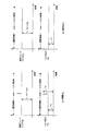
まず、第1の従来技術の構成について図4を用いて説明する。図4は、第1従来例のモータ制御装置の構成を示す図である。図4において、1aはモータ制御装置、2はモータ、6はモータ2の速度を検出する速度検出器、11は電流制御部、41は速度制御ゲイン、42は積分制御部、43は暴走防止部、44は積分演算制御部、45は−1の積分制御係数である。
本モータ制御装置1aは、電流制御部11、速度制御ゲイン41、積分制御部42、暴走防止部43、積分演算制御部44、積分制御係数45で構成されており、速度制限指令Vlm、速度検出器6の出力である速度フィードバックVfb、外部トルク指令Trfを入力し、速度制限中は速度制限指令Vlmが速度フィードバックVfbに一致するようにモータ2を駆動し、トルク制御中はモータ2のトルクが外部トルク指令Trfに一致するようにモータ2を駆動する。
速度制限指令Vlmと速度フィードバックVfbとを入力として時定数Tで積分を行なう積分制御部42と速度制御ゲイン41とで速度制御を形成しており、内部トルク指令Traを生成する。速度誤差は速度制限指令Vlmと速度フィードバックVfbとの差である。暴走防止部43は、内部トルク指令Traと外部トルク指令Trfとを切り換えて、電流制御部11へ出力している。電流制御部11の出力信号によりモータ5を駆動する。
First, the configuration of the first prior art will be described with reference to FIG. FIG. 4 is a diagram showing the configuration of the motor control device of the first conventional example. In FIG. 4, 1a is a motor control device, 2 is a motor, 6 is a speed detector for detecting the speed of the
The motor control device 1a includes a
The speed control is formed by the
次に動作について図5のフローチャートで説明する。図5は、第1従来例のモータ制御装置の動作を示すフローチャートである。
まず、ステップT01で速度制限指令Vlmと速度フィードバックVfbとの差である速度誤差εを作る。
次に、ステップT02で速度制限中かトルク制御中かを判定する。これは、暴走防止部43の出力信号が外部トルク指令Trfならばトルク制御中となる。ここで、図4において、積分演算制御部44は、トルク制御中ならばaが選択され、速度制限中ならばbが選択される。ステップT02で速度制限中と判定された場合は、積分演算制御部44はbが選択され、ステップT04に進む。一方、ステップ02でトルク制御中と判定された場合は、積分演算制御部44はaが選択され、ステップT03に進む。
ステップT04では、積分演算制御部44において、aが選択されていると積分制御部42により時定数Tで積分制御され、bが選択されていると積分制御係数45により積分制御部42の出力の逆極性が入力されることになり、積分制御部42の出力は時定数Tで減少していく。
次に、ステップT05で積分制御部42の出力と速度誤差εの加算値が速度制御ゲイン41の入力となる、
次にステップT06で速度制御ゲイン41を乗じて内部トルク指令Traを作成する。
次に、ステップT07ないしステップT10で、暴走防止部43において、内部トルク指令Traと外部トルク指令Trfとの比較を行ない、電流制御部11への指令を選択する。外部トルク指令Trfが電流制御部11への指令となる条件は、外部トルク指令Trfと内部トルク指令Traの方向が同一でかつ外部トルク指令Trfが内部トルク指令Traよりも小さい場合である。それ以外のときは、内部トルク指令Traが電流制御部11への指令となる。
次に、ステップT11で、暴走防止部43の出力により電流制御部11がモータ5を駆動し、ステップT12で、速度検出器6により速度フィードバックVfbを作成する。
Next, the operation will be described with reference to the flowchart of FIG. FIG. 5 is a flowchart showing the operation of the motor controller of the first conventional example.
First, in step T01, a speed error ε, which is the difference between the speed limit command Vlm and the speed feedback Vfb, is created.
Next, in step T02, it is determined whether speed is being limited or torque is being controlled. If the output signal of the
In step T04, when a is selected in the integration
Next, in step T05, the output value of the
Next, in step T06, the internal torque command Tra is created by multiplying the
Next, in steps T07 to T10, the
Next, in step T11, the
以上のように、速度制限中とトルク制御中とで積分演算制御方法を切り換えており、速度制限中は積分制御部の出力を大きくし、トルク制御中は積分制御部の出力を小さくすることで、2つの状態を交互に繰り返すことにより、速度制限指令に対する定常偏差を補正し、また、速度制限指令を超えないように電流制御部への指令を与え、速度制限機能付きトルク制御を実現しているのである。 As described above, the integral calculation control method is switched between speed limiting and torque control. The output of the integral control unit is increased during speed limitation, and the output of the integral control unit is decreased during torque control. By repeating the two states alternately, the steady deviation with respect to the speed limit command is corrected, and a command to the current control unit is given so as not to exceed the speed limit command, thereby realizing torque control with a speed limit function. It is.
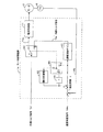
次に、第2の従来技術について図6を用いて説明する。図6は、第2従来例のモータ制御装置の構成を示す図である。図6において、1bはモータ制御装置、12aは速度演算部、71はトルク電流補正部、72は最大トルク制御部、73ベクトル演算部、74は印加電圧作成部、75は補正演算部である。
第2の従来技術では、モータ出力トルクを制御するトルク指令型モータ制御装置において、モータの回転速度限界を超えないように回転速度を制限するモータ制御構成を提供しており、主に、外部トルク電流指令Irfを補正しトルク電流指令Irを算出するトルク電流補正部71と、磁極位置センサからの位置信号U,V,Wを用いてモータ回転速度Vmを算出する速度演算部12aと、トルク電流指令Irに基づいて励磁電流指令Iexを算出する最大トルク制御部72と、モータ定数とトルク電流指令Ir及び励磁電流指令Iexとモータ回転速度Vm等から電圧指令を演算するベクトル演算部73と、U,V,W相の印加電圧を作成する印加電圧作成部74と、ベクトル演算部73や印加電圧作成部74等への各種補正演算を行なう補正演算部75とで構成されている。トルク電流補正部71は、モータ回転速度Vmが所定の速度制限指令Vlmを超えないように、主にPI制御を用いて外部トルク電流指令Irfを補正し、トルク電流指令Irを算出している。トルク電流補正部71では、モータ回転速度Vmが速度制限指令Vlmを下回っている場合は、トルク電流補正値はゼロとなり、外部トルク電流指令Irfとトルク電流指令Irは同じ値になる。すなわち、モータ回転速度Vmが速度制限指令Vlmを超えた場合にトルク電流指令Irの補正を行なっている。
Next, the second prior art will be described with reference to FIG. FIG. 6 is a diagram showing the configuration of the motor control device of the second conventional example. In FIG. 6, 1b is a motor control device, 12a is a speed calculation unit, 71 is a torque current correction unit, 72 is a maximum torque control unit, 73 vector calculation unit, 74 is an applied voltage generation unit, and 75 is a correction calculation unit.
The second prior art provides a motor control configuration for limiting the rotational speed so as not to exceed the rotational speed limit of the motor in the torque command type motor control device for controlling the motor output torque. A torque current correction unit 71 that corrects the current command Irf and calculates the torque current command Ir; a
しかしながら、第1の従来技術は、電流制御部への指令を選択する暴走防止部において、外部トルク指令と内部トルク指令の方向が異なる場合(例えば、一方向へ進み過ぎたので反対方向へ動作させる場合等)には内部トルク指令が選択されているので、外部トルク指令の方向を反転し反対方向の動作をさせようとしても、外部トルク指令で動作しないため、反対方向の動作ができないという問題があった。
また、第1の従来技術も第2の従来技術も、モータの回転速度限界を超えないように回転速度を制限するトルク指令型モータ制御装置であって、位置制御や速度制御からトルク制御モードへのダイレクトな制御モード切り換え動作については記載されておらず、このような制御モード切り換えを行うことができないという問題があった。
However, according to the first conventional technique, in the runaway prevention unit that selects a command to the current control unit, when the direction of the external torque command and the internal torque command are different (for example, the motor has advanced in one direction, so the operation is performed in the opposite direction. In other cases, the internal torque command is selected, so even if the direction of the external torque command is reversed and the operation in the opposite direction is attempted, the operation in the opposite direction cannot be performed because the operation is not performed with the external torque command. there were.
Both the first and second prior arts are torque command type motor control devices that limit the rotational speed so as not to exceed the rotational speed limit of the motor, from position control and speed control to torque control mode. This direct control mode switching operation is not described, and there is a problem that such control mode switching cannot be performed.
本発明はこのような問題点に鑑みてなされたものであり、外部トルク指令の方向を反転した場合でも、反対方向の動作が可能であり、また、位置制御モードや速度制御モードからトルク制御モードへ制御モードを切り換える際において、モータ動作の連続性を保つことができるモータ制御装置およびそのトルク制御方法を提供することを目的とする。 The present invention has been made in view of such problems, and even when the direction of the external torque command is reversed, operation in the opposite direction is possible, and the torque control mode can be changed from the position control mode or the speed control mode. An object of the present invention is to provide a motor control device and its torque control method that can maintain the continuity of motor operation when switching the control mode.
上記問題を解決するため、本発明は、次のように構成したのである。
請求項1に記載の発明は、速度指令(Vrf)にモータ(2)の速度フィードバック(Vfb)が一致するようにPI(比例積分)制御演算を行い内部トルク指令(Tra)を算出する速度制御部(10)と、外部から指令される制御切換信号(Cmd)に基づいて前記速度指令(Vrf)に前記速度フィードバック(Vfb)が一致するように速度制御を行う速度制御モードと外部トルク指令(Trf)にモータの発生トルクが一致するようにトルク制御を行うトルク制御モードとの制御モード切り換えを行い切換信号(Sm)を出力する制御切換部(13)と、前記切換信号(Sm)に基づいて前記内部トルク指令(Tra)と前記外部トルク指令(Trf)とを切り換えてトルク指令(Trb)を出力するトルク指令切換器(14)と、前記トルク指令(Trb)に基づいて前記モータ(2)を駆動する電流制御部(11)を備えたモータ制御装置において、速度制御モードからトルク制御モードへの切換時に、前記制御切換部(13)は、前記外部トルク指令(Trf)と前記速度制御部(10)の積分器(103)の値(Tri)とに基づいて初期値(Tin)を算出し、速度制限指令(Vlm)と前記速度フィードバック(Vfb)と前記初期値(Tin)とに基づいて前記外部トルク指令(Trf)を補正するトルク補正値(Trc)を算出する補正トルク演算部(15)を備えることを特徴とするものである。
In order to solve the above problem, the present invention is configured as follows.
In the first aspect of the invention, the speed control (PI) control calculation is performed so that the speed feedback (Vfb) of the motor (2) matches the speed command (Vrf) to calculate the internal torque command (Tra). A speed control mode for performing speed control and an external torque command (Vfb) so that the speed feedback (Vfb) coincides with the speed command (Vrf) based on a control switching signal (Cmd) commanded from an external unit (10). Based on the switching signal (Sm), a control switching unit (13) for switching a control mode to a torque control mode for performing torque control so that the torque generated by the motor matches Trf) and outputting a switching signal (Sm). A torque command switch (14) for switching between the internal torque command (Tra) and the external torque command (Trf) to output a torque command (Trb), and based on the torque command (Trb). Accordingly, in the motor control device including the current control unit (11) for driving the motor (2), when switching from the speed control mode to the torque control mode, the control switching unit (13) The initial value (Tin) is calculated based on Trf) and the value (Tri) of the integrator (103) of the speed controller (10), and the speed limit command (Vlm), the speed feedback (Vfb), and the initial value are calculated. A correction torque calculation unit (15) for calculating a torque correction value (Trc) for correcting the external torque command (Trf) based on the value (Tin) is provided.
また、請求項2に記載の発明は、速度指令(Vrf)にモータ(2)の速度フィードバック(Vfb)が一致するようにPI(比例積分)制御演算を行い内部トルク指令(Tra)を算出する速度制御部(10)と、外部から指令される制御切換信号(Cmd)に基づいて位置指令に位置フィードバックが一致するように位置制御を行う位置制御モードと外部トルク指令(Trf)にモータの発生トルクが一致するようにトルク制御を行うトルク制御モードとの制御モード切り換えを行い切換信号(Sm)を出力する制御切換部(13)と、前記切換信号(Sm)に基づいて前記内部トルク指令(Tra)と前記外部トルク指令(Trf)とを切り換えてトルク指令(Trb)を出力するトルク指令切換器(14)と、前記トルク指令(Trb)に基づいて前記モータ(2)を駆動する電流制御部(11)を備えたモータ制御装置において、位置制御モードからトルク制御モードへの切換時に、前記制御切換部(13)は、前記外部トルク指令(Trf)と前記速度制御部(10)の積分器(103)の値(Tri)とに基づいて初期値(Tin)を算出し、速度制限指令(Vlm)と前記速度フィードバック(Vfb)と前記初期値(Tin)とに基づいて前記外部トルク指令(Trf)を補正するトルク補正値(Trc)を算出する補正トルク演算部(15)を備えることを特徴とするものである。 The invention according to claim 2 calculates the internal torque command (Tra) by performing PI (proportional integration) control calculation so that the speed feedback (Vfb) of the motor (2) matches the speed command (Vrf). Generation of a motor in a position control mode for performing position control and an external torque command (Trf) so that position feedback matches the position command based on a speed control unit (10) and a control switching signal (Cmd) commanded from outside A control switching unit (13) that outputs a switching signal (Sm) by switching a control mode to a torque control mode that performs torque control so that the torques coincide with each other, and the internal torque command (Sm) based on the switching signal (Sm). A torque command switch (14) for switching between Tra) and the external torque command (Trf) and outputting a torque command (Trb), and the motor based on the torque command (Trb) 2) In the motor control device including the current control unit (11) for driving 2), when switching from the position control mode to the torque control mode, the control switching unit (13) includes the external torque command (Trf) and the speed. An initial value (Tin) is calculated based on the value (Tri) of the integrator (103) of the control unit (10), and a speed limit command (Vlm), the speed feedback (Vfb), and the initial value (Tin) And a correction torque calculator (15) for calculating a torque correction value (Trc) for correcting the external torque command (Trf) based on the above.
また、請求項3に記載の発明は、請求項1または2に記載のモータ制御装置において、前記制御切換部(13)は、前記積分器(103)の値(Tri)に代えて、前記内部トルク指令(Tra)に基づいて初期値(Tin)を算出することを特徴とするものである。 According to a third aspect of the present invention, in the motor control device according to the first or second aspect, the control switching unit (13) replaces the value (Tri) of the integrator (103) with the internal control unit (13). The initial value (Tin) is calculated based on the torque command (Tra).
また、請求項4に記載の発明は、請求項1または2に記載のモータ制御装置において、補正トルク演算部(15)は、比例ゲイン(161)と積分ゲイン(162)と積分器(163)とで構成し、前記速度フィードバック(Vfb)から前記速度制限指令(Vlm)を差引いた偏差に前記比例ゲイン(161)の値を乗じた値と、前記偏差に前記積分ゲイン(162)の値を乗じた値を前記積分器(163)で前記初期値(Tin)を初期値として積分した値とを加算した余剰トルク(Tov)を算出する余剰トルク演算部(16)と、前記余剰トルク(Tov)と前記速度フィードバック(Vfb)とに基づいて前記積分器(163)をクリアするクリア信号(Cl)と補正切換信号(Sc)とを発生するトルク補正判定部17と、前記補正切換信号(Sc)に基づいて前記余剰トルク(Tov)とゼロとを切り換えて前記トルク補正値(Trc)を出力するスイッチ(18)とを備えることを特徴とするものである。
According to a fourth aspect of the present invention, in the motor control device according to the first or second aspect, the correction torque calculation unit (15) includes a proportional gain (161), an integral gain (162), and an integrator (163). The deviation obtained by subtracting the speed limit command (Vlm) from the speed feedback (Vfb) is multiplied by the value of the proportional gain (161), and the deviation is multiplied by the value of the integral gain (162). A surplus torque calculation unit (16) for calculating a surplus torque (Tov) obtained by adding a value obtained by multiplying the multiplied value by the integrator (163) using the initial value (Tin) as an initial value, and the surplus torque (Tov) ) And the speed feedback (Vfb), a torque
また、請求項5に記載の発明は、請求項4に記載のモータ制御装置において、前記トルク補正判定部(17)は、前記余剰トルク(Tov)の符号と前記速度フィードバック(Vfb)の符号とが異なる場合に、前記クリア信号(Cl)を発生し、前記スイッチ(18)がゼロを出力するように前記補正切換信号(Sc)を発生することを特徴とするものである。 According to a fifth aspect of the present invention, in the motor control device according to the fourth aspect, the torque correction determination unit (17) includes a sign of the surplus torque (Tov) and a sign of the speed feedback (Vfb). Are different from each other, the clear signal (Cl) is generated, and the correction switching signal (Sc) is generated so that the switch (18) outputs zero.
また、請求項6に記載の発明は、速度指令(Vrf)にモータ(2)の速度フィードバック(Vfb)が一致するようにPI(比例積分)制御演算を行い内部トルク指令(Tra)を算出する速度制御部(10)と、外部から指令される制御切換信号(Cmd)に基づいて前記速度指令(Vrf)に前記速度フィードバック(Vfb)が一致するように速度制御を行う速度制御モードと外部トルク指令(Trf)にモータの発生トルクが一致するようにトルク制御を行うトルク制御モードとの制御モード切り換えを行い切換信号(Sm)を出力する制御切換部(13)と、前記切換信号(Sm)に基づいて前記内部トルク指令(Tra)と前記外部トルク指令(Trf)とを切り換えてトルク指令(Trb)を出力するトルク指令切換器(14)と、前記トルク指令(Trb)に基づいて前記モータ(2)を駆動する電流制御部(11)を備えたモータ制御装置のトルク制御方法において、速度制御モードからトルク制御モードへの切換時に、前記外部トルク指令(Trf)と前記速度制御部(10)の積分器(103)の値(Tri)とに基づいて初期値(Tin)を算出するステップと、速度制限指令(Vlm)と前記速度フィードバック(Vfb)と前記初期値(Tin)とに基づいて前記外部トルク指令(Trf)を補正するトルク補正値(Trc)を算出するステップとを備えることを特徴とするものである。 According to the sixth aspect of the present invention, PI (proportional integration) control calculation is performed to calculate the internal torque command (Tra) so that the speed feedback (Vfb) of the motor (2) matches the speed command (Vrf). A speed control mode and an external torque for controlling the speed so that the speed feedback (Vfb) matches the speed command (Vrf) based on a speed control unit (10) and a control switching signal (Cmd) commanded from the outside. A control switching unit (13) for switching a control mode to a torque control mode for performing torque control so that the torque generated by the motor matches the command (Trf) and outputting a switching signal (Sm); and the switching signal (Sm) A torque command switch (14) for switching between the internal torque command (Tra) and the external torque command (Trf) based on the output, and outputting a torque command (Trb), and the torque command (Trb) ) Based on the external torque command (Trf) at the time of switching from the speed control mode to the torque control mode in the torque control method of the motor control device including the current control unit (11) for driving the motor (2) based on A step of calculating an initial value (Tin) based on the value (Tri) of the integrator (103) of the speed control unit (10), a speed limit command (Vlm), the speed feedback (Vfb), and the initial value; And calculating a torque correction value (Trc) for correcting the external torque command (Trf) based on (Tin).
また、請求項7に記載の発明は、速度指令(Vrf)にモータ(2)の速度フィードバック(Vfb)が一致するようにPI(比例積分)制御演算を行い内部トルク指令(Tra)を算出する速度制御部(10)と、外部から指令される制御切換信号(Cmd)に基づいて位置指令に位置フィードバックが一致するように位置制御を行う位置制御モードと外部トルク指令(Trf)にモータの発生トルクが一致するようにトルク制御を行うトルク制御モードとの制御モード切り換えを行い切換信号(Sm)を出力する制御切換部(13)と、前記切換信号(Sm)に基づいて前記内部トルク指令(Tra)と前記外部トルク指令(Trf)とを切り換えてトルク指令(Trb)を出力するトルク指令切換器(14)と、前記トルク指令(Trb)に基づいて前記モータ(2)を駆動する電流制御部(11)を備えたモータ制御装置のトルク制御方法において、位置制御モードからトルク制御モードへの切換時に、前記外部トルク指令(Trf)と前記速度制御部(10)の積分器(103)の値(Tri)とに基づいて初期値(Tin)を算出するステップと、速度制限指令(Vlm)と前記速度フィードバック(Vfb)と前記初期値(Tin)とに基づいて前記外部トルク指令(Trf)を補正するトルク補正値(Trc)を算出するステップとを備えることを特徴とするものである。 According to the seventh aspect of the invention, an internal torque command (Tra) is calculated by performing PI (proportional integration) control calculation so that the speed feedback (Vfb) of the motor (2) matches the speed command (Vrf). Generation of a motor in a position control mode for performing position control and an external torque command (Trf) so that position feedback matches the position command based on a speed control unit (10) and a control switching signal (Cmd) commanded from outside A control switching unit (13) that outputs a switching signal (Sm) by switching a control mode to a torque control mode that performs torque control so that the torques coincide with each other, and the internal torque command (Sm) based on the switching signal (Sm). A torque command switch (14) for switching between Tra) and the external torque command (Trf) and outputting a torque command (Trb), and the motor based on the torque command (Trb) 2) In the torque control method of the motor control device including the current control unit (11) for driving the external torque command (Trf) and the speed control unit (10) when switching from the position control mode to the torque control mode. The initial value (Tin) is calculated based on the value (Tri) of the integrator (103), and the speed limit command (Vlm), the speed feedback (Vfb), and the initial value (Tin). And a step of calculating a torque correction value (Trc) for correcting the external torque command (Trf).
また、請求項8に記載の発明は、請求項6または7に記載のモータ制御装置のトルク制御方法において、前記初期値(Tin)は、前記積分器(103)の値(Tri)に代えて、前記内部トルク指令(Tra)に基づいて算出することを特徴とするものである。 According to an eighth aspect of the present invention, in the torque control method for a motor control apparatus according to the sixth or seventh aspect, the initial value (Tin) is replaced with a value (Tri) of the integrator (103). The calculation is based on the internal torque command (Tra).
また、請求項9に記載の発明は、請求項6または7に記載のモータ制御装置のトルク制御方法において、前記速度フィードバック(Vfb)から前記速度制限指令(Vlm)を差引いた偏差に比例ゲイン(161)の値を乗じた値と、前記偏差に積分ゲイン(162)の値を乗じた値を積分器(163)で前記初期値(Tin)を初期値として積分した値とを加算して余剰トルク(Tov)を算出し、前記余剰トルク(Tov)と前記速度フィードバック(Vfb)とに基づいて前記積分器(163)をクリアするクリア信号(Cl)と補正切換信号(Sc)とを発生し、前記補正切換信号(Sc)に基づいて前記トルク補正値(Trc)を前記余剰トルク(Tov)またはゼロに切り換えることを特徴とするものである。 The invention according to claim 9 is the torque control method for a motor control device according to claim 6 or 7, wherein a proportional gain () is obtained by subtracting the speed limit command (Vlm) from the speed feedback (Vfb). 161) and a value obtained by multiplying the value obtained by multiplying the deviation by the value of the integral gain (162) with the integrator (163) using the initial value (Tin) as an initial value, and adding a surplus A torque (Tov) is calculated, and a clear signal (Cl) and a correction switching signal (Sc) are generated to clear the integrator (163) based on the surplus torque (Tov) and the speed feedback (Vfb). The torque correction value (Trc) is switched to the surplus torque (Tov) or zero based on the correction switching signal (Sc).
また、請求項10に記載の発明は、請求項9に記載のモータ制御装置のトルク制御方法において、前記余剰トルク(Tov)の符号と前記速度フィードバック(Vfb)の符号とが異なる場合に、前記クリア信号(Cl)を発生し前記トルク補正値(Trc)をゼロとし、前記余剰トルク(Tov)の符号と前記速度フィードバック(Vfb)の符号とが同じ場合には、前記クリア信号(Cl)は発生せず前記トルク補正値(Trc)を前記余剰トルク(Tov)とすることを特徴とするものである。 Further, in the torque control method of the motor control device according to claim 9, when the sign of the surplus torque (Tov) and the sign of the speed feedback (Vfb) are different, When the clear signal (Cl) is generated, the torque correction value (Trc) is set to zero, and the sign of the surplus torque (Tov) and the sign of the speed feedback (Vfb) are the same, the clear signal (Cl) is The torque correction value (Trc) is not generated, and the surplus torque (Tov) is used.
請求項1に記載の発明によると、外部トルク指令の方向を反転した場合でも、反対方向の動作が可能であり、また、速度制御モードからトルク制御モードへ制御モードを切り換える際において、モータ動作の連続性を保つことができるモータ制御装置を提供することができる。
請求項2に記載の発明によると、外部トルク指令の方向を反転した場合でも、反対方向の動作が可能であり、また、位置制御モードからトルク制御モードへ制御モードを切り換える際において、モータ動作の連続性を保つことができるモータ制御装置を提供することができる。
請求項3ないし5に記載の発明によると、外部トルク指令の方向を反転した場合でも、反対方向の動作が可能であり、また、位置制御モードや速度制御モードからトルク制御モードへ制御モードを切り換える際において、モータ動作の連続性を保つことができるモータ制御装置を提供することができる。
請求項6に記載の発明によると、外部トルク指令の方向を反転した場合でも、反対方向の動作が可能であり、また、速度制御モードからトルク制御モードへ制御モードを切り換える際において、モータ動作の連続性を保つことができるモータ制御装置のトルク制御方法を提供することができる。
請求項7に記載の発明によると、外部トルク指令の方向を反転した場合でも、反対方向の動作が可能であり、また、位置制御モードからトルク制御モードへ制御モードを切り換える際において、モータ動作の連続性を保つことができるモータ制御装置のトルク制御方法を提供することができる。
請求項8ないし10に記載の発明によると、外部トルク指令の方向を反転した場合でも、反対方向の動作が可能であり、また、位置制御モードや速度制御モードからトルク制御モードへ制御モードを切り換える際において、モータ動作の連続性を保つことができるモータ制御装置のトルク制御方法を提供することができる。
According to the first aspect of the present invention, even when the direction of the external torque command is reversed, the operation in the opposite direction is possible, and when the control mode is switched from the speed control mode to the torque control mode, A motor control device that can maintain continuity can be provided.
According to the second aspect of the present invention, even when the direction of the external torque command is reversed, the operation in the opposite direction is possible, and when the control mode is switched from the position control mode to the torque control mode, the motor operation can be performed. A motor control device that can maintain continuity can be provided.
According to the third to fifth aspects of the present invention, even when the direction of the external torque command is reversed, the operation in the opposite direction is possible, and the control mode is switched from the position control mode or the speed control mode to the torque control mode. In this case, it is possible to provide a motor control device that can maintain continuity of motor operation.
According to the invention described in claim 6, even when the direction of the external torque command is reversed, the operation in the opposite direction is possible, and when the control mode is switched from the speed control mode to the torque control mode, A torque control method for a motor control device that can maintain continuity can be provided.
According to the seventh aspect of the present invention, even when the direction of the external torque command is reversed, the operation in the opposite direction is possible, and when the control mode is switched from the position control mode to the torque control mode, the motor operation can be performed. A torque control method for a motor control device that can maintain continuity can be provided.
According to the invention described in claims 8 to 10, even when the direction of the external torque command is reversed, the operation in the opposite direction is possible, and the control mode is switched from the position control mode or the speed control mode to the torque control mode. In this case, it is possible to provide a torque control method for a motor control device that can maintain continuity of motor operation.
以下、本発明の実施の形態について図を参照して説明する。
また、実際のモータ制御装置には様々な機能や手段が内蔵されているが、図には本発明に関係する機能や手段のみを記載し説明することとする。また、以下同一名称には極力同一符号を付け重複説明を省略する。
Hereinafter, embodiments of the present invention will be described with reference to the drawings.
Further, although various functions and means are built in the actual motor control device, only the functions and means related to the present invention will be described and described in the figure. Hereinafter, the same reference numerals are assigned to the same names as much as possible, and the duplicate description is omitted.
図1は、本発明の第1実施例のモータ制御装置の構成を示す図である。図1において、1はモータ制御装置、3はモータ2の位置を検出する位置検出器、10は速度制御部、12は速度演算部、13制御切換部、14はトルク指令切換器、15は補正トルク演算部、16は余剰トルク演算部、17はトルク補正判定部、18スイッチである。また、101および161は比例ゲイン、102および162は積分ゲイン、103および163は積分器である。
FIG. 1 is a diagram illustrating a configuration of a motor control device according to a first embodiment of the present invention. In FIG. 1, 1 is a motor control device, 3 is a position detector for detecting the position of the
モータ制御装置1は、速度制御部10と電流制御部11と速度演算部12と制御切換部13とトルク指令切換器14と補正トルク演算部15とで構成されている。
速度制御部10は、比例ゲイン101と積分ゲイン102と積分器103とで構成されており、速度指令Vrfから速度演算部12で得られた速度フィードバックVfbを差引いた偏差ε1に比例ゲイン101の値Kv1を乗じた値と、偏差ε1に積分ゲイン102の値Ki1を乗じた値を積分器103で積分した値Triとを加算したものを、内部トルク指令Traとしてトルク指令切換器14へ出力する。
電流制御部11は、トルク指令切換器14で選択されたトルク指令Trbに基づいてモータ2を駆動するものであり、図示していないが、トルク指令Trbに応じたモータ電流を制御するための電流制御ループを構成しており、電力変換部(図示せず)を含めたものとしている。
速度演算部12は、位置検出器3のモータ位置検出信号から速度フィードバックVfbを演算するものである。
The
The
The
The speed calculation unit 12 calculates speed feedback Vfb from the motor position detection signal of the position detector 3.
制御切換部13は、制御切換信号Cmd、速度制御部10の積分器103の値Tri、および外部トルク指令Trfを入力し、トルク指令切換器14へ切換信号Smを出力すると共に、前記制御切換信号Cmdがトルク制御モードのときは、トルク制御モードへの切り換え時に外部トルク指令Trfから速度制御部10の積分器103の値Triを差引いた値Tinを余剰トルク演算部16の積分器163へ初期値として与えるものである。
補正トルク演算部15は、余剰トルク演算部16とトルク補正判定部17とスイッチ18とで構成され、速度制限指令Vlmと速度フィードバックVfbと初期値Tinとに基づいて外部トルク指令Trfを補正するトルク補正値Trcを算出する。
トルク指令切換器14は、制御切換部13からの切換信号Smに基づいて、速度制御部10からの内部トルク指令Traと外部トルク指令Trfからスイッチ18の出力であるトルク補正値Trcを差引いたトルク指令とを切り換えるスイッチである。切換信号Smがトルク制御モードのときは、14bを選択し、それ以外のときは、14aを選択する。
The
The correction torque calculation unit 15 includes a surplus torque calculation unit 16, a torque
Based on the switching signal Sm from the
余剰トルク演算部16は、比例ゲイン161と積分ゲイン162と積分器163とで構成されており、速度フィードバックVfbから速度制限指令Vlmを差引いた偏差ε2に比例ゲイン161の値Kv2を乗じた値と、偏差ε2に積分ゲイン162の値Ki2を乗じた値を積分器163で制御切換部13より受取った初期値Tinを初期値として積分した値とを加算したものを、余剰トルクTovとしてトルク補正判定部17およびスイッチ18へ出力する。
トルク補正判定部17は、余剰トルク演算部16で得られた余剰トルクTovの符号と速度フィードバックVfbの符号を比較して、異なっている場合は、積分器163をクリアするクリア信号Clと補正切換信号Scとを発生して、積分器163をクリアすると共にスイッチ18をゼロ(18b)に切り換える。
また、余剰トルクTovの符号と速度フィードバックVfbの符号が同じであれば、積分器163をクリアするクリア信号Clは発生せず、スイッチ18を18aに切り換える。
The surplus torque calculation unit 16 includes a
The torque
If the sign of the surplus torque Tov and the sign of the speed feedback Vfb are the same, the clear signal Cl for clearing the
本発明が特許文献1と異なる点は、補正トルク演算部と制御切換部を備え、外部トルク指令に補正を実施している点である。
特許文献1の発明は、一方向におけるトルク制御での速度制限動作が可能であるが、反転動作や速度制御からトルク制御への切り換え動作を行なうことができない。本発明によれば、補正トルク演算部と速度制御部と制御切換部を備えているので、トルク制御での反転動作や速度制御からトルク制御への切り換え動作を連続的に行なうことができるという効果がある。
また、特許文献2と異なる点は、特許文献2のトルク電流補正部が、本発明の補正トルク演算部の機能に類似しているが、速度制御部と制御切換部は備えていない。
特許文献2の発明は、トルク制御での速度制限動作が可能であるが、速度制御からトルク制御への切り換え動作を行なうことができない。本発明によれば、速度制御部と制御切換部を備えているので、速度制御からトルク制御への切り換え動作を連続的に行なうことができるという効果がある。
The present invention is different from
The invention of
Further, the difference from Patent Document 2 is that the torque current correction unit of Patent Document 2 is similar in function to the correction torque calculation unit of the present invention, but does not include a speed control unit and a control switching unit.
The invention of Patent Document 2 can perform a speed limiting operation in torque control, but cannot perform a switching operation from speed control to torque control. According to the present invention, since the speed control unit and the control switching unit are provided, there is an effect that the switching operation from the speed control to the torque control can be continuously performed.
次に、動作について説明する。
まず、速度制御モードからトルク制御モードへ切り換えるときの動作について説明する。
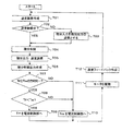
速度制御モードからトルク制御モードへの切り換え動作の手順として図2のフローチャートで説明する。
まず、ステップS01で制御切換信号がトルク制御モードへ切り換わると、ステップS02で制御切換部13がトルク指令切換器14を接点14bに接続すると共に、外部トルク指令Trfから速度制御部10の積分器103の値Triを差引いた値Tinを余剰トルク演算部16の積分器163の初期値として与える。
Tin=Trf−Tri (1)
次にステップS03で速度演算部12によって速度フィードバックVfbを求める。
次に、ステップS04で余剰トルク演算部16によって余剰トルクTovを求める。余剰トルクTovは、速度フィードバックVfbから速度制限指令Vlmを差引いた値に比例ゲイン161の値Kv2乗じた比例項と速度フィードバックVfbから速度制限指令Vlmを差引いた値に積分ゲイン162の値Ki2を乗じた値を積分器163で積分した積分項の和として求めるが、積分器163には、ステップS02で初期値Tinが与えられている。
Tov=(Vfb−Vlm)×Kv2+{Tin+(Vfb−Vlm)×Ki2×t} (2)
ただし、tは制御切換信号がトルク制御モードへ切り換わってからの時間
次に、ステップS05で余剰トルクTovの補正を実施するか否かを判定する。判定は、トルク補正判定部17によって余剰トルクTovと速度フィードバックVfbの正負の符号を比較し、同じ符号であれば補正を実施する。
Next, the operation will be described.
First, the operation when switching from the speed control mode to the torque control mode will be described.
The procedure for switching from the speed control mode to the torque control mode will be described with reference to the flowchart of FIG.
First, when the control switching signal is switched to the torque control mode in step S01, the
Tin = Trf−Tri (1)
Next, in step S03, the speed calculator 12 obtains the speed feedback Vfb.
Next, the surplus torque Tov is obtained by the surplus torque calculator 16 in step S04. The surplus torque Tov is obtained by multiplying the value obtained by subtracting the speed limit command Vlm from the speed feedback Vfb and the value Kv2 of the
Tov = (Vfb−Vlm) × Kv2 + {Tin + (Vfb−Vlm) × Ki2 × t} (2)
However, t is the time from when the control switching signal is switched to the torque control mode. Next, in step S05, it is determined whether or not to correct the surplus torque Tov. In the determination, the torque
次に、ステップS05で補正を実施するように判定された場合は、ステップS06でスイッチ18を接点18aに接続する。
一方、ステップS05で補正を実施しないように判定された場合は、ステップS07でスイッチ18を出力値がゼロとなる接点18bに接続し、ステップS08で余剰トルク演算部16の積分器163の値をクリアする。
次に、ステップS09で外部トルク指令Trfからスイッチ18の出力値を引いたトルク指令をトルク指令切換器14の接点14bに入力する。
最後に、ステップS10でトルク指令切換器14から出力されたトルク指令Trbに基づいて電流制御部11によってモータ2を駆動する。以後、トルク制御モードではステップS03からステップS10を繰り返す。
Next, when it is determined in step S05 that correction is to be performed, the
On the other hand, if it is determined not to perform correction in step S05, the
Next, in step S09, the torque command obtained by subtracting the output value of the
Finally, the motor 2 is driven by the
ここで、補正を実施する場合のトルク制御モードへの制御切り換え動作の連続性について説明する。
トルク制御モードへ切り換える前は速度制御部がPI制御を実施しているので、速度指令Vrfと速度フィードバックVfbはほぼ一致しており、
Vrf≒Vfb
なので、
Vrf−Vfb≒0
となり、比例ゲイン101の出力は、ほぼ0となっている。
また、速度制御部10の積分器103には、加減速トルクや負荷(外乱)トルクが溜まっている。よって、制御切り換え直前に速度制御部10から出力されている内部トルク指令Traは、積分器103の値Triにほぼ等しい。
Tra≒Tri
Here, the continuity of the control switching operation to the torque control mode when the correction is performed will be described.
Before switching to the torque control mode, the speed control unit performs the PI control, so the speed command Vrf and the speed feedback Vfb are almost the same,
Vrf ≒ Vfb
So,
Vrf−Vfb ≒ 0
Thus, the output of the
The
Tra ≒ Tri
次に、制御切り換え後に電流制御部11へ入力されるトルク指令Trbは、トルク指令切換器14は接点14bが選択され、スイッチ18は接点18aが選択されるので、
Trb=Trf−Tov
であるが、式(1)および式(2)より余剰トルクTovは、
Tov={(Trf−Tri)+(Vfb−Vlm)×(Kv2+Ki2×t)}
となる。したがって、
Trb=Trf−{(Trf−Tri)+(Vfb−Vlm)×(Kv2+Ki2×t)} (3)
ここで、Tri=Traを(3)式に代入すると、(4)が得られる。
Trb=Tra+(Vfb−Vlm)×(Kv2+Ki2×t)} (4)
(4)式よりにおいて、
t=0
とすると、制御切り換え直後のトルク指令Trbが求められ、
Trb=Tra+(Vfb−Vlm)×Kv2
となり、電流制御部11のトルク指令Trbは、切り換え直前のトルク指令Traを基準とするトルク指令を出力するため、モータ動作の連続性を保つことができる。
Next, the torque command Trb input to the
Trb = Trf−Tov
However, from the equations (1) and (2), the surplus torque Tov is
Tov = {(Trf−Tri) + (Vfb−Vlm) × (Kv2 + Ki2 × t)}
It becomes. Therefore,
Trb = Trf − {(Trf−Tri) + (Vfb−Vlm) × (Kv2 + Ki2 × t)} (3)
Here, when Tri = Tra is substituted into the equation (3), (4) is obtained.
Trb = Tra + (Vfb−Vlm) × (Kv2 + Ki2 × t)} (4)
From equation (4),
t = 0
Then, the torque command Trb immediately after the control switching is obtained,
Trb = Tra + (Vfb−Vlm) × Kv2
Thus, since the torque command Trb of the
図3は、本発明の第1実施例のモータ制御装置において速度制御モードからトルク制御モードへ切り換えたときのトルク指令Trbと速度フィードバックVfbの挙動の一例を示す図である。(a)はトルク補償がない場合であり、(b)は本発明のトルク補償を行った場合である。
図3は、速度制御モードでは、速度指令Vrfで動作しており、速度フィードバックVfb=Vrfである。トルク指令Trbは、負荷(外乱)トルクである一定の内部トルク指令Traを出力し、トルク指令Trb=Traとなっている。
この状態から、外部トルク指令Trfが内部トルク指令Traよりも大きく(Trf>Tra)、速度制限指令Vlmが速度指令Vrfと等しい(Vlm=Vrf)条件のトルク制御モードへ切り換える。
FIG. 3 is a diagram showing an example of the behavior of the torque command Trb and the speed feedback Vfb when the speed control mode is switched to the torque control mode in the motor control apparatus of the first embodiment of the present invention. (A) is a case where there is no torque compensation, (b) is a case where the torque compensation of this invention is performed.
FIG. 3 shows that in the speed control mode, operation is performed with a speed command Vrf, and speed feedback Vfb = Vrf. The torque command Trb outputs a constant internal torque command Tra, which is a load (disturbance) torque, and the torque command Trb = Tra.
From this state, the torque control mode is switched to a condition where the external torque command Trf is larger than the internal torque command Tra (Trf> Tra) and the speed limit command Vlm is equal to the speed command Vrf (Vlm = Vrf).
(a)の場合、切り換え時は、余剰トルク演算部16の積分器163の積分値はゼロであり、速度制限指令Vlmと速度フィードバックVfbは等しいため、トルク指令Trbは外部トルク指令Trfが出力され、その結果、速度フィードバックVfbは、速度制限指令Vlmを超過していく。その後、速度制限指令に対する速度フィードバックの超過に対してPI制御し、求められた余剰トルクが外部トルク指令から差引かれ、最終的に、トルク指令Trbは切り換え前の内部トルク指令Traに収束し、速度フィードバックVfbは速度制限指令Vlmに収束する。
In the case of (a), at the time of switching, the integral value of the
一方、(b)の場合、切り換え時は、余剰トルク演算部16の積分器163に初期値が設定されており、速度制限指令Vlmが速度フィードバックVfbと等しいため、トルク指令Trbは切り換え前の内部トルク指令Traと等しくなる。その結果、速度フィードバックVfbも切り換え前の速度と変化なく動作することができ、以後、トルク指令Trbは切り換え前の内部トルク指令Traを出力し続け、速度フィードバックVfbは切り換え前の速度を維持し続ける。
On the other hand, in the case of (b), at the time of switching, the initial value is set in the
本実施例では、トルク制御モードへの切り換え時に外部トルク指令Trfから速度制御部10の積分器103の値Triを差引いた値Tinを余剰トルク演算部16の積分器163への初期値として与えたが、速度制御部10の積分器103の値Triの代わりに速度制御部10の出力である内部トルク指令Traを用いても良い。
In this embodiment, a value Tin obtained by subtracting the value Tri of the
以上、速度制御モードからトルク制御モードへの切り換え動作について、説明した。
つぎに、位置制御モードからトルク制御モードへの切り換え動作について、説明する。
図1では、速度指令を外部システムからの速度指令Vrfとしているが、モータ制御装置1内に位置指令と位置フィードバックを入力とする位置制御部を備えて、位置制御部から出力される信号を速度指令Vrfとしても良い。
速度制御と位置制御の差は、速度制御部10へ入力される速度指令Vrfの出所の違いだけであるため、速度制御モードからトルク制御モードへの切り換え動作と位置制御モードからトルク制御モードへの切り換え動作は、図1において同じとなる。
このように、本発明のトルク制御方法は、位置制御においても、速度制御モードからトルク制御モードへ切り換える方法と同様にして、位置制御モードからトルク制御モードへ切り換えることが可能である。
The switching operation from the speed control mode to the torque control mode has been described above.
Next, the switching operation from the position control mode to the torque control mode will be described.
In FIG. 1, the speed command is the speed command Vrf from the external system. However, the
Since the difference between the speed control and the position control is only the difference in the origin of the speed command Vrf input to the
As described above, the torque control method of the present invention can be switched from the position control mode to the torque control mode in the position control as well as the method of switching from the speed control mode to the torque control mode.
以上のように、トルク制御モードへの制御切り換えにおいて、外部トルク指令Trfと速度制御部10の積分値Triとの差を余剰トルク演算部16の積分器の初期値として与えているため、切り換え直後のトルク指令Trbを切り換え時点での内部トルク指令Traを基準とした値とすることができ、連続的なモータ動作を実現できる。すなわち、モータの実運転中に連続的な制御モード切り換えができるといえる。また、外部トルク指令の方向を反転した場合にも、反対方向の動作ができる。
As described above, in the control switching to the torque control mode, the difference between the external torque command Trf and the integral value Tri of the
本発明のモータ制御装置は、モータの実運転中に制御モードをトルク制御モードへダイレクトに切り換えられるので、NC等のモーションコントロールシステムにおいて産業上幅広く利用可能である。例えば、工作機械などへの適用には有効である。 Since the motor control device of the present invention can be switched directly to the torque control mode during actual operation of the motor, it can be widely used industrially in motion control systems such as NC. For example, it is effective for application to machine tools.
1、1a、1b モータ制御装置
2 モータ
3 位置検出器
6 速度検出器
10 速度制御部
11 電流制御部
12、12a 速度演算部
13 制御切換部
14 トルク指令切換器
15 補正トルク演算部
16 余剰トルク演算部
17 トルク補正判定部
18 スイッチ
41 速度制御ゲイン
42 積分制御部
43 暴走防止部
44 積分演算制御部
45 積分制御係数
71 トルク電流補正部
72 最大トルク制御部
73 ベクトル演算部
74 印加電圧作成部
75 補正演算部
101、161 比例ゲイン
102、162 積分ゲイン
103、163 積分器
DESCRIPTION OF
Claims (10)
外部から指令される制御切換信号(Cmd)に基づいて前記速度指令(Vrf)に前記速度フィードバック(Vfb)が一致するように速度制御を行う速度制御モードと外部トルク指令(Trf)にモータの発生トルクが一致するようにトルク制御を行うトルク制御モードとの制御モード切り換えを行い切換信号(Sm)を出力する制御切換部(13)と、
前記切換信号(Sm)に基づいて前記内部トルク指令(Tra)と前記外部トルク指令(Trf)とを切り換えてトルク指令(Trb)を出力するトルク指令切換器(14)と、
前記トルク指令(Trb)に基づいて前記モータ(2)を駆動する電流制御部(11)とを備えたモータ制御装置において、
トルク制御モードの時に前記外部トルク指令(Trf)を補正するトルク補正値(Trc)を算出する補正トルク演算部(15)を備え、
前記制御切換部(13)は、速度制御モードからトルク制御モードへの切り換え時に前記外部トルク指令(Trf)と前記速度制御部(10)の積分器(103)の値(Tri)とに基づいて初期値(Tin)を算出し、
前記補正トルク演算部(15)は、速度制限指令(Vlm)と前記速度フィードバック(Vfb)と前記初期値(Tin)とに基づいて前記トルク補正値(Trc)を算出することを特徴とするモータ制御装置。 A speed control unit (10) that performs PI (proportional integral) control calculation so as to match the speed feedback (Vfb) of the motor (2) with the speed command (Vrf) and calculates an internal torque command (Tra);
Generation of a motor in a speed control mode in which speed control is performed so that the speed feedback (Vfb) matches the speed command (Vrf) based on a control switching signal (Cmd) commanded from the outside, and an external torque command (Trf) A control switching unit (13) for switching a control mode to a torque control mode for performing torque control so that the torques coincide with each other and outputting a switching signal (Sm);
A torque command switch (14) for switching the internal torque command (Tra) and the external torque command (Trf) based on the switching signal (Sm) and outputting the torque command (Trb);
In a motor control device including a current control unit (11) that drives the motor (2) based on the torque command (Trb),
A correction torque calculator (15) for calculating a torque correction value (Trc) for correcting the external torque command (Trf) in the torque control mode;
The control switching unit (13) is based on the external torque command (Trf) and the value (Tri) of the integrator (103) of the speed control unit (10) when switching from the speed control mode to the torque control mode. Calculate the initial value (Tin)
The correction torque calculator (15) calculates the torque correction value (Trc) based on a speed limit command (Vlm), the speed feedback (Vfb), and the initial value (Tin). Control device.
外部から指令される制御切換信号(Cmd)に基づいて位置指令に位置フィードバックが一致するように位置制御を行う位置制御モードと外部トルク指令(Trf)にモータの発生トルクが一致するようにトルク制御を行うトルク制御モードとの制御モード切り換えを行い切換信号(Sm)を出力する制御切換部(13)と、
前記切換信号(Sm)に基づいて前記内部トルク指令(Tra)と前記外部トルク指令(Trf)とを切り換えてトルク指令(Trb)を出力するトルク指令切換器(14)と、
前記トルク指令(Trb)に基づいて前記モータ(2)を駆動する電流制御部(11)とを備えたモータ制御装置において、
トルク制御モードの時に前記外部トルク指令(Trf)を補正するトルク補正値(Trc)を算出する補正トルク演算部(15)を備え、
前記制御切換部(13)は、位置制御モードからトルク制御モードへの切り換え時に前記外部トルク指令(Trf)と前記速度制御部(10)の積分器(103)の値(Tri)とに基づいて初期値(Tin)を算出し、
前記補正トルク演算部(15)は、速度制限指令(Vlm)と前記速度フィードバック(Vfb)と前記初期値(Tin)とに基づいて前記トルク補正値(Trc)を算出することを特徴とするモータ制御装置。 A speed control unit (10) that performs PI (proportional integral) control calculation so as to match the speed feedback (Vfb) of the motor (2) with the speed command (Vrf) and calculates an internal torque command (Tra);
Based on a control switching signal (Cmd) commanded from the outside, torque control is performed so that the generated torque of the motor matches the position control mode for performing position control so that the position feedback matches the position command and the external torque command (Trf). A control switching unit (13) for switching the control mode to the torque control mode for performing and outputting a switching signal (Sm);
A torque command switch (14) for switching the internal torque command (Tra) and the external torque command (Trf) based on the switching signal (Sm) and outputting the torque command (Trb);
In a motor control device including a current control unit (11) that drives the motor (2) based on the torque command (Trb),
A correction torque calculator (15) for calculating a torque correction value (Trc) for correcting the external torque command (Trf) in the torque control mode;
The control switching unit (13) is based on the external torque command (Trf) and the value (Tri) of the integrator (103) of the speed control unit (10) when switching from the position control mode to the torque control mode. Calculate the initial value (Tin)
The correction torque calculator (15) calculates the torque correction value (Trc) based on a speed limit command (Vlm), the speed feedback (Vfb), and the initial value (Tin). Control device.
前記余剰トルク(Tov)と前記速度フィードバック(Vfb)とに基づいて前記積分器(163)をクリアするクリア信号(Cl)と補正切換信号(Sc)とを発生するトルク補正判定部(17)と、
前記補正切換信号(Sc)に基づいて前記余剰トルク(Tov)とゼロとを切り換えて前記トルク補正値(Trc)を出力するスイッチ(18)とを備えることを特徴とする請求項1または2に記載のモータ制御装置。 The correction torque calculation unit (15) includes a proportional gain (161), an integral gain (162), and an integrator (163), and the deviation is obtained by subtracting the speed limit command (Vlm) from the speed feedback (Vfb). A value obtained by multiplying the value obtained by multiplying the value of the proportional gain (161) and the value obtained by multiplying the deviation by the value of the integral gain (162) by the integrator (163) using the initial value (Tin) as an initial value. A surplus torque calculator (16) for calculating the added surplus torque (Tov);
A torque correction determination unit (17) for generating a clear signal (Cl) and a correction switching signal (Sc) for clearing the integrator (163) based on the surplus torque (Tov) and the speed feedback (Vfb); ,
3. A switch (18) for switching the surplus torque (Tov) and zero based on the correction switching signal (Sc) and outputting the torque correction value (Trc). The motor control apparatus described.
外部から指令される制御切換信号(Cmd)に基づいて前記速度指令(Vrf)に前記速度フィードバック(Vfb)が一致するように速度制御を行う速度制御モードと外部トルク指令(Trf)にモータの発生トルクが一致するようにトルク制御を行うトルク制御モードとの制御モード切り換えを行い切換信号(Sm)を出力する制御切換部(13)と、
前記切換信号(Sm)に基づいて前記内部トルク指令(Tra)と前記外部トルク指令(Trf)とを切り換えてトルク指令(Trb)を出力するトルク指令切換器(14)と、
前記トルク指令(Trb)に基づいて前記モータ(2)を駆動する電流制御部(11)とを備えたモータ制御装置のトルク制御方法において、
速度制御モードからトルク制御モードへの切り換え時に、前記外部トルク指令(Trf)と前記速度制御部(10)の積分器(103)の値(Tri)とに基づいて初期値(Tin)を算出するステップと、
速度制限指令(Vlm)と前記速度フィードバック(Vfb)と前記初期値(Tin)とに基づいて前記外部トルク指令(Trf)を補正するトルク補正値(Trc)を算出するステップとを備えることを特徴とするモータ制御装置のトルク制御方法。 A speed control unit (10) that performs PI (proportional integral) control calculation so as to match the speed feedback (Vfb) of the motor (2) with the speed command (Vrf) and calculates an internal torque command (Tra);
Generation of a motor in a speed control mode in which speed control is performed so that the speed feedback (Vfb) matches the speed command (Vrf) based on a control switching signal (Cmd) commanded from the outside, and an external torque command (Trf) A control switching unit (13) for switching a control mode to a torque control mode for performing torque control so that the torques coincide with each other and outputting a switching signal (Sm);
A torque command switch (14) for switching the internal torque command (Tra) and the external torque command (Trf) based on the switching signal (Sm) and outputting the torque command (Trb);
In a torque control method of a motor control device comprising a current control unit (11) for driving the motor (2) based on the torque command (Trb),
At the time of switching from the speed control mode to the torque control mode, an initial value (Tin) is calculated based on the external torque command (Trf) and the value (Tri) of the integrator (103) of the speed control unit (10). Steps,
Calculating a torque correction value (Trc) for correcting the external torque command (Trf) based on the speed limit command (Vlm), the speed feedback (Vfb), and the initial value (Tin). A torque control method for the motor control device.
外部から指令される制御切換信号(Cmd)に基づいて位置指令に位置フィードバックが一致するように位置制御を行う位置制御モードと外部トルク指令(Trf)にモータの発生トルクが一致するようにトルク制御を行うトルク制御モードとの制御モード切り換えを行い切換信号(Sm)を出力する制御切換部(13)と、
前記切換信号(Sm)に基づいて前記内部トルク指令(Tra)と前記外部トルク指令(Trf)とを切り換えてトルク指令(Trb)を出力するトルク指令切換器(14)と、
前記トルク指令(Trb)に基づいて前記モータ(2)を駆動する電流制御部(11)とを備えたモータ制御装置のトルク制御方法において、
位置制御モードからトルク制御モードへの切り換え時に、前記外部トルク指令(Trf)と前記速度制御部(10)の積分器(103)の値(Tri)とに基づいて初期値(Tin)を算出するステップと、
速度制限指令(Vlm)と前記速度フィードバック(Vfb)と前記初期値(Tin)とに基づいて前記外部トルク指令(Trf)を補正するトルク補正値(Trc)を算出するステップとを備えることを特徴とするモータ制御装置のトルク制御方法。 A speed control unit (10) that performs PI (proportional integral) control calculation so as to match the speed feedback (Vfb) of the motor (2) with the speed command (Vrf) and calculates an internal torque command (Tra);
Based on a control switching signal (Cmd) commanded from the outside, torque control is performed so that the generated torque of the motor matches the position control mode for performing position control so that the position feedback matches the position command and the external torque command (Trf). A control switching unit (13) for switching the control mode to the torque control mode for performing and outputting a switching signal (Sm);
A torque command switch (14) for switching the internal torque command (Tra) and the external torque command (Trf) based on the switching signal (Sm) and outputting the torque command (Trb);
In a torque control method of a motor control device comprising a current control unit (11) for driving the motor (2) based on the torque command (Trb),
At the time of switching from the position control mode to the torque control mode, an initial value (Tin) is calculated based on the external torque command (Trf) and the value (Tri) of the integrator (103) of the speed control unit (10). Steps,
Calculating a torque correction value (Trc) for correcting the external torque command (Trf) based on the speed limit command (Vlm), the speed feedback (Vfb), and the initial value (Tin). A torque control method for the motor control device.
前記余剰トルク(Tov)と前記速度フィードバック(Vfb)とに基づいて前記積分器(163)をクリアするクリア信号(Cl)と補正切換信号(Sc)とを発生し、
前記補正切換信号(Sc)に基づいて前記トルク補正値(Trc)を前記余剰トルク(Tov)またはゼロに切り換えることを特徴とする請求項6または7に記載のモータ制御装置のトルク制御方法。 An integrator (the value obtained by multiplying the deviation obtained by subtracting the speed limit command (Vlm) from the speed feedback (Vfb) by the value of the proportional gain (161) and the value obtained by multiplying the deviation by the value of the integral gain (162). 163) and adding the value integrated with the initial value (Tin) as the initial value to calculate the surplus torque (Tov),
Generating a clear signal (Cl) and a correction switching signal (Sc) for clearing the integrator (163) based on the surplus torque (Tov) and the speed feedback (Vfb);
The torque control method for a motor control device according to claim 6 or 7, wherein the torque correction value (Trc) is switched to the surplus torque (Tov) or zero based on the correction switching signal (Sc).
Priority Applications (1)
| Application Number | Priority Date | Filing Date | Title |
|---|---|---|---|
| JP2007312227A JP2009141987A (en) | 2007-12-03 | 2007-12-03 | Motor controller and method of controlling torque thereof |
Applications Claiming Priority (1)
| Application Number | Priority Date | Filing Date | Title |
|---|---|---|---|
| JP2007312227A JP2009141987A (en) | 2007-12-03 | 2007-12-03 | Motor controller and method of controlling torque thereof |
Publications (1)
| Publication Number | Publication Date |
|---|---|
| JP2009141987A true JP2009141987A (en) | 2009-06-25 |
Family
ID=40872064
Family Applications (1)
| Application Number | Title | Priority Date | Filing Date |
|---|---|---|---|
| JP2007312227A Pending JP2009141987A (en) | 2007-12-03 | 2007-12-03 | Motor controller and method of controlling torque thereof |
Country Status (1)
| Country | Link |
|---|---|
| JP (1) | JP2009141987A (en) |
Cited By (6)
| Publication number | Priority date | Publication date | Assignee | Title |
|---|---|---|---|---|
| WO2011145366A1 (en) * | 2010-05-17 | 2011-11-24 | 三菱電機株式会社 | Motor control device |
| KR101563270B1 (en) | 2014-05-29 | 2015-10-26 | 알에스오토메이션주식회사 | Control device and control method for the same |
| CN105610383A (en) * | 2014-11-13 | 2016-05-25 | 东芝机械株式会社 | Electric machine and display method |
| US9853585B2 (en) | 2015-06-02 | 2017-12-26 | Kabushiki Kaisha Yaskawa Denki | Motor control apparatus, motor control method and motor control program |
| CN107894749A (en) * | 2016-10-04 | 2018-04-10 | 发那科株式会社 | Servo motor control unit and its method, computer-readable recording medium |
| CN112764394A (en) * | 2020-12-29 | 2021-05-07 | 上海维宏电子科技股份有限公司 | Method, equipment, device, processor and storage medium for realizing speed-limiting control for workpiece machining track in numerical control system |
-
2007
- 2007-12-03 JP JP2007312227A patent/JP2009141987A/en active Pending
Cited By (15)
| Publication number | Priority date | Publication date | Assignee | Title |
|---|---|---|---|---|
| DE112011101670B4 (en) | 2010-05-17 | 2018-09-13 | Mitsubishi Electric Corporation | motor controller |
| DE112011101670T5 (en) | 2010-05-17 | 2013-05-16 | Mitsubishi Electric Corporation | motor controller |
| JP5372249B2 (en) * | 2010-05-17 | 2013-12-18 | 三菱電機株式会社 | Motor control device |
| KR101354221B1 (en) | 2010-05-17 | 2014-01-22 | 미쓰비시덴키 가부시키가이샤 | Motor control device |
| US8928267B2 (en) | 2010-05-17 | 2015-01-06 | Mitsubishi Electric Corporation | Motor controller |
| WO2011145366A1 (en) * | 2010-05-17 | 2011-11-24 | 三菱電機株式会社 | Motor control device |
| DE112011101670B9 (en) * | 2010-05-17 | 2018-11-15 | Mitsubishi Electric Corporation | motor controller |
| KR101563270B1 (en) | 2014-05-29 | 2015-10-26 | 알에스오토메이션주식회사 | Control device and control method for the same |
| CN105610383A (en) * | 2014-11-13 | 2016-05-25 | 东芝机械株式会社 | Electric machine and display method |
| CN105610383B (en) * | 2014-11-13 | 2018-09-11 | 东芝机械株式会社 | Motor machine and display methods |
| US9853585B2 (en) | 2015-06-02 | 2017-12-26 | Kabushiki Kaisha Yaskawa Denki | Motor control apparatus, motor control method and motor control program |
| CN107894749A (en) * | 2016-10-04 | 2018-04-10 | 发那科株式会社 | Servo motor control unit and its method, computer-readable recording medium |
| CN107894749B (en) * | 2016-10-04 | 2020-08-04 | 发那科株式会社 | Servo motor control device, servo motor control method, and computer-readable recording medium |
| CN112764394A (en) * | 2020-12-29 | 2021-05-07 | 上海维宏电子科技股份有限公司 | Method, equipment, device, processor and storage medium for realizing speed-limiting control for workpiece machining track in numerical control system |
| CN112764394B (en) * | 2020-12-29 | 2022-05-03 | 上海维宏电子科技股份有限公司 | Method, device and apparatus for controlling machining trajectory of workpiece, processor and medium thereof |
Similar Documents
| Publication | Publication Date | Title |
|---|---|---|
| JP6519695B2 (en) | Electric power steering device | |
| US10494017B2 (en) | Electric power steering apparatus | |
| US7126304B2 (en) | Motor controller and electric power steering apparatus | |
| JP2018108816A (en) | Electric power steering device | |
| JP2009141987A (en) | Motor controller and method of controlling torque thereof | |
| KR100798222B1 (en) | Electric power steering control apparatus | |
| JP2016172459A (en) | Steering device | |
| US9317028B2 (en) | Electric motor control device | |
| EP1863163B1 (en) | Motor controller | |
| US20080149414A1 (en) | Vehicular steering apparatus | |
| JP2006298002A (en) | Electric power steering control device | |
| JPH1127951A (en) | Pwm inverter controller | |
| JP2006217746A (en) | Motor controller | |
| US8082080B2 (en) | Electric power steering apparatus | |
| JP5293136B2 (en) | Vehicle steering system | |
| JP2007143276A (en) | Rotor angle estimating method and controller of dc brushless motor | |
| JP2006018431A (en) | Servo control device | |
| JP2001051722A (en) | Controller | |
| JP2007210354A (en) | Steering device for vehicle | |
| JP2005088709A (en) | Steering device | |
| JP2020090168A (en) | Electric power steering device | |
| JP2008056079A (en) | Motor control device | |
| JP2007253670A (en) | Control device for electric power steering device | |
| JP2010020705A (en) | Control device | |
| KR100764217B1 (en) | Motor output control apparatus in eps system |