JP2009139028A - Control device and control method for control device - Google Patents
Control device and control method for control device Download PDFInfo
- Publication number
- JP2009139028A JP2009139028A JP2007316596A JP2007316596A JP2009139028A JP 2009139028 A JP2009139028 A JP 2009139028A JP 2007316596 A JP2007316596 A JP 2007316596A JP 2007316596 A JP2007316596 A JP 2007316596A JP 2009139028 A JP2009139028 A JP 2009139028A
- Authority
- JP
- Japan
- Prior art keywords
- defrosting operation
- output
- refrigerator
- showcase
- showcases
- Prior art date
- Legal status (The legal status is an assumption and is not a legal conclusion. Google has not performed a legal analysis and makes no representation as to the accuracy of the status listed.)
- Pending
Links
Images


Classifications
-
- F—MECHANICAL ENGINEERING; LIGHTING; HEATING; WEAPONS; BLASTING
- F25—REFRIGERATION OR COOLING; COMBINED HEATING AND REFRIGERATION SYSTEMS; HEAT PUMP SYSTEMS; MANUFACTURE OR STORAGE OF ICE; LIQUEFACTION SOLIDIFICATION OF GASES
- F25D—REFRIGERATORS; COLD ROOMS; ICE-BOXES; COOLING OR FREEZING APPARATUS NOT OTHERWISE PROVIDED FOR
- F25D21/00—Defrosting; Preventing frosting; Removing condensed or defrost water
- F25D21/002—Defroster control
- F25D21/006—Defroster control with electronic control circuits
-
- F—MECHANICAL ENGINEERING; LIGHTING; HEATING; WEAPONS; BLASTING
- F25—REFRIGERATION OR COOLING; COMBINED HEATING AND REFRIGERATION SYSTEMS; HEAT PUMP SYSTEMS; MANUFACTURE OR STORAGE OF ICE; LIQUEFACTION SOLIDIFICATION OF GASES
- F25B—REFRIGERATION MACHINES, PLANTS OR SYSTEMS; COMBINED HEATING AND REFRIGERATION SYSTEMS; HEAT PUMP SYSTEMS
- F25B2600/00—Control issues
- F25B2600/02—Compressor control
- F25B2600/021—Inverters therefor
-
- Y—GENERAL TAGGING OF NEW TECHNOLOGICAL DEVELOPMENTS; GENERAL TAGGING OF CROSS-SECTIONAL TECHNOLOGIES SPANNING OVER SEVERAL SECTIONS OF THE IPC; TECHNICAL SUBJECTS COVERED BY FORMER USPC CROSS-REFERENCE ART COLLECTIONS [XRACs] AND DIGESTS
- Y02—TECHNOLOGIES OR APPLICATIONS FOR MITIGATION OR ADAPTATION AGAINST CLIMATE CHANGE
- Y02B—CLIMATE CHANGE MITIGATION TECHNOLOGIES RELATED TO BUILDINGS, e.g. HOUSING, HOUSE APPLIANCES OR RELATED END-USER APPLICATIONS
- Y02B30/00—Energy efficient heating, ventilation or air conditioning [HVAC]
- Y02B30/70—Efficient control or regulation technologies, e.g. for control of refrigerant flow, motor or heating
Abstract
Description
本発明は、制御装置および制御装置の制御方法に関する。 The present invention relates to a control device and a control method of the control device.
特許文献1には、複数のショーケースおよび冷凍機を有し、これら複数のショーケースおよび冷凍機を制御するコントローラを備える冷凍システムに関する技術が開示されている。
ところで、前述の冷凍システムにおいて、ショーケースの熱交換器に付着した霜を除去する運転である除霜運転を実行する場合、ショーケースへの冷媒の循環を停止して熱交換器の温度を上昇させて除霜を行った後、ショーケースの温度を設定温度まで冷却する動作が実行される。このような除霜運転を行う場合には、冷媒の循環量が急に変化するため、冷凍機の負荷が急激に変動してしまい、システムの運転効率が低下してしまうという問題点がある。 By the way, in the refrigeration system described above, when performing a defrosting operation, which is an operation for removing frost attached to the heat exchanger of the showcase, the circulation of the refrigerant to the showcase is stopped and the temperature of the heat exchanger is increased. Then, after defrosting, the operation of cooling the temperature of the showcase to the set temperature is executed. When such a defrosting operation is performed, since the circulation amount of the refrigerant changes abruptly, the load of the refrigerator is rapidly changed, and there is a problem that the operation efficiency of the system is lowered.
本発明は、上述した事情に鑑みてなされたものであり、冷凍システムの除霜運転を効率良く実行することが可能な制御装置および制御装置の制御方法に関する。 The present invention has been made in view of the above-described circumstances, and relates to a control device and a control method for the control device that can efficiently perform a defrosting operation of a refrigeration system.
上記目的を達成するために、本発明は、冷凍機と、前記冷凍機と冷媒管により接続された複数のショーケースとを備えた冷凍システムを制御する制御装置において、所定の前記ショーケースから除霜運転を行う旨の通知を受けた場合、または、記憶部に記憶されている各ショーケースの除霜運転開始時刻を示す情報と現在時刻とに基づいて所定の前記ショーケースが除霜運転を行うことを検出した場合には、前記除霜運転を開始する際に前記冷凍機の出力を定常状態よりも低下させる制御を行うとともに、前記除霜運転を終了する際に前記冷凍機の出力を定常状態よりも上昇させる制御を行う制御手段を備えることを特徴とする。
この構成によれば、除霜運転を開始する際に冷凍機の出力を低下させ、除霜運転を終了する際に冷凍機の出力を上昇させる。これにより、冷凍システムの除霜運転を効率良く実行することが可能となる。
In order to achieve the above object, the present invention provides a control device for controlling a refrigeration system comprising a refrigerator and a plurality of showcases connected to the refrigerator and refrigerant pipes, by removing from the predetermined showcase. When the notification that the frost operation is performed is received, or based on the information indicating the defrost operation start time of each showcase stored in the storage unit and the current time, the predetermined showcase performs the defrost operation. When it is detected that the defrosting operation is started, the output of the refrigerator is controlled to be lower than the steady state when the defrosting operation is started, and the output of the refrigerator is reduced when the defrosting operation is finished. It is characterized by comprising a control means for performing control to raise from the steady state.
According to this configuration, the output of the refrigerator is reduced when the defrosting operation is started, and the output of the refrigerator is increased when the defrosting operation is finished. Thereby, it is possible to efficiently perform the defrosting operation of the refrigeration system.
また、本発明は、上記発明において、前記制御手段は、除霜運転を終了する際に前記冷凍機の出力を上昇させた後、前記除霜運転を行った前記ショーケースの庫内温度が設定温度付近に復元した場合には、前記冷凍機の出力を定常状態まで低下させる制御を行うことを特徴とする。
この構成によれば、除霜運転の終了の際に冷凍機の出力を上昇させた後、ショーケースの庫内温度が設定温度付近に復元した場合には、冷凍機の出力を定常状態まで低下させる。これにより、除霜運転が終了し、ショーケースの庫内温度が設定温度に近づいた場合には、冷凍機の出力を定常状態に迅速に復元させることで、電力消費を抑えることができる。
Further, the present invention is the above invention, wherein the control means sets an internal temperature of the showcase that has performed the defrosting operation after increasing the output of the refrigerator when the defrosting operation is finished. When the temperature is restored near the temperature, control is performed to reduce the output of the refrigerator to a steady state.
According to this configuration, after increasing the output of the refrigerator at the end of the defrosting operation, the output of the refrigerator is reduced to a steady state when the inside temperature of the showcase is restored near the set temperature. Let Thereby, when the defrosting operation is completed and the inside temperature of the showcase approaches the set temperature, the power consumption can be suppressed by quickly restoring the output of the refrigerator to a steady state.
また、本発明は、上記発明において、前記制御手段は、前記除霜運転開始後における前記冷凍機の出力の低下量を予め測定して記憶し、記憶されている当該低下量に基づいて、除霜運転を開始する際の前記冷凍機の出力を低下させることを特徴とする。
この構成によれば、除霜運転を開始する際の冷凍機の出力を記憶値に基づいて低下させる。このため、記憶されている実測値に基づいて制御を行うことから、最適な制御により電力消費を抑えることができる。
Further, according to the present invention, in the above invention, the control unit measures and stores in advance a reduction amount of the output of the refrigerator after the start of the defrosting operation, and removes the control unit based on the stored reduction amount. The output of the refrigerator when starting the frost operation is reduced.
According to this configuration, the output of the refrigerator when starting the defrosting operation is reduced based on the stored value. For this reason, since control is performed based on the stored actual measurement value, power consumption can be suppressed by optimal control.
また、本発明は、上記発明において、複数のショーケースが同期して前記除霜運転を開始し、前記制御手段は、前記複数のショーケースのうち、前記除霜運転を終了するショーケースの台数に応じて、前記冷凍機の出力を上昇させることを特徴とする。
この構成によれば、同期して除霜運転を行う複数のショーケースのうち、除霜運転を終了するショーケースの台数に応じて、冷凍機の出力を上昇させる。このため、除霜運転の所要時間がショーケース毎に異なる場合であっても、出力を段階的に上昇させることにより、最適な制御を行い、電力消費を抑えることができる。
Further, the present invention is the above invention, wherein a plurality of showcases synchronously start the defrosting operation, and the control means is the number of showcases that end the defrosting operation among the plurality of showcases. According to the above, the output of the refrigerator is increased.
According to this structure, the output of a refrigerator is raised according to the number of the showcases which complete | finish a defrost operation among the some showcases which perform a defrost operation synchronously. For this reason, even if the time required for the defrosting operation differs for each showcase, it is possible to perform optimal control and suppress power consumption by increasing the output stepwise.
また、本発明は、冷凍機と、前記冷凍機と冷媒管により接続された複数のショーケースとを備えた冷凍システムを制御する制御装置の制御方法において、所定の前記ショーケースから除霜運転を行う旨の通知を受けた場合、または、記憶部に記憶されている各ショーケースの除霜運転開始時刻を示す情報と現在時刻とに基づいて所定の前記ショーケースが除霜運転を行うことを検出した場合には、前記除霜運転を開始する際に前記冷凍機の出力を低下させる制御を行うとともに、前記除霜運転を終了する際に前記冷凍機の出力を上昇させる制御を行う、ことを特徴とする。
この構成によれば、除霜運転を開始する際に冷凍機の出力を低下させ、除霜運転を終了する際に冷凍機の出力を上昇させる。これにより、冷凍システムの除霜運転を効率良く実行することが可能となる。
Further, the present invention provides a control method for a control device that controls a refrigeration system including a refrigerator and a plurality of showcases connected to the refrigerator by refrigerant pipes, and performs a defrosting operation from the predetermined showcase. When a notification to the effect is received, or the predetermined showcase performs the defrosting operation based on the information indicating the defrosting operation start time of each showcase stored in the storage unit and the current time. If detected, control is performed to reduce the output of the refrigerator when starting the defrosting operation, and control is performed to increase the output of the refrigerator when finishing the defrosting operation. It is characterized by.
According to this configuration, the output of the refrigerator is reduced when the defrosting operation is started, and the output of the refrigerator is increased when the defrosting operation is finished. Thereby, it is possible to efficiently perform the defrosting operation of the refrigeration system.
本発明によれば、冷凍システムの除霜運転を効率良く実行することが可能な制御装置および制御装置の制御方法を提供することができる。 ADVANTAGE OF THE INVENTION According to this invention, the control apparatus and the control method of a control apparatus which can perform the defrost operation of a refrigeration system efficiently can be provided.
(A)実施の形態の説明
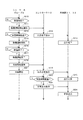
図1は、本発明の実施の形態の構成例を示す図である。図1に示すように、本発明の実施の形態の冷凍システムは、スーパーマーケットまたはコンビニエンスストア等の店舗に配置され、商品の冷凍または冷蔵を行うためのシステムである。冷凍システムは、コントローラ10(請求項中「制御装置」に対応)、ショーケース21〜24(請求項中「ショーケース」に対応)、冷凍機31,32(請求項中「冷凍機」に対応)、冷媒管41,42、および、通信線50を有している。
(A) Description of Embodiment FIG. 1 is a diagram illustrating a configuration example of an embodiment of the present invention. As shown in FIG. 1, the refrigeration system according to the embodiment of the present invention is a system for freezing or refrigeration of merchandise that is arranged in a store such as a supermarket or a convenience store. The refrigeration system corresponds to the controller 10 (corresponding to “control device” in claims), showcases 21 to 24 (corresponding to “showcase” in claims), and
ここで、コントローラ10は、後述するように、例えば、パーソナルコンピュータ等の汎用コンピュータによって構成され、ショーケース21〜24および冷凍機31,32を制御する。ショーケース21〜24は、スーパーマーケットまたはコンビニエンスストアの店舗内に配置され、商品がその庫内に陳列される。また、ショーケース21〜24は、冷媒管41,42に並列に接続され、冷凍機31,32から冷媒管41を介して供給される液相冷媒を取り込んで、後述する冷却装置において蒸発させ、庫内の空気との間で熱交換を行うことにより、庫内の温度を低下させる。そして、冷却装置において気化された気相冷媒は、冷媒管42を介して冷凍機31,32に戻される。また、ショーケース21〜24は、通信線50によってコントローラ10に接続され、コントローラ10との間で情報を授受する。
Here, as will be described later, the
冷凍機31,32は、後述するように圧縮機および熱交換器等を有しており、ショーケース21〜24によって蒸発された気相冷媒を冷媒管42を介して回収し、圧縮機によって圧縮し、凝縮器によって凝縮することにより再び液相冷媒とし、冷媒管41を介してショーケース21〜24に供給する。また、冷凍機31,32は、コントローラ10と通信線50によって接続されており、コントローラ10との間で通信線50を介して情報を授受する。
As will be described later, the
図2は、図1に示すショーケース21〜24および冷凍機31,32の冷媒回路を示す図である。この図に示すように、冷凍機31,32およびショーケース21〜24は、冷媒管41,42に対してそれぞれ並列に接続されている。冷凍機31の冷媒回路としては、アキュムレータ31a、圧縮機31b、凝縮器31c、および、受液器31dを有している。ここで、アキュムレータ31aは、ショーケース21〜24から供給される気相冷媒を気液分離し、気相冷媒のみを圧縮機31bに供給する。圧縮機31bは、不図示のモータによって駆動され、アキュムレータ31aから供給された気相冷媒を圧縮し、高温高圧の冷媒として凝縮器31cに供給する。凝縮器31cは、圧縮機31bから供給された気相冷媒を放熱して凝縮し、液相冷媒として受液器31dに供給する。受液器31dは、凝縮器31cから供給された液相冷媒を一旦貯留した後、冷媒管41を介してショーケース21〜24に供給する。なお、冷凍機32は、冷凍機31と同様の構成であるので、その説明は省略する。
FIG. 2 is a diagram showing the refrigerant circuits of the
ショーケース21は、電磁弁21a、膨張弁21b、および、冷却装置21cを有している。ここで、電磁弁21aは、ショーケース21への液相冷媒の流入をオンまたはオフするための弁である。膨張弁21bは、電磁弁21aを介して供給された液相冷媒を膨張気化させるための弁である。冷却装置21cは、膨張弁21bによって膨張された冷媒が供給され、気化させることにより気化熱を奪う。冷却装置21cは、ショーケース21の庫内の空気との間で熱交換を行うことにより、庫内の温度を設定温度まで低下させる。なお、ショーケース22〜24は、ショーケース21と同様の構成とされているので、その説明は省略する。また、図2の例では、ショーケース21〜24のそれぞれに対して電磁弁21a〜24aをそれぞれ設けるようにしたが、電磁弁を1つだけ設け、その入口側を冷媒管41に接続するとともに、出口側を膨張弁21b〜24bに接続するようにしてもよい。
The
図3は、図1に示すコントローラ10の電気的な構成例を示すブロック図である。図3に示すように、コントローラ10は、CPU(Central Processing Unit)10a(請求項中「制御手段」に対応)、ROM(Read Only Memory)10b、RAM(Random Access Memory)10c、HDD(Hard Disk Drive)10d(請求項中「記憶部」に対応)、画像処理部10e、表示装置10f、バス10g、I/F(Interface)10h、および、入力装置10iを有している。ここで、CPU10aは、ROM10bおよびHDD10dに格納されているプログラムに応じて各種演算処理を実行するとともに、ショーケース21〜24および冷凍機31,32を制御する。ROM10bは、CPU10aが実行する基本的なプログラムを格納している。RAM10cは、CPU10aがプログラムを実行する際のワークエリアとして使用される。HDD10dは、ハードディスクに情報を読み書きする記憶装置であり、図3の例では、プログラム10d1およびデータ10d2を格納している。プログラム10d1は、例えば、OS(Operating System)および後述する処理を実行するための手順を記述したプログラムを有している。データ10d2は、後述する処理において参照される情報を有している。画像処理部10eは、CPU10aから供給された描画命令に基づいて描画処理を実行し、得られた画像を映像信号に変換して表示装置10fに供給する。表示装置10fは、例えば、LCD(Liquid Crystal Display)等によって構成され、画像処理部10eから供給された映像信号を表示部に表示する。バス10gは、CPU10a、ROM10b、RAM10c、HDD10d、画像処理部10e、および、I/F10hを相互に接続し、これらの間で情報の授受を可能とする。I/F10hは、通信線50を介してショーケース21〜24および冷凍機31,32が接続されこれらとの間で情報の授受を行う際のプロトコルの変換等を実行する。また、I/F10hには、入力装置10iが接続され、管理者によって入力装置10iが操作された場合には、入力装置10iから出力される情報をCPU10aに供給する。
FIG. 3 is a block diagram illustrating an electrical configuration example of the
次に本発明の実施の形態の動作について説明する。 Next, the operation of the embodiment of the present invention will be described.
まず、店舗へのコントローラ10、ショーケース21〜24、冷凍機31,32の設置が完了すると、システムの管理者(または設置担当者)は、コントローラ10の入力装置10iを操作し、ショーケース21〜24の庫内温度を、陳列する商品に応じて設定するとともに、ショーケース21〜24の除霜運転に関する設定を行う。具体的には、庫内に陳列する商品の種類(例えば、肉、魚、乳製品等)に応じて、庫内温度の設定を行う。また、除霜運転については、除霜運転を実行する際のグループ分けを設定する。図1の例では、ショーケース21,22が除霜グループAに設定され、ショーケース23,24が除霜グループBに設定されている。このようなグループは、例えば、隣接して配置されるショーケースが同一のグループとなるように設定する。これにより、除霜運転によって暖められた空気が隣接する他のショーケースに流入して庫内の温度が上昇することを防止できる。また、管理者は、コントローラ10の入力装置10iを操作して、それぞれの除霜グループの除霜運転を開始する時刻(以下、「除霜運転開始時刻」と称する)を入力する。その結果、入力された除霜運転開始時刻は、ショーケース21〜24に対して通信線50を介して供給され、ショーケース21〜24のそれぞれの制御部(不図示)が当該除霜運転開始時刻を取得して記憶する。このようにして除霜運転のグループと除霜運転開始時刻が設定されると、各ショーケース21〜24は、図示せぬタイマによって供給される時刻と、記憶されている除霜運転開始時刻とを比較し、これらが一致した場合に、図4に示す処理を実行する。
First, when the installation of the
図4は、除霜グループAにおいて除霜運転が実行される場合におけるショーケース21,22、コントローラ10、および、冷凍機31,32で実行される処理の一例を示す図である。この処理が開始されると、除霜グループAに属するショーケース21,22は、ステップS10において、コントローラ10によって設定された除霜運転開始時刻になったか否かを判定し、除霜運転開始時刻になった場合(ステップS10;Yes)にはステップS11に進み、それ以外の場合(ステップS10;No)には除霜運転開始時刻になるまで同様の処理を繰り返す。ショーケース21,22のタイマは同期しており、また、除霜運転開始時刻は同一グループでは同じであるので、例えば、除霜運転開始時刻になった場合にはステップS10においてYesと判定されてステップS11に進む。
FIG. 4 is a diagram illustrating an example of processing performed in the
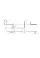
ステップS11では、ショーケース21,22は、コントローラ10に対して通信線50を介して除霜運転開始通知を行う。すなわち、ショーケース21,22の図示せぬ制御部は、通信線50を介してコントローラ10に対して除霜運転を開始する旨の通知を行う。この結果、コントローラ10では、CPU10aがI/F10hを介して除霜運転開始通知を受信する。そして、ステップS12に進み、CPU10aは、I/F10hおよび通信線50を介して冷凍機31,32に対して出力を低下させるように指示をする。より詳細には、CPU10aは、除霜グループAが除霜運転を開始することにより減少する出力に対応する分だけ出力を低下するように冷凍機31,32に指示を行う。具体的には、図5に示すように、除霜運転開始時刻であるT0における冷凍機31,32の出力がP2である場合には、出力をΔPだけ低下させて、P1にするように指示をする。ΔPの具体的にな値については、除霜グループAに実際に除霜運転を実行させ、除霜運転によって減少する出力を測定し、これをΔPとして用いるようにしてもよい。なお、除霜グループBについては、設定温度、機種、および、陳列される商品の量等が異なることから、別途ΔPを求める必要がある。
In step S <b> 11, the
コントローラ10から出力低下指示を受けた冷凍機31,32では、ステップS13において、ΔPだけ出力を低下させる制御を行う。例えば、圧縮機31b,32bを駆動するモータがインバータから供給される電力によって駆動されている場合には、インバータの周波数を低下させることによりモータの回転数を低下させ、出力を低下させる。また、モータがインバータを有しない場合には、例えば、冷凍機31,32の双方またはいずれかを間欠的に停止させることにより、平均的な出力を低下させる。このような制御が実行されることにより、図5に示すように、時刻T1において、冷凍機31,32の出力がΔPだけ低下し、P1となる。
The
このとき、ショーケース21,22では、ステップS14の処理が実行されており、ショーケース21,22は、ステップS11において除霜運転開始通知を行ってから所定の時間が経過しているか否かを判定し、所定の時間が経過している場合(ステップS14;Yes)にはステップS15に進み、それ以外の場合(ステップS14;No)には所定の時間が経過するまで同様の処理を繰り返す。なお、ステップS14における「所定の時間」は、例えば、システムによって異なるので、システム毎に最適値を求めて、当該最適値を「所定の時間」として設定する。なお、最適値を求める方法としては、出力を低下した後、除霜運転を開始した時点における冷凍機31,32の入口温度の上昇が最低となる時間を求める。なお、当該所定の時間を決定する際には、ステップS11において除霜運転開始通知を行ってから出力低下指示が冷凍機31,32に届くまでの通信による遅れ時間も考慮する必要がある。
At this time, in the
ステップS15において除霜運転が開始されると、ショーケース21,22は、膨張弁21b,22bまたは電磁弁21a,22aを閉じ、冷却装置21c,22cへの冷媒の流入を遮断するとともに、冷却装置21c,22cに対してファン(不図示)によって風を送り、冷却装置21c,22cに付着している霜を除く動作を開始する。このようにして、除霜運転が開始されると、ショーケース21,22には冷媒が循環しなくなるので、冷凍機31,32の出力を低下させる必要があるが、本実施の形態では、除霜運転の開始に先行して冷凍機31,32の出力を低下させるようにしたので、不要な冷媒がショーケース21〜24に供給され、冷凍機31,32の出力が無駄に浪費されることを防止できる。
When the defrosting operation is started in step S15, the
ステップS16では、ショーケース21,22は、除霜が終了したか否かを判定し、終了した場合(ステップS16;Yes)にはステップS17に進み、それ以外の場合(ステップS16;No)には除霜が終了するまで同様の処理を繰り返す。より詳細には、ショーケース21,22は、冷却装置21c,22cの温度をセンサによって検出し、当該温度が所定の温度以上になった場合には、除霜が終了したと判定し、ステップS17に進む。なお、ショーケース21,22は、設定温度が異なったり、庫内に陳列されている商品の量(個数)が異なったりするので、除霜の終了はショーケース毎に判断される。
In step S16, the
ステップS17では、除霜が終了したと判定したショーケースは、除霜運転を終了する。つづくステップS18では、除霜が終了したショーケースでは、コントローラ10に対して、除霜が終了し、庫内の温度を設定温度に下げるための冷却運転を開始する旨の通知である冷却開始通知を行う。その結果、コントローラ10では、CPU10aがI/F10hを介してこの冷却開始通知を受信する。CPU10aは、冷却開始通知を受信したことを認識し、ステップS19において、冷凍機31,32に対して出力を上昇させるように指示する出力上昇指示をI/F10hおよび通信線50を介して冷凍機31,32に送る。この結果、冷凍機31,32は、ステップS20において、インバータの周波数を上昇させ、圧縮機31b,32bの回転数を上昇させる。この結果、冷凍機31,32から吐出される液相冷媒の量が増加する。なお、上昇量としては、例えば、冷凍機31,32の出力を最大出力になるように上昇させる。除霜運転によって庫内の温度が上昇しているため、庫内温度を急速に下げる必要があるからである。以上の動作をより詳細に説明すると、図5に示すように、時刻T3において除霜が終了した場合には、時刻T4において冷凍機31,32の出力が最大出力であるP3まで上昇される。
In step S17, the showcase that has determined that the defrosting is finished ends the defrosting operation. In the subsequent step S18, in the showcase in which the defrosting is completed, a cooling start notification that is a notification to the
ステップS21では、除霜が終了したショーケースは、庫内の冷却を開始する。すなわち、除霜が終了したショーケースは、膨張弁または電磁弁を開いた状態とし、冷媒を冷却装置に導く処理を実行する。この結果、除霜が完了したショーケースでは、庫内の再冷却が開始される。 In step S21, the showcase in which the defrosting is finished starts cooling the interior. In other words, the showcase that has been defrosted is in a state in which the expansion valve or the electromagnetic valve is opened, and a process for guiding the refrigerant to the cooling device is executed. As a result, in the showcase in which the defrosting is completed, recooling in the cabinet is started.
ステップS22では、CPU10aは、出力上昇指示を行ってから所定の時間が経過したか否かを判定し、所定の時間が経過した場合(ステップS22;Yes)にはステップS23に進み、それ以外の場合(ステップS22;No)には所定の時間が経過するまで同様の処理を繰り返す。なお、ステップS22における「所定の時間」としては、例えば、冷却を開始してからショーケース21,22の温度が設定温度に戻るまでに必要な時間とすることができる。このような「所定の時間」は、例えば、実測によって求めることができる。
In step S22, the
ステップS23では、CPU10aは、冷凍機31,32に対して、定常出力に戻すように指示を行う。すなわち、CPU10aは、I/F10hおよび通信線50を介して、冷凍機31,32に対して制御信号を送り、冷凍機31,32の出力を定常出力に戻すように指示する。その結果、ステップS24において、冷凍機31,32のインバータの周波数が定常状態の周波数に戻されるので、図5の時刻T5において、冷凍機31,32の出力が定常状態の出力であるP2に戻ることになる。なお、ここで、定常出力とは、冷凍システムが定常常状態における冷凍機31,32の出力をいう。定常状態は、ショーケース21〜24が設置されている環境、庫内に陳列されている商品の種類、個数、および、設定温度等によって変化するので、常に一定しているものではない。そこで、定常状態値としては、例えば、除霜運転を開始する前の状態における出力値を利用することができる。
In step S23, the
なお、以上では、除霜グループAが除霜運転を行う場合を例に挙げて説明したが、除霜グループBが除霜運転を行う場合も、前述の場合と同様の処理が実行される。 In the above description, the case where the defrosting group A performs the defrosting operation has been described as an example. However, even when the defrosting group B performs the defrosting operation, the same process as described above is executed.
以上に説明したように、本発明の実施の形態では、ショーケースが除霜運転を実行する際に、コントローラ10が冷凍機31,32に対して出力を低下させるように指示を行い、冷凍機31,32がこれに応じて出力を低下させるようにした。これにより、除霜運転の実行に先行して、または、略同期して冷凍機31,32の出力を低下することができるので、冷媒が過剰に供給されることを防止し、運転効率を向上させることができる。
As described above, in the embodiment of the present invention, when the showcase performs the defrosting operation, the
また、本実施の形態では、除霜運転が終了した際には、冷凍機31,32の出力を上昇させるようにしたので、除霜運転が終了したショーケースの温度を迅速に下げることが可能になるため、ショーケースに陳列されている商品の温度が上昇することを防止できる。また、出力を上昇させた後に、ショーケースの温度が設定温度付近まで低下した場合には、定常運転に戻るようにしたので、設定温度まで低下した場合には、出力を低下させることにより、電力の損失を少なくすることができる。
In the present embodiment, when the defrosting operation is completed, the output of the
また、本実施の形態では、除霜運転による冷凍機31,32の出力の低下を除霜グループ毎に予め測定してHDD10dに記憶しておき、除霜運転が開始される際には、当該記憶されている情報に基づいて冷凍機31,32の出力を低下させるようにした。このため、除霜運転に際して冷凍機31,32の出力を適切な出力にまで迅速に低下させることが可能になる。
Moreover, in this Embodiment, the fall of the output of the
(B)変形実施形態の説明 (B) Description of Modified Embodiment
なお、上述した実施の形態は、あくまでも本発明の一態様を示すものであり、本発明の範囲内で任意に変形および応用が可能であることは勿論である。 It should be noted that the above-described embodiment is merely an aspect of the present invention, and can be arbitrarily modified and applied within the scope of the present invention.
例えば、以上の実施の形態では、ショーケースを4台とし、冷凍機を2台とする構成としたが、ショーケースを3台以下または5台以上としたり、冷凍機を1台または3台以上としたりする構成としてもよい。また、除霜グループは、それぞれ2台のショーケースから構成される2つのグループとしたが、1台または3台以上のショーケースから構成される1つまたは3つ以上のグループとしたりしてもよい。また、各グループが異なる台数のショーケースを有する構成としてもよい。 For example, in the above embodiment, the number of showcases is four and the number of refrigerators is two. However, the number of showcases is three or less or five or more, or the number of refrigerators is one or three or more. It is good also as a structure to do. In addition, the defrosting group is two groups each composed of two showcases, but may be one or three groups composed of one or three or more showcases. Good. Each group may have a different number of showcases.
また、以上の実施の形態では、冷凍機31,32は、インバータの周波数を制御することにより、出力を変化させるようにしたが、冷凍機がインバータを有しない場合には、複数の冷凍機のうちの所定の冷凍機を停止または間欠動作させるることにより出力を変化させるようにしてもよい。
In the above embodiment, the
また、以上の実施の形態では、ショーケース21〜24から除霜運転開始通知を受けた場合に、コントローラ10において出力低下指示を行うようにしたが、コントローラ10のHDD10dに各除霜グループの除霜運転開始時刻を記憶させておき、コントローラ10が記憶されている除霜運転開始時刻と現在時刻とを比較することにより、除霜運転の開始を検出し、出力低下指示を行うようにしてもよい。そのような実施の形態では、除霜運転開始時刻よりも所定時間だけ前にコントローラ10が出力低下指示を行うことにより、ショーケース側で所定時間が経過したか否かの判断(ステップS14)を実行する必要がなくなる。また、コントローラ10が過去の制御に基づいて、当該所定の時間を調整することにより、当該所定の時間を最適化し、運転効率をさらに向上させることができる。
In the above embodiment, when the defrosting operation start notification is received from the
また、以上の実施の形態では、コントローラ10が低下させる出力量(図5のΔP)を指示するようにしたが、コントローラ10は除霜運転を開始する除霜グループを特定する情報のみを通知し、冷凍機31,32において、通知された除霜グループを特定する情報に基づいて、出力を低減させるようにしてもよい。例えば、除霜グループAが除霜運転を開始することがコントローラ10から通知された場合には、冷凍機31,32は、ΔPAだけ出力を低下し、除霜グループBが除霜運転を開始することがコントローラ10から通知された場合には、冷凍機31,32は、ΔPBだけ出力を低下するようにしてもよい。
In the above embodiment, the
また、以上の実施の形態では、1台のショーケースにおいて除霜運転が終了した場合に、コントローラ10が冷凍機31,32の出力を最大に上昇させるようにしたが、除霜運転が終了した台数または機種に応じて、出力を段階的に上昇させるようにしてもよい。例えば、除霜グループAが除霜運転中に、ショーケース21が除霜運転を終了した場合には、ショーケース21に対応する分だけ出力を増加させ、ショーケース22が除霜運転を終了した場合には、ショーケース22に対応する分だけ出力を増加させる。このような方法によれば、ショーケースの機種、設定温度、または、ショーケースに陳列されている商品の量等に応じて、最適な量だけ出力を増加させることができるので、運転効率をさらに向上させることができる。
In the above embodiment, when the defrosting operation is finished in one showcase, the
また、以上の実施の形態では、出力を上昇させた後に、定常運転に復元する場合には、ステップS22において所定の時間が経過したか否かを基準として判断するようにしたが、除霜運転を終了したショーケースの庫内温度等に基づいて、定常出力に戻るようにしてもよい。具体的には、最初にショーケース21の庫内温度が設定温度に復元した場合には、出力を対応する分だけ低下させ、つぎにショーケース22の庫内温度が設定温度に復元した場合には、出力を対応する分だけ低下させるようにしてもよい。
Further, in the above embodiment, when restoring the steady operation after increasing the output, it is determined based on whether or not a predetermined time has elapsed in step S22. The steady output may be returned based on the inside temperature of the showcase that has finished. Specifically, when the internal temperature of the
10 コントローラ(制御装置)
10a CPU(制御手段)
10d HDD(記憶部)
21〜24 ショーケース
31,32 冷凍機
41,24 冷媒管
50 通信線
10 Controller (control device)
10a CPU (control means)
10d HDD (storage unit)
21-24
Claims (5)
所定の前記ショーケースから除霜運転を行う旨の通知を受けた場合、または、記憶部に記憶されている各ショーケースの除霜運転開始時刻を示す情報と現在時刻とに基づいて所定の前記ショーケースが除霜運転を行うことを検出した場合には、前記除霜運転を開始する際に前記冷凍機の出力を定常状態よりも低下させる制御を行うとともに、前記除霜運転を終了する際に前記冷凍機の出力を定常状態よりも上昇させる制御を行う制御手段を備える、
ことを特徴とする制御装置。 In a control device for controlling a refrigeration system comprising a refrigerator and a plurality of showcases connected by the refrigerator and refrigerant pipes,
When receiving a notification of performing the defrosting operation from the predetermined showcase, or based on the information indicating the defrosting operation start time of each showcase stored in the storage unit and the current time When it is detected that the showcase performs the defrosting operation, when the defrosting operation is started, the output of the refrigerator is controlled to be lower than the steady state, and the defrosting operation is ended. Control means for performing control to increase the output of the refrigerator from a steady state,
A control device characterized by that.
前記制御手段は、前記除霜運転を終了する際に前記冷凍機の出力を上昇させた後、前記除霜運転を行った前記ショーケースの庫内温度が設定温度付近に復元した場合には、前記冷凍機の出力を定常状態まで低下させる制御を行うことを特徴とする制御装置。 The control device according to claim 1,
The control means increases the output of the refrigerator when the defrosting operation is finished, and then when the internal temperature of the showcase that has performed the defrosting operation is restored near a set temperature, A control device that performs control to reduce the output of the refrigerator to a steady state.
前記制御手段は、前記除霜運転開始後における前記冷凍機の出力の低下量を予め測定して記憶し、記憶されている当該低下量に基づいて、前記除霜運転を開始する際の前記冷凍機の出力を低下させることを特徴とする制御装置。 The control device according to claim 1 or 2,
The control means measures and stores in advance a reduction amount of the output of the refrigerator after the start of the defrosting operation, and the refrigeration at the start of the defrosting operation based on the stored reduction amount. A control device that reduces the output of the machine.
複数のショーケースが同期して前記除霜運転を開始し、
前記制御手段は、前記複数のショーケースのうち、前記除霜運転を終了するショーケースの台数に応じて、前記冷凍機の出力を上昇させることを特徴とする制御装置。 The control device according to any one of claims 1 to 3,
A plurality of showcases synchronously start the defrosting operation,
The said control means raises the output of the said refrigerator according to the number of the showcases which complete | finish the said defrost operation among these showcases, The control apparatus characterized by the above-mentioned.
所定の前記ショーケースから除霜運転を行う旨の通知を受けた場合、または、記憶部に記憶されている各ショーケースの除霜運転開始時刻を示す情報と現在時刻とに基づいて所定の前記ショーケースが除霜運転を行うことを検出した場合には、前記除霜運転を開始する際に前記冷凍機の出力を低下させる制御を行うとともに、前記除霜運転を終了する際に前記冷凍機の出力を上昇させる制御を行う、
ことを特徴とする制御装置の制御方法。 In a control method of a control device for controlling a refrigeration system comprising a refrigerator and a plurality of showcases connected to the refrigerator and refrigerant tubes,
When receiving a notification of performing the defrosting operation from the predetermined showcase, or based on the information indicating the defrosting operation start time of each showcase stored in the storage unit and the current time When it is detected that the showcase performs the defrosting operation, control is performed to reduce the output of the refrigerator when the defrosting operation is started, and the refrigerator when the defrosting operation is finished. Control to increase the output of
The control method of the control apparatus characterized by the above-mentioned.
Priority Applications (4)
| Application Number | Priority Date | Filing Date | Title |
|---|---|---|---|
| JP2007316596A JP2009139028A (en) | 2007-12-07 | 2007-12-07 | Control device and control method for control device |
| CN2008101701446A CN101451784B (en) | 2007-12-07 | 2008-10-13 | Controller and control method for controller |
| EP08021209.5A EP2068104A3 (en) | 2007-12-07 | 2008-12-05 | Controller and control method for refrigerating system |
| US12/329,721 US8397526B2 (en) | 2007-12-07 | 2008-12-08 | Controller and control method for refrigerating system |
Applications Claiming Priority (1)
| Application Number | Priority Date | Filing Date | Title |
|---|---|---|---|
| JP2007316596A JP2009139028A (en) | 2007-12-07 | 2007-12-07 | Control device and control method for control device |
Publications (1)
| Publication Number | Publication Date |
|---|---|
| JP2009139028A true JP2009139028A (en) | 2009-06-25 |
Family
ID=40468480
Family Applications (1)
| Application Number | Title | Priority Date | Filing Date |
|---|---|---|---|
| JP2007316596A Pending JP2009139028A (en) | 2007-12-07 | 2007-12-07 | Control device and control method for control device |
Country Status (4)
| Country | Link |
|---|---|
| US (1) | US8397526B2 (en) |
| EP (1) | EP2068104A3 (en) |
| JP (1) | JP2009139028A (en) |
| CN (1) | CN101451784B (en) |
Families Citing this family (4)
| Publication number | Priority date | Publication date | Assignee | Title |
|---|---|---|---|---|
| US9037302B2 (en) | 2010-02-15 | 2015-05-19 | Carrier Corporation | Model based system and method for estimating parameters and states in temperature controlled spaces |
| CN104930791B (en) * | 2014-03-21 | 2017-03-01 | 青月村燊股份有限公司 | A kind of Multi-function freezer |
| JPWO2019082599A1 (en) * | 2017-10-25 | 2020-11-12 | ダイキン工業株式会社 | Refrigeration system |
| CN107940873B (en) * | 2017-11-17 | 2020-12-04 | 合肥美的电冰箱有限公司 | Defrosting method, defrosting system, computer readable storage medium and refrigeration equipment |
Citations (6)
| Publication number | Priority date | Publication date | Assignee | Title |
|---|---|---|---|---|
| JPS59185955A (en) * | 1983-04-08 | 1984-10-22 | 株式会社日立製作所 | Air conditioner combining air cooling and heating |
| JPH04369354A (en) * | 1991-06-17 | 1992-12-22 | Mitsubishi Electric Corp | Refrigerator |
| JPH0571822A (en) * | 1991-09-10 | 1993-03-23 | Toshiba Corp | Air-conditioner |
| JPH10238919A (en) * | 1997-02-24 | 1998-09-11 | Fuji Electric Co Ltd | Cooler for display case |
| JP2002243349A (en) * | 2001-02-16 | 2002-08-28 | Nippon Kentetsu Co Ltd | Defrost control method of freezing/refrigerating showcase |
| JP2003194451A (en) * | 2001-12-25 | 2003-07-09 | Nakano Refrigerators Co Ltd | Operation control method for showcase |
Family Cites Families (8)
| Publication number | Priority date | Publication date | Assignee | Title |
|---|---|---|---|---|
| US3905202A (en) * | 1974-01-08 | 1975-09-16 | Emhart Corp | Refrigeration system |
| US4151722A (en) * | 1975-08-04 | 1979-05-01 | Emhart Industries, Inc. | Automatic defrost control for refrigeration systems |
| SE451394B (en) * | 1986-01-31 | 1987-10-05 | Stal Refrigeration Ab | PROCEDURE FOR REGULATING A ROTATING COMPRESSOR |
| JPH04113183A (en) * | 1990-09-04 | 1992-04-14 | Sanyo Electric Co Ltd | Method for operating open show case |
| US20040016253A1 (en) * | 2000-03-14 | 2004-01-29 | Hussmann Corporation | Refrigeration system and method of operating the same |
| US6629422B2 (en) * | 2001-06-07 | 2003-10-07 | Keith E. Wellman | Sequential defrosting of refrigerated display cases |
| JP4502584B2 (en) | 2003-02-26 | 2010-07-14 | 三洋電機株式会社 | Control device for cooling system |
| US7337621B2 (en) * | 2004-01-07 | 2008-03-04 | Bbc Enterprises, Inc. | Optical frost sensor |
-
2007
- 2007-12-07 JP JP2007316596A patent/JP2009139028A/en active Pending
-
2008
- 2008-10-13 CN CN2008101701446A patent/CN101451784B/en not_active Expired - Fee Related
- 2008-12-05 EP EP08021209.5A patent/EP2068104A3/en not_active Withdrawn
- 2008-12-08 US US12/329,721 patent/US8397526B2/en not_active Expired - Fee Related
Patent Citations (6)
| Publication number | Priority date | Publication date | Assignee | Title |
|---|---|---|---|---|
| JPS59185955A (en) * | 1983-04-08 | 1984-10-22 | 株式会社日立製作所 | Air conditioner combining air cooling and heating |
| JPH04369354A (en) * | 1991-06-17 | 1992-12-22 | Mitsubishi Electric Corp | Refrigerator |
| JPH0571822A (en) * | 1991-09-10 | 1993-03-23 | Toshiba Corp | Air-conditioner |
| JPH10238919A (en) * | 1997-02-24 | 1998-09-11 | Fuji Electric Co Ltd | Cooler for display case |
| JP2002243349A (en) * | 2001-02-16 | 2002-08-28 | Nippon Kentetsu Co Ltd | Defrost control method of freezing/refrigerating showcase |
| JP2003194451A (en) * | 2001-12-25 | 2003-07-09 | Nakano Refrigerators Co Ltd | Operation control method for showcase |
Also Published As
| Publication number | Publication date |
|---|---|
| US8397526B2 (en) | 2013-03-19 |
| CN101451784A (en) | 2009-06-10 |
| CN101451784B (en) | 2011-01-12 |
| US20090145144A1 (en) | 2009-06-11 |
| EP2068104A3 (en) | 2018-02-14 |
| EP2068104A2 (en) | 2009-06-10 |
Similar Documents
| Publication | Publication Date | Title |
|---|---|---|
| US8640470B2 (en) | Control method of refrigerator | |
| EP2142863B1 (en) | Control method of refrigerator | |
| JP2002357384A (en) | Controlling method of power-saving operation of refrigerator having two evaporators | |
| EP3132212B1 (en) | Refrigerator and method of controlling the same | |
| JP2009139028A (en) | Control device and control method for control device | |
| JPH09236370A (en) | Method of rapid cooling of refrigerator | |
| WO2011105489A1 (en) | Refrigeration device controller | |
| CN112665239A (en) | Water chilling unit starting method and device and water chilling unit | |
| CN110906671A (en) | Quick-freezing control method for reducing food freezing damage and quick-freezing refrigerator | |
| CN110906670A (en) | Quick-freezing control method for reducing food freezing damage and quick-freezing refrigerator | |
| CN110906661A (en) | Quick-freezing control method for reducing food freezing damage and quick-freezing refrigerator | |
| JP2014219149A (en) | Refrigerator | |
| JP4265368B2 (en) | Showcase, showcase forced defrost operation control device, forced defrost operation control system, and forced defrost operation control program | |
| JP6011290B2 (en) | Refrigeration system | |
| JP2014137712A (en) | Cooling device for automatic vending machine | |
| JP5498932B2 (en) | Control device and heat source system | |
| JP2008175442A (en) | Cooling device | |
| EP3611448B1 (en) | Refrigerated showcase | |
| JP6311286B2 (en) | Refrigeration system | |
| CN110906662A (en) | Quick-freezing control method for reducing food freezing damage and quick-freezing refrigerator | |
| CN110906667A (en) | Quick-freezing control method for reducing food freezing damage and quick-freezing refrigerator | |
| CN116981897A (en) | Refrigerator and method of operating a refrigerator | |
| CN110906663A (en) | Quick-freezing control method for reducing food freezing damage and quick-freezing refrigerator | |
| JP2012220082A (en) | Program, controller, and chilled water system | |
| JP2000274849A (en) | Twin freezer device |
Legal Events
| Date | Code | Title | Description |
|---|---|---|---|
| A621 | Written request for application examination |
Free format text: JAPANESE INTERMEDIATE CODE: A621 Effective date: 20101130 |
|
| A977 | Report on retrieval |
Free format text: JAPANESE INTERMEDIATE CODE: A971007 Effective date: 20120409 |
|
| A131 | Notification of reasons for refusal |
Free format text: JAPANESE INTERMEDIATE CODE: A131 Effective date: 20120417 |
|
| A521 | Written amendment |
Free format text: JAPANESE INTERMEDIATE CODE: A523 Effective date: 20120601 |
|
| RD02 | Notification of acceptance of power of attorney |
Free format text: JAPANESE INTERMEDIATE CODE: A7422 Effective date: 20120601 |
|
| A131 | Notification of reasons for refusal |
Free format text: JAPANESE INTERMEDIATE CODE: A131 Effective date: 20121016 |
|
| A02 | Decision of refusal |
Free format text: JAPANESE INTERMEDIATE CODE: A02 Effective date: 20130305 |