JP2009124601A - Imaging device and its control method - Google Patents
Imaging device and its control method Download PDFInfo
- Publication number
- JP2009124601A JP2009124601A JP2007298590A JP2007298590A JP2009124601A JP 2009124601 A JP2009124601 A JP 2009124601A JP 2007298590 A JP2007298590 A JP 2007298590A JP 2007298590 A JP2007298590 A JP 2007298590A JP 2009124601 A JP2009124601 A JP 2009124601A
- Authority
- JP
- Japan
- Prior art keywords
- chart
- imaging
- color
- focal length
- shooting
- Prior art date
- Legal status (The legal status is an assumption and is not a legal conclusion. Google has not performed a legal analysis and makes no representation as to the accuracy of the status listed.)
- Withdrawn
Links
Images


Classifications
-
- G—PHYSICS
- G03—PHOTOGRAPHY; CINEMATOGRAPHY; ANALOGOUS TECHNIQUES USING WAVES OTHER THAN OPTICAL WAVES; ELECTROGRAPHY; HOLOGRAPHY
- G03B—APPARATUS OR ARRANGEMENTS FOR TAKING PHOTOGRAPHS OR FOR PROJECTING OR VIEWING THEM; APPARATUS OR ARRANGEMENTS EMPLOYING ANALOGOUS TECHNIQUES USING WAVES OTHER THAN OPTICAL WAVES; ACCESSORIES THEREFOR
- G03B13/00—Viewfinders; Focusing aids for cameras; Means for focusing for cameras; Autofocus systems for cameras
-
- H—ELECTRICITY
- H04—ELECTRIC COMMUNICATION TECHNIQUE
- H04N—PICTORIAL COMMUNICATION, e.g. TELEVISION
- H04N23/00—Cameras or camera modules comprising electronic image sensors; Control thereof
- H04N23/60—Control of cameras or camera modules
- H04N23/63—Control of cameras or camera modules by using electronic viewfinders
- H04N23/633—Control of cameras or camera modules by using electronic viewfinders for displaying additional information relating to control or operation of the camera
- H04N23/635—Region indicators; Field of view indicators
-
- H—ELECTRICITY
- H04—ELECTRIC COMMUNICATION TECHNIQUE
- H04N—PICTORIAL COMMUNICATION, e.g. TELEVISION
- H04N23/00—Cameras or camera modules comprising electronic image sensors; Control thereof
- H04N23/60—Control of cameras or camera modules
- H04N23/67—Focus control based on electronic image sensor signals
-
- H—ELECTRICITY
- H04—ELECTRIC COMMUNICATION TECHNIQUE
- H04N—PICTORIAL COMMUNICATION, e.g. TELEVISION
- H04N23/00—Cameras or camera modules comprising electronic image sensors; Control thereof
- H04N23/80—Camera processing pipelines; Components thereof
- H04N23/84—Camera processing pipelines; Components thereof for processing colour signals
-
- H—ELECTRICITY
- H04—ELECTRIC COMMUNICATION TECHNIQUE
- H04N—PICTORIAL COMMUNICATION, e.g. TELEVISION
- H04N25/00—Circuitry of solid-state image sensors [SSIS]; Control thereof
- H04N25/10—Circuitry of solid-state image sensors [SSIS]; Control thereof for transforming different wavelengths into image signals
- H04N25/11—Arrangement of colour filter arrays [CFA]; Filter mosaics
- H04N25/13—Arrangement of colour filter arrays [CFA]; Filter mosaics characterised by the spectral characteristics of the filter elements
- H04N25/134—Arrangement of colour filter arrays [CFA]; Filter mosaics characterised by the spectral characteristics of the filter elements based on three different wavelength filter elements
Abstract
Description
本発明は撮像装置およびその制御方法に関し、特に、複数色のカラーパッチを有するチャートを撮影して、カラープロファイル作成用のカラーパッチ信号を得る撮像装置およびその制御方法に関する。 The present invention relates to an imaging apparatus and a control method thereof, and more particularly to an imaging apparatus that captures a chart having a plurality of color patches and obtains a color patch signal for creating a color profile, and a control method thereof.
一般に普及しているデジタルカメラにおいては、撮影画像データにおける再現色が、被写体の色に対して忠実な色、または好ましい色など、観察者にとって最適な色となるように色変換処理が行われている。ところが、被写体の色は、被写体を照らす光源によって大きく異なるものである。したがって、ある光源下で最適な色再現が得られるように設定された色変換処理であっても、異なる光源下で撮影された画像データに適用すると、必ずしも最適な再現色は得られない。 In general digital cameras, color conversion processing is performed so that the reproduced color in the captured image data is a color that is faithful to the color of the subject or a preferable color such as a preferable color for the observer. Yes. However, the color of the subject varies greatly depending on the light source that illuminates the subject. Therefore, even if the color conversion processing is set to obtain an optimum color reproduction under a certain light source, the optimum reproduction color is not necessarily obtained when applied to image data photographed under a different light source.
そこでデジタルカメラにおいては、色変換処理の前処理として、ホワイトバランス調整が行われている。ところが、デジタルカメラのセンサが出力するR,G,B等のカラー情報は、必ずしも人間が知覚する3刺激値と対応しない。これは、デジタルカメラにおけるR,G,Bの各画素の分光感度が等色関数と一致しないことに起因する。もしも、この分光感度が等色関数と一致するならば、ホワイトバランスを適切にとりさえすれば、どのような光源下であっても、1つの最適な色変換処理によって最適な色再現を得ることが可能である。ところが、実際には分光感度は等色関数と異なるため、より精度の高い色変換処理を行うためには、光源に応じて異なる色再現処理を行う必要がある。 Therefore, in the digital camera, white balance adjustment is performed as a pre-process of the color conversion process. However, color information such as R, G, and B output from the sensor of the digital camera does not necessarily correspond to the tristimulus values perceived by humans. This is because the spectral sensitivities of the R, G, and B pixels in the digital camera do not match the color matching function. If this spectral sensitivity matches the color matching function, an optimal color reproduction can be obtained by one optimal color conversion process under any light source, as long as the white balance is appropriately adjusted. Is possible. However, since the spectral sensitivity is actually different from the color matching function, it is necessary to perform different color reproduction processing depending on the light source in order to perform more accurate color conversion processing.
光源に応じて異なる色再現処理を行うためには、それぞれの光源において、色変換を行うルックアップテーブル等のカラープロファイルを用意する必要がある。このカラープロファイルの作成方法としては、予め用意されている、複数のカラーパッチからなるチャートを撮影し、各カラーパッチの撮影データに基づいて作成する方法が知られている(例えば、特許文献1参照)。また、デジタルカメラのカラープロファイルを作成するために、撮影時に色を取り込む枠を表示するものがあった(例えば、特許文献2参照)。
上記従来のカラープロファイルの作成方法においては、カラーパッチが正確に撮影されていることが前提となっている。すなわち、撮影対象となるチャートが、所定の撮影倍率で正しい露光条件とピントで撮影されている事が前提となっている。したがって、チャートが正確に撮影されていない場合には、作成したカラープロファイルの精度が悪化したり、または作成自体が不可能となってしまったりする。 The conventional color profile creation method is based on the premise that the color patch has been photographed accurately. That is, it is assumed that the chart to be photographed is photographed with the correct exposure condition and focus at a predetermined photographing magnification. Therefore, when the chart is not photographed accurately, the accuracy of the created color profile is deteriorated, or the creation itself is impossible.
ところが、チャート撮影経験の少ないユーザが正確にチャート撮影を行うことは容易ではなく、しばしば不適当なチャート撮影画像からカラープロファイルを作成せねばならず、その精度に問題があった。 However, it is not easy for a user with little chart photographing experience to accurately perform chart photographing, and it is often necessary to create a color profile from an inappropriate chart photographed image, and there is a problem in accuracy.
本発明は上述した問題を解決するためになされたものであり、カラープロファイル作成を目的としたチャート撮影を適切に行うことを容易に可能とする撮像装置およびその制御方法を提供することを目的とする。 The present invention has been made to solve the above-described problems, and an object of the present invention is to provide an imaging apparatus and a control method for the imaging apparatus that can easily perform chart photography for the purpose of creating a color profile. To do.
上記目的を達成するための一手段として、本発明の撮像装置は以下の構成を備える。 As a means for achieving the above object, an imaging apparatus of the present invention comprises the following arrangement.
すなわち、複数色のカラーパッチを有するチャートを撮影レンズにより撮影して、カラープロファイル作成用のカラーパッチ信号を得る撮像装置であって、前記チャートの種別を特定するチャート種別の特定手段と、前記撮影レンズの焦点距離を取得する焦点距離の取得手段と、前記チャート種別に対する撮影距離を、前記焦点距離に基づいて取得する撮影距離の取得手段と、前記撮影距離を報知する報知手段と、を有することを特徴とする。 That is, an imaging apparatus that obtains a color patch signal for creating a color profile by photographing a chart having a plurality of color patches with a photographing lens, the chart type identifying means for identifying the type of the chart, and the photographing A focal length acquisition unit that acquires a focal length of the lens, a shooting distance acquisition unit that acquires a shooting distance for the chart type based on the focal length, and a notification unit that notifies the shooting distance. It is characterized by.
以上の構成からなる本発明の撮像装置によれば、カラープロファイル作成を目的としたチャート撮影を適切に行うことが容易に可能となる。 According to the imaging apparatus of the present invention having the above-described configuration, it is possible to easily perform chart photography for the purpose of creating a color profile.
以下、添付の図面を参照して、本発明をその好適な実施形態に基づいて詳細に説明する。なお、以下の実施形態において示す構成は一例に過ぎず、本発明は図示された構成に限定されるものではない。 Hereinafter, the present invention will be described in detail based on preferred embodiments with reference to the accompanying drawings. The configurations shown in the following embodiments are merely examples, and the present invention is not limited to the illustrated configurations.
<第1実施形態>
●装置構成
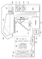
本実施形態においては、複数色のカラーパッチを有するチャートを撮影して、カラープロファイル作成用のカラーパッチ信号を得る撮像装置として、デジタル1眼レフカメラを適用する例を示す。図1は、本実施形態のデジタル1眼レフカメラの構成を示すブロック図である。図1において、100はカメラ本体、200は交換可能なレンズユニットである。
<First Embodiment>
Apparatus Configuration In this embodiment, an example in which a digital single lens reflex camera is applied as an imaging apparatus that captures a chart having a plurality of color patches and obtains a color patch signal for creating a color profile is shown. FIG. 1 is a block diagram showing the configuration of the digital single-lens reflex camera of this embodiment. In FIG. 1, 100 is a camera body, and 200 is a replaceable lens unit.
まず、レンズユニット200の構成について説明する。201〜203はレンズエレメントである。201は光軸上を前後に移動することで撮影画面のピント位置を調整するフォーカシングレンズ群である。202は光軸上を前後に移動することでレンズユニット200の焦点距離を変更し、撮影画面の変倍を行う変倍レンズ群である。203はテレセントリック性等のレンズ性能を向上させるための固定レンズである。204は絞りである。205は測距エンコーダであり、フォーカシングレンズ群201の位置を読み取り、被写体距離に相当する信号を発生する。206はレンズ制御部であり、カメラ本体100から送られた信号に基いて絞り204の開口径を変化させ、測距エンコーダ205から送られた信号に基いてフォーカシングレンズ群201を移動させる制御を行う。レンズ制御部206はまた、測距エンコーダ205で発生した被写体距離、変倍レンズ群202の位置情報に基く焦点距離、絞り204の開口径に基くFナンバー、等を含むレンズ情報をカメラ本体100に送信する。207はレンズユニット200とカメラ本体100との通信インターフェイスとなるマウント接点群である。
First, the configuration of the
次に、カメラ本体100の構成について説明する。101は主ミラーであり、ファインダ観察状態では撮影光路内に斜設され、撮影状態では撮影光路外に退避する。また、主ミラー101はハーフミラーとなっており、撮影光路内に斜設されているときは、後述する測距センサ103へ被写体からの光線の約半分を透過させる。104はレンズエレメント201〜203の予定結像面に配置されたファインダスクリーンであり、撮影者はアイピース107を通してこのファインダスクリーン104を観察することで、撮影画面を確認する。ここで、106はペンタプリズムであり、ファインダスクリーン104からの光線をアイピース107へ導くための光路変更を行う。また、105は透過型液晶素子からなるファインダ表示素子であり、例えば図4に示すような枠や、シャッタ速度、絞り値、露出補正量等の撮影情報を、撮影者がアイピース107を通して観察する画面中に表示させる。なお、図4に示す表示枠の詳細については後述する。
Next, the configuration of the
103は測距センサであり、主ミラー101の裏側に退避可能に設けられたサブミラー102を介して、レンズユニット200からの光束を取り込む。測距センサ103は取り込んだ光束の状態をカメラ制御部111に送り、カメラ制御部111はそれに基いてレンズユニット200の被写体に対するピント状態を判定する。続けてカメラ制御部111は、判定されたピント状態とレンズ制御部206から送られるフォーカシングレンズ群201の位置情報に基き、フォーカシングレンズ群201の動作方向および動作量を算出する。
108は測光センサであり、ファインダスクリーン104上に映された画面上の所定領域における明るさ乃至輝度の信号を発生し、カメラ制御部111に送信する。カメラ制御部111では、この測光センサ108から送信された信号値に基き、撮像センサ110への適切な露光量を決定する。
A
カメラ制御部111はさらに、撮影モード切替部114によって選択される撮影モードに応じて、上記適切な露光量となるよう絞り204における開口径、およびシャッタ109におけるシャッタ速度の制御を行う。撮影モードがシャッタスピード優先モードである場合は、カメラ制御部111は、パラメータ設定変更部115で設定されたシャッタ速度に対して上記の適切な露光量を得るように、絞り204の開口径を算出する。そして該算出値に基き、カメラ制御部111はレンズ制御部206に命令を送ることで、絞り204の開口径を調整する。同様に、撮影モードが絞り優先モードである場合は、設定された絞り値に対して上記の適切な露光量を得るように、シャッタ秒時を算出する。さらに、プログラムモードである場合は、カメラ制御部111は、上記の適切な露光量に対して予め定められたシャッタ速度と絞り値の組み合わせに従い、シャッタ速度と絞り値を決定する。
The
以上の処理は、シャッタスイッチ113の半押しにより開始される。このときレンズ制御部206は、カメラ制御部111が決定したフォーカシングレンズ群201の動作方向と動作量を目標として、測距エンコーダ205の示す位置情報が該目標動作量と一致するまで、フォーカシングレンズ群201を駆動する。
The above process is started by half-pressing the
次にシャッタスイッチ113を全押しすることにより、撮影シーケンスが開始される。撮影シーケンスの開始により、まず、主ミラー101とサブミラー102が折りたたまれて撮影光露外に退避する。続いて、カメラ制御部111による算出値に従い、レンズ制御部206が絞り204を絞り込む。続いてシャッタ109が、カメラ制御部111の算出したシャッタ速度に従い開放閉鎖する。この後、絞り204が開放され、続いて主ミラー101とサブミラー102が元位置に復帰する。
Next, when the
110は撮像センサであり、シャッタ109の開放中に蓄積された各ピクセルの輝度信号を、カメラ制御部111に転送する。撮像センサ110には、R,G,Bの3色からなるカラーフィルタがベイヤー配列状に配置されており、カメラ制御部111は、これらのR,G,Bフィルタの位置に相当する輝度信号から、R,G,Bの3チャンネルからなるカラー画像信号を形成する。そして、通常の撮影モードの場合には、カメラ制御部111が内部に予め格納されているカラープロファイルを用いて色変換を行い、適当な色空間にマッピングし、適切な形式の画像ファイルを作成する。ここで利用されるカラープロファイルがすなわち、本実施形態において撮影されたチャートの画像情報に基づいて、例えば外部のPCで作成されたものである。チャート撮影モードの場合には、カラープロファイルを用いた色変換および色空間へのマッピングを行わずに、適当な形式のファイルを作成する。
116はカメラ本体100の背面に設けられた表示部であり、撮影モード切替部114及びパラメータ設定変更部115による設定に基いて、設定状況を表示するとともに、撮影後にカメラ制御部111によって作成されたサムネール画像を表示する。
112は、取り外し可能なメモリーカードの記録再生部であり、撮影後にカメラ制御部111が作成した画像ファイルを、装填されたメモリーカードに記録する。
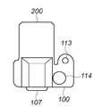
図2Aおよび図2Bは、本実施形態のデジタル1眼レフカメラの上面図および背面図である。図2A,Bにおいて、上述した図1と同様の構成には同一番号を付してある。すなわち、107はファインダアイピース、113はシャッタスイッチ、114は撮影モード切り替え部、115はパラメータ設定変更部、116は表示部である。 2A and 2B are a top view and a rear view of the digital single-lens reflex camera of the present embodiment. 2A and 2B, the same number is attached | subjected to the structure similar to FIG. 1 mentioned above. That is, 107 is a finder eyepiece, 113 is a shutter switch, 114 is a photographing mode switching unit, 115 is a parameter setting changing unit, and 116 is a display unit.
パラメータ設定変更部115は、表示部116の表示内容を切り替えるための切り替えボタン117を有する。さらに、表示部116上で選択箇所を上下左右方向に動かすための選択ボタン118a(上方向),118b(下方向),118c(右方向),118d(左方向)、を有する。そしてさらに、選択を決定するためのOKボタン119を有する。
The parameter
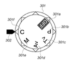
図3は、撮影モード切替部114の詳細を示す外観図である。図3において、301はモード設定ダイヤル、302はモード設定ダイヤル301の設定指標である。モード設定ダイヤル301上において、301aはカメラの電源オフ、301bはプログラムモード、301cはシャッタ優先モード、301dは絞り優先モード、の設定位置である。これらの撮影モードの詳細に関しては、既に説明したとおりである。301eは、撮影者がシャッタ速度と絞りを自由に選択するマニュアルモード設定位置であり、301fはチャート撮影モード設定位置である。
FIG. 3 is an external view showing details of the shooting
●ファインダ内表示
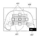
図4Aは、ファインダ表示素子105によるファインダ内表示を示す図である。図4Aにおいて、400はファインダ視野範囲を示す。ファインダ視野範囲400内において、401はチャート撮影モードの選択時に、チャートの位置指標として表示されるチャート撮影枠である。ユーザは、チャート撮影モード時に、撮影対象となるチャートがこのチャート撮影枠401に一致するように、画角を決定する。このときのチャートの撮影倍率は、レンズの周辺減光の影響を避けるために、ファインダ視野面積の約1/4を占める程度が望ましいが、これに限定されるものではない。
In-Finder Display FIG. 4A is a diagram showing in-finder display by the
402〜406はそれぞれ、オートフォーカス指標である。また407は、チャート撮影モード時における最適な撮影距離を示す撮影距離表示部である。
図4Bは、チャート撮影モード選択時における表示部116の表示例を示す。同図において、408は撮影するチャートが予め定められた「チャート1」であることを選択するチャート1選択部、409は同じく「チャート2」であることを選択するチャート2選択部である。これらの選択は、選択ボタン118aや118bを押下することによって行われ、これらの間の移動方向は矢印表示411,412で示される。選択された選択部はハイライト表示される。同図においては、チャート1選択部408が選択された例を示している。410は、表示内容を直前の表示画面に切り替えるための選択部である。それぞれの選択が終了すると、矢印表示412に示される方向に選択ボタン118cを押下することで選択内容が決定される。さらに決定表示413に示されるようにOKボタン119を押下することによって最終的なチャート種別が特定され、撮影準備状態となる。このように本実施形態においては、選択可能な複数のチャート種別のうち、ユーザ指示に応じてチャートの種別が選択・特定される。
FIG. 4B shows a display example of the
図5Aは、「チャート1」に対するファインダ表示例を示し、図5Bは「チャート2」に対するファインダー表示例を示す。ここで「チャート1」と「チャート2」ではチャートのサイズが異なり、「チャート1」のサイズは「チャート2」のサイズ例えば1.5倍である。そのため、これらチャートを等しい大きさに撮影するためには、同じ撮影レンズを用いる場合、撮影距離の比が3:2となる。したがって、撮影距離表示部407に表示される距離は、装着された撮影レンズ(レンズユニット200)の焦点距離に従い、「チャート1」に対しては図5Aに示す様に例えば1.5m、「チャート2」に対しては図5Bに示す様に例えば1mとなる。このとき表示部116には、「チャート1」に対しては図5C、「チャート2」に対しては図5D、に示すメッセージがそれぞれ表示される。
5A shows a finder display example for “Chart 1”, and FIG. 5B shows a finder display example for “Chart 2”. Here, “Chart 1” and “Chart 2” have different chart sizes. The size of “Chart 1” is 1.5 times the size of “Chart 2”, for example. Therefore, in order to photograph these charts to the same size, when using the same photographing lens, the ratio of the photographing distance is 3: 2. Accordingly, the distance displayed on the shooting
図5A〜図5Dに示すように本実施形態によれば、チャート撮影モード時に被写体として設定されたチャート種別に応じて、撮影レンズに基づく適切な撮影距離をユーザに対して提示する。ユーザはこの提示された撮影距離を実現するように、実際にチャート撮影を行う位置を決定することができる。 As shown in FIGS. 5A to 5D, according to the present embodiment, an appropriate shooting distance based on the shooting lens is presented to the user according to the chart type set as the subject in the chart shooting mode. The user can determine the position at which the chart photographing is actually performed so as to realize the presented photographing distance.
●チャート撮影処理
図6は、カメラ制御部111によって制御される、チャート撮影モード時における撮影準備処理を示すフローチャートである。モード設定ダイヤル301が電源オフ位置301a以外の位置に設定されることにより、本アルゴリズムは開始する。
Chart Shooting Process FIG. 6 is a flowchart showing a shooting preparation process in the chart shooting mode, which is controlled by the
まずステップS101において、モード設定ダイヤル301がチャート撮影モード位置301fに設定されているか否かを判定し、判定されない場合は開始状態をキープする。チャート撮影モード位置301fへの設定が判定されると、ステップS102に進んで表示部116にチャート選択画面(図4B)を表示する。
First, in step S101, it is determined whether or not the
次にステップS103において、カメラ制御部111はレンズ制御部206から撮影レンズ(レンズユニット200)の焦点距離情報を取得し、2種類のチャートそれぞれに適当な撮影距離を算出する。なお、ここで撮影距離を得るために、チャート種別とレンズ種別に応じた適当な撮影距離を記載したテーブルを予め用意しておいても良い。
In step S103, the
そしてステップS104において、ステップS102で「チャート1」が選択されたか否かを判定し、「チャート1」が選択されていた場合はステップS106に進んでファインダ表示素子105にファインダー枠を表示する。そしてステップS107で、ステップS103で算出した「チャート1」に適当な撮影距離を、ファインダ表示素子105の撮影距離表示部407とカメラの表示部116に表示することによってユーザに報知し、ステップS110に移る。
In step S104, it is determined whether or not “chart 1” has been selected in step S102. If “chart 1” has been selected, the process proceeds to step S106 to display a finder frame on the
一方、「チャート1」が選択されていなかった場合は、ステップS105において、ステップS102で「チャート2」が選択されたか否かを判定する。ここで「チャート2」が選択されていた場合はステップS108に進んでファインダ表示素子105にファインダー枠を表示する。そしてステップS109で、ステップS103で算出した「チャート2」に適当な撮影距離を、ファインダ表示素子105の撮影距離表示部407とカメラの表示部116に表示することによってユーザに報知し、ステップS110に移る。
On the other hand, if “Chart 1” has not been selected, it is determined in Step S105 whether or not “Chart 2” has been selected in Step S102. If “chart 2” is selected here, the process proceeds to step S108 to display a finder frame on the
一方、「チャート2」も選択されなかった場合は、ステップS102に戻る。 On the other hand, if “Chart 2” is not selected, the process returns to step S102.
そしてステップS110において、チャート撮影に適当な自動露光(AE)とオートフォーカス(AF)のモードが設定され、ステップS111で撮影準備段階となって本アルゴリズムを終了する。 In step S110, an automatic exposure (AE) mode and an autofocus (AF) mode suitable for chart shooting are set. In step S111, the present algorithm is terminated in the shooting preparation stage.
ユーザは、以上のようにチャート種別に応じて提示された撮影距離に基づいて実際の撮影位置を決定し、シャッタスイッチ113を押下することにより、上述した撮影シーケンスが開始される。
The user determines the actual shooting position based on the shooting distance presented in accordance with the chart type as described above, and presses the
以上説明したように本実施形態によれば、カラープロファイル作成を目的としたチャート撮影を行う際に、撮影対象となるチャート種をユーザが明確に指定することにより、最適な撮影距離を得ることができる。したがって、常に正しい自動露光の設定と、正確なピント、正確な撮影倍率による撮影を行うことが可能となり、チャート撮影経験の少ないユーザであっても、カラープロファイル作成に必要な正確なチャート画像を容易に獲得することができる。そしてその結果として、チャートの撮影画像情報を用いて作成するカラープロファイルの精度向上が期待できる。 As described above, according to the present embodiment, when taking a chart for the purpose of creating a color profile, it is possible to obtain an optimum shooting distance by the user clearly specifying the chart type to be shot. it can. Therefore, it is possible to always set the correct automatic exposure, perform accurate focusing, and capture with an accurate shooting magnification, so that even users with little chart shooting experience can easily obtain the correct chart image necessary for color profile creation. Can be earned. As a result, an improvement in the accuracy of the color profile created using the captured image information of the chart can be expected.
<変形例>
本実施形態では、レンズ交換式デジタル一眼レフカメラを例として説明を行ったが、カメラの形式としてはこれに限るものではない。たとえば、レンズ交換式レンジファインダーデジタルカメラや、レンズ固定のコンパクトタイプのデジタルカメラ、デジタルビデオカメラ等であっても良い。また、ファインダ表示素子として透過型液晶素子を例として説明したが、発光ダイオードによりファインダスクリーンを照明することでチャート枠を表示する方法によっても、本発明は実施できる。さらに、光学ファインダを持たず、液晶表示素子やエレクトロルミネッセンス素子上にファインダ画像、チャート枠、チャート選択画面を表示するなど、他のファインダ構成、表示部構成によっても、本発明は実施可能である。
<Modification>
In the present embodiment, the interchangeable lens type digital single-lens reflex camera has been described as an example. However, the camera format is not limited to this. For example, an interchangeable lens rangefinder digital camera, a compact digital camera with a fixed lens, a digital video camera, or the like may be used. Further, although the transmissive liquid crystal element has been described as an example of the finder display element, the present invention can also be implemented by a method of displaying a chart frame by illuminating the finder screen with a light emitting diode. Furthermore, the present invention can be implemented by other finder configurations and display unit configurations, such as displaying a finder image, a chart frame, and a chart selection screen on a liquid crystal display element or an electroluminescence element without an optical finder.
<他の実施形態>
以上、実施形態例を詳述したが、本発明は例えば、システム、装置、方法、プログラム若しくは記録媒体(記憶媒体)等としての実施態様をとることが可能である。具体的には、複数の機器(例えば、ホストコンピュータ、インタフェース機器、撮像装置、webアプリケーション等)から構成されるシステムに適用しても良いし、また、一つの機器からなる装置に適用しても良い。
<Other embodiments>
Although the embodiment has been described in detail above, the present invention can take an embodiment as a system, apparatus, method, program, recording medium (storage medium), or the like. Specifically, the present invention may be applied to a system composed of a plurality of devices (for example, a host computer, an interface device, an imaging device, a web application, etc.), or may be applied to a device composed of a single device. good.
尚本発明は、前述した実施形態の機能を実現するソフトウェアプログラムを、システムあるいは装置に直接あるいは遠隔から供給し、そのシステムあるいは装置のコンピュータが該供給されたプログラムコードを読み出して実行することによっても達成される。なお、この場合のプログラムとは、コンピュータ読取可能であり、実施形態において図に示したフローチャートに対応したプログラムである。 The present invention also provides a software program that realizes the functions of the above-described embodiments directly or remotely to a system or apparatus, and the system or apparatus computer reads out and executes the supplied program code. Achieved. The program in this case is a computer-readable program that corresponds to the flowchart shown in the drawing in the embodiment.
従って、本発明の機能処理をコンピュータで実現するために、該コンピュータにインストールされるプログラムコード自体も本発明を実現するものである。つまり、本発明は、本発明の機能処理を実現するためのコンピュータプログラム自体も含まれる。 Accordingly, since the functions of the present invention are implemented by computer, the program code installed in the computer also implements the present invention. In other words, the present invention includes a computer program itself for realizing the functional processing of the present invention.
その場合、プログラムの機能を有していれば、オブジェクトコード、インタプリタにより実行されるプログラム、OSに供給するスクリプトデータ等の形態であっても良い。 In that case, as long as it has the function of a program, it may be in the form of object code, a program executed by an interpreter, script data supplied to the OS, or the like.
プログラムを供給するための記録媒体としては、以下に示す媒体がある。例えば、フロッピー(登録商標)ディスク、ハードディスク、光ディスク、光磁気ディスク、MO、CD-ROM、CD-R、CD-RW、磁気テープ、不揮発性のメモリカード、ROM、DVD(DVD-ROM,DVD-R)などである。 Recording media for supplying the program include the following media. For example, floppy disk, hard disk, optical disk, magneto-optical disk, MO, CD-ROM, CD-R, CD-RW, magnetic tape, nonvolatile memory card, ROM, DVD (DVD-ROM, DVD- R).
プログラムの供給方法としては、以下に示す方法も可能である。すなわち、クライアントコンピュータのブラウザからインターネットのホームページに接続し、そこから本発明のコンピュータプログラムそのもの(又は圧縮され自動インストール機能を含むファイル)をハードディスク等の記録媒体にダウンロードする。また、本発明のプログラムを構成するプログラムコードを複数のファイルに分割し、それぞれのファイルを異なるホームページからダウンロードすることによっても実現可能である。つまり、本発明の機能処理をコンピュータで実現するためのプログラムファイルを複数のユーザに対してダウンロードさせるWWWサーバも、本発明に含まれるものである。 As a program supply method, the following method is also possible. That is, the browser of the client computer is connected to a homepage on the Internet, and the computer program itself (or a compressed file including an automatic installation function) of the present invention is downloaded to a recording medium such as a hard disk. It can also be realized by dividing the program code constituting the program of the present invention into a plurality of files and downloading each file from a different homepage. That is, a WWW server that allows a plurality of users to download a program file for realizing the functional processing of the present invention on a computer is also included in the present invention.
また、本発明のプログラムを暗号化してCD-ROM等の記憶媒体に格納してユーザに配布し、所定の条件をクリアしたユーザに対し、インターネットを介してホームページから暗号化を解く鍵情報をダウンロードさせることも可能である。すなわち該ユーザは、その鍵情報を使用することによって暗号化されたプログラムを実行し、コンピュータにインストールさせることができる。 In addition, the program of the present invention is encrypted, stored in a storage medium such as a CD-ROM, distributed to users, and key information for decryption is downloaded from a homepage via the Internet to users who have cleared predetermined conditions. It is also possible to make it. That is, the user can execute the encrypted program by using the key information and install it on the computer.
また、コンピュータが、読み出したプログラムを実行することによって、前述した実施形態の機能が実現される。さらに、そのプログラムの指示に基づき、コンピュータ上で稼動しているOSなどが、実際の処理の一部または全部を行い、その処理によっても前述した実施形態の機能が実現され得る。 Further, the functions of the above-described embodiments are realized by the computer executing the read program. Furthermore, based on the instructions of the program, an OS or the like running on the computer performs part or all of the actual processing, and the functions of the above-described embodiments can also be realized by the processing.
さらに、記録媒体から読み出されたプログラムが、コンピュータに挿入された機能拡張ボードやコンピュータに接続された機能拡張ユニットに備わるメモリに書き込まれた後、実行されることによっても、前述した実施形態の機能が実現される。すなわち、該プログラムの指示に基づき、その機能拡張ボードや機能拡張ユニットに備わるCPUなどが実際の処理の一部または全部を行うことが可能である。 Further, the program read from the recording medium is written in a memory provided in a function expansion board inserted into the computer or a function expansion unit connected to the computer, and then executed, so that the program of the above-described embodiment can be obtained. Function is realized. That is, based on the instructions of the program, the CPU provided in the function expansion board or function expansion unit can perform part or all of the actual processing.
Claims (8)
前記チャートの種別を特定するチャート種別の特定手段と、
前記撮影レンズの焦点距離を取得する焦点距離の取得手段と、
前記焦点距離に基づいて、前記チャート種別に対する撮影距離を決定する撮影距離の決定手段と、
前記撮影距離を報知する報知手段と、
を有することを特徴とする撮像装置。 An imaging device that captures a chart having a plurality of color patches with a photographing lens and obtains a color patch signal for creating a color profile,
A chart type specifying means for specifying the type of the chart;
A focal length acquisition means for acquiring a focal length of the photographing lens;
A shooting distance determining means for determining a shooting distance for the chart type based on the focal length;
An informing means for informing the shooting distance;
An imaging device comprising:
を有することを特徴とする請求項1乃至3のいずれか1項に記載の撮像装置。 Further, a finder display means for displaying a chart photographing frame serving as a position index of the chart in the field of view of the finder,
The imaging apparatus according to claim 1, wherein the imaging apparatus includes:
前記チャート種別の特定手段、前記焦点距離の取得手段、前記撮影距離の決定手段、および前記報知手段は、前記チャート撮影モードが設定されている場合に機能することを特徴とする請求項1乃至4のいずれか1項に記載の撮像装置。 Furthermore, it has mode setting means for setting the chart shooting mode,
5. The chart type identification unit, the focal length acquisition unit, the shooting distance determination unit, and the notification unit function when the chart shooting mode is set. The imaging device according to any one of the above.
前記チャートの種別を特定するチャート種別の特定ステップと、
前記撮影レンズの焦点距離を取得する焦点距離の取得ステップと、
前記チャート種別に対する撮影距離を、前記焦点距離に基づいて取得する撮影距離の取得ステップと、
前記撮影距離を報知する報知ステップと、
を有することを特徴とする撮像装置の制御方法。 A method for controlling an image pickup apparatus that obtains a color patch signal for creating a color profile by photographing a chart having color patches of a plurality of colors with a photographing lens,
A chart type identifying step for identifying the chart type;
A focal length obtaining step for obtaining a focal length of the photographing lens;
An imaging distance acquisition step of acquiring an imaging distance for the chart type based on the focal length;
An informing step for informing the shooting distance;
A control method for an imaging apparatus, comprising:
Priority Applications (2)
| Application Number | Priority Date | Filing Date | Title |
|---|---|---|---|
| JP2007298590A JP2009124601A (en) | 2007-11-16 | 2007-11-16 | Imaging device and its control method |
| US12/269,307 US8345140B2 (en) | 2007-11-16 | 2008-11-12 | Image capturing apparatus and method of controlling same |
Applications Claiming Priority (1)
| Application Number | Priority Date | Filing Date | Title |
|---|---|---|---|
| JP2007298590A JP2009124601A (en) | 2007-11-16 | 2007-11-16 | Imaging device and its control method |
Publications (2)
| Publication Number | Publication Date |
|---|---|
| JP2009124601A true JP2009124601A (en) | 2009-06-04 |
| JP2009124601A5 JP2009124601A5 (en) | 2010-11-04 |
Family
ID=40641517
Family Applications (1)
| Application Number | Title | Priority Date | Filing Date |
|---|---|---|---|
| JP2007298590A Withdrawn JP2009124601A (en) | 2007-11-16 | 2007-11-16 | Imaging device and its control method |
Country Status (2)
| Country | Link |
|---|---|
| US (1) | US8345140B2 (en) |
| JP (1) | JP2009124601A (en) |
Families Citing this family (2)
| Publication number | Priority date | Publication date | Assignee | Title |
|---|---|---|---|---|
| USD609714S1 (en) * | 2007-03-22 | 2010-02-09 | Fujifilm Corporation | Electronic camera |
| US8194136B1 (en) | 2009-01-26 | 2012-06-05 | Amazon Technologies, Inc. | Systems and methods for lens characterization |
Family Cites Families (15)
| Publication number | Priority date | Publication date | Assignee | Title |
|---|---|---|---|---|
| JPS4714934U (en) * | 1971-03-18 | 1972-10-21 | ||
| US5659823A (en) * | 1990-08-29 | 1997-08-19 | Minolta Camera Kabushiki Kaisha | Camera |
| JPH11352541A (en) * | 1998-06-09 | 1999-12-24 | Minolta Co Ltd | Camera |
| US7570282B1 (en) * | 1998-12-09 | 2009-08-04 | Aptina Imaging Corporation | Color correction of multiple colors using a calibrated technique |
| JP3863327B2 (en) * | 1999-03-15 | 2006-12-27 | 富士フイルムホールディングス株式会社 | Digital still camera with composition advice function and operation control method thereof |
| JP2001045516A (en) * | 1999-08-03 | 2001-02-16 | Olympus Optical Co Ltd | Color reproduction system |
| JP2002281356A (en) * | 2001-03-21 | 2002-09-27 | Minolta Co Ltd | Photographing equipment, information providing device and information presentation system |
| JP2003015019A (en) * | 2001-06-27 | 2003-01-15 | Minolta Co Ltd | Device for detecting object and camera |
| JP4007016B2 (en) | 2002-02-21 | 2007-11-14 | コニカミノルタセンシング株式会社 | Color reproduction characteristic measuring apparatus and color reproduction characteristic measuring method |
| US20030169350A1 (en) * | 2002-03-07 | 2003-09-11 | Avi Wiezel | Camera assisted method and apparatus for improving composition of photography |
| US7480083B2 (en) * | 2002-07-30 | 2009-01-20 | Canon Kabushiki Kaisha | Image processing system, apparatus, and method, and color reproduction method |
| KR100503039B1 (en) * | 2002-11-25 | 2005-07-22 | 삼성테크윈 주식회사 | Method to control operation of digital camera for user to easily take an identification photograph |
| EP1659783A3 (en) * | 2004-11-19 | 2006-05-31 | Fujinon Corporation | Af-area display apparatus and af-area operation apparatus |
| JP4471373B2 (en) | 2004-12-27 | 2010-06-02 | キヤノン株式会社 | Imaging apparatus and control method thereof |
| TW200804947A (en) * | 2006-07-06 | 2008-01-16 | Asia Optical Co Inc | Method of distance estimation to be implemented using a digital camera |
-
2007
- 2007-11-16 JP JP2007298590A patent/JP2009124601A/en not_active Withdrawn
-
2008
- 2008-11-12 US US12/269,307 patent/US8345140B2/en not_active Expired - Fee Related
Also Published As
| Publication number | Publication date |
|---|---|
| US20090128680A1 (en) | 2009-05-21 |
| US8345140B2 (en) | 2013-01-01 |
Similar Documents
| Publication | Publication Date | Title |
|---|---|---|
| KR100770772B1 (en) | Image sensing apparatus and control method thereof | |
| JP4644883B2 (en) | Imaging device | |
| US8274598B2 (en) | Image capturing apparatus and control method therefor | |
| US7769287B2 (en) | Image taking apparatus and image taking method | |
| US7978254B2 (en) | Image capturing apparatus, its controlling method, and program | |
| US8059183B2 (en) | Image sensing apparatus and method for controlling the same | |
| JP2009081808A (en) | Device, method and program for controlling photographing, and photographing apparatus | |
| JP5068690B2 (en) | Image recording apparatus and method | |
| JP4284440B2 (en) | Electronic camera | |
| JP2009048136A (en) | Focusing device and focusing method | |
| JP5432664B2 (en) | Imaging device | |
| JP5210121B2 (en) | Imaging apparatus and control method thereof | |
| JP2013128251A (en) | Imaging device and program | |
| JP5159536B2 (en) | Imaging apparatus, control method thereof, and program | |
| JP4941141B2 (en) | Imaging device | |
| JP2009124602A (en) | Imaging apparatus, and control method thereof | |
| JP2009124601A (en) | Imaging device and its control method | |
| JP2009033386A (en) | Photographing device and method | |
| JP2019029778A (en) | Imaging apparatus, image processing apparatus, image processing method | |
| JP2007028486A (en) | Digital camera | |
| JP2005189887A (en) | Camera device | |
| JP2007074402A (en) | Display device, display operation device, processor, photographing device, and display method | |
| JP2009086036A (en) | Imaging device and control method for imaging device | |
| JP4888068B2 (en) | Electronic camera | |
| JP5400942B2 (en) | Image recording apparatus and method |
Legal Events
| Date | Code | Title | Description |
|---|---|---|---|
| A521 | Request for written amendment filed |
Free format text: JAPANESE INTERMEDIATE CODE: A523 Effective date: 20100915 |
|
| A621 | Written request for application examination |
Free format text: JAPANESE INTERMEDIATE CODE: A621 Effective date: 20100915 |
|
| A761 | Written withdrawal of application |
Free format text: JAPANESE INTERMEDIATE CODE: A761 Effective date: 20110831 |