JP5210121B2 - Imaging apparatus and control method thereof - Google Patents
Imaging apparatus and control method thereof Download PDFInfo
- Publication number
- JP5210121B2 JP5210121B2 JP2008280278A JP2008280278A JP5210121B2 JP 5210121 B2 JP5210121 B2 JP 5210121B2 JP 2008280278 A JP2008280278 A JP 2008280278A JP 2008280278 A JP2008280278 A JP 2008280278A JP 5210121 B2 JP5210121 B2 JP 5210121B2
- Authority
- JP
- Japan
- Prior art keywords
- chart
- subject
- display range
- photographing
- color
- Prior art date
- Legal status (The legal status is an assumption and is not a legal conclusion. Google has not performed a legal analysis and makes no representation as to the accuracy of the status listed.)
- Expired - Fee Related
Links
Images


Description
本発明は撮像装置およびその制御方法に関し、特に、複数色のカラーパッチを有するチャートを撮影して、カラープロファイル作成用のカラーパッチ信号を得る撮像装置およびその制御方法に関する。 The present invention relates to an imaging apparatus and a control method thereof, and more particularly to an imaging apparatus that captures a chart having a plurality of color patches and obtains a color patch signal for creating a color profile, and a control method thereof.
一般に普及しているデジタルカメラにおいては、撮影画像データにおける再現色が、被写体の色に対して忠実な色、または好ましい色など、観察者にとって最適な色となるように色変換処理が行われている。ところが、被写体の色は、被写体を照らす光源によって大きく異なるものである。したがって、ある光源下で最適な色再現が得られるように設定された色変換処理であっても、異なる光源下で撮影された画像データに適用すると、必ずしも最適な再現色は得られない。 In general digital cameras, color conversion processing is performed so that the reproduced color in the captured image data is a color that is faithful to the color of the subject or a preferable color such as a preferable color for the observer. Yes. However, the color of the subject varies greatly depending on the light source that illuminates the subject. Therefore, even if the color conversion processing is set to obtain an optimum color reproduction under a certain light source, the optimum reproduction color is not necessarily obtained when applied to image data photographed under a different light source.
そこでデジタルカメラにおいては、色変換処理の前処理として、ホワイトバランス調整が行われている。ところが、デジタルカメラのセンサが出力するR,G,B等のカラー情報は、必ずしも人間が知覚する3刺激値と対応しない。これは、デジタルカメラにおけるR,G,Bの各画素の分光感度が等色関数と一致しないことに起因する。もしも、この分光感度が等色関数と一致するならば、ホワイトバランスを適切にとりさえすれば、どのような光源下であっても、1つの最適な色変換処理によって最適な色再現を得ることが可能である。ところが、実際には分光感度は等色関数と異なるため、より精度の高い色変換処理を行うためには、光源に応じて異なる色再現処理を行う必要がある。 Therefore, in the digital camera, white balance adjustment is performed as a pre-process of the color conversion process. However, color information such as R, G, and B output from the sensor of the digital camera does not necessarily correspond to the tristimulus values perceived by humans. This is because the spectral sensitivities of the R, G, and B pixels in the digital camera do not match the color matching function. If this spectral sensitivity matches the color matching function, an optimal color reproduction can be obtained by one optimal color conversion process under any light source, as long as the white balance is appropriately adjusted. Is possible. However, since the spectral sensitivity is actually different from the color matching function, it is necessary to perform different color reproduction processing depending on the light source in order to perform more accurate color conversion processing.
光源に応じて異なる色再現処理を行うためには、それぞれの光源において、色変換を行うルックアップテーブル等のカラープロファイルを用意する必要がある。このカラープロファイルの作成方法としては、予め用意されている、複数のカラーパッチからなるチャートを撮影し、各カラーパッチの撮影データに基づいて作成する方法が知られている(例えば、特許文献1参照)。
上記従来のカラープロファイルの作成方法においては、カラーパッチが正確に撮影されていることが前提となっている。したがって、カラーパッチが正確に撮影されていない場合には、例えば以下に挙げるような問題が生じ、作成したカラープロファイルの精度が悪化したり、または作成自体が不可能となってしまったりする。 The conventional color profile creation method is based on the premise that the color patch has been photographed accurately. Therefore, when the color patch is not photographed correctly, for example, the following problems occur, and the accuracy of the created color profile is deteriorated, or the creation itself is impossible.
・チャートが斜めになって撮影されてしまい、カラーパッチのデータを抽出することが困難になる。 -The chart is shot at an angle, making it difficult to extract color patch data.
・撮影時の画角が適正でなく、レンズの周辺光量落ちや収差の影響を受けてしまう。 -The angle of view at the time of shooting is not appropriate, and it is affected by a drop in the amount of light around the lens and aberration.
・露出不足によりデータに多くのノイズが乗ってしまう。 ・ There is a lot of noise on the data due to underexposure.
・ピント不良(ピンボケ)によりパッチデータにパッチ以外の周辺色のデータが混ざりこんでしまう。 -Data of peripheral colors other than the patch are mixed into the patch data due to poor focus (out of focus).
・チャートへの照明が適正でなく、照明むらの影響を受けてしまう。 ・ The lighting on the chart is not appropriate and is affected by uneven lighting.
・逆光条件などで撮影したことにより、レンズのフレアやゴーストが生じてしまう。 ・ Shooting under backlit conditions may cause lens flare and ghosting.
一般にカラープロファイルは、多くはパーソナルコンピュータ(PC)上で作成されるため、チャートの撮影現場において作られることは少ない。したがって、チャートの撮影を行った段階では撮影に失敗したことに気づかず、カラープロファイルを作成する段階になって失敗に気づくことも多い。このような場合には、再度撮影現場まで出向いて撮影を行う必要がある。特に屋外において被写体およびチャートを撮影した場合、撮影環境を後日に再現することはほぼ不可能であるため、チャートの撮影が失敗していると、該被写体の撮影画像に対して最適なカラープロファイルを作成することは不可能となってしまう。また、そもそもチャート撮影経験の少ないユーザが正確にチャート撮影を行うことは容易ではなかった。 In general, since a color profile is often created on a personal computer (PC), it is rarely created at a chart shooting site. Therefore, it is often not noticed that the photographing has failed at the stage where the chart is photographed, and at the stage of creating the color profile, the failure is often noticed. In such a case, it is necessary to go to the shooting site again and take a picture. In particular, when shooting a subject and a chart outdoors, it is almost impossible to reproduce the shooting environment at a later date, so if chart shooting fails, an optimal color profile for the shot image of the subject will be obtained. It will be impossible to create. In the first place, it is not easy for a user with little chart photography experience to accurately perform chart photography.
本発明は上述した問題を解決するためになされたものであり、カラープロファイル作成を目的としたチャート撮影を適切に行うことを容易に可能とする撮像装置およびその制御方法を提供することを目的とする。 The present invention has been made to solve the above-described problems, and an object of the present invention is to provide an imaging apparatus and a control method for the imaging apparatus that can easily perform chart photography for the purpose of creating a color profile. To do.
上記目的を達成するための一手段として、本発明の撮像装置は以下の構成を備える。 As a means for achieving the above object, an imaging apparatus of the present invention comprises the following arrangement.
すなわち、被写体を表示範囲内に表示するファインダ表示手段と、前記ファインダ表示手段の表示範囲内の複数箇所に対応する前記被写体との複数の距離を測定する測距手段と、前記表示範囲内の前記被写体の大きさを取得する取得手段と、前記測距手段によって測定された複数の距離から計算された最大の差と、前記取得手段によって取得された前記被写体の大きさとに基づいて、カラープロファイルを生成可能な複数のカラーパッチを有するチャートとして前記被写体が撮影可能であるか否かを判定する判定手段と、前記被写体が前記チャートとして撮影可能であると前記判定手段が判定した場合に、前記被写体を前記チャートとして撮影する撮影手段と、前記被写体が前記チャートとして撮影不可であると前記判定手段が判定した場合に、前記被写体が前記チャートとして撮影不可であることを示す通知を与える報知手段と、を有することを特徴とする。 That is, a distance measuring means for measuring the finder display means for displaying within the display subject, the plurality of distances between the subject corresponding to the plurality of locations within the display range of the finder display means, said within the display range obtaining means for obtaining the size of the subject, said the maximum of the difference thus calculated from the measured plurality of distances to the ranging means, and have size and based Dzu of the object obtained by the obtaining means, color profiles and determine the constant means the subject as charts having a plurality of color patches can be generated is you determine whether it can shoot, determination previous SL-size constant means that it is possible photographing the subject as the chart when a Kagete stage taking for photographing the subject as the chart, when said object is determined before SL-size constant means If it is not captured as the chart , Characterized by having a a notification means for providing notification that the subject is captured not as the chart.
以上の構成からなる本発明の撮像装置によれば、カラープロファイル作成を目的としたチャート撮影を適切に行うことが容易に可能となる。 According to the imaging apparatus of the present invention having the above-described configuration, it is possible to easily perform chart photography for the purpose of creating a color profile.
以下、添付の図面を参照して、本発明をその好適な実施形態に基づいて詳細に説明する。なお、以下の実施形態において示す構成は一例に過ぎず、本発明は図示された構成に限定されるものではない。 Hereinafter, the present invention will be described in detail based on preferred embodiments with reference to the accompanying drawings. The configurations shown in the following embodiments are merely examples, and the present invention is not limited to the illustrated configurations.
<第1実施形態>
●装置構成
本実施形態においては、複数色のカラーパッチを有するチャートを撮影して、カラープロファイル作成用のカラーパッチ信号を得る撮像装置として、デジタル1眼レフカメラを適用する例を示す。図1は、本実施形態のデジタル1眼レフカメラの構成を示すブロック図である。図1において、100はカメラ本体、200は交換可能なレンズユニットである。
<First Embodiment>
Apparatus Configuration In this embodiment, an example in which a digital single-lens reflex camera is applied as an imaging apparatus that captures a chart having a plurality of color patches and obtains a color patch signal for creating a color profile is shown. FIG. 1 is a block diagram showing the configuration of the digital single-lens reflex camera of this embodiment. In FIG. 1, 100 is a camera body, and 200 is a replaceable lens unit.
まず、レンズユニット200の構成について説明する。201〜203はレンズエレメントである。201は光軸上を前後に移動することで撮影画面のピント位置を調整するフォーカシングレンズ群である。202は光軸上を前後に移動することでレンズユニット200の焦点距離を変更し、撮影画面の変倍を行う変倍レンズ群である。203はテレセントリック性等のレンズ性能を向上させるための固定レンズである。204は絞りである。205は測距エンコーダであり、フォーカシングレンズ群201の位置を読み取り、被写体距離に相当する信号を発生する。206はレンズ制御部であり、カメラ本体100から送られた信号に基いて絞り204の開口径を変化させ、測距エンコーダ205から送られた信号に基いてフォーカシングレンズ群201を移動させる制御を行う。レンズ制御部206はまた、測距エンコーダ205で発生した被写体距離、変倍レンズ群202の位置情報に基く焦点距離、絞り204の開口径に基くFナンバー、等を含むレンズ情報をカメラ本体100に送信する。207はレンズユニット200とカメラ本体100との通信インターフェイスとなるマウント接点群である。
First, the configuration of the
次に、カメラ本体100の構成について説明する。101は主ミラーであり、ファインダ観察状態では撮影光路内に斜設され、撮影状態では撮影光路外に退避する。また、主ミラー101はハーフミラーとなっており、撮影光路内に斜設されているときは、後述する測距センサ103へ被写体からの光線の約半分を透過させる。104はレンズエレメント201〜203の予定結像面に配置されたファインダスクリーンであり、撮影者はアイピース107を通してこのファインダスクリーン104を観察することで、撮影画面を確認する。ここで、106はペンタプリズムであり、ファインダスクリーン104からの光線をアイピース107へ導くための光路変更を行う。また、105は透過型液晶素子からなるファインダ表示素子であり、例えば図4に示すような枠や、シャッタ速度、絞り値、露出補正量等の撮影情報を、撮影者がアイピース107を通して観察する画面中に表示させる。なお、図4に示す表示枠の詳細については後述する。
Next, the configuration of the
103は測距センサであり、主ミラー101の裏側に退避可能に設けられたサブミラー102を介して、レンズユニット200からの光束を取り込む。測距センサ103は取り込んだ光束の状態をカメラ制御部111に送り、カメラ制御部111はそれに基いてレンズユニット200の被写体に対するピント状態を判定する。続けてカメラ制御部111は、判定されたピント状態とレンズ制御部206から送られるフォーカシングレンズ群201の位置情報に基き、フォーカシングレンズ群201の動作方向および動作量を算出する。
108は測光センサであり、ファインダスクリーン104上に映された画面上の所定領域における明るさ乃至輝度の信号を発生し、カメラ制御部111に送信する。カメラ制御部111では、この測光センサ108から送信された信号値、すなわち測光結果に基き、撮像センサ110への適切な露光量を決定する。
A
カメラ制御部111はさらに、撮影モード切替部114によって選択される撮影モードに応じて、上記適切な露光量となるよう絞り204における開口径、およびシャッタ109におけるシャッタ速度の制御を行う。ここで、適切な露光量とは例えば、反射率18%のグレーの被写体を撮影した場合の撮像センサ110の出力値として、予めカメラ制御部111内に記憶されている。撮影モードがシャッタスピード優先モードである場合は、カメラ制御部111は、パラメータ設定変更部115で設定されたシャッタ速度に対して上記の適切な露光量を得るように、絞り204の開口径を算出する。そして該算出値に基き、カメラ制御部111はレンズ制御部206に命令を送ることで、絞り204の開口径を調整する。同様に、撮影モードが絞り優先モードである場合は、設定された絞り値に対して上記の適切な露光量を得るように、シャッタ秒時を算出する。さらに、プログラムモードである場合は、カメラ制御部111は、上記の適切な露光量に対して予め定められたシャッタ速度と絞り値の組み合わせに従い、シャッタ速度と絞り値を決定する。
The
以上の処理は、シャッタスイッチ113の半押しにより開始される。このときレンズ制御部206は、カメラ制御部111が決定したフォーカシングレンズ群201の動作方向と動作量を目標として、測距エンコーダ205の示す位置情報が該目標動作量と一致するまで、フォーカシングレンズ群201を駆動する。
The above process is started by half-pressing the
次にシャッタスイッチ113を全押しすることにより、撮影シーケンスが開始される。撮影シーケンスの開始により、まず、主ミラー101とサブミラー102が折りたたまれて撮影光露外に退避する。続いて、カメラ制御部111による算出値に従い、レンズ制御部206が絞り204を絞り込む。続いてシャッタ109が、カメラ制御部111の算出したシャッタ速度に従い開放閉鎖する。この後、絞り204が開放され、続いて主ミラー101とサブミラー102が元位置に復帰する。
Next, when the
110は撮像センサであり、シャッタ109の開放中に蓄積された各ピクセルの輝度信号を、カメラ制御部111に転送する。撮像センサ110には、R,G,Bの3色からなるカラーフィルタがベイヤー配列状に配置されており、カメラ制御部111は、これらのR,G,Bフィルタの位置に相当する輝度信号から、R,G,Bの3チャンネルからなるカラー画像信号を形成する。そして、通常の撮影モードの場合には、カメラ制御部111内に予め格納されているカラープロファイルにて色変換を行い、適当な色空間にマッピングし、適切な形式の画像ファイルを作成する。ここで利用されるカラープロファイルがすなわち、本実施形態において撮影されたチャート内における複数のカラーパッチ信号に基づいて、例えば外部のPCで作成されたものである。チャート撮影モードの場合には、カラープロファイルによる色変換および色空間へのマッピングを行わずに、適当な形式のファイルを作成する。
116はカメラ100の背面に設けられた表示部であり、撮影モード切替部114及びパラメータ設定変更部115による設定に基いて、設定状況を表示するとともに、撮影後にカメラ制御部111によって作成されたサムネール画像を表示する。
112は、取り外し可能なメモリーカードの記録再生部であり、撮影後にカメラ制御部111が作成した画像ファイルを、装填されたメモリーカードに記録する。
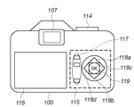
図2Aおよび図2Bは、本実施形態のデジタル1眼レフカメラの上面図および背面図である。図2A,Bにおいて、上述した図1と同様の構成には同一番号を付してある。すなわち、107はファインダアイピース、113はシャッタスイッチ、114は撮影モード切り替え部、115はパラメータ設定変更部、116は表示部である。 2A and 2B are a top view and a rear view of the digital single-lens reflex camera of the present embodiment. 2A and 2B, the same reference numerals are given to the same components as those in FIG. That is, 107 is a finder eyepiece, 113 is a shutter switch, 114 is a photographing mode switching unit, 115 is a parameter setting changing unit, and 116 is a display unit.
パラメータ設定変更部115は、表示部116の表示内容を切り替えるための切り替えボタン117を有する。さらに、表示部116上で選択箇所を上下左右方向に動かすための選択ボタン118a(上方向),118b(下方向),118c(右方向),118d(左方向)、を有する。そしてさらに、選択を決定するためのOKボタン119を有する。
The parameter
図3は、撮影モード切替部114の詳細を示す外観図である。図3において、301はモード設定ダイヤル、302はモード設定ダイヤル301の設定指標である。モード設定ダイヤル301上において、301aはカメラの電源オフ、301bはプログラムモード、301cはシャッタ優先モード、301dは絞り優先モード、の設定位置である。これらの撮影モードの詳細に関しては、既に説明したとおりである。301eは、撮影者がシャッタ速度と絞りを自由に選択するマニュアルモード設定位置であり、301fはチャート撮影モード設定位置である。
FIG. 3 is an external view showing details of the shooting
●ファインダ内表示
図4は、ファインダ表示素子105によるファインダ内表示を示す図である。図4において、400はファインダ視野範囲を示す。ファインダ視野範囲400内において、401はチャート撮影モードの選択時に、チャートの位置指標として表示されるチャート撮影枠である。ユーザは、チャート撮影モード時に、撮影対象となるチャートがこのチャート撮影枠401に一致するように、画角を決定する。このときのチャートの撮影倍率は、レンズの周辺減光の影響を避けるために、ファインダ視野面積の約1/4を占める程度が望ましいが、これに限定されるものではない。また、402は測光領域であり、チャート撮影モードにおいては、測光領域402においてスポット測光を行うことにより、チャートを撮影する上で最適な撮像センサ110への露光量を決定する。
In-Finder Display FIG. 4 is a diagram showing the in-finder display by the
403〜406はそれぞれ、チャート撮影枠401に重ねて設けられた、本実施形態における測距点としてのオートフォーカス指標である。本実施形態では、オートフォーカス指標403〜406におけるデフォーカス量の違いに基づいて各指標における被写体の距離の差を算出することにより、チャートが適切な位置に置かれているか否かを判定する。また407は、チャート撮影モード時にチャートが適切に撮影できるか否かの判定結果を表示するための判定結果表示部である。本実施形態においては、チャートが適切に撮影できると判定した場合には判定結果表示部407に「OK」を表示し、適切に撮影できないと判定した場合には「NG」を表示する。なお、判定結果の表示はこれに限るものでなく、ユーザにとって理解できるものであればどのようなものであっても良いことは言うまでもない。
●チャート撮影処理
図5は、カメラ制御部111によって制御される、チャート撮影モードによる撮影処理を示すフローチャートである。モード設定ダイヤル301がチャート撮影モード位置301fに設定された状態において、ユーザがシャッタスイッチ113を半押しすることにより、本アルゴリズムは開始する。
Chart Shooting Process FIG. 5 is a flowchart showing a shooting process in the chart shooting mode controlled by the
まずステップS101において、露出の決定処理(AE処理)、および、オートフォーカス処理(AF処理)を行う。露出の決定処理は、例えば既に述べた絞り優先モードと同様に、予め設定された絞り値に対して、上述した適切な露光量を得るシャッタ秒時を算出する。すなわち、測光センサ108で測光した図4の測光領域402における平均輝度が反射率18%の被写体に相当するものとして、撮像センサ110の出力が予め設定された値となるよう、シャッタ秒時を決定する。また、ステップS101におけるオートフォーカス処理は、既に測距センサ103の説明で述べたように、オートフォーカス指標403〜406のいずれか1点においてピントが合うよう、フォーカシングレンズ群201を駆動する。
First, in step S101, an exposure determination process (AE process) and an autofocus process (AF process) are performed. In the exposure determination process, for example, as in the aperture priority mode described above, the shutter time for obtaining the appropriate exposure amount described above is calculated for a preset aperture value. That is, the shutter time is determined so that the output of the
次にステップS102において、ステップS101で決定したシャッタ秒時に対し、撮影するチャートの種別に応じて補正を加える。具体的には、測光領域402付近に位置するパッチの平均の反射率が18%より明るいチャートの場合にはより明るく(シャッタ秒時を長時間に)変更する。逆に、測光領域402付近に該当するパッチの平均の反射率が18%より暗いチャートの場合にはより暗く(シャッタ秒時を短時間に)変更する。これらの補正量は、撮影するチャートの種別に応じて、予めカメラ制御部111内に記憶されているものとする。また、チャートの種別の特定方法としては例えば、撮影時にユーザによって選択・指示されるものとする。このように、チャートの種別によって露出を適正に補正することで、より適正なチャート画像を取得することが可能となる。すなわち、チャート画像内における複数のカラーパッチ情報を利用して作成するカラープロファイルの精度を向上させることが可能となる。
Next, in step S102, the shutter time determined in step S101 is corrected according to the type of chart to be photographed. Specifically, in the case of a chart in which the average reflectance of patches located near the
ステップS103では、測距エンコーダ205により発生した被写体距離d、変倍レンズ群202の位置情報に基く焦点距離f、絞り204の開口径に基くFナンバーを、レンズ制御部206から取得し、これらの情報に基づいて被写界深度oを算出する。なお、被写界深度oは例えば以下の式(1)〜(3)により算出することが可能であるが、これに限定するものではない。
In step S103, the subject distance d generated by the ranging

但し、式(1)においてσは許容錯乱円の径を示し、撮像センサ110における1ピクセルの大きさに相当する。
However, in the formula (1), σ represents the diameter of the allowable circle of confusion and corresponds to the size of one pixel in the
ステップS104では、被写体サイズhを算出する。ここで被写体サイズhとは、撮影するチャートの大きさを意味するものである。被写体サイズhは後段の判定ステップS106において参照され、この被写体サイズhが予め想定されるチャートの大きさと異なる場合に、被写体はチャートでは無いと判定される。 In step S104, the subject size h is calculated. Here, the subject size h means the size of the chart to be photographed. The subject size h is referred to in a determination step S106 at a later stage, and when the subject size h is different from the chart size assumed in advance, it is determined that the subject is not a chart.
図4におけるチャート撮影枠401の1辺の長さに対応した撮像センサ110上での長さをkとすると、被写体サイズhは例えば次式により算出される。
If the length on the
ステップS105では、図4における各オートフォーカス指標403〜406(以下、単に指標と称する)における、最大の測距距離差ΔLを算出する。ここではまず、指標403〜406の位置に対応する測距センサ103の出力値から、各指標403〜406の位置における被写体距離を推定し、次に、これらの被写体距離において、最大値と最小値の差分をとり、これをΔLとする。
In step S105, the maximum distance measurement distance difference ΔL is calculated for each of the
ステップS106は撮影判定ステップであり、上述した最大測距距離差ΔL、被写界深度o、被写体サイズh、被写体距離d、に基づき、被写体がチャートであるか否か、あるいはチャートの位置が適切であるか否かにより、撮影の可否を判定する。すなわち、まず被写体サイズhが予め設定された閾値Tm1より大きく、Tm2より小さい場合には、被写体のサイズが想定されるチャートの大きさと違うため、被写体はチャートでないと判断し、Falseのフラグを立てる。また、最大測距距離差ΔLが被写界深度oよりも大きい場合は、チャートの全面にピントの合った画像を取得できないためFalseのフラグを立てる。さらに、最大測距距離差ΔLが、予め設定された閾値TLより大きい場合は、被写体であるチャートがチャート撮影枠401の位置からずれていると想定されるためFalseのフラグを立てる。
Step S106 is a shooting determination step. Based on the above-mentioned maximum distance measurement difference ΔL, depth of field o, subject size h, subject distance d, whether or not the subject is a chart or the position of the chart is appropriate. Whether or not shooting is possible is determined based on whether or not it is. That is, first, when the subject size h is larger than the preset threshold value Tm1 and smaller than Tm2, the subject size is different from the assumed chart size, so it is determined that the subject is not a chart and a False flag is set. . If the maximum distance measurement difference ΔL is larger than the depth of field o, a false flag is set because an in-focus image cannot be acquired on the entire surface of the chart. Further, if the maximum distance measurement distance difference ΔL is larger than a preset threshold TL, it is assumed that the chart as the subject is deviated from the position of the
Falseのフラグが立った場合はステップS108に進み、判定結果表示部407に「NG」を表示し、撮影不可である旨をユーザに報知して処理を終了する。一方、判定ステップS106においてTrueのフラグが立った場合は、判定結果表示部407に「OK」を表示して撮影可能である旨をユーザに報知し、撮影処理を行うステップS110に進む。
If the False flag is set, the process proceeds to step S108, "NG" is displayed on the determination
撮影処理ステップS110は、ステップS109においてシャッタスイッチ113が全押しされたと判断した場合に実行される。撮影処理ステップS110においては、上述したように、ステップS101およびステップS102で決定した露光量に基いて撮像センサ110を露光し、取得した画像データを記録部112の記録メディアに記録する。
The photographing process step S110 is executed when it is determined in step S109 that the
図6Aは、チャート撮影モードにおいて、チャートが適切に撮影できると判断された場合のファインダ表示例を示す図である。同様に図6Bは、チャートが適切に撮影できないと判断された場合のファインダ表示例を示す図である。図6Bに示すように、被写体としてのチャートがチャート撮影枠401からずれている場合は、各オートフォーカス指標403〜406での測距センサ出力値が大きくことなることが予想されるため、最大測距距離差ΔLが所定の閾値TLよりも大きくなる。したがって、チャート撮影には不適切と判断され、「NG」を表示して処理を終了する。
FIG. 6A is a diagram illustrating a finder display example when it is determined that the chart can be appropriately captured in the chart capturing mode. Similarly, FIG. 6B is a diagram illustrating a finder display example when it is determined that the chart cannot be properly captured. As shown in FIG. 6B, when the chart as the subject is deviated from the
以上説明したように本実施形態によれば、カラープロファイル作成を目的としたチャート撮影を行う際に、チャート撮影が適切に行えるか否かを判断し、該判定結果を表示するとともに、撮影不可と判定された場合には撮影を禁止するように撮影制御を行う。詳細には、撮像範囲内の複数箇所、すなわち複数指標における測距結果に基づく判定により、チャートの位置ずれを防止することができる。また、絞り値を測距離に応じて決定することにより、撮影時のピントを適切にあわせることができる。また、測光値に対する露出量をチャートの種別に応じて補正することにより、適切な露光量によるチャート撮影が可能となる。これにより、常に正しいチャート位置、正確なピント、正しい画角によるチャート撮影を行うことができ、チャート撮影経験の少ないユーザであっても適切な撮影を行うことが容易に可能となる。そしてその結果として、チャートの撮影画像情報を用いて作成するカラープロファイルの精度向上が期待できる。 As described above, according to the present embodiment, when chart photographing for the purpose of creating a color profile is performed, it is determined whether or not chart photographing can be appropriately performed, the determination result is displayed, and the photographing is impossible. When the determination is made, shooting control is performed to prohibit shooting. Specifically, chart misalignment can be prevented by determination based on distance measurement results at a plurality of locations within the imaging range, that is, a plurality of indices. Further, by determining the aperture value according to the distance measurement, it is possible to appropriately adjust the focus at the time of shooting. In addition, by correcting the exposure amount with respect to the photometric value according to the type of chart, chart photographing with an appropriate exposure amount is possible. Thereby, it is possible to always perform chart photography with the correct chart position, accurate focus, and correct angle of view, and even a user with little chart photography experience can easily perform appropriate photography. As a result, an improvement in the accuracy of the color profile created using the captured image information of the chart can be expected.
<変形例>
本実施形態では、レンズ交換式デジタル一眼レフカメラを例として説明を行ったが、カメラの形式としてはこれに限るものではなく、たとえば、レンズ固定のコンパクトタイプのデジタルカメラや、デジタルビデオカメラであっても良い。また、ファインダ表示素子として透過型液晶素子を例として説明したが、発光ダイオードによりファインダスクリーンを照明することでチャート枠を表示する方法によっても、本発明は実施できる。さらに、光学ファインダを持たず、液晶表示素子やエレクトロルミネッセンス素子上にファインダ画像、チャート枠、チャート選択画面を表示するなど、他のファインダ構成、表示部構成によっても、本発明は実施可能である。
<Modification>
In the present embodiment, the interchangeable lens type digital single-lens reflex camera has been described as an example. However, the format of the camera is not limited to this, for example, a compact type digital camera with a fixed lens or a digital video camera. Also good. Further, although the transmissive liquid crystal element has been described as an example of the finder display element, the present invention can also be implemented by a method of displaying a chart frame by illuminating the finder screen with a light emitting diode. Furthermore, the present invention can be implemented by other finder configurations and display unit configurations, such as displaying a finder image, a chart frame, and a chart selection screen on a liquid crystal display element or an electroluminescence element without having an optical finder.
チャート撮影モードにおける露出の決定方法としては、本実施形態では絞り優先モードと同様として説明したが、これに限るものではなく、シャッタスピード優先モードやプログラムモード、マニュアルモードに類するものであっても良いことはいうまでもない。また、ユーザが露出決定方法や露出補正量を選択できるよう構成してもよい。ただし、図5のステップS102のようにチャートに適した補正を加える場合には、それぞれのモードに対応して予め決められた量が補正されるものとする。例えば、シャッタスピード優勢モードであれば絞り値、プログラムモードであれば絞り値とシャッタ秒時、マニュアルモードであればシャッタ秒時、がそれぞれ補正される。 In this embodiment, the exposure determination method in the chart photographing mode has been described as being the same as that in the aperture priority mode. However, the exposure determination method is not limited to this and may be similar to the shutter speed priority mode, the program mode, and the manual mode. Needless to say. Moreover, you may comprise so that a user can select the exposure determination method and exposure correction amount. However, when a correction suitable for the chart is applied as in step S102 of FIG. 5, a predetermined amount corresponding to each mode is corrected. For example, the aperture value is corrected in the shutter speed dominant mode, the aperture value and the shutter time are corrected in the program mode, and the shutter time is corrected in the manual mode.
また、本実施形態においては、最大測距距離差ΔL、被写界深度o、被写体サイズh、被写体距離dを算出することによって、チャート撮影が適切に行えるか否かを判断したが、これらパラメータの算出方法等は上述した方法に限らない。同様な判断結果を得られるものであれば、どのような方法によって算出されたパラメータであってもよい。また、これら全ての値を判断に利用する必要はなく、これらのうち少なくとも1つ以上に相当する量を用いて判断しても良い。さらに、その判断基準も判定ステップS106での例示に限定されるものではない。 Further, in the present embodiment, it is determined whether or not chart photographing can be appropriately performed by calculating the maximum distance measurement distance difference ΔL, the depth of field o, the subject size h, and the subject distance d. The calculation method and the like are not limited to the method described above. The parameter may be calculated by any method as long as a similar determination result can be obtained. Further, it is not necessary to use all these values for the determination, and determination may be made using an amount corresponding to at least one of these values. Further, the determination criterion is not limited to the example in the determination step S106.
<他の実施形態>
以上、実施形態例を詳述したが、本発明は例えば、システム、装置、方法、プログラム若しくは記録媒体(記憶媒体)等としての実施態様をとることが可能である。具体的には、複数の機器(例えば、ホストコンピュータ、インタフェース機器、撮像装置、webアプリケーション等)から構成されるシステムに適用しても良いし、また、一つの機器からなる装置に適用しても良い。
<Other embodiments>
Although the embodiment has been described in detail above, the present invention can take an embodiment as a system, apparatus, method, program, recording medium (storage medium), or the like. Specifically, the present invention may be applied to a system composed of a plurality of devices (for example, a host computer, an interface device, an imaging device, a web application, etc.), or may be applied to a device composed of a single device. good.
尚本発明は、前述した実施形態の機能を実現するソフトウェアプログラムを、システムあるいは装置に直接あるいは遠隔から供給し、そのシステムあるいは装置のコンピュータが該供給されたプログラムコードを読み出して実行することによっても達成される。なお、この場合のプログラムとは、コンピュータ読取可能であり、実施形態において図に示したフローチャートに対応したプログラムである。 The present invention also provides a software program that realizes the functions of the above-described embodiments directly or remotely to a system or apparatus, and the system or apparatus computer reads out and executes the supplied program code. Achieved. The program in this case is a computer-readable program that corresponds to the flowchart shown in the drawing in the embodiment.
従って、本発明の機能処理をコンピュータで実現するために、該コンピュータにインストールされるプログラムコード自体も本発明を実現するものである。つまり、本発明は、本発明の機能処理を実現するためのコンピュータプログラム自体も含まれる。 Accordingly, since the functions of the present invention are implemented by computer, the program code installed in the computer also implements the present invention. In other words, the present invention includes a computer program itself for realizing the functional processing of the present invention.
その場合、プログラムの機能を有していれば、オブジェクトコード、インタプリタにより実行されるプログラム、OSに供給するスクリプトデータ等の形態であっても良い。 In that case, as long as it has the function of a program, it may be in the form of object code, a program executed by an interpreter, script data supplied to the OS, or the like.
プログラムを供給するための記録媒体としては、以下に示す媒体がある。例えば、フロッピー(登録商標)ディスク、ハードディスク、光ディスク、光磁気ディスク、MO、CD-ROM、CD-R、CD-RW、磁気テープ、不揮発性のメモリカード、ROM、DVD(DVD-ROM,DVD-R)などである。 Recording media for supplying the program include the following media. For example, floppy disk, hard disk, optical disk, magneto-optical disk, MO, CD-ROM, CD-R, CD-RW, magnetic tape, nonvolatile memory card, ROM, DVD (DVD-ROM, DVD- R).
プログラムの供給方法としては、以下に示す方法も可能である。すなわち、クライアントコンピュータのブラウザからインターネットのホームページに接続し、そこから本発明のコンピュータプログラムそのもの(又は圧縮され自動インストール機能を含むファイル)をハードディスク等の記録媒体にダウンロードする。また、本発明のプログラムを構成するプログラムコードを複数のファイルに分割し、それぞれのファイルを異なるホームページからダウンロードすることによっても実現可能である。つまり、本発明の機能処理をコンピュータで実現するためのプログラムファイルを複数のユーザに対してダウンロードさせるWWWサーバも、本発明に含まれるものである。 As a program supply method, the following method is also possible. That is, the browser of the client computer is connected to a homepage on the Internet, and the computer program itself (or a compressed file including an automatic installation function) of the present invention is downloaded to a recording medium such as a hard disk. It can also be realized by dividing the program code constituting the program of the present invention into a plurality of files and downloading each file from a different homepage. That is, a WWW server that allows a plurality of users to download a program file for realizing the functional processing of the present invention on a computer is also included in the present invention.
また、本発明のプログラムを暗号化してCD-ROM等の記憶媒体に格納してユーザに配布し、所定の条件をクリアしたユーザに対し、インターネットを介してホームページから暗号化を解く鍵情報をダウンロードさせることも可能である。すなわち該ユーザは、その鍵情報を使用することによって暗号化されたプログラムを実行し、コンピュータにインストールさせることができる。 In addition, the program of the present invention is encrypted, stored in a storage medium such as a CD-ROM, distributed to users, and key information for decryption is downloaded from a homepage via the Internet to users who have cleared predetermined conditions. It is also possible to make it. That is, the user can execute the encrypted program by using the key information and install it on the computer.
また、コンピュータが、読み出したプログラムを実行することによって、前述した実施形態の機能が実現される。さらに、そのプログラムの指示に基づき、コンピュータ上で稼動しているOSなどが、実際の処理の一部または全部を行い、その処理によっても前述した実施形態の機能が実現され得る。 Further, the functions of the above-described embodiments are realized by the computer executing the read program. Furthermore, based on the instructions of the program, an OS or the like running on the computer performs part or all of the actual processing, and the functions of the above-described embodiments can also be realized by the processing.
さらに、記録媒体から読み出されたプログラムが、コンピュータに挿入された機能拡張ボードやコンピュータに接続された機能拡張ユニットに備わるメモリに書き込まれた後、実行されることによっても、前述した実施形態の機能が実現される。すなわち、該プログラムの指示に基づき、その機能拡張ボードや機能拡張ユニットに備わるCPUなどが実際の処理の一部または全部を行うことが可能である。 Further, the program read from the recording medium is written in a memory provided in a function expansion board inserted into the computer or a function expansion unit connected to the computer, and then executed, so that the program of the above-described embodiment can be obtained. Function is realized. That is, based on the instructions of the program, the CPU provided in the function expansion board or function expansion unit can perform part or all of the actual processing.
Claims (7)
前記ファインダ表示手段の表示範囲内の複数箇所に対応する前記被写体との複数の距離を測定する測距手段と、
前記表示範囲内の前記被写体の大きさを取得する取得手段と、
前記測距手段によって測定された複数の距離から計算された最大の差と、前記取得手段によって取得された前記被写体の大きさとに基づいて、カラープロファイルを生成可能な複数のカラーパッチを有するチャートとして前記被写体が撮影可能であるか否かを判定する判定手段と、
前記被写体が前記チャートとして撮影可能であると前記判定手段が判定した場合に、前記被写体を前記チャートとして撮影する撮影手段と、
前記被写体が前記チャートとして撮影不可であると前記判定手段が判定した場合に、前記被写体が前記チャートとして撮影不可であることを示す通知を与える報知手段と、
を有することを特徴とする撮像装置。 Finder display means for displaying the subject within the display range ;
Ranging means for measuring a plurality of distances to the subject corresponding to a plurality of locations within the display range of the finder display means ;
Obtaining means for obtaining the size of the subject within the display range;
It has a maximum difference thus calculated from the measured plurality of distances to the distance measuring means, and have groups Dzu to the size of the object obtained by the obtaining means, a plurality of color patches that can produce a color profile and determine the constant means the subject you determine whether it is capable of capturing a chart,
When the subject is determined prior SL-size constant means that it is possible photographed as the chart, and Kagete stage Taking for photographing the subject as the chart,
When the subject is determined prior SL-size constant means when there shooting impossible as the chart, and a notification means for providing notification that the subject is captured not as the chart,
An imaging device comprising:
前記測距手段は、前記表示範囲内の前記チャート撮影枠の複数箇所に対応する前記被写体との距離を測定する
ことを特徴とする請求項1に記載の撮像装置。 The finder display means displays a chart photographing frame for guiding the subject to a photographing position in order to photograph the subject as the chart within the display range ,
The imaging apparatus according to claim 1, wherein the distance measuring means measures distances to the subject corresponding to a plurality of locations of the chart photographing frame within the display range .
前記判定手段は、前記最大の差が前記被写界深度よりも大きい場合に、前記被写体は前記チャートとして撮影不可であると判定することを特徴とする請求項1乃至3のいずれか1項に記載の撮像装置。 And a means for obtaining a depth of field,
4. The method according to claim 1, wherein the determination unit determines that the subject cannot be photographed as the chart when the maximum difference is larger than the depth of field. 5. The imaging device described.
被写体をファインダの表示範囲内に表示するファインダ表示ステップと、
前記表示範囲内の複数箇所に対応する前記被写体との複数の距離を測定する測距ステップと、
前記表示範囲内の前記被写体の大きさを取得する取得ステップと、
前記測距ステップにおいて測定された複数の距離から計算された最大の差と、前記取得ステップにおいて取得された前記被写体の大きさとに基づいて、カラープロファイルを生成可能な複数のカラーパッチを有するチャートとして前記被写体が撮影可能であるか否かを判定する判定ステップと、
前記被写体が前記チャートとして撮影可能であると前記判定ステップにおいて判定された場合に、前記被写体を前記チャートとして撮影する撮影ステップと、
前記被写体が前記チャートとして撮影不可であると前記判定ステップにおいて判定された場合に、前記被写体が前記チャートとして撮影不可であることを示す通知を与える報知ステップと、
を有することを特徴とする撮像装置の制御方法。 A method for controlling an imaging device,
A viewfinder display step for displaying the subject within the viewfinder display range ;
A distance measuring step for measuring a plurality of distances to the subject corresponding to a plurality of locations in the display range ;
An acquisition step of acquiring a size of the subject within the display range;
And maximum difference calculated from a plurality of distances Oite measured the distance measuring step, and have size and based Dzu of the acquired object in the acquisition step, a plurality of color patches that can produce a color profile and determine the constant step you determine whether the subject can be photographed as charts having,
When the subject is determined in the determining step that it is possible to shoot as the chart, the imaging step of shooting the object as the chart,
A notification step for providing a notification indicating that the subject cannot be photographed as the chart when it is determined in the determination step that the subject is not photographable as the chart ;
A method for controlling an imaging apparatus, comprising:
Priority Applications (3)
| Application Number | Priority Date | Filing Date | Title |
|---|---|---|---|
| JP2008280278A JP5210121B2 (en) | 2007-11-16 | 2008-10-30 | Imaging apparatus and control method thereof |
| US12/266,926 US8059183B2 (en) | 2007-11-16 | 2008-11-07 | Image sensing apparatus and method for controlling the same |
| CN2008101673978A CN101437167B (en) | 2007-11-16 | 2008-11-14 | Image sensing apparatus and method for controlling the same |
Applications Claiming Priority (3)
| Application Number | Priority Date | Filing Date | Title |
|---|---|---|---|
| JP2007298589 | 2007-11-16 | ||
| JP2007298589 | 2007-11-16 | ||
| JP2008280278A JP5210121B2 (en) | 2007-11-16 | 2008-10-30 | Imaging apparatus and control method thereof |
Publications (3)
| Publication Number | Publication Date |
|---|---|
| JP2009141951A JP2009141951A (en) | 2009-06-25 |
| JP2009141951A5 JP2009141951A5 (en) | 2011-12-15 |
| JP5210121B2 true JP5210121B2 (en) | 2013-06-12 |
Family
ID=40711352
Family Applications (1)
| Application Number | Title | Priority Date | Filing Date |
|---|---|---|---|
| JP2008280278A Expired - Fee Related JP5210121B2 (en) | 2007-11-16 | 2008-10-30 | Imaging apparatus and control method thereof |
Country Status (2)
| Country | Link |
|---|---|
| JP (1) | JP5210121B2 (en) |
| CN (1) | CN101437167B (en) |
Families Citing this family (5)
| Publication number | Priority date | Publication date | Assignee | Title |
|---|---|---|---|---|
| JP5661373B2 (en) * | 2010-08-20 | 2015-01-28 | キヤノン株式会社 | Imaging system, imaging apparatus, and control method thereof |
| WO2012062224A1 (en) * | 2010-11-11 | 2012-05-18 | 重庆海珠光电科技有限公司 | Semiconductor laser rangefinder with distance comparison function |
| CN105103534B (en) * | 2013-03-27 | 2018-06-22 | 富士胶片株式会社 | Photographic device and calibration method |
| CN108718532B (en) * | 2016-02-29 | 2020-05-15 | 富士胶片株式会社 | Information processing apparatus, information processing method, and recording medium |
| CN106303186A (en) * | 2016-11-14 | 2017-01-04 | 钱月珍 | Intelligence auto heterodyne photographic head |
Family Cites Families (8)
| Publication number | Priority date | Publication date | Assignee | Title |
|---|---|---|---|---|
| JPH1125263A (en) * | 1997-07-08 | 1999-01-29 | Canon Inc | Object feature point detector, focus adjusting device, exposure controller and camera |
| JP4178788B2 (en) * | 2001-12-11 | 2008-11-12 | セイコーエプソン株式会社 | Color chart, image data generation device, profile creation method using color chart, and recording medium recording profile creation program |
| JP3990971B2 (en) * | 2002-10-31 | 2007-10-17 | キヤノン株式会社 | Color processing parameter creation apparatus, color processing parameter creation method, and color processing parameter creation program |
| JP3767541B2 (en) * | 2002-11-12 | 2006-04-19 | ソニー株式会社 | Light source estimation apparatus, light source estimation method, imaging apparatus, and image processing method |
| JP2004340753A (en) * | 2003-05-15 | 2004-12-02 | Topcon Corp | Calibration chart image display device |
| JP4270949B2 (en) * | 2003-06-10 | 2009-06-03 | 株式会社トプコン | Calibration chart image display device, calibration device, and calibration method |
| US7663689B2 (en) * | 2004-01-16 | 2010-02-16 | Sony Computer Entertainment Inc. | Method and apparatus for optimizing capture device settings through depth information |
| US7821570B2 (en) * | 2005-11-30 | 2010-10-26 | Eastman Kodak Company | Adjusting digital image exposure and tone scale |
-
2008
- 2008-10-30 JP JP2008280278A patent/JP5210121B2/en not_active Expired - Fee Related
- 2008-11-14 CN CN2008101673978A patent/CN101437167B/en not_active Expired - Fee Related
Also Published As
| Publication number | Publication date |
|---|---|
| JP2009141951A (en) | 2009-06-25 |
| CN101437167B (en) | 2012-02-29 |
| CN101437167A (en) | 2009-05-20 |
Similar Documents
| Publication | Publication Date | Title |
|---|---|---|
| KR101295648B1 (en) | Image capturing apparatus and control method therefor | |
| US8531585B2 (en) | Camera, camera system and lens apparatus | |
| KR100770772B1 (en) | Image sensing apparatus and control method thereof | |
| JP4644883B2 (en) | Imaging device | |
| US8059183B2 (en) | Image sensing apparatus and method for controlling the same | |
| US6536960B2 (en) | Image-sensing apparatus | |
| JP2006345172A (en) | Viewfinder device and camera | |
| US7978254B2 (en) | Image capturing apparatus, its controlling method, and program | |
| JP2008070611A (en) | Imaging apparatus, exposure condition adjustment method and program | |
| JP5210121B2 (en) | Imaging apparatus and control method thereof | |
| JP5432664B2 (en) | Imaging device | |
| JP2012204953A (en) | Imaging system, illumination device, and camera | |
| JP2017220864A (en) | Imaging apparatus and imaging program | |
| JP2009124602A (en) | Imaging apparatus, and control method thereof | |
| US8345140B2 (en) | Image capturing apparatus and method of controlling same | |
| JP2009033386A (en) | Photographing device and method | |
| JP2006295774A (en) | Imaging apparatus, control method thereof, and image processing program for digital camera | |
| JP2006215327A (en) | Imaging apparatus | |
| JPWO2020017597A1 (en) | Imaging device | |
| JP2011247979A (en) | Photographic apparatus and shooting distance acquiring method | |
| JP2006324879A (en) | Camera system | |
| JP2015166767A (en) | Photometric device and imaging apparatus | |
| JP2008122666A (en) | Electronic camera | |
| JP2005184657A (en) | Imaging device | |
| JP2005070620A (en) | Imaging device and method for correcting emitted flash light quantity |
Legal Events
| Date | Code | Title | Description |
|---|---|---|---|
| A521 | Request for written amendment filed |
Free format text: JAPANESE INTERMEDIATE CODE: A523 Effective date: 20111027 |
|
| A621 | Written request for application examination |
Free format text: JAPANESE INTERMEDIATE CODE: A621 Effective date: 20111027 |
|
| A977 | Report on retrieval |
Free format text: JAPANESE INTERMEDIATE CODE: A971007 Effective date: 20120921 |
|
| A131 | Notification of reasons for refusal |
Free format text: JAPANESE INTERMEDIATE CODE: A131 Effective date: 20120928 |
|
| A521 | Request for written amendment filed |
Free format text: JAPANESE INTERMEDIATE CODE: A523 Effective date: 20121004 |
|
| TRDD | Decision of grant or rejection written | ||
| A01 | Written decision to grant a patent or to grant a registration (utility model) |
Free format text: JAPANESE INTERMEDIATE CODE: A01 Effective date: 20130125 |
|
| A61 | First payment of annual fees (during grant procedure) |
Free format text: JAPANESE INTERMEDIATE CODE: A61 Effective date: 20130222 |
|
| FPAY | Renewal fee payment (event date is renewal date of database) |
Free format text: PAYMENT UNTIL: 20160301 Year of fee payment: 3 |
|
| R151 | Written notification of patent or utility model registration |
Ref document number: 5210121 Country of ref document: JP Free format text: JAPANESE INTERMEDIATE CODE: R151 |
|
| FPAY | Renewal fee payment (event date is renewal date of database) |
Free format text: PAYMENT UNTIL: 20160301 Year of fee payment: 3 |
|
| LAPS | Cancellation because of no payment of annual fees |