JP2009123473A - Nonaqueous electrolyte battery - Google Patents
Nonaqueous electrolyte battery Download PDFInfo
- Publication number
- JP2009123473A JP2009123473A JP2007295302A JP2007295302A JP2009123473A JP 2009123473 A JP2009123473 A JP 2009123473A JP 2007295302 A JP2007295302 A JP 2007295302A JP 2007295302 A JP2007295302 A JP 2007295302A JP 2009123473 A JP2009123473 A JP 2009123473A
- Authority
- JP
- Japan
- Prior art keywords
- negative electrode
- ppm
- positive electrode
- active material
- electrode active
- Prior art date
- Legal status (The legal status is an assumption and is not a legal conclusion. Google has not performed a legal analysis and makes no representation as to the accuracy of the status listed.)
- Pending
Links
Images


Classifications
-
- Y—GENERAL TAGGING OF NEW TECHNOLOGICAL DEVELOPMENTS; GENERAL TAGGING OF CROSS-SECTIONAL TECHNOLOGIES SPANNING OVER SEVERAL SECTIONS OF THE IPC; TECHNICAL SUBJECTS COVERED BY FORMER USPC CROSS-REFERENCE ART COLLECTIONS [XRACs] AND DIGESTS
- Y02—TECHNOLOGIES OR APPLICATIONS FOR MITIGATION OR ADAPTATION AGAINST CLIMATE CHANGE
- Y02E—REDUCTION OF GREENHOUSE GAS [GHG] EMISSIONS, RELATED TO ENERGY GENERATION, TRANSMISSION OR DISTRIBUTION
- Y02E60/00—Enabling technologies; Technologies with a potential or indirect contribution to GHG emissions mitigation
- Y02E60/10—Energy storage using batteries
Abstract
Description
この発明は、非水電解質電池に関する。さらに詳しくは、正極にオリビン構造のリチウムリン酸化合物を含む非水電解質電池に関する。 The present invention relates to a non-aqueous electrolyte battery. More specifically, the present invention relates to a non-aqueous electrolyte battery including a lithium phosphate compound having an olivine structure in a positive electrode.
近年、カメラー体型VTR(Video Tape Recorder)、携帯電話、ラップトップコンピュータなどのポータブル電子機器が多く登場し、その小型軽量化が図られている。そしてこれらの電子機器のポータブル電源として、電池、特に二次電池について、エネルギー密度を向上させるための研究開発が活発に進められている。 In recent years, many portable electronic devices such as a camera-type VTR (Video Tape Recorder), a mobile phone, and a laptop computer have appeared, and their size and weight have been reduced. As portable power sources for these electronic devices, research and development for improving the energy density of batteries, particularly secondary batteries, are being actively promoted.
非水電解液を用いた電池、中でも、リチウムイオン二次電池は、従来の水溶液系電解液二次電池である鉛電池、ニッケルカドミウム電池と比較して大きなエネルギー密度が得られるため、期待度が大きくなっており、市場も著しく成長している。 Batteries using non-aqueous electrolytes, especially lithium ion secondary batteries, are expected to have higher energy density than lead batteries and nickel cadmium batteries, which are conventional aqueous electrolyte secondary batteries. The market is growing and the market is growing significantly.
とりわけ近年、リチウムイオン二次電池の軽量、高エネルギー密度という特徴が電気自動車やハイブリッド電気自動車用途に適することから、同電池の大型化、高出力化を目指した検討が盛んとなっている。 In particular, since the characteristics of lithium ion secondary batteries such as light weight and high energy density are suitable for use in electric vehicles and hybrid electric vehicles, studies aiming to increase the size and output of the batteries have become active.
リチウムイオン二次電池に代表される非水系二次電池では、正極活物質としてLiCoO2、LiNiO2、LiMn2O4などの酸化物正極が用いられることが一般的である。これは高容量、高電圧が得られ、かつ高充填性に優れるため、携帯機器の小型・軽量化に有利であるためである。 In a nonaqueous secondary battery represented by a lithium ion secondary battery, an oxide positive electrode such as LiCoO 2 , LiNiO 2 , LiMn 2 O 4 is generally used as a positive electrode active material. This is because a high capacity, a high voltage can be obtained, and a high filling property can be obtained, which is advantageous for reducing the size and weight of portable devices.
しかし、これらの正極は、充電状態で加熱すると200℃〜300℃において酸素放出を開始する。酸素放出が始まると、電解液として可燃性の有機電解液を用いるため、電池が熱暴走する危険性がある。よって、酸化物正極を用いた場合には、特に大型電池での安全性確保が容易ではない。 However, these positive electrodes start releasing oxygen at 200 ° C. to 300 ° C. when heated in a charged state. When oxygen release starts, the flammable organic electrolyte solution is used as the electrolyte solution, so there is a risk that the battery will run out of heat. Therefore, when an oxide positive electrode is used, it is not easy to ensure safety particularly in a large battery.
これに対して、A.K.Padhi等が報告しているオリビン構造を有する正極材料では、350℃を超えても酸素放出が起こらず、安全性に非常に優れることが示されている。(非特許文献1参照) In contrast, A. K. It has been shown that the positive electrode material having an olivine structure reported by Padhi et al. Does not release oxygen even when the temperature exceeds 350 ° C. and is extremely excellent in safety. (See Non-Patent Document 1)
このオリビン構造を有する正極材料では、充放電がLiFePO4、FePO4の二層共存状態で進行するため、電位平坦性が非常に高い。このため、通常のリチウムイオン電池の充電方式である、定電流・定電圧充電を行うと、ほとんど定電流充電状態で充電が行われるという特徴がある。したがって、オリビン構造を有する正極材料を用いた電池では、LiCoO2、LiNiO2、LiMn2O4などの従来の正極材料に比べ、同じ充電レートで充電した場合、充電時間の短縮が可能である。 In the positive electrode material having this olivine structure, charge / discharge proceeds in a two-layer coexistence state of LiFePO 4 and FePO 4 , so that the potential flatness is very high. For this reason, when performing constant current / constant voltage charging, which is a charging method of a normal lithium ion battery, there is a feature that charging is performed almost in a constant current charging state. Therefore, in a battery using a positive electrode material having an olivine structure, charging time can be shortened when charged at the same charge rate as compared with conventional positive electrode materials such as LiCoO 2 , LiNiO 2 , and LiMn 2 O 4 .
しかしながら、オリビン構造を有する正極材料を用いた電池では、高い電流値での充電が比較的長く続くため、負極内でのLiイオンの移動が追従せず、負極と電解液との界面でのLiイオン濃度が高まり、負極上へLi金属が析出しやすくなってしまう。この結果、従来の負極炭素材料を用いた場合に、オリビン構造を有する正極材料を用いた電池では、十分なサイクル特性が得られなかった。 However, in a battery using a positive electrode material having an olivine structure, since charging at a high current value continues for a relatively long time, the movement of Li ions in the negative electrode does not follow, and Li at the interface between the negative electrode and the electrolyte solution The ion concentration increases and Li metal is likely to be deposited on the negative electrode. As a result, when a conventional negative electrode carbon material was used, sufficient cycle characteristics could not be obtained in a battery using a positive electrode material having an olivine structure.
したがって、この発明の目的は、オリビン構造を有する正極材料を用いた場合でも、十分なサイクル特性を得ることができる非水電解質電池を提供することにある。 Accordingly, an object of the present invention is to provide a nonaqueous electrolyte battery that can obtain sufficient cycle characteristics even when a positive electrode material having an olivine structure is used.
上述した課題を解決するために、
この発明は、オリビン構造を有するリチウムリン酸化合物を含む正極と、リチウムをドープおよび脱ドープ可能な負極活物質を含む負極と、非水電解質と、を備え、負極活物質は、満充電状態にて7LiのNMRを測定した場合に塩化リチウム基準の化学シフト値が0ppmから100ppmの範囲に複数のピークに起因するスペクトルを有し、且つピーク分離した際にピーク位置が少なくとも1ppm、31ppm、44ppmおよび58ppmに存在する炭素材料を含むこと
を特徴とする非水電解質電池である。
In order to solve the above-mentioned problems,
The present invention includes a positive electrode including a lithium phosphate compound having an olivine structure, a negative electrode including a negative electrode active material that can be doped and dedoped with lithium, and a nonaqueous electrolyte. The negative electrode active material is in a fully charged state. When measuring 7 Li NMR, the chemical shift value based on lithium chloride has a spectrum caused by a plurality of peaks in the range of 0 ppm to 100 ppm, and the peak position is at least 1 ppm, 31 ppm, 44 ppm when the peaks are separated. And a carbon material present at 58 ppm.
この発明では、負極材料は、満充電状態にて7LiのNMRを測定した場合に塩化リチウム基準の化学シフト値が0ppmから100ppmの範囲に複数のピークに起因するスペクトルを有し、且つピーク分離した際にピーク位置が少なくとも1ppm、31ppm、44ppmおよび58ppmに存在する炭素材料を含むようにしたので、オリビン構造を有するリチウムリン酸化合物を用いた場合でも、十分なサイクル特性を得ることができる。 In this invention, the negative electrode material has a spectrum caused by a plurality of peaks in the range of 0 ppm to 100 ppm of chemical shift value based on lithium chloride when 7 Li NMR is measured in a fully charged state, and peak separation In this case, the carbon material having peak positions of at least 1 ppm, 31 ppm, 44 ppm and 58 ppm is included, so that even when a lithium phosphate compound having an olivine structure is used, sufficient cycle characteristics can be obtained.
この発明によれば、オリビン構造を有する正極材料を用いた場合でも、十分なサイクル特性を得ることができる。 According to the present invention, sufficient cycle characteristics can be obtained even when a positive electrode material having an olivine structure is used.
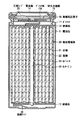
以下、この発明の実施の形態について図面を参照して説明する。図1は、この発明の一実施形態による非水電解液電池の断面構造を示す。この電池は、例えば非水電解液二次電池であり、例えばリチウムイオン二次電池である。 Embodiments of the present invention will be described below with reference to the drawings. FIG. 1 shows a cross-sectional structure of a nonaqueous electrolyte battery according to an embodiment of the present invention. This battery is, for example, a non-aqueous electrolyte secondary battery, for example, a lithium ion secondary battery.
図1に示すように、この二次電池は、いわゆる円筒型といわれるものであり、ほぼ中空円柱状の電池缶11の内部に、帯状の正極21と帯状の負極22とがセパレータ23を介して巻回された巻回電極体20を有している。電池缶11は、例えばニッケル(Ni)のめっきがされた鉄(Fe)により構成されており、一端部が閉鎖され他端部が開放されている。電池缶11の内部には、巻回電極体20を挟むように巻回周面に対して垂直に一対の絶縁板12,13がそれぞれ配置されている。
As shown in FIG. 1, this secondary battery is a so-called cylindrical type, and a strip-shaped
電池缶11の開放端部には、電池蓋14と、この電池蓋14の内側に設けられた安全弁機構15および熱感抵抗素子(Positive Temperature Coefficient;PTC素子)16とが、ガスケット17を介してかしめられることにより取り付けられており、電池缶11の内部は密閉されている。電池蓋14は、例えば、電池缶11と同様の材料により構成されている。
At the open end of the battery can 11, a
安全弁機構15は、熱感抵抗素子16を介して電池蓋14と電気的に接続されており、内部短絡あるいは外部からの加熱などにより電池の内圧が一定以上となった場合にディスク板15Aが反転して電池蓋14と巻回電極体20との電気的接続を切断するようになっている。熱感抵抗素子16は、温度が上昇すると抵抗値の増大により電流を制限し、大電流による異常な発熱を防止するものである。ガスケット17は、例えば、絶縁材料により構成されており、表面にはアスファルトが塗布されている。
The safety valve mechanism 15 is electrically connected to the
巻回電極体20は、例えば、センターピン24を中心に巻回されている。巻回電極体20の正極21にはアルミニウム(Al)などよりなる正極リード25が接続されており、負極22にはニッケル(Ni)などよりなる負極リード26が接続されている。正極リード25は安全弁機構15に溶接されることにより電池蓋14と電気的に接続されており、負極リード26は電池缶11に溶接され電気的に接続されている。
The
図2は図1に示した巻回電極体20の一部を拡大して表すものである。正極21は、例えば、対向する一対の面を有する正極集電体21Aと、正極集電体21Aの両面に設けられた正極活物質層21Bとを有している。なお、正極集電体21Aの片面のみに正極活物質層21Bが存在する領域を有するようにしてもよい。正極集電体21Aは、例えば、アルミニウム(Al)箔などの金属箔により構成されている。
FIG. 2 shows an enlarged part of the spirally
正極活物質層21Bは、例えば、正極活物質を含んでおり、必要に応じてカーボンブラックやグラファイトなどの導電剤と、ポリフッ化ビニリデンなどの結着剤とを含んでいてもよい。正極活物質としては、例えば、オリビン構造を有するリチウムリン酸化合物を用いる。 The positive electrode active material layer 21B includes, for example, a positive electrode active material, and may include a conductive agent such as carbon black or graphite and a binder such as polyvinylidene fluoride as necessary. As the positive electrode active material, for example, a lithium phosphate compound having an olivine structure is used.
オリビン構造を有するリチウムリン酸化合物としては、例えば、化Iで表される化合物を挙げることができる。
(化I)
LiFe1-yMyPO4
(式中、Mはマンガン(Mn)、コバルト(Co)、ニッケル(Ni)、マグネシウム(Mg)、亜鉛(Zn)、クロム(Cr)、チタン(Ti)、バナジウム(V)よりなる群から選ばれる少なくとも1種である。yは0≦y≦0.8である。)
Examples of the lithium phosphate compound having an olivine structure include a compound represented by Formula I.
(Chemical I)
LiFe 1-y M y PO 4
Wherein M is selected from the group consisting of manganese (Mn), cobalt (Co), nickel (Ni), magnesium (Mg), zinc (Zn), chromium (Cr), titanium (Ti), and vanadium (V). Y is 0 ≦ y ≦ 0.8.)
負極22は、例えば、対向する一対の面を有する負極集電体22Aと、負極集電体22Aの両面に設けられた負極活物質層22Bとを有している。なお、負極集電体22Aの片面のみに負極活物質層22Bが存在する領域を有するようにしてもよい。負極集電体22Aは、例えば銅(Cu)箔などの金属箔により構成されている。
The
負極活物質層22Bは、リチウムをドープおよび脱ドープ可能な負極活物質を含んでおり、必要に応じてポリフッ化ビニリデンなどの結着剤を含んでいてもよい。
The negative electrode
負極活物質は、満充電状態にて7LiのNMR(Nuclear magnetic resonance)を測定した場合に塩化リチウム基準の化学シフト値が0ppmから100ppmの範囲に複数のピークに起因するスペクトルを有し、ピーク分離した際にピーク位置が少なくとも1ppm、31ppm、44ppmおよび58ppmに存在する炭素材料を含むものである。 The negative electrode active material has a spectrum caused by a plurality of peaks in the range of 0 to 100 ppm in chemical shift value based on lithium chloride when 7 Li NMR (Nuclear magnetic resonance) is measured in a fully charged state. It includes carbon materials having peak positions at least 1 ppm, 31 ppm, 44 ppm and 58 ppm when separated.
この炭素材料は、例えば、コールタールピッチなどの有機材料を高温熱処理し、粉砕・分級することにより得られる。高温熱処理は、例えば、アルゴンガスなどの不活性ガス雰囲気において、1800℃〜2400℃の範囲で、適宜の時間で保持することにより行われる。 This carbon material can be obtained, for example, by subjecting an organic material such as coal tar pitch to high-temperature heat treatment, pulverization and classification. The high-temperature heat treatment is performed, for example, by maintaining the temperature in the range of 1800 ° C. to 2400 ° C. for an appropriate time in an inert gas atmosphere such as argon gas.
負極活物質は、上記炭素材料と物性の異なる他の炭素材料を含むものであってもよい。その際の上記炭素材料の含有量は、サイクル特性を改善する効果と直流抵抗を低減する効果を勘案すると、負極活物質層22Bに対して、7wt%〜50wt%の範囲内が好ましい。物性の異なる他の炭素材料は、例えば、コールタールピッチなどの有機材料を不活性ガス雰囲気下、1800℃未満または2400℃より高い温度で熱処理し、粉砕・分級して得ることが可能である。
The negative electrode active material may include other carbon materials having different physical properties from the carbon material. The content of the carbon material at that time is preferably in the range of 7 wt% to 50 wt% with respect to the negative electrode
セパレータ23としては、例えば、ポリエチレン多孔質フィルム、ポリプロピレン多孔質フィルム、合成樹脂製不織布などを用いることができる。セパレータ23には、液状の電解質である電解液が含浸されている。 As the separator 23, for example, a polyethylene porous film, a polypropylene porous film, a synthetic resin nonwoven fabric, or the like can be used. The separator 23 is impregnated with an electrolytic solution that is a liquid electrolyte.
電解液は、液状の溶媒、例えば有機溶媒などの非水溶媒と、この非水溶媒に溶解された電解質塩とを含むものである。 The electrolytic solution includes a liquid solvent, for example, a nonaqueous solvent such as an organic solvent, and an electrolyte salt dissolved in the nonaqueous solvent.
非水溶媒は、例えば、エチレンカーボネートおよびプロピレンカーボネートなどの環状炭酸エステルのうちの少なくとも1種を含んでいることが好ましい。サイクル特性を向上させることができるからである。特に、エチレンカーボネートと、プロピレンカーボネートとを混合して含むようにすれば、よりサイクル特性を向上させることができるので好ましい。 The non-aqueous solvent preferably contains at least one of cyclic carbonates such as ethylene carbonate and propylene carbonate. This is because the cycle characteristics can be improved. In particular, it is preferable to mix and contain ethylene carbonate and propylene carbonate because cycle characteristics can be further improved.
非水溶媒は、また、ジエチルカーボネート、ジメチルカーボネート、エチルメチルカーボネートあるいはメチルプロピルカーボネートなどの鎖状炭酸エステルのうちの少なくとも1種を含んでいることが好ましい。サイクル特性をより向上させることができるからである。 The non-aqueous solvent preferably contains at least one of chain carbonates such as diethyl carbonate, dimethyl carbonate, ethyl methyl carbonate, and methyl propyl carbonate. This is because the cycle characteristics can be further improved.
非水溶媒は、さらに、2,4−ジフルオロアニソールおよびビニレンカーボネートのうちの少なくとも一方を含んでいることが好ましい。2,4−ジフルオロアニソールは放電容量を改善することができ、ビニレンカーボネートはサイクル特性をより向上させることができるからである。特に、これらを混合して含んでいれば、放電容量およびサイクル特性を共に向上させることができるのでより好ましい。 The non-aqueous solvent preferably further contains at least one of 2,4-difluoroanisole and vinylene carbonate. This is because 2,4-difluoroanisole can improve discharge capacity, and vinylene carbonate can further improve cycle characteristics. In particular, it is more preferable that they are mixed and contained because both the discharge capacity and the cycle characteristics can be improved.
非水溶媒は、さらに、ブチレンカーボネート、γ−ブチロラクトン、γ−バレロラクトン、これら化合物の水素基の一部または全部をフッ素基で置換したもの、1,2−ジメトキシエタン、テトラヒドロフラン、2−メチルテトラヒドロフラン、1,3−ジオキソラン、4−メチル−1,3−ジオキソラン、酢酸メチル、プロピオン酸メチル、アセトニトリル、グルタロニトリル、アジポニトリル、メトキシアセトニトリル、3−メトキシプロピロニトリル、N,N−ジメチルフォルムアミド、N−メチルピロリジノン、N−メチルオキサゾリジノン、N,N−ジメチルイミダゾリジノン、ニトロメタン、ニトロエタン、スルホラン、ジメチルスルフォキシドあるいはリン酸トリメチルなどのいずれか1種または2種以上を含んでいてもよい。 Nonaqueous solvents further include butylene carbonate, γ-butyrolactone, γ-valerolactone, those in which part or all of the hydrogen groups of these compounds are substituted with fluorine groups, 1,2-dimethoxyethane, tetrahydrofuran, 2-methyltetrahydrofuran. 1,3-dioxolane, 4-methyl-1,3-dioxolane, methyl acetate, methyl propionate, acetonitrile, glutaronitrile, adiponitrile, methoxyacetonitrile, 3-methoxypropyronitrile, N, N-dimethylformamide, N-methylpyrrolidinone, N-methyloxazolidinone, N, N-dimethylimidazolidinone, nitromethane, nitroethane, sulfolane, dimethyl sulfoxide, or trimethyl phosphate may be included.
組み合わせる電極によっては、上記非水溶媒群に含まれる物質の水素原子の一部または全部をフッ素原子で置換したものを用いることにより、電極反応の可逆性が向上する場合がある。したがって、これらの物質を適宜用いることも可能である。 Depending on the electrode to be combined, the reversibility of the electrode reaction may be improved by using a material in which part or all of the hydrogen atoms of the substance contained in the non-aqueous solvent group are substituted with fluorine atoms. Therefore, these substances can be used as appropriate.
電解質塩としては、リチウム塩を用いることができる。リチウム塩としては、例えば、LiPF6、LiBF4、LiAsF6、LiSbF6、LiClO4、LiB(C6H5)4、LiCH3SO3、LiCF3SO3、LiN(SO2CF3)2、LiC(SO2CF3)3、LiAlCl4、LiSiF6、LiCl、LiBF2(ox)〔リチウムジフルオロオキサレートボレート〕、LiBOB(リチウムビスオキサレートボレート)、LiBrなどが適当であり、これらのうちのいずれか1種をまたは2種以上を混合して、用いる。なかでも、LiPF6は、高いイオン伝導性を得ることができるとともに、サイクル特性を向上させることができるので好ましい。 A lithium salt can be used as the electrolyte salt. Examples of the lithium salt include LiPF 6 , LiBF 4 , LiAsF 6 , LiSbF 6 , LiClO 4 , LiB (C 6 H 5 ) 4 , LiCH 3 SO 3 , LiCF 3 SO 3 , LiN (SO 2 CF 3 ) 2 , LiC (SO 2 CF 3 ) 3 , LiAlCl 4 , LiSiF 6 , LiCl, LiBF 2 (ox) [lithium difluorooxalate borate], LiBOB (lithium bisoxalate borate), LiBr, etc. are suitable, and among these, Any one kind or a mixture of two or more kinds is used. Among them, LiPF 6 is preferable because it can obtain high ion conductivity and can improve cycle characteristics.
この二次電池は、例えば以下に説明するようにして、製造することができる。まず、例えば、正極活物質と、導電剤と、結着剤とを混合して正極合剤を調製し、この正極合剤をN−メチルピロリドンなどの溶剤に分散させて正極合剤スラリーとする。続いて、この正極合剤スラリーを正極集電体21Aに塗布し溶剤を乾燥させたのち、ロールプレス機などにより圧縮成型して正極活物質層21Bを形成し、正極21を作製する。
This secondary battery can be manufactured, for example, as described below. First, for example, a positive electrode active material, a conductive agent, and a binder are mixed to prepare a positive electrode mixture, and the positive electrode mixture is dispersed in a solvent such as N-methylpyrrolidone to obtain a positive electrode mixture slurry. . Subsequently, the positive electrode mixture slurry is applied to the positive electrode
また、例えば、負極活物質と、結着剤とを混合して負極合剤を調製し、この負極合剤をN−メチルピロリドンなどの溶剤に分散させて負極合剤スラリーとする。続いて、この負極合剤スラリーを負極集電体22Aに塗布し溶剤を乾燥させたのち、ロールプレス機などにより圧縮成型して負極活物質層22Bを形成し、負極22を作製する。
Further, for example, a negative electrode active material and a binder are mixed to prepare a negative electrode mixture, and the negative electrode mixture is dispersed in a solvent such as N-methylpyrrolidone to obtain a negative electrode mixture slurry. Subsequently, the negative electrode mixture slurry is applied to the negative electrode
次いで、正極集電体21に正極リード25を溶接などにより取り付けるとともに、負極集電体22に負極リード26を溶接などにより取り付ける。そののち、正極21と負極22とをセパレータ23を介して巻回し、正極リード25の先端部を安全弁機構15に溶接すると共に、負極リード26の先端部を電池缶11に溶接して、巻回した正極21および負極22を一対の絶縁板12,13で挟み電池缶11の内部に収納する。
Next, the
正極21および負極22を電池缶11の内部に収納したのち、上述した電解液を電池缶11の内部に注入し、セパレータ23に含浸させる。そののち、電池缶11の開口端部に電池蓋14、安全弁機構15および熱感抵抗素子16を、ガスケット17を介してかしめることにより固定する。以上により、図1に示した二次電池を製造できる。
After the
この二次電池では、充電を行うと、例えば、正極21からリチウムイオンが離脱し、電解液を介して負極22に吸蔵される。放電を行うと、例えば、負極22からリチウムイオンが離脱し、電解液を介して正極21に吸蔵される。
In this secondary battery, when charged, for example, lithium ions are released from the
この発明の具体的な実施例について詳細に説明する。ただし、この発明はこれらの実施例に限定されるものではない。 Specific embodiments of the present invention will be described in detail. However, the present invention is not limited to these examples.
<実施例1> <Example 1>
[炭素材料(I)の作製]
コールタールピッチを不活性ガス雰囲気下で1900℃にて加熱処理し、炭素材料(I)を得た。
[Production of carbon material (I)]
The coal tar pitch was heat-treated at 1900 ° C. in an inert gas atmosphere to obtain a carbon material (I).
[円筒セルの作製]
炭素材料(I)92質量部とポリフッ化ビニリデン8質量部と、分量外のN−メチル−2−ピロリドンとを混練し、負極合剤塗料を得た。この負極合剤塗料を、厚さ15μmの銅箔の両面に塗布し、乾燥後、プレスして帯状の負極電極を作製した。
[Production of cylindrical cell]
92 parts by mass of carbon material (I), 8 parts by mass of polyvinylidene fluoride, and N-methyl-2-pyrrolidone out of the quantity were kneaded to obtain a negative electrode mixture paint. This negative electrode mixture paint was applied to both sides of a copper foil having a thickness of 15 μm, dried and pressed to prepare a strip-like negative electrode.
LiCO3と、FeSO4・7H2Oと、NH4H2PO4とを所定量混合し、さらに前記混合粉とカーボンブラックとを97:3の重量比となるように混合した後、ボールミルにて乾式混合を10時間行った。この混合粉を窒素雰囲気下にて550℃焼成を行い、カーボンを被覆したLiFePO4で表されたオリビン構造を有するリチウムリン酸化合物を得た。 A predetermined amount of LiCO 3 , FeSO 4 .7H 2 O, and NH 4 H 2 PO 4 is mixed, and the mixed powder and carbon black are mixed at a weight ratio of 97: 3. And dry mixing for 10 hours. The mixed powder was baked at 550 ° C. in a nitrogen atmosphere to obtain a lithium phosphate compound having an olivine structure represented by LiFePO 4 coated with carbon.
このリチウムリン酸化合物85質量部と、ポリフッ化ビニリデン10質量部と、人造黒鉛5質量部と、分量外のN−メチル−2−ピロリドンとを混練し、正極合剤塗料を得た。この正極合剤塗料を厚さ15μmのアルミニウム箔の両面に塗布し、乾燥後、プレスして帯状の正極電極を作製した。 85 parts by mass of this lithium phosphate compound, 10 parts by mass of polyvinylidene fluoride, 5 parts by mass of artificial graphite, and N-methyl-2-pyrrolidone outside the amount were kneaded to obtain a positive electrode mixture paint. This positive electrode mixture paint was applied to both sides of an aluminum foil having a thickness of 15 μm, dried and pressed to produce a strip-like positive electrode.
正極電極と負極電極との間に厚さ25μmのポリプロピレン製微孔フィルムをはさんで巻回し、エチレンカーボネートとジメチルカーボネートとを等容量で混合した混合溶媒にLiPF61mol/lを溶解させた非水電解液とともに直径18mm、高さ65mmの金属ケースに入れ、容量が1Ahの18650サイズの実施例1の円筒セルを作製した。 A polypropylene microporous film having a thickness of 25 μm was wound between the positive electrode and the negative electrode, and LiPF 6 1 mol / l was dissolved in a mixed solvent in which ethylene carbonate and dimethyl carbonate were mixed in an equal volume. A cylindrical cell of Example 1 having a capacity of 1 Ah and 18650 size was prepared together with a water electrolyte in a metal case having a diameter of 18 mm and a height of 65 mm.
<実施例2>
[炭素材料(II)の作製]
コールタールピッチを不活性ガス雰囲気下で2800℃にて加熱処理し、炭素材料(II)を得た。
<Example 2>
[Production of carbon material (II)]
The coal tar pitch was heat-treated at 2800 ° C. in an inert gas atmosphere to obtain a carbon material (II).
[円筒セルの作製]
炭素材料(I)7質量部と、炭素材料(II)85質量部と、ポリフッ化ビニリデン8質量部と、分量外のN−メチル−2−ピロリドンとを混練し、負極合剤塗料を得た。以上の点以外は、実施例1と同様にして、実施例2の円筒セルを作製した。
[Production of cylindrical cell]
7 parts by mass of carbon material (I), 85 parts by mass of carbon material (II), 8 parts by mass of polyvinylidene fluoride, and N-methyl-2-pyrrolidone out of the quantity were kneaded to obtain a negative electrode mixture paint. . Except for the above, a cylindrical cell of Example 2 was produced in the same manner as Example 1.
<実施例3>
[円筒セルの作製]
炭素材料(I)42質量部と、炭素材料(II)50質量部と、ポリフッ化ビニリデン8質量部と、分量外のN−メチル−2−ピロリドンとを混練し、負極合剤塗料を得た。以上の点以外は、実施例1と同様にして、実施例3の円筒セルを作製した。
<Example 3>
[Production of cylindrical cell]
42 parts by mass of carbon material (I), 50 parts by mass of carbon material (II), 8 parts by mass of polyvinylidene fluoride, and N-methyl-2-pyrrolidone out of the quantity were kneaded to obtain a negative electrode mixture paint. . Except for the above, a cylindrical cell of Example 3 was produced in the same manner as Example 1.
<実施例4>
[円筒セルの作製]
炭素材料(I)52質量部と、炭素材料(II)40質量部と、ポリフッ化ビニリデン8質量部と、分量外のN−メチル−2−ピロリドンとを混練し、負極合剤塗料を得た点以外は、実施例1と同様にして、実施例4の円筒セルを作製した。
<Example 4>
[Production of cylindrical cell]
52 parts by mass of carbon material (I), 40 parts by mass of carbon material (II), 8 parts by mass of polyvinylidene fluoride, and N-methyl-2-pyrrolidone out of the quantity were kneaded to obtain a negative electrode mixture paint. A cylindrical cell of Example 4 was produced in the same manner as Example 1 except for the points.
<実施例5>
[円筒セルの作製]
炭素材料(I)5質量部と、炭素材料(II)87質量部と、ポリフッ化ビニリデン5質量部と、分量外のN−メチル−2−ピロリドンとを混練し、負極合剤塗料を得た。以上の点以外は、実施例1と同様にして、実施例5の円筒セルを作製した。
<Example 5>
[Production of cylindrical cell]
5 parts by mass of carbon material (I), 87 parts by mass of carbon material (II), 5 parts by mass of polyvinylidene fluoride, and N-methyl-2-pyrrolidone outside the amount were kneaded to obtain a negative electrode mixture paint. . Except for the above, a cylindrical cell of Example 5 was produced in the same manner as Example 1.
<実施例6>
[円筒セルの作製]
Li2Co3と、MnCO3と、FeSO4・7H2Oと、NH4H2PO4とを所定量混合し、さらに前記混合粉とカーボンブラックとを97:3の重量比となるように混合した後、ボールミルにて乾式混合を10時間行った。この混合粉を窒素雰囲気下にて550℃焼成を行い、LiMn0.7Fe0.3PO4で表されるMnFeオリビン正極活物質材料を得た。このMnFeオリビン正極活物質材料85質量部と、ポリフッ化ビニリデン10質量部と、人造黒鉛5質量部と、分量外のN−メチル−2−ピロリドンとを混練し、正極合剤塗料を得た。以上の点以外は、実施例1と同様にして、実施例6の円筒セルを作製した。
<Example 6>
[Production of cylindrical cell]
A predetermined amount of Li 2 Co 3 , MnCO 3 , FeSO 4 .7H 2 O and NH 4 H 2 PO 4 is mixed, and the mixed powder and carbon black are mixed at a weight ratio of 97: 3. After mixing, dry mixing was performed for 10 hours in a ball mill. This mixed powder was baked at 550 ° C. in a nitrogen atmosphere to obtain a MnFe olivine positive electrode active material represented by LiMn 0.7 Fe 0.3 PO 4 . 85 parts by mass of this MnFe olivine positive electrode active material, 10 parts by mass of polyvinylidene fluoride, 5 parts by mass of artificial graphite, and N-methyl-2-pyrrolidone out of the amount were kneaded to obtain a positive electrode mixture paint. Except for the above, a cylindrical cell of Example 6 was produced in the same manner as Example 1.
<比較例1>
[円筒セルの作製]
炭素材料(II)92質量部と、ポリフッ化ビニリデン8質量部と、分量外のN−メチル−2−ピロリドンとを混練し、負極合剤塗料を得た。以上の点以外は、実施例1と同様にして、比較例1の円筒セルを作製した。
<比較例2>
[円筒セルの作製]
コバルト酸リチウム85質量部と、ポリフッ化ビニリデン10質量部と、人造黒鉛5質量部と、分量外のN−メチル−2−ピロリドンとを混練し、正極合剤塗料を得た。以上の点以外は、比較例1と同様にして、比較例2の円筒セルを作製した。
<Comparative Example 1>
[Production of cylindrical cell]
92 parts by mass of carbon material (II), 8 parts by mass of polyvinylidene fluoride, and N-methyl-2-pyrrolidone out of the quantity were kneaded to obtain a negative electrode mixture paint. Except for the above, a cylindrical cell of Comparative Example 1 was produced in the same manner as Example 1.
<Comparative example 2>
[Production of cylindrical cell]
85 parts by mass of lithium cobaltate, 10 parts by mass of polyvinylidene fluoride, 5 parts by mass of artificial graphite, and N-methyl-2-pyrrolidone outside the quantity were kneaded to obtain a positive electrode mixture paint. Except for the above, a cylindrical cell of Comparative Example 2 was produced in the same manner as Comparative Example 1.
<比較例3>
コバルト酸リチウム85質量部と、ポリフッ化ビニリデン10質量部と、人造黒鉛5質量部と、分量外のN−メチル−2−ピロリドンとを混練し、正極合剤塗料を得た。以上の点以外は、実施例1と同様にして、比較例3の円筒セルを作製した。
<Comparative Example 3>
85 parts by mass of lithium cobaltate, 10 parts by mass of polyvinylidene fluoride, 5 parts by mass of artificial graphite, and N-methyl-2-pyrrolidone outside the quantity were kneaded to obtain a positive electrode mixture paint. Except for the above, a cylindrical cell of Comparative Example 3 was produced in the same manner as Example 1.
<比較例4>
[円筒セルの作製]
炭素材料(II)92質量部と、ポリフッ化ビニリデン8質量部と、分量外のN−メチル−2−ピロリドンとを混練し、負極合剤塗料を得た。以上の点以外は、実施例6と同様にして、比較例4の円筒セルを作製した。
<Comparative example 4>
[Production of cylindrical cell]
92 parts by mass of carbon material (II), 8 parts by mass of polyvinylidene fluoride, and N-methyl-2-pyrrolidone out of the quantity were kneaded to obtain a negative electrode mixture paint. Except for the above, a cylindrical cell of Comparative Example 4 was produced in the same manner as in Example 6.
(評価)
実施例1〜実施例6および比較例1〜比較例4について、以下に説明する(I)〜(IV)の評価を行った。
(Evaluation)
For Examples 1 to 6 and Comparative Examples 1 to 4, the following (I) to (IV) were evaluated.
(I)満充電状態での7Li−NMR測定
炭素材料(I)92質量部と、ポリフッ化ビニリデン8質量部と、分量外のN−メチル−2−ピロリドンとを混練し、実施例1と同様の負極合剤塗料を得た。この負極合剤塗料を、厚さ15μmの銅箔の片面にのみ塗布した後、乾燥してプレスし、15mmφに打ち抜くことによりコインセル用の電極を作製した。なお、粉体塗布量は、5mg/cm2〜10mg/cm2(片面)であることが望ましいので、粉体塗布量をこの範囲内になるように調整した。
(I) 7 Li-NMR measurement in a fully charged state 92 parts by mass of carbon material (I), 8 parts by mass of polyvinylidene fluoride, and N-methyl-2-pyrrolidone out of the quantity were kneaded, and Example 1 A similar negative electrode mixture paint was obtained. This negative electrode mixture paint was applied only to one side of a 15 μm thick copper foil, dried and pressed, and punched to 15 mmφ to produce a coin cell electrode. Incidentally, the powder coating amount, since it is desirable that the 5mg / cm 2 ~10mg / cm 2 ( one side) was adjusted to the powder coating amount within this range.
作製したコインセル用と対極としてのLi金属との間に、厚さ25μmのポリプロピレン製微多孔フィルムをはさみ、電解液は実施例1と同じ組成のものを用いて、コインセルを作製した。このコインセルを、定電流定電圧充電(0.1C−0V−15h)、放電(0.1C 2V)にて1サイクル充放電した後、再度同じ充電条件にて充電した。 A coin cell was produced using a microporous film made of polypropylene having a thickness of 25 μm sandwiched between the produced coin cell and a Li metal as a counter electrode, and the electrolytic solution having the same composition as in Example 1. The coin cell was charged and discharged for one cycle by constant current and constant voltage charging (0.1C-0V-15h) and discharging (0.1C 2V), and then charged again under the same charging conditions.
この状態でコインセルを解体し、負極電極を取り出し、DMC(ジメチルカーボネート)にて洗浄した後、銅箔から負極粉末を削り落とした後、以下の条件にて7Li−NMR測定を行った。また、比較例1についても、比較例1と同様の負極合剤塗料を用いてコインセルを作製し、同様に7Li−NMR測定を行った。
装置:ブルカー社製 核磁気共鳴装置 AVANCE400 (2.5mm MASプローブを装着)
温度:室温
測定核:7Li
試料回転速度 :30kHz(マジックアングルスピニング法)
基準物質:1M LiCl aq
In this state, the coin cell was disassembled, the negative electrode was taken out, washed with DMC (dimethyl carbonate), the negative electrode powder was scraped off from the copper foil, and 7 Li-NMR measurement was performed under the following conditions. As for Comparative Example 1, to prepare a coin cell using the same negative electrode mixture coating in Comparative Example 1 was subjected to the same 7 Li-NMR measurement.
Equipment: Bruker Nuclear Magnetic Resonance Equipment AVANCE400 (with 2.5mm MAS probe)
Temperature: Room temperature Measurement nucleus: 7 Li
Sample rotation speed: 30 kHz (magic angle spinning method)
Reference material: 1M LiCl aq
7Li−NMR測定によって得られた、炭素材料(I)および炭素材料(II)の7Li−NMRスペクトルを図3に示す。 FIG. 3 shows 7 Li-NMR spectra of the carbon material (I) and the carbon material (II) obtained by 7 Li-NMR measurement.
図3において、実線で示されるのが炭素材料(I)の7Li−NMR測定の測定結果であり、上向き矢印はピーク分離した際のピーク位置を示す。点線で示されるのが炭素材料(II)の7Li−NMR測定結果であり、下向き矢印はピーク位置を示す。 In FIG. 3, the solid line indicates the measurement result of the 7 Li-NMR measurement of the carbon material (I), and the upward arrow indicates the peak position when the peaks are separated. The dotted line indicates the 7 Li-NMR measurement result of the carbon material (II), and the downward arrow indicates the peak position.
図3に示すように、炭素材料(I)の7Li−NMRスペクトルでは、0〜100ppmに4個のピークが確認され、そのピーク位置はそれぞれ1ppm、31ppm、44ppm、58ppmであった。炭素材料(II)の7Li−NMRスペクトルでは、0〜100ppmに2個のピークが確認され、そのピーク位置はそれぞれ5ppm、44ppmであった。 As shown in FIG. 3, in the 7 Li-NMR spectrum of the carbon material (I), 4 peaks were confirmed at 0 to 100 ppm, and the peak positions were 1 ppm, 31 ppm, 44 ppm, and 58 ppm, respectively. In the 7 Li-NMR spectrum of the carbon material (II), two peaks were confirmed at 0 to 100 ppm, and the peak positions were 5 ppm and 44 ppm, respectively.
(II)サイクル特性評価
実施例1〜実施例6および比較例1〜比較例4の円筒セルについて、それぞれ定電流定電圧充電(1A 3.6V 0.1Acut)と、定電流放電(7A 2.0V)とを繰り返す、サイクル試験を行い、1サイクル時の放電容量に対する500サイクル時の放電容量の容量維持率を求め、実施例および比較例それぞれの容量維持率を棒グラフにまとめた。図4に、実施例1〜実施例6および比較例1〜比較例4のサイクル容量維持率をまとめたグラフを示す。
(II) Evaluation of cycle characteristics For the cylindrical cells of Examples 1 to 6 and Comparative Examples 1 to 4, constant current and constant voltage charging (1A 3.6V 0.1 Acut) and constant current discharging (7A 2. 0V) was repeated, and the capacity retention rate of the discharge capacity at 500 cycles with respect to the discharge capacity at 1 cycle was determined, and the capacity retention rates of the examples and comparative examples were summarized in a bar graph. FIG. 4 shows a graph summarizing the cycle capacity retention rates of Examples 1 to 6 and Comparative Examples 1 to 4.
図4に示すように、実施例1〜実施例5では、正極にオリビン構造を有するLiFePO4を用いた場合において、負極に炭素材料(I)を含むので、比較例1より優れたサイクル特性が得られた。 As shown in FIG. 4, in Examples 1 to 5, when LiFePO 4 having an olivine structure is used for the positive electrode, the carbon material (I) is included in the negative electrode. Obtained.
また、正極活物質がLiCoO2である比較例2と比較例3との比較によると、サイクル特性に差異が認められなかった。これはLiFePO4に比べて充電時に定電流領域が短いため、負極違いによるサイクル特性への影響が小さかったものと考えられる。同様に実施例6と比較例4との比較からわかるように、正極活物質として、LiMn0.7Fe0.3PO4を用いた場合にサイクル特性の改善効果があるが、正極活物質として、LiFePO4ほどの改善効果は得られないことがわかった。 Further, according to the comparison between Comparative Example 2 and Comparative Example 3 in which the positive electrode active material was LiCoO 2 , no difference was observed in the cycle characteristics. This is thought to be because the constant current region during charging was shorter than that of LiFePO 4 , so that the influence on the cycle characteristics due to the difference in the negative electrode was small. As can be seen from the comparison between Comparative Example 4 Similarly to Example 6, as the positive electrode active material, there is improvement in the cycle properties when using the LiMn 0.7 Fe 0.3 PO 4, as the positive electrode active material, as LiFePO 4 It was found that no improvement effect was obtained.
(III)負極電極容量比較
実施例1〜実施例5、比較例1で得た負極合剤塗料を用いて、評価(I)と同様にコインセルを作製し、定電流定電圧充電(0.1C−0V−15h)、放電(0.1C 2V)にて1サイクル充放電を行い、0.1C放電容量を測定し、負極活物質重量あたりの放電容量を求めた。
(III) Negative electrode capacity comparison Using the negative electrode mixture paints obtained in Examples 1 to 5 and Comparative Example 1, coin cells were prepared in the same manner as in the evaluation (I), and constant current constant voltage charging (0.1 C -0V-15h), 1 cycle charge / discharge was performed with discharge (0.1C 2V), 0.1C discharge capacity was measured, and the discharge capacity per weight of the negative electrode active material was determined.
(IV)直流抵抗測定
実施例1〜実施例5および比較例1の円筒セルについて、満充電状態の状態から10A放電を行い、1秒後の電圧V1と放電直前の電圧V0を用いて直流抵抗を(式1)により算出した。
直流抵抗=(V0−V1)/10・・・(式1)
(IV) DC resistance measurement For the cylindrical cells of Examples 1 to 5 and Comparative Example 1, 10 A discharge was performed from the fully charged state, and the DC resistance was measured using the voltage V1 after 1 second and the voltage V0 immediately before the discharge. Was calculated by (Equation 1).
DC resistance = (V0−V1) / 10 (Expression 1)
(III)〜(IV)の測定結果を表1に示す。なお、(IV)については、比較例1の直流抵抗値を100%とした場合の比較値をまとめたものである。 The measurement results of (III) to (IV) are shown in Table 1. Note that (IV) is a summary of comparative values when the DC resistance value of Comparative Example 1 is 100%.
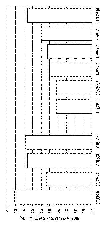
表1に示すように、炭素材料(II)は、黒鉛構造が発達したため、高容量を得られるが、炭素材料(I)は、黒鉛構造が比較的未発達であるため、容量が低いことがわかった。 As shown in Table 1, the carbon material (II) can obtain a high capacity because the graphite structure has developed, but the carbon material (I) has a relatively low capacity because the graphite structure is relatively undeveloped. all right.
また、実施例2〜実施例3および比較例1によると、炭素材料(I)は、炭素材料(II)に比べ、直流抵抗を下げる効果が大きいことがわかった。しかしながら、炭素材料(I)の混合量が多すぎると、負極での容量が低くなり、負極の塗布量を増加させる必要が生じるため、実施例1のように電池の直流抵抗が大きすぎるという弊害が生じてしまう。 Further, according to Examples 2 to 3 and Comparative Example 1, it was found that the carbon material (I) had a greater effect of reducing the direct current resistance than the carbon material (II). However, if the mixing amount of the carbon material (I) is too large, the capacity at the negative electrode becomes low, and it becomes necessary to increase the coating amount of the negative electrode. Therefore, there is an adverse effect that the direct current resistance of the battery is too large as in Example 1. Will occur.
以上、サイクル特性の改善効果と直流抵抗低減の効果から勘案して、負極活物質層に含まれる炭素材料(I)の含有量しては、7wt%以上50wt%以下の範囲内であることが望ましいことがわかった。 As described above, in consideration of the effect of improving the cycle characteristics and the effect of reducing the direct current resistance, the content of the carbon material (I) contained in the negative electrode active material layer is within the range of 7 wt% or more and 50 wt% or less. I found it desirable.
この発明は、上述したこの発明の実施形態に限定されるものでは無く、この発明の要旨を逸脱しない範囲内で様々な変形や応用が可能である。例えば、上述した実施形態では、円筒型電池を例に挙げて説明したが、この発明はこれに限定されるものではなく、例えば角型電池、コイン型電池、ボタン型電池などといった外装材に金属製容器などを用いた電池、薄型電池といった外装材にラミネートフィルムなどを用いた電池など、様々な形状や大きさにすることも可能である。 The present invention is not limited to the above-described embodiments of the present invention, and various modifications and applications are possible without departing from the spirit of the present invention. For example, in the above-described embodiment, a cylindrical battery has been described as an example. However, the present invention is not limited to this, and for example, a metal for an exterior material such as a square battery, a coin battery, a button battery, or the like. Various shapes and sizes, such as a battery using a container or the like, a battery using a laminate film or the like as an exterior material such as a thin battery, can be used.
また、例えば、電解液に代えて、他の電解質、例えば高分子化合物に電解液を保持させたゲル状の電解質を用いてもよい。電解液(すなわち液状の溶媒、電解質塩および添加剤)については上述のとおりであり、高分子化合物としては、例えば、ポリアクリロニトリル、ポリフッ化ビニリデン、ポリフッ化ビニリデンとポリヘキサフルオロプロピレンとの共重合体、ポリテトラフルオロエチレン、ポリヘキサフルオロプロピレン、ポリエチレンオキサイド、ポリプロピレンオキサイド、ポリフォスファゼン、ポリシロキサン、ポリ酢酸ビニル、ポリビニルアルコール、ポリメタクリル酸メチル、ポリアクリル酸、ポリメタクリル酸、スチレン−ブタジエンゴム、ニトリル−ブタジエンゴム、ポリスチレン、ポリカーボネートが挙げられる。特に電気化学的な安定性を考慮すると、ポリアクリロニトリル、ポリフッ化ビニリデン、ポリヘキサフルオロプロピレン、ポリエチレンオキサイドなどが好ましい。 For example, instead of the electrolytic solution, another electrolyte, for example, a gel electrolyte in which the electrolytic solution is held in a polymer compound may be used. The electrolyte solution (that is, liquid solvent, electrolyte salt, and additive) is as described above. Examples of the polymer compound include polyacrylonitrile, polyvinylidene fluoride, and a copolymer of polyvinylidene fluoride and polyhexafluoropropylene. , Polytetrafluoroethylene, polyhexafluoropropylene, polyethylene oxide, polypropylene oxide, polyphosphazene, polysiloxane, polyvinyl acetate, polyvinyl alcohol, polymethyl methacrylate, polyacrylic acid, polymethacrylic acid, styrene-butadiene rubber, nitrile -Butadiene rubber, polystyrene, polycarbonate. In particular, in consideration of electrochemical stability, polyacrylonitrile, polyvinylidene fluoride, polyhexafluoropropylene, polyethylene oxide, and the like are preferable.
また、他の電解質としては、イオン伝導性高分子を利用した高分子固体電解質、またはイオン伝導性無機材料を利用した無機固体電解質なども挙げられ、これらを単独あるいは他の電解質と組み合わせて用いてもよい。高分子固体電解質に用いることができる高分子化合物としては、ポリエーテル、ポリエステル、ポリフォスファゼン、あるいはポリシロキサンなどが挙げられる。無機固体電解質としては、イオン伝導性セラミックス、イオン伝導性結晶、あるいはイオン伝導性ガラスなどが挙げられる Examples of other electrolytes include solid polymer electrolytes using ion conductive polymers, and inorganic solid electrolytes using ion conductive inorganic materials. These can be used alone or in combination with other electrolytes. Also good. Examples of the polymer compound that can be used for the polymer solid electrolyte include polyether, polyester, polyphosphazene, and polysiloxane. Examples of the inorganic solid electrolyte include ion conductive ceramics, ion conductive crystals, and ion conductive glass.
11・・・電池缶
12,13・・・絶縁板
14・・・電池蓋
15・・・安全弁機構
16・・・熱抵抗素子
17・・・ガスケット
20・・・巻回電極体
21・・・正極
21A・・・正極集電体
21B・・・正極活物質層
22・・・負極
22A・・・負極集電体
22B・・・負極活物質層
23・・・セパレータ
24・・・センターピン
25・・・正極リード
26・・・負極リード
DESCRIPTION OF SYMBOLS 11 ... Battery can 12, 13 ... Insulating
Claims (3)
上記負極活物質は、満充電状態にて7LiのNMRを測定した場合に塩化リチウム基準の化学シフト値が0ppmから100ppmの範囲に複数のピークに起因するスペクトルを有し、且つピーク分離した際にピーク位置が少なくとも1ppm、31ppm、44ppmおよび58ppmに存在する炭素材料を含むこと
を特徴とする非水電解質電池。 A positive electrode including a lithium phosphate compound having an olivine structure, a negative electrode including a negative electrode active material capable of doping and dedoping lithium, and a non-aqueous electrolyte,
The negative electrode active material has a spectrum derived from a plurality of peaks in the range of 0 to 100 ppm in terms of the chemical shift value based on lithium chloride when 7 Li NMR is measured in a fully charged state, and when the peak is separated And a carbon material having a peak position of at least 1 ppm, 31 ppm, 44 ppm and 58 ppm.
を特徴とする請求項1記載の非水電解質電池。 The nonaqueous electrolyte battery according to claim 1, wherein the content of the carbon material contained in the negative electrode active material layer is within a range of 7 wt% to 50 wt%.
を特徴とする請求項1記載の非水電解質電池。 The nonaqueous electrolyte battery according to claim 1, wherein the lithium phosphate compound having an olivine structure is a compound represented by LiFePO 4 .
Priority Applications (1)
| Application Number | Priority Date | Filing Date | Title |
|---|---|---|---|
| JP2007295302A JP2009123473A (en) | 2007-11-14 | 2007-11-14 | Nonaqueous electrolyte battery |
Applications Claiming Priority (1)
| Application Number | Priority Date | Filing Date | Title |
|---|---|---|---|
| JP2007295302A JP2009123473A (en) | 2007-11-14 | 2007-11-14 | Nonaqueous electrolyte battery |
Publications (1)
| Publication Number | Publication Date |
|---|---|
| JP2009123473A true JP2009123473A (en) | 2009-06-04 |
Family
ID=40815419
Family Applications (1)
| Application Number | Title | Priority Date | Filing Date |
|---|---|---|---|
| JP2007295302A Pending JP2009123473A (en) | 2007-11-14 | 2007-11-14 | Nonaqueous electrolyte battery |
Country Status (1)
| Country | Link |
|---|---|
| JP (1) | JP2009123473A (en) |
Citations (6)
| Publication number | Priority date | Publication date | Assignee | Title |
|---|---|---|---|---|
| JPH05121066A (en) * | 1991-10-29 | 1993-05-18 | Asahi Chem Ind Co Ltd | Negative electrode for nonaqueous battery |
| WO1998024134A1 (en) * | 1996-11-26 | 1998-06-04 | Kao Corporation | Negative electrode material for nonaqueous secondary battery |
| JPH11167920A (en) * | 1997-12-05 | 1999-06-22 | Kansai Coke & Chem Co Ltd | Manufacture of negative electrode material for nonaqueous secondary battery |
| JP2005108681A (en) * | 2003-09-30 | 2005-04-21 | Mitsubishi Chemicals Corp | Material for positive electrode of lithium secondary battery, positive electrode of lithium secondary battery and lithium secondary battery |
| JP2006310265A (en) * | 2005-03-31 | 2006-11-09 | Mitsubishi Chemicals Corp | Negative electrode material for non-aqueous electrolytic liquid secondary battery and non-aqueous electrolytic liquid secondary battery using it |
| JP2007294323A (en) * | 2006-04-26 | 2007-11-08 | Gs Yuasa Corporation:Kk | Method for manufacturing nonaqueous electrolytic solution battery |
-
2007
- 2007-11-14 JP JP2007295302A patent/JP2009123473A/en active Pending
Patent Citations (6)
| Publication number | Priority date | Publication date | Assignee | Title |
|---|---|---|---|---|
| JPH05121066A (en) * | 1991-10-29 | 1993-05-18 | Asahi Chem Ind Co Ltd | Negative electrode for nonaqueous battery |
| WO1998024134A1 (en) * | 1996-11-26 | 1998-06-04 | Kao Corporation | Negative electrode material for nonaqueous secondary battery |
| JPH11167920A (en) * | 1997-12-05 | 1999-06-22 | Kansai Coke & Chem Co Ltd | Manufacture of negative electrode material for nonaqueous secondary battery |
| JP2005108681A (en) * | 2003-09-30 | 2005-04-21 | Mitsubishi Chemicals Corp | Material for positive electrode of lithium secondary battery, positive electrode of lithium secondary battery and lithium secondary battery |
| JP2006310265A (en) * | 2005-03-31 | 2006-11-09 | Mitsubishi Chemicals Corp | Negative electrode material for non-aqueous electrolytic liquid secondary battery and non-aqueous electrolytic liquid secondary battery using it |
| JP2007294323A (en) * | 2006-04-26 | 2007-11-08 | Gs Yuasa Corporation:Kk | Method for manufacturing nonaqueous electrolytic solution battery |
Similar Documents
| Publication | Publication Date | Title |
|---|---|---|
| US6884546B1 (en) | Secondary battery | |
| JP5070753B2 (en) | battery | |
| JP5910627B2 (en) | Secondary battery | |
| JP5262175B2 (en) | Negative electrode and secondary battery | |
| CN109216758B (en) | Nonaqueous electrolyte battery and method for manufacturing nonaqueous electrolyte battery | |
| JP2008059999A (en) | Negative electrode and nonaqueous electrolyte secondary battery using it | |
| US10044072B2 (en) | Lithium secondary battery pack, as well as electronic device, charging system, and charging method using said pack | |
| JP4968225B2 (en) | Non-aqueous electrolyte battery | |
| JP5412843B2 (en) | battery | |
| JP2009123474A (en) | Nonaqueous electrolyte battery | |
| US20140227562A1 (en) | Lithium secondary-battery pack, electronic device using same, charging system, and charging method | |
| KR20160091864A (en) | Nonaqueous electrolyte secondary battery | |
| JP2009134970A (en) | Nonaqueous electrolytic battery | |
| JP4715848B2 (en) | battery | |
| US20190131623A1 (en) | Method for charging lithium-ion secondary battery, lithium-ion secondary battery system, and power storage device | |
| JP4424895B2 (en) | Lithium secondary battery | |
| KR101521646B1 (en) | Secondary battery with high capacity and longevity comprising silazane-based compound | |
| JP4560854B2 (en) | Nonaqueous electrolyte secondary battery | |
| JP2009048815A (en) | Nonaqueous electrolyte solution secondary battery | |
| US8372541B2 (en) | Non-aqueous electrolyte secondary battery | |
| JP2007157538A (en) | Battery | |
| JP2010135115A (en) | Nonaqueous electrolyte secondary battery | |
| JP2002117903A (en) | Nonaqueous electrolyte battery | |
| JP4938923B2 (en) | Secondary battery | |
| KR101551593B1 (en) | Secondary battery with high capacity and longevity comprising silazane-based compound |
Legal Events
| Date | Code | Title | Description |
|---|---|---|---|
| A621 | Written request for application examination |
Free format text: JAPANESE INTERMEDIATE CODE: A621 Effective date: 20100812 |
|
| A977 | Report on retrieval |
Free format text: JAPANESE INTERMEDIATE CODE: A971007 Effective date: 20120822 |
|
| A131 | Notification of reasons for refusal |
Free format text: JAPANESE INTERMEDIATE CODE: A131 Effective date: 20120828 |
|
| A02 | Decision of refusal |
Free format text: JAPANESE INTERMEDIATE CODE: A02 Effective date: 20130312 |