JP2009123193A - Portable terminal - Google Patents
Portable terminal Download PDFInfo
- Publication number
- JP2009123193A JP2009123193A JP2008215890A JP2008215890A JP2009123193A JP 2009123193 A JP2009123193 A JP 2009123193A JP 2008215890 A JP2008215890 A JP 2008215890A JP 2008215890 A JP2008215890 A JP 2008215890A JP 2009123193 A JP2009123193 A JP 2009123193A
- Authority
- JP
- Japan
- Prior art keywords
- touch
- sheet
- region
- mobile terminal
- area
- Prior art date
- Legal status (The legal status is an assumption and is not a legal conclusion. Google has not performed a legal analysis and makes no representation as to the accuracy of the status listed.)
- Granted
Links
- 238000000034 method Methods 0.000 claims description 23
- 238000005286 illumination Methods 0.000 claims description 13
- 230000008859 change Effects 0.000 claims description 9
- 239000011159 matrix material Substances 0.000 claims description 7
- 239000000463 material Substances 0.000 claims description 6
- 238000004544 sputter deposition Methods 0.000 claims description 5
- 238000005192 partition Methods 0.000 claims description 4
- 229920005989 resin Polymers 0.000 claims description 4
- 239000011347 resin Substances 0.000 claims description 4
- 230000000007 visual effect Effects 0.000 claims description 3
- 239000000853 adhesive Substances 0.000 claims description 2
- 230000001070 adhesive effect Effects 0.000 claims description 2
- 238000004519 manufacturing process Methods 0.000 abstract description 3
- 239000010410 layer Substances 0.000 description 36
- 230000006870 function Effects 0.000 description 20
- 238000004891 communication Methods 0.000 description 9
- 230000008901 benefit Effects 0.000 description 7
- 230000000694 effects Effects 0.000 description 3
- 230000008569 process Effects 0.000 description 3
- 230000005540 biological transmission Effects 0.000 description 2
- 238000010586 diagram Methods 0.000 description 2
- 239000002184 metal Substances 0.000 description 2
- 229910052751 metal Inorganic materials 0.000 description 2
- 238000010295 mobile communication Methods 0.000 description 2
- 238000012545 processing Methods 0.000 description 2
- 230000005236 sound signal Effects 0.000 description 2
- 229910001220 stainless steel Inorganic materials 0.000 description 2
- 239000010935 stainless steel Substances 0.000 description 2
- 239000010936 titanium Substances 0.000 description 2
- RYGMFSIKBFXOCR-UHFFFAOYSA-N Copper Chemical compound [Cu] RYGMFSIKBFXOCR-UHFFFAOYSA-N 0.000 description 1
- 239000004698 Polyethylene Substances 0.000 description 1
- RTAQQCXQSZGOHL-UHFFFAOYSA-N Titanium Chemical compound [Ti] RTAQQCXQSZGOHL-UHFFFAOYSA-N 0.000 description 1
- 230000004913 activation Effects 0.000 description 1
- 239000012790 adhesive layer Substances 0.000 description 1
- 239000011248 coating agent Substances 0.000 description 1
- 238000000576 coating method Methods 0.000 description 1
- 239000011889 copper foil Substances 0.000 description 1
- 238000013500 data storage Methods 0.000 description 1
- 238000013461 design Methods 0.000 description 1
- 230000005684 electric field Effects 0.000 description 1
- AMGQUBHHOARCQH-UHFFFAOYSA-N indium;oxotin Chemical compound [In].[Sn]=O AMGQUBHHOARCQH-UHFFFAOYSA-N 0.000 description 1
- 238000009434 installation Methods 0.000 description 1
- 239000007769 metal material Substances 0.000 description 1
- 238000012986 modification Methods 0.000 description 1
- 230000004048 modification Effects 0.000 description 1
- -1 polyethylene Polymers 0.000 description 1
- 229920000573 polyethylene Polymers 0.000 description 1
- 238000003825 pressing Methods 0.000 description 1
- 230000003068 static effect Effects 0.000 description 1
- 239000000758 substrate Substances 0.000 description 1
- 229920003002 synthetic resin Polymers 0.000 description 1
- 239000000057 synthetic resin Substances 0.000 description 1
- 229910052719 titanium Inorganic materials 0.000 description 1
- 239000005341 toughened glass Substances 0.000 description 1
Images


Classifications
-
- H—ELECTRICITY
- H04—ELECTRIC COMMUNICATION TECHNIQUE
- H04B—TRANSMISSION
- H04B1/00—Details of transmission systems, not covered by a single one of groups H04B3/00 - H04B13/00; Details of transmission systems not characterised by the medium used for transmission
- H04B1/38—Transceivers, i.e. devices in which transmitter and receiver form a structural unit and in which at least one part is used for functions of transmitting and receiving
- H04B1/40—Circuits
-
- G—PHYSICS
- G06—COMPUTING; CALCULATING OR COUNTING
- G06F—ELECTRIC DIGITAL DATA PROCESSING
- G06F1/00—Details not covered by groups G06F3/00 - G06F13/00 and G06F21/00
- G06F1/16—Constructional details or arrangements
- G06F1/1613—Constructional details or arrangements for portable computers
-
- G—PHYSICS
- G06—COMPUTING; CALCULATING OR COUNTING
- G06F—ELECTRIC DIGITAL DATA PROCESSING
- G06F1/00—Details not covered by groups G06F3/00 - G06F13/00 and G06F21/00
- G06F1/16—Constructional details or arrangements
- G06F1/1613—Constructional details or arrangements for portable computers
- G06F1/1615—Constructional details or arrangements for portable computers with several enclosures having relative motions, each enclosure supporting at least one I/O or computing function
- G06F1/1624—Constructional details or arrangements for portable computers with several enclosures having relative motions, each enclosure supporting at least one I/O or computing function with sliding enclosures, e.g. sliding keyboard or display
-
- G—PHYSICS
- G06—COMPUTING; CALCULATING OR COUNTING
- G06F—ELECTRIC DIGITAL DATA PROCESSING
- G06F1/00—Details not covered by groups G06F3/00 - G06F13/00 and G06F21/00
- G06F1/16—Constructional details or arrangements
- G06F1/1613—Constructional details or arrangements for portable computers
- G06F1/1633—Constructional details or arrangements of portable computers not specific to the type of enclosures covered by groups G06F1/1615 - G06F1/1626
- G06F1/1637—Details related to the display arrangement, including those related to the mounting of the display in the housing
- G06F1/1643—Details related to the display arrangement, including those related to the mounting of the display in the housing the display being associated to a digitizer, e.g. laptops that can be used as penpads
-
- G—PHYSICS
- G06—COMPUTING; CALCULATING OR COUNTING
- G06F—ELECTRIC DIGITAL DATA PROCESSING
- G06F1/00—Details not covered by groups G06F3/00 - G06F13/00 and G06F21/00
- G06F1/16—Constructional details or arrangements
- G06F1/1613—Constructional details or arrangements for portable computers
- G06F1/1633—Constructional details or arrangements of portable computers not specific to the type of enclosures covered by groups G06F1/1615 - G06F1/1626
- G06F1/1662—Details related to the integrated keyboard
-
- G—PHYSICS
- G06—COMPUTING; CALCULATING OR COUNTING
- G06F—ELECTRIC DIGITAL DATA PROCESSING
- G06F1/00—Details not covered by groups G06F3/00 - G06F13/00 and G06F21/00
- G06F1/16—Constructional details or arrangements
- G06F1/1613—Constructional details or arrangements for portable computers
- G06F1/1633—Constructional details or arrangements of portable computers not specific to the type of enclosures covered by groups G06F1/1615 - G06F1/1626
- G06F1/1675—Miscellaneous details related to the relative movement between the different enclosures or enclosure parts
- G06F1/1677—Miscellaneous details related to the relative movement between the different enclosures or enclosure parts for detecting open or closed state or particular intermediate positions assumed by movable parts of the enclosure, e.g. detection of display lid position with respect to main body in a laptop, detection of opening of the cover of battery compartment
-
- G—PHYSICS
- G06—COMPUTING; CALCULATING OR COUNTING
- G06F—ELECTRIC DIGITAL DATA PROCESSING
- G06F1/00—Details not covered by groups G06F3/00 - G06F13/00 and G06F21/00
- G06F1/16—Constructional details or arrangements
- G06F1/1613—Constructional details or arrangements for portable computers
- G06F1/1633—Constructional details or arrangements of portable computers not specific to the type of enclosures covered by groups G06F1/1615 - G06F1/1626
- G06F1/1684—Constructional details or arrangements related to integrated I/O peripherals not covered by groups G06F1/1635 - G06F1/1675
- G06F1/169—Constructional details or arrangements related to integrated I/O peripherals not covered by groups G06F1/1635 - G06F1/1675 the I/O peripheral being an integrated pointing device, e.g. trackball in the palm rest area, mini-joystick integrated between keyboard keys, touch pads or touch stripes
-
- G—PHYSICS
- G06—COMPUTING; CALCULATING OR COUNTING
- G06F—ELECTRIC DIGITAL DATA PROCESSING
- G06F3/00—Input arrangements for transferring data to be processed into a form capable of being handled by the computer; Output arrangements for transferring data from processing unit to output unit, e.g. interface arrangements
- G06F3/01—Input arrangements or combined input and output arrangements for interaction between user and computer
- G06F3/03—Arrangements for converting the position or the displacement of a member into a coded form
- G06F3/041—Digitisers, e.g. for touch screens or touch pads, characterised by the transducing means
- G06F3/044—Digitisers, e.g. for touch screens or touch pads, characterised by the transducing means by capacitive means
- G06F3/0445—Digitisers, e.g. for touch screens or touch pads, characterised by the transducing means by capacitive means using two or more layers of sensing electrodes, e.g. using two layers of electrodes separated by a dielectric layer
-
- G—PHYSICS
- G06—COMPUTING; CALCULATING OR COUNTING
- G06F—ELECTRIC DIGITAL DATA PROCESSING
- G06F3/00—Input arrangements for transferring data to be processed into a form capable of being handled by the computer; Output arrangements for transferring data from processing unit to output unit, e.g. interface arrangements
- G06F3/01—Input arrangements or combined input and output arrangements for interaction between user and computer
- G06F3/048—Interaction techniques based on graphical user interfaces [GUI]
- G06F3/0487—Interaction techniques based on graphical user interfaces [GUI] using specific features provided by the input device, e.g. functions controlled by the rotation of a mouse with dual sensing arrangements, or of the nature of the input device, e.g. tap gestures based on pressure sensed by a digitiser
- G06F3/0488—Interaction techniques based on graphical user interfaces [GUI] using specific features provided by the input device, e.g. functions controlled by the rotation of a mouse with dual sensing arrangements, or of the nature of the input device, e.g. tap gestures based on pressure sensed by a digitiser using a touch-screen or digitiser, e.g. input of commands through traced gestures
- G06F3/04886—Interaction techniques based on graphical user interfaces [GUI] using specific features provided by the input device, e.g. functions controlled by the rotation of a mouse with dual sensing arrangements, or of the nature of the input device, e.g. tap gestures based on pressure sensed by a digitiser using a touch-screen or digitiser, e.g. input of commands through traced gestures by partitioning the display area of the touch-screen or the surface of the digitising tablet into independently controllable areas, e.g. virtual keyboards or menus
-
- H—ELECTRICITY
- H04—ELECTRIC COMMUNICATION TECHNIQUE
- H04M—TELEPHONIC COMMUNICATION
- H04M1/00—Substation equipment, e.g. for use by subscribers
- H04M1/02—Constructional features of telephone sets
- H04M1/0202—Portable telephone sets, e.g. cordless phones, mobile phones or bar type handsets
- H04M1/0206—Portable telephones comprising a plurality of mechanically joined movable body parts, e.g. hinged housings
- H04M1/0208—Portable telephones comprising a plurality of mechanically joined movable body parts, e.g. hinged housings characterized by the relative motions of the body parts
- H04M1/0235—Slidable or telescopic telephones, i.e. with a relative translation movement of the body parts; Telephones using a combination of translation and other relative motions of the body parts
-
- H—ELECTRICITY
- H04—ELECTRIC COMMUNICATION TECHNIQUE
- H04M—TELEPHONIC COMMUNICATION
- H04M1/00—Substation equipment, e.g. for use by subscribers
- H04M1/02—Constructional features of telephone sets
- H04M1/0202—Portable telephone sets, e.g. cordless phones, mobile phones or bar type handsets
- H04M1/026—Details of the structure or mounting of specific components
- H04M1/0266—Details of the structure or mounting of specific components for a display module assembly
-
- H—ELECTRICITY
- H04—ELECTRIC COMMUNICATION TECHNIQUE
- H04M—TELEPHONIC COMMUNICATION
- H04M1/00—Substation equipment, e.g. for use by subscribers
- H04M1/02—Constructional features of telephone sets
- H04M1/23—Construction or mounting of dials or of equivalent devices; Means for facilitating the use thereof
- H04M1/233—Construction or mounting of dials or of equivalent devices; Means for facilitating the use thereof including a pointing device, e.g. roller key, track ball, rocker switch or joystick
-
- G—PHYSICS
- G06—COMPUTING; CALCULATING OR COUNTING
- G06F—ELECTRIC DIGITAL DATA PROCESSING
- G06F2203/00—Indexing scheme relating to G06F3/00 - G06F3/048
- G06F2203/041—Indexing scheme relating to G06F3/041 - G06F3/045
- G06F2203/04102—Flexible digitiser, i.e. constructional details for allowing the whole digitising part of a device to be flexed or rolled like a sheet of paper
-
- G—PHYSICS
- G06—COMPUTING; CALCULATING OR COUNTING
- G06F—ELECTRIC DIGITAL DATA PROCESSING
- G06F2203/00—Indexing scheme relating to G06F3/00 - G06F3/048
- G06F2203/041—Indexing scheme relating to G06F3/041 - G06F3/045
- G06F2203/04107—Shielding in digitiser, i.e. guard or shielding arrangements, mostly for capacitive touchscreens, e.g. driven shields, driven grounds
-
- H—ELECTRICITY
- H04—ELECTRIC COMMUNICATION TECHNIQUE
- H04M—TELEPHONIC COMMUNICATION
- H04M2250/00—Details of telephonic subscriber devices
- H04M2250/18—Details of telephonic subscriber devices including more than one keyboard unit
-
- H—ELECTRICITY
- H04—ELECTRIC COMMUNICATION TECHNIQUE
- H04M—TELEPHONIC COMMUNICATION
- H04M2250/00—Details of telephonic subscriber devices
- H04M2250/22—Details of telephonic subscriber devices including a touch pad, a touch sensor or a touch detector
Landscapes
- Engineering & Computer Science (AREA)
- Theoretical Computer Science (AREA)
- General Engineering & Computer Science (AREA)
- Computer Hardware Design (AREA)
- Physics & Mathematics (AREA)
- Human Computer Interaction (AREA)
- General Physics & Mathematics (AREA)
- Signal Processing (AREA)
- Mathematical Physics (AREA)
- Computer Networks & Wireless Communication (AREA)
- Telephone Set Structure (AREA)
- Position Input By Displaying (AREA)
- Telephone Function (AREA)
- Input From Keyboards Or The Like (AREA)
- Piezo-Electric Or Mechanical Vibrators, Or Delay Or Filter Circuits (AREA)
Abstract
Description
本発明は、様々なタイプのタッチ方式で入力する入力装置を備えた携帯端末機に関する。 The present invention relates to a portable terminal having an input device for inputting by various types of touch methods.
携帯端末機は、携帯が可能であると共に、音声通話及びテレビ電話機能、情報入出力機能、並びにデータ保存機能などを少なくとも1つ備えた携帯用電子機器である。 A portable terminal is a portable electronic device that can be carried and has at least one of a voice call and videophone function, an information input / output function, a data storage function, and the like.
携帯端末機は、機能が多様化するにつれて、例えば写真や動画像の撮影、音楽や動画像ファイルの再生、ゲーム、放送の受信などの複雑な機能を備えるようになり、マルチメディア機器として実現されている。 As functions diversify, mobile terminals have complex functions such as taking pictures and moving images, playing music and moving image files, playing games, and receiving broadcasts, and are realized as multimedia devices. ing.
このようなマルチメディア機器には、複雑な機能を実現できるように、ハードウェア又はソフトウェアの面での十分なサポートが要求されており、このために新しい様々な試みがなされている。また、使用者に容易かつ便利に機能を検索又は選択させるためのユーザインタフェース環境も開発されている。 Such multimedia devices are required to have sufficient hardware or software support so that complex functions can be realized, and various new attempts have been made for this purpose. A user interface environment for allowing a user to search or select a function easily and conveniently has also been developed.
さらに、携帯端末機が使用者の個性を表現するための個人携帯品と思われるようになり、優れた携帯性とデザインの多様性を有する携帯端末機も開発されている。一例として、携帯端末機の前面をできるだけシンプルに構成しながらも操作性の低下を抑制できるように、タッチスクリーンが導入されている。 Furthermore, the portable terminal has come to be considered as a personal portable item for expressing the individuality of the user, and portable terminals having excellent portability and design diversity have been developed. As an example, a touch screen has been introduced so that a decrease in operability can be suppressed while the front surface of the portable terminal is configured as simple as possible.
ところが、タッチスクリーンのみを採用する場合、繰り返し操作を行ったり直ちに特定機能を実行させるときにはキー入力の利点を生かすことができないので、タッチスクリーンとキー入力の両方式を採用した構成が提案されている。しかし、プッシュ方式のキー入力はユーザインタフェースを複雑にするという問題を抱えている。 However, when only the touch screen is used, the advantages of key input cannot be used when repeatedly performing a specific function or immediately executing a specific function. Therefore, a configuration using both the touch screen and key input methods has been proposed. . However, push-type key input has a problem of complicating the user interface.
本発明は、このような問題を解決するためになされたもので、タッチスクリーン方式の利点とキー入力方式の利点の両方を有すると共に、使いやすいユーザインタフェースが得られるようにする携帯端末機を提供することを目的とする。 The present invention has been made to solve such problems, and provides a portable terminal device that has both the advantages of a touch screen method and the key input method, and can provide an easy-to-use user interface. The purpose is to do.
上記の目的を達成するために、本発明の一実施形態による携帯端末機は、第1領域及び第2領域を有する端末機本体と、前記第1領域及び第2領域へのタッチを感知できるように構成されるタッチシートとを含む。前記タッチシートは、前記第1領域及び第2領域へのタッチ入力の両方を感知できるように、一体型に形成することができる。これにより、前記第1領域及び第2領域へのタッチ感知手段を別途に備えなくてもよいので、生産、組立、及び取扱が容易になる。 In order to achieve the above object, a portable terminal according to an embodiment of the present invention can sense a terminal body having a first area and a second area, and a touch on the first area and the second area. And a touch sheet configured as follows. The touch sheet may be integrally formed so that both touch inputs to the first area and the second area can be sensed. Accordingly, it is not necessary to separately provide touch sensing means for the first area and the second area, which facilitates production, assembly, and handling.
前記タッチシートは、前記第1領域へのタッチを感知できるように複数の導電性ラインを有するタッチスクリーンパターン部と、前記第2領域上に所定の面積を有するように配置されるタッチボタンパターン部とを含む。前記タッチスクリーンパターン部は、入力可能な項目やメニューの位置が可変的に表示されるタッチスクリーンに適しているのに対し、前記タッチボタンパターン部は、固定された位置で繰り返しキー入力するのに適している。このために、前記タッチシートの内側には、前記第1領域にディスプレイモジュール(又は、ディスプレイ機能をサポートする他の部品もしくは構成要素)が設置され、前記第2領域に回路基板(又は、他の必要な部品もしくは構成要素)が設置される。 The touch sheet includes a touch screen pattern unit having a plurality of conductive lines so that a touch on the first region can be sensed, and a touch button pattern unit disposed to have a predetermined area on the second region. Including. The touch screen pattern unit is suitable for a touch screen in which items that can be input and menu positions are variably displayed, whereas the touch button pattern unit is used to repeatedly input keys at fixed positions. Is suitable. To this end, a display module (or another component or component that supports a display function) is installed in the first area on the inner side of the touch sheet, and a circuit board (or another circuit board is installed in the second area). Necessary parts or components) are installed.
前記タッチシートの外側には、前記タッチシートを全体的に覆う一体型ウィンドウを配置できる。前記一体型ウィンドウは、前記第1領域と第2領域の間にできる複雑な境界線や組立隙間を減らすことができ、外観を改善する。 An integrated window that covers the entire touch sheet may be disposed outside the touch sheet. The integrated window can reduce complicated boundary lines and assembly gaps formed between the first region and the second region, and improves the appearance.
前記タッチシートは、前記タッチスクリーンパターン部及びタッチボタンパターン部が形成された少なくとも1つの透光性絶縁層をさらに含むことができる。前記透光性絶縁層は、パターン化された前記タッチスクリーンパターン部及びタッチボタンパターン部を形成するためのベース層である。 The touch sheet may further include at least one translucent insulating layer on which the touch screen pattern part and the touch button pattern part are formed. The translucent insulating layer is a base layer for forming the patterned touch screen pattern portion and touch button pattern portion.
前記タッチスクリーンパターン部及びタッチボタンパターン部は、信号を送信するデータラインをそれぞれ備えることができる。この場合、前記タッチスクリーンパターン部のデータラインは、前記透光性絶縁層の縁部に沿って配置され、前記タッチボタンパターン部のデータラインと集合してフレキシブルプリント基板に接続されるようにすることができる。前記フレキシブルプリント基板が前記第1領域と第2領域のそれぞれに接続されるのではなく、一部分で集中的に接続されるので、他の部品の配置が容易になる。 Each of the touch screen pattern unit and the touch button pattern unit may include a data line for transmitting a signal. In this case, the data lines of the touch screen pattern unit are disposed along the edge of the light-transmitting insulating layer, and are combined with the data lines of the touch button pattern unit to be connected to the flexible printed circuit board. be able to. Since the flexible printed circuit board is not connected to each of the first region and the second region, but is intensively connected in part, it is easy to arrange other components.
前記タッチシートの第1領域の縁部には、前記タッチスクリーンパターン部のデータラインをシールドする導電性シールドラインをさらに備えることができる。前記シールドラインは、内部の他の部品から前記タッチスクリーンパターン部のデータラインに加えられる電磁的な影響を遮断する。この場合、前記シールドラインは、前記タッチスクリーンパターン部のデータラインが配置された透光性絶縁層の反対面に位置することが好ましい。前記シールドラインは、前記第1領域と第2領域とを区画するように形成できる。 The edge of the first region of the touch sheet may further include a conductive shield line that shields the data line of the touch screen pattern unit. The shield line blocks electromagnetic influences applied to the data line of the touch screen pattern unit from other components inside. In this case, it is preferable that the shield line is located on the opposite surface of the translucent insulating layer on which the data line of the touch screen pattern portion is disposed. The shield line may be formed to partition the first region and the second region.
前記透光性絶縁層は、可撓性樹脂材質で形成され、前記タッチスクリーンパターン部及びタッチボタンパターン部は、前記透光性絶縁層に透光性のITO(Indium Tin Oxide)をスパッタリングすることにより形成できる。前記透光性絶縁層に前記タッチスクリーンパターン部とタッチボタンパターン部を同時に印刷することにより、一度に生産することが可能になる。 The light-transmitting insulating layer is formed of a flexible resin material, and the touch screen pattern portion and the touch button pattern portion are formed by sputtering light-transmitting ITO (Indium Tin Oxide) on the light-transmitting insulating layer. Can be formed. By simultaneously printing the touch screen pattern portion and the touch button pattern portion on the light-transmitting insulating layer, it is possible to produce at one time.
前記タッチボタンパターン部は複数備えることができる。また、前記複数のタッチボタンパターン部間の空間には、少なくとも1つの貫通孔を形成することができる。前記タッチボタンパターン部は、前記タッチスクリーンパターン部とは異なり、複数のラインにより形成される格子構造ではなく、互いに離れて所定の面積を有して点状に形成されるので、前記複数のタッチボタンパターン部間の空間に前記貫通孔を容易に形成することができる。 A plurality of touch button pattern portions may be provided. In addition, at least one through hole may be formed in a space between the plurality of touch button pattern portions. Unlike the touch screen pattern portion, the touch button pattern portion is not a lattice structure formed by a plurality of lines, but is formed in a dot shape having a predetermined area apart from each other. The through hole can be easily formed in the space between the button pattern portions.
前記貫通孔を介してプッシュ方式で入力する第1プッシュボタンを設置することができる。 A first push button for inputting in a push manner through the through hole can be installed.
前記タッチボタンパターン部は、前記第1プッシュボタンを中心に上下左右にそれぞれ配置され、各タッチボタンパターン部は、カーソルやポインタの方向を移動させるように割り当てられるようにしてもよい。前記第1プッシュボタンは、滑らかな前記ウィンドウ上でタッチするキーの位置の把握を容易にする。 The touch button pattern portions may be arranged vertically and horizontally with the first push button as a center, and each touch button pattern portion may be assigned to move the direction of a cursor or a pointer. The first push button facilitates grasping the position of a key to be touched on the smooth window.
前記端末機本体は、その下端部がラウンド状に形成され、前記ラウンド状に形成された下端部には、プッシュ方式で入力する2つ又は3つの第2プッシュボタンを配置できる。前記第2プッシュボタンは、前記第1プッシュボタンと共に、タッチ方式で入力する前記タッチスクリーンパターン部及びタッチボタンパターン部の利用性を高める。 The terminal body may have a lower end formed in a round shape, and two or three second push buttons for inputting by a push method may be disposed at the lower end formed in the round shape. The second push button, together with the first push button, enhances the usability of the touch screen pattern portion and the touch button pattern portion that are input by a touch method.
前記端末機本体は、第1本体と、前記第1本体に対してスライド可能に連結される第2本体とを含み、前記第1本体には、前記第1領域、第2領域、及びタッチシートを形成できる。ただし、前記携帯端末機は、他のタイプ、例えばストレートタイプや折り畳みタイプにも適用できる。前記第2本体には、数字又は文字を入力するためのキーパッドが備えられており、数字又は文字の入力を容易にする。 The terminal main body includes a first main body and a second main body slidably connected to the first main body. The first main body includes the first area, the second area, and a touch sheet. Can be formed. However, the portable terminal can be applied to other types, for example, a straight type and a folding type. The second main body is provided with a keypad for inputting numbers or characters to facilitate the input of numbers or characters.
前記携帯端末機は、前記回路基板の上側に備えられて前記第1領域を照明する照明ユニットをさらに含むことができる。この場合、前記照明ユニットは、面発光するELシート(Electro−luminescent Sheet)で形成することにより、タッチ入力される前記第1領域の照明効果が得られる。 The portable terminal may further include an illumination unit provided on the circuit board to illuminate the first area. In this case, the illumination unit is formed of an EL sheet (electro-luminescent sheet) that emits light, thereby obtaining the illumination effect of the first region that is touch-input.
以上の本発明による携帯端末機の目的と構成は、添付図面に基づいた本発明の好ましい実施形態に関する詳細な説明により明らかに理解できるであろう。 The objects and configurations of the portable terminal according to the present invention will be clearly understood from the detailed description of the preferred embodiments of the present invention based on the attached drawings.
本発明による携帯端末機は、一枚のタッチシートによりタッチスクリーンとタッチボタンを実現できるという利点がある。 The portable terminal according to the present invention has an advantage that a touch screen and a touch button can be realized by a single touch sheet.
特に、第2領域に形成されるタッチボタンパターン部が所定の領域を有するように形成されるので、タッチスクリーンパターン部とは異なり、中間に貫通孔などの構成を含むことができる。 In particular, since the touch button pattern portion formed in the second region is formed to have a predetermined region, unlike the touch screen pattern portion, a configuration such as a through hole can be included in the middle.
貫通孔はクリック感を与えることが容易なプッシュ方式のキーを設置できるようにするので、使用性を向上させる。 The through-hole allows the installation of a push-type key that is easy to give a click feeling, thus improving usability.
また、端末機本体の全面をタッチ方式で入力できるようにしたものであるので、高容量・高密度化されたマルチメディアや通信情報を容易かつ迅速にアクセス又は実行できるだけでなく、複雑な境界線を減らすことができるので、外観が改善されるという利点がある。 In addition, since the entire surface of the terminal can be input using the touch method, it is possible not only to easily and quickly access or execute high-capacity and high-density multimedia and communication information, but also to create complex boundaries. Therefore, there is an advantage that the appearance is improved.
本発明は、さらに以下の手段を提供する。
(項目1)
第1領域及び第2領域を有する端末機本体と、
上記第1領域及び第2領域へのタッチを感知できるように構成されるタッチシートとを含み、
上記タッチシートは、
上記第1領域へのタッチを感知できるように複数の導電性ラインを有するタッチスクリーンパターン部と、
上記第2領域上に所定の面積を有するように配置されるタッチボタンパターン部と
を含むことを特徴とする携帯端末機。
(項目2)
上記タッチシートが一体型に形成されることを特徴とする項目1に記載の携帯端末機。
(項目3)
上記タッチシートの内側には、視覚情報を出力するディスプレイモジュール及び回路基板が備えられ、
上記ディスプレイモジュールが上記第1領域に配置され、上記回路基板が上記第2領域に配置されることを特徴とする項目1に記載の携帯端末機。
(項目4)
上記タッチシートの外側には、上記タッチシートを全体的に覆う一体型ウィンドウが配置されることを特徴とする項目1に記載の携帯端末機。
(項目5)
上記タッチシートは、上記タッチスクリーンパターン部及びタッチボタンパターン部が形成された少なくとも1つの透光性絶縁層をさらに含むことを特徴とする項目4に記載の携帯端末機。
(項目6)
上記タッチスクリーンパターン部及びタッチボタンパターン部が、信号を送信するデータラインをそれぞれ備え、
上記タッチスクリーンパターン部のデータラインが、上記透光性絶縁層の縁部に沿って配置され、上記タッチボタンパターン部のデータラインと集合してフレキシブルプリント基板に接続されることを特徴とする項目5に記載の携帯端末機。
(項目7)
上記タッチシートの第1領域の縁部には、上記タッチスクリーンパターン部のデータラインをシールドする導電性シールドラインがさらに備えられ、
上記シールドラインは、上記タッチスクリーンパターン部のデータラインが配置された上記透光性絶縁層の反対面に位置することを特徴とする項目6に記載の携帯端末機。
(項目8)
上記シールドラインが、上記第1領域と第2領域とを区画するように形成されることを特徴とする項目7に記載の携帯端末機。
(項目9)
上記透光性絶縁層が、可撓性樹脂材質で形成され、
上記タッチスクリーンパターン部及びタッチボタンパターン部が、上記透光性絶縁層に透光性のITOをスパッタリングすることにより形成されることを特徴とする項目5に記載の携帯端末機。
(項目10)
上記タッチボタンパターン部が複数箇所に形成されることを特徴とする項目1に記載の携帯端末機。
(項目11)
上記タッチシートには、上記複数のタッチボタンパターン部間の空間に少なくとも1つの貫通孔が形成されることを特徴とする項目10に記載の携帯端末機。
(項目12)
上記貫通孔を介してプッシュ方式で入力する第1プッシュボタンが設置されることを特徴とする項目11に記載の携帯端末機。
(項目13)
上記タッチボタンパターン部が、上記第1プッシュボタンを中心に上下左右にそれぞれ配置され、上記各タッチボタンパターン部が、カーソルやポインタの方向を移動させるように割り当てられることを特徴とする項目12に記載の携帯端末機。
(項目14)
上記端末機本体は、その下端部がラウンド状に形成され、上記ラウンド状に形成された下端部には、プッシュ方式で入力する2つ又は3つの第2プッシュボタンが配置されることを特徴とする項目10に記載の携帯端末機。
(項目15)
上記端末機本体は、第1本体と、上記第1本体に対してスライド可能に連結される第2本体とを含み、
上記第1本体には、上記第1領域、第2領域、及びタッチシートが形成されることを特徴とする項目1に記載の携帯端末機。
(項目16)
上記第2本体には、数字又は文字を入力するためのキーパッドが備えられることを特徴とする項目15に記載の携帯端末機。
(項目17)
上記回路基板の上側に備えられて上記第1領域を照明する照明ユニットをさらに含むことを特徴とする項目1に記載の携帯端末機。
(項目18)
上記照明ユニットが、面発光するELシートで形成されることを特徴とする項目17に記載の携帯端末機。
(項目19)
異なる形態のタッチ入力が行われるように第1領域及び第2領域に分けられる平面を有する一体型シートと、
上記第1領域に第1パターンで形成されるタッチ感知素子からなるタッチセンサアレイと、
上記第2領域に第2パターンで形成されるタッチ感知素子からなる複数のタッチ活性領域と
を含むことを特徴とするタッチ感知シート。
(項目20)
上記タッチ感知素子が、静電容量、抵抗、持続時間、及び圧力の少なくとも1つの変化を感知するように構成されることを特徴とする項目19に記載のタッチ感知シート。
(項目21)
上記タッチセンサアレイを電気的に接続し、上記タッチセンサアレイ及びタッチ活性領域が上記一体型シートの一端部でフレキシブルプリント基板に接続されるように上記一体型シートの縁部に沿って形成されるデータラインをさらに含むことを特徴とする項目20に記載のタッチ感知シート。
(項目22)
上記第2領域には、上記タッチ活性領域に隣接して配置されるプッシュボタンを設置できるように、少なくとも1つの開口が形成されることを特徴とする項目21に記載のタッチ感知シート。
(項目23)
上記一体型シートは、上記タッチセンサアレイ及びタッチ活性領域に積層される複数の透光性絶縁層を含むことを特徴とする項目22に記載のタッチ感知シート。
(項目24)
上記一体型シートは、上記透光性絶縁層の最下部に配置され、上記一体型シートの下に配置される電気部品からの電磁気的な干渉を最小限に抑える伝導層をさらに含むことを特徴とする項目23に記載のタッチ感知シート。
(項目25)
上記透光性絶縁層が接着手段により互いに貼り付けられることを特徴とする項目24に記載のタッチ感知シート。
(項目26)
上記タッチ感知シートが携帯端末機に装着されることを特徴とする項目25に記載のタッチ感知シート。
(項目27)
ユーザの入力及び情報の出力のための平面を有するタッチ感知スクリーンと、
上記タッチ感知スクリーンの平面の縁部でない部分に設置される少なくとも1つのメカニカルキーとを含み、
上記タッチ感知スクリーンは、
タッチセンサの第1パターンを有する第1領域と、
タッチセンサの第2パターンを有する第2領域と
を含むことを特徴とするユーザインタフェース。
(項目28)
上記タッチ感知スクリーンは、
上記タッチセンサの第1パターンを形成するために上記第1領域に形成されるタッチマトリクスと、
上記タッチセンサの第2パターンを形成するために上記メカニカルキーの周辺に形成される複数のタッチ活性領域と
を含むことを特徴とする項目27に記載のユーザインタフェース。
(項目29)
上記タッチマトリクス及びタッチ活性領域が、静電容量、抵抗、持続時間、及び圧力の少なくとも1つの変化を感知することを特徴とする項目28に記載のユーザインタフェース。
The present invention further provides the following means.
(Item 1)
A terminal body having a first area and a second area;
A touch sheet configured to sense a touch on the first region and the second region,
The touch sheet
A touch screen pattern having a plurality of conductive lines so that a touch on the first region can be sensed;
And a touch button pattern portion arranged to have a predetermined area on the second region.
(Item 2)
Item 2. The mobile terminal according to
(Item 3)
Inside the touch sheet, a display module for outputting visual information and a circuit board are provided,
The mobile terminal according to
(Item 4)
The portable terminal according to
(Item 5)
The mobile terminal according to item 4, wherein the touch sheet further includes at least one translucent insulating layer on which the touch screen pattern part and the touch button pattern part are formed.
(Item 6)
The touch screen pattern unit and the touch button pattern unit each include a data line for transmitting a signal,
The data line of the touch screen pattern part is disposed along an edge of the light-transmitting insulating layer, and is combined with the data line of the touch button pattern part and connected to the flexible printed board. 5. The mobile terminal according to 5.
(Item 7)
The edge of the first region of the touch sheet further includes a conductive shield line that shields the data line of the touch screen pattern portion,
The portable terminal of claim 6, wherein the shield line is located on the opposite surface of the translucent insulating layer on which the data line of the touch screen pattern portion is disposed.
(Item 8)
8. The mobile terminal according to item 7, wherein the shield line is formed so as to partition the first area and the second area.
(Item 9)
The translucent insulating layer is formed of a flexible resin material,
6. The mobile terminal according to item 5, wherein the touch screen pattern part and the touch button pattern part are formed by sputtering light-transmitting ITO on the light-transmitting insulating layer.
(Item 10)
Item 2. The mobile terminal according to
(Item 11)
The portable terminal according to
(Item 12)
(Item 13)
(Item 14)
The terminal body has a lower end formed in a round shape, and the second lower end formed in the round shape is provided with two or three second push buttons for inputting by a push method.
(Item 15)
The terminal body includes a first body and a second body slidably connected to the first body,
The mobile terminal according to
(Item 16)
(Item 17)
The portable terminal according to
(Item 18)
Item 18. The mobile terminal according to Item 17, wherein the illumination unit is formed of an EL sheet that emits surface light.
(Item 19)
An integrated sheet having a plane divided into a first area and a second area so that different types of touch input can be performed;
A touch sensor array comprising touch sensing elements formed in a first pattern in the first region;
A touch sensing sheet comprising: a plurality of touch active regions composed of touch sensing elements formed in a second pattern in the second region.
(Item 20)
(Item 21)
The touch sensor array is electrically connected, and the touch sensor array and the touch active region are formed along the edge of the integrated sheet so that the touch sensor array and the touch active region are connected to the flexible printed circuit board at one end of the integrated sheet. 21. The touch sensitive sheet according to
(Item 22)
(Item 23)
The touch-sensitive sheet according to
(Item 24)
The integral sheet further includes a conductive layer disposed at a lowermost portion of the translucent insulating layer and minimizing electromagnetic interference from electrical components disposed under the integral sheet.
(Item 25)
(Item 26)
26. The touch sensitive sheet according to
(Item 27)
A touch-sensitive screen having a plane for user input and output of information;
At least one mechanical key installed on a non-edge portion of the plane of the touch-sensitive screen,
The touch sensitive screen
A first region having a first pattern of a touch sensor;
And a second area having a second pattern of the touch sensor.
(Item 28)
The touch sensitive screen
A touch matrix formed in the first region to form a first pattern of the touch sensor;
28. The user interface according to
(Item 29)
29. The user interface of
(摘要)
一枚のタッチシートにより第1領域のタッチスクリーンと第2領域のタッチボタンを実現することにより、それぞれのタッチ感知手段を別途に備えなくてもよくなり、生産、組立、及び取扱の容易さを期待することのできる、タッチ方式で入力する入力装置を備えた携帯端末機を提供する。携帯端末機は、第1領域及び第2領域を有する端末機本体と、第1領域及び第2領域へのタッチを感知できるように構成されるタッチシートとを含み、タッチシートは、第1領域へのタッチを感知できるように複数の導電性ラインを有するタッチスクリーンパターン部と、第2領域上に所定の面積を有するように配置されるタッチボタンパターン部とを含む。
(Summary)
By realizing the touch screen in the first area and the touch button in the second area with a single touch sheet, it is not necessary to provide each touch sensing means separately, making it easy to produce, assemble and handle Provided is a portable terminal equipped with an input device that can be expected to input using a touch method. The portable terminal includes a terminal body having a first area and a second area, and a touch sheet configured to sense a touch on the first area and the second area. The touch sheet includes the first area. A touch screen pattern part having a plurality of conductive lines so that a touch on the touch panel can be sensed, and a touch button pattern part arranged to have a predetermined area on the second region.
以下、本発明の好ましい実施形態による携帯端末機について添付図面を参照して詳細に説明する。 Hereinafter, a portable terminal according to a preferred embodiment of the present invention will be described in detail with reference to the accompanying drawings.
図1は本発明の一実施形態による携帯端末機を前方から見た斜視図である。 FIG. 1 is a perspective view of a portable terminal according to an embodiment of the present invention as viewed from the front.
図1に示すように、本発明の一実施形態による携帯端末機1は、第1本体10と、第1本体10の少なくとも一方向に沿ってスライド可能に構成された第2本体20とを含む。
As shown in FIG. 1, a
第1本体10が第2本体20と重なるように配置された状態を閉状態といい、同図に示すように第1本体10が第2本体20の少なくとも一部を露出させた状態を開状態という。
A state in which the first
携帯端末機1は、閉状態では主に待機モードで動作するが、ユーザの操作により待機モードが解除されることもある。また、携帯端末機1は、開状態では主に通話モードなどで動作するが、ユーザの操作又は所定時間の経過により待機モードに移行することもある。
The
第1本体10の外観を形成するケース(ケーシング、ハウジング、カバーなど)は、フロントケース11とリアケース12とから構成される。フロントケース11とリアケース12とにより形成された空間には、各種電子部品が内蔵される。
A case (casing, housing, cover, etc.) that forms the appearance of the first
フロントケース11とリアケース12との間には、1つ又は複数の中間ケースをさらに配置することもできる。前記ケースは、合成樹脂を射出して形成するか、又は金属材質、例えばステンレススチール(STS)やチタン(Ti)などで形成することができる。
One or more intermediate cases may be further arranged between the
第1本体10の下端部はラウンド状に形成され、ラウンド状に形成されたフロントケース11の下端部には2つ、3つ、又はそれ以上のプッシュボタン15が備えられている。プッシュボタン15は、通話開始、通話終了、電源のオンオフ、特定機能のショートカットなどに割り当てることができる。プッシュボタン15は、押されていないときはその外面がフロントケース11の外面と同一平面となるように形成することにより、全体的に携帯端末機1の統一したイメージを実現することが好ましい。
The lower end of the first
下端部のプッシュボタン15を除いた第1本体10の前面は、長大化したウィンドウ13で覆われている。ウィンドウ13の内側には、ディスプレイのための第1領域40とタッチ方式のキー入力のための第2領域50とが含まれている。すなわち、第1領域40は、携帯端末機1の様々なモードによる視覚情報を出力できるように構成され、第2領域50は、いくつかのキー(ボタン、押圧可能領域など)を含むことにより、そのキーがタッチされると該当機能が実行されるか又は入力が行われるように構成される。
The front surface of the first
図1に示すように、ウィンドウ13は一体型に形成されている。ウィンドウ13の内側は、異なる機能を有する第1領域40と第2領域50とを含んでいるのに対し、ウィンドウ13の表面は、第1領域40と第2領域50とを区画する組立隙間や境界形状を有しない滑らかな形状に形成されている。このようなウィンドウ13は、長大化すると変形に脆弱になるので、強化ガラスなどの材質で形成することが好ましい。
As shown in FIG. 1, the
ウィンドウ13上には、音響出力部14、第1画像入力部16、並びに第1領域50の略中央に配置されるプッシュボタン51が備えられている。
On the
第1画像入力部16は、第1本体10の前面の外観を害しないようにウィンドウ13の内部に配置され、第1画像入力部16に対応するウィンドウ13の所定の面積は、被写体の光が通過できるように透光性を有する。第1画像入力部16は、ユーザなどに対する静止画像又は動画像の撮影のためのカメラモジュール(又は、他の画像キャプチャ手段)などの形態で実現できる。
The first
第1音響出力部14は、ウィンドウ13に貫通形成されるサウンドホール13b(図3参照)の内部に配置され、通話音だけでなく、システムの各種通知音又はマルチメディアの再生音などを出力することができる。第1音響出力部14は、ステレオ機能を実現できるように複数備えてもよい。
The first
ウィンドウ13の第1領域40は、内部に配置されているディスプレイモジュール41(図3参照)により出力された画面が見えるように、透光性又は半透光性を有し、第1領域40を除いた残りの領域は不透光性を有する。
The
ウィンドウ13の第2領域50には、各キーの標識(シンボル又はマーク)が形成される。各標識は、ウィンドウ13の内面にネガティブに印刷されており、待機状態では明確に識別されないが、タッチされるとウィンドウ13の内部に配置されている照明ユニット53により明確に識別されるように形成できる。他の例として、標識を複数のセットで構成することにより、携帯端末機1のモードに応じて、照明ユニット53により異なるセットの標識が表示されるようにすることもできる。
In the
第2領域50の中央に配置されるプッシュボタン(又は、他のタイプの押圧素子)51は、分けられて配置されている複数のキーの位置を把握するための基準点となる。すなわち、プッシュボタン51を除いた残りのキーはタッチ方式で動作するのでキーの位置を把握しにくいが、プッシュボタン51がウィンドウ13から所定の高さだけ突出した形状に形成されており、タッチ方式のキーの位置を容易に把握できる。よって、プッシュボタン51を中心にその周囲に配置されるタッチ方式のキーを正確に操作できる。
A push button (or another type of pressing element) 51 arranged at the center of the
第1本体10と同様に、第2本体20は、フロントケース21とリアケース22とから構成される。
Similar to the first
第2本体20、すなわちフロントケース21の前面には、キーパッド23が配置され、フロントケース21又はリアケース22の少なくとも一方には、サイドキー26、音響入力部24、及び外部インタフェース27が配置される。
A
第1本体10の下端部のプッシュボタン15、第2領域50のプッシュボタン51及びタッチキー、並びに第2本体20のキーパッド23及びサイドキー26は、操作部ともいう。このような操作部に加えて、キーを回転させるホイール又はジョグ方式やジョイスティックのように操作する方式などで実現できる入力手段をさらに備えることもできる。機能的な面では、第1本体10のタッチキー及びプッシュボタン15、51は、開始、終了、スクロールなどの命令を入力するためのものであり、キーパッド23は、数字、文字、シンボルなどを入力するためのものである。また、サイドキー26は、第1画像入力部16のアクティブ化などの特殊な機能を実行させるためのホットキー(又は、ショートカットキー)として動作できる。
The
音響入力部24は、ユーザの音声、その他の音などの入力のために、例えばマイクなどの形態で実現できる。
The
外部インタフェース27は、携帯端末機1が外部機器とデータ交換などを行えるようにする通路となる。
The
例えば、外部インタフェース27は、有線又は無線でイヤホンを接続するための接続端子、有線又は無線で近距離通信のためのポート(例えば、赤外線ポート(IrDA port)、ブルートゥースポート、無線ランポートなど)に電源を供給するための電源供給端子の少なくとも1つである。また、外部インタフェース27は、SIM(Subscriber Identity Module)、UIM(User Identity Module)、情報を保存するためのメモリカードなどの外部カードを収容するカードソケットでもよい。
For example, the
リアケース22側には、携帯端末機1に電源を供給するためのバッテリを覆うバッテリカバー29が着脱可能に設置される。前記バッテリは、継続して使用できるように充電可能であり、本実施形態とは異なり、外付け型のものを使用して着脱可能に結合することもできる。
A
図2は図1の携帯端末機を後方から見た斜視図である。 2 is a perspective view of the portable terminal shown in FIG.
図2に示すように、第2本体20のバッテリカバー29の背面には、第2画像入力部25がさらに備えられる。
As shown in FIG. 2, a second
第2画像入力部25は、第1画像入力部16とは撮影方向が実質的に反対であり、かつ画素が異なるカメラでもよい。例えば、第1画像入力部16は、テレビ電話などの場合にユーザの顔を撮影して相手に伝送するのに負担にならない低画素であり、第2画像入力部25は、一般的な被写体を撮影し、直ちに伝送しないことが多いため、高画素であることが好ましい。第2画像入力部25に隣接してフラッシュ(図示せず)とミラー(図示せず)とをさらに配置することもできる。
The second
第1本体10のリアケース12側には、第1本体10と第2本体20とをスライド可能に結合するスライドモジュール28の一部分が配置される。スライドモジュール28の他の部分は、第2本体20のフロントケース21側に配置され、同図のように外部に表れない形態でもよい。
A part of a
バッテリカバー29は、第2本体20の背面を全て覆う形態に形成されることにより、携帯端末機1の背面に他の部品との組立隙間や境界線ができないようになっている。
The
バッテリカバー29の背面には、携帯端末機1が床面や傾斜面を移動したり落下することを防止するためのパターン部30が形成される。パターン部30は、格子状又は櫛歯状などの幾何学的かつ規則的な模様を含むことができる。このようなパターン部30は、樹脂物をメタルベースにコーティング又は射出することで形成できる。
A pattern part 30 is formed on the back surface of the
図1及び図2においては、第2画像入力部25などが第2本体20に配置される場合を説明したが、これに限定されるものではない。例えば、第2画像入力部25などのように、バッテリカバー29に配置されると説明した構成の1つ又は複数を、第1本体10、主にリアケース12に備えることもできる。この場合、閉状態でリアケース12に配置された構成が第2本体20により保護されるという利点がある。さらに、第2画像入力部25を別に備えることなく、第1画像入力部16を回転可能に形成することにより、第1画像入力部16が第2画像入力部25の撮影方向又は任意の方向の撮影を行えるように構成することもできる。
1 and 2, the case where the second
本発明の一実施形態による携帯端末機は、図1及び図2に示すスライドタイプに限定されるものではなく、ストレートタイプ、折り畳みタイプ、スイングタイプなどの様々な構造に適用可能である。 The portable terminal according to the embodiment of the present invention is not limited to the slide type shown in FIGS. 1 and 2, and can be applied to various structures such as a straight type, a folding type, and a swing type.
図3は図1の携帯端末機の分解斜視図である。 FIG. 3 is an exploded perspective view of the mobile terminal of FIG.
図3に示すように、第1本体10は、ウィンドウ13、フロントケース11、タッチシート60、ディスプレイモジュール41、及び回路基板52を含む。
As shown in FIG. 3, the first
ウィンドウ13の第2領域50には、図1で説明したプッシュボタン51が貫通するように、貫通孔(又は、開口)13aが形成されており、これに対応するタッチシート60の第2領域50にも貫通孔61が形成されている。
A through hole (or opening) 13a is formed in the
タッチシート60の下端部には、プッシュボタン15が貫通するように複数の貫通孔62がさらに形成されており、回路基板52上に形成されているドームスイッチ55を動作させることができる。ドームスイッチ55の一側には、プッシュボタン15を照明するLED54が装着される。
A plurality of through
タッチシート60の下端部は、フレキシブルプリント基板70により回路基板52に接続される。
The lower end portion of the
回路基板52には、前述した貫通孔61を貫通してプッシュ方式で入力されるプッシュボタン51が設置される。
The
プッシュボタン51の周囲には、第2領域50を照明するように照明ユニット53が設置される。照明ユニット53は、面発光するELシートなどの発光素子で形成されることが好ましい。さらに、照明ユニット53は、タッチされたキーを個別に照明し、かつ照明時間、照明面積が異なるように制御することにより、多様な照明効果を実現できるように構成される。例えば、第2領域50がタッチされた場合、そのタッチされた部分を中心に照明される部分が半径方向に順次移動するように構成することができる。
A
図4は図3のタッチシートの平面図である。 FIG. 4 is a plan view of the touch sheet of FIG.
図4に示すように、タッチシート60は、第1領域40へのタッチを感知するタッチスクリーンパターン部63と、第2領域50へのタッチを感知するタッチボタンパターン部65とを含む。
As shown in FIG. 4, the
タッチスクリーンパターン部63は、タッチされた位置を計算できるように、横方向及び縦方向に形成される複数の導電性ラインを含む。タッチシート60の縁部には、タッチスクリーンパターン部63に接続されて信号を送信するデータライン66が形成される。ここで、タッチスクリーンパターン部63は、図4に示すパターンに限定されるものではなく、様々なパターン、例えばジグザグ状に形成される1つの導電性ラインを含むようにしてもよい。この場合、タッチシートが1つのレイヤで形成されるので、全体的な厚さが減少するという利点がある。
The touch
それに対し、タッチボタンパターン部65は、第2領域50上の複数箇所に所定の面積を有するように配置される。
On the other hand, the touch
図4に示すように、タッチボタンパターン部65は、プッシュボタン51が貫通する貫通孔61周囲の上下左右4箇所にそれぞれ分けられて配置されている。この場合、各タッチボタンパターン部65は、カーソルやポインタの方向を移動させるように割り当てることにより、ディスプレイモジュール41により出力された複数の項目に対する移動又は探索を容易にすることができる。各タッチボタンパターン部65は複数のキー値を有するようにしてもよい。
As shown in FIG. 4, the touch
各タッチボタンパターン部65は複数のデータライン65aに1対1で接続され、各データライン65aはフレキシブルプリント基板70に接続されている。
Each touch
これにより、任意のタッチボタンパターン部65へのタッチは、該当タッチボタンパターン部65により感知される。タッチボタンパターン部65は、ウィンドウ13へのタッチにより発生する静電容量の変化を感知し、これに対する電気的信号を送信する。その他にも、タッチボタンパターン部65には公知の静圧方式又は抵抗膜方式を適用できる。
Thereby, a touch on an arbitrary touch
このように、タッチボタンパターン部65は、タッチスクリーンパターン部63とは異なり、互いに離隔して配置されており、各データライン65aは、互いに影響を与えないように配置されているので、タッチボタンパターン部65間の空間は、貫通孔61のように他の用途に使用することができる。よって、全面がタッチ方式で入力される携帯端末機にクリック感を与えるプッシュボタン51の設置を可能にする。
Thus, unlike the touch
図4に示すように、タッチスクリーンパターン部63のデータライン66は、タッチシート60の縁部に沿って配置され、タッチボタンパターン部65のデータライン65aと共にタッチシート60の下端部に位置するフレキシブルプリント基板70に接続されるように、フレキシブルプリント基板70に接続される部分が両側から集合している配置を示す。従って、フレキシブルプリント基板70が第1領域40と第2各領域50のそれぞれに接続されるのではなく、一部分で集中的に接続されるので、他の部品の配置を妨げることなく組立を容易にする。
As shown in FIG. 4, the
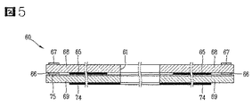
図5は図4のV−V線断面図であり、図6は図4のVI−VI線断面図である。 5 is a cross-sectional view taken along line VV in FIG. 4, and FIG. 6 is a cross-sectional view taken along line VI-VI in FIG.
図5及び図6に示すように、タッチシート60は、タッチスクリーンパターン部63及びタッチボタンパターン部65が形成された透光性絶縁層68、69を含む。透光性絶縁層68、69は、ポリエチレンフィルムで形成することができ、複数枚が積層された形態に形成することができる。
As shown in FIGS. 5 and 6, the
図5に示すように、タッチシート60の第2領域50は、内面にタッチボタンパターン部65が形成された第1透光性絶縁層68と、全面に導電膜74が形成されて第1透光性絶縁層68の下部に位置する第2透光性絶縁層69とからなる。第1透光性絶縁層68と第2透光性絶縁層69とは、接着剤層75により接着されている。第2透光性絶縁層69に形成された導電膜74は、内部の部品による電場の影響を遮断する役割を果たす。
As shown in FIG. 5, the
タッチボタンパターン部65は、内部の照明ユニット53の光が透過できるように、透光性又は半透光性材質で形成される。タッチスクリーンパターン部63及びタッチボタンパターン部65は、ITOをスパッタリングすることで形成することが好ましい。
The touch
第1透光性絶縁層68の縁部には、タッチスクリーンパターン部63のデータライン66をシールドする導電性シールドライン67が形成される。ここで、シールドライン67は、第1領域40に延びて形成されており、第1領域40に延びて形成されたタッチスクリーンパターン部63のデータライン66をシールドすることができる(図4及び図5参照)。
A
図4に示すように、シールドライン67は、タッチスクリーンパターン部63が形成された第1領域40と、タッチボタンパターン部65が形成された第2領域50とを区画する。タッチスクリーンパターン部63のデータライン66又はシールドライン67は、タッチスクリーンパターン部63及びタッチボタンパターン部65とは異なり、銅箔又は導電性メタルをプリントして形成することにより、製造コストを低減することができる。
As shown in FIG. 4, the
さらに、タッチシート60がタッチスクリーンパターン部63とタッチボタンパターン部65の両方を含むことにより、次のような利点がある。すなわち、タッチスクリーンパターンのみ形成されているタッチシートにプッシュボタンなどの手段を配置するために貫通孔を形成した場合にタッチスクリーンパターンがグリッド(図4参照)又はマトリクス状になっていることから発生する問題、例えばタッチスクリーンパターンへのタッチの感知が難しく、歪んだ信号を補正して正しい信号を抽出するためのさらなる複雑な技術的考慮を要するという問題を、最小限に抑えることができる。
Furthermore, since the
図5に示すように、シールドライン67は、タッチスクリーンパターン部63のデータライン66が配置された第1透光性絶縁層68の反対面に位置することにより、シールドライン67が占める面積を減少させると共にシールド効果を高める。
As shown in FIG. 5, the
シールドライン67は、照明ユニット53のグラウンドと電気的に短絡させることにより、タッチを精密に感知するタッチスクリーンパターン部63が照明ユニット53に影響されて誤動作することを防止することが好ましい。
It is preferable that the
図6に示すように、タッチスクリーンパターン部63は、横パターン部72と縦パターン部73の組み合わせからなり、横パターン部72が形成された透光性絶縁層68、縦パターン部73が形成された透光性絶縁層69、及び導電膜74が形成された透光性絶縁層71を含む。従って、ウィンドウ13の第1領域40へのタッチは横パターン部72及び縦パターン部73の静電容量などの変化により感知され、該当する横パターン部72と縦パターン部73の位置の組み合わせに応じてタッチされた位置に対応する入力動作が行われる。
As shown in FIG. 6, the touch
横パターン部72と縦パターン部73とは位置交換が可能である。また、横パターン部72及び縦パターン部73は、タッチボタンパターン部65と同様に、ITOをスパッタリングすることで形成できる。
The position of the
以上の図面を参照して、本発明を次のように理解することもできる。 The present invention can be understood as follows with reference to the above drawings.
タッチ感知シートは、異なる形態のタッチ入力が行われるように第1領域40及び第2領域50に分けられる平面を有する一体型シート60と、第1領域40に第1パターンで形成されるタッチ感知素子からなるタッチセンサアレイ63と、第2領域50に第2パターンで形成されるタッチ感知素子からなる複数のタッチ活性領域65とを含む。
The touch sensing sheet includes an
この場合、前記タッチ感知素子は、静電容量、抵抗、持続時間、及び圧力の少なくとも1つの変化を感知するように構成される。前記タッチ感知シートは、タッチセンサアレイ63を電気的に接続し、タッチセンサアレイ63及びタッチ活性領域65が一体型シート60の一端部でフレキシブルプリント基板70に接続されるように一体型シート60の縁部に沿って形成されるデータライン66、67をさらに含む。第2領域50には、タッチ活性領域65に隣接して配置されるプッシュボタンを設置できるように、少なくとも1つの開口61、62が形成される。一体型シート60は、タッチセンサアレイ63及びタッチ活性領域65に積層される複数の透光性絶縁層68、69、71を含む。一体型シート60は、透光性絶縁層68、69、71の最下部に配置され、一体型シート60の下に配置される電気部品からの電磁気的な干渉を最小限に抑える伝導層74をさらに含む。透光性絶縁層68、69、71は接着手段75、76により互いに貼り付けられる。このようなタッチ感知シートは携帯端末機に装着されるように形成される。
In this case, the touch sensing element is configured to sense at least one change in capacitance, resistance, duration, and pressure. The touch sensing sheet electrically connects the
また、以上の図面を参照して、本発明を次のように理解することもできる。 Further, the present invention can be understood as follows with reference to the above drawings.
すなわち、本発明は、ユーザの入力及び情報の出力のための平面を有するタッチ感知スクリーンと、前記タッチ感知スクリーンの平面の縁部でない部分に設置される少なくとも1つのメカニカルキーとを含み、前記タッチ感知スクリーンは、タッチセンサの第1パターンを有する第1領域と、タッチセンサの第2パターンを有する第2領域とを含むユーザインタフェースであるとも説明できる。この場合、前記タッチ感知スクリーンは、前記タッチセンサの第1パターンを形成するために前記第1領域に形成されるタッチマトリクスと、前記タッチセンサの第2パターンを形成するために前記メカニカルキーの周辺に形成される複数のタッチ活性領域とを含む。前記タッチマトリクス及びタッチ活性領域は、静電容量、抵抗、持続時間、及び圧力の少なくとも1つの変化を感知する。 That is, the present invention includes a touch-sensitive screen having a plane for user input and information output, and at least one mechanical key installed on a non-edge portion of the plane of the touch-sensitive screen. The sensing screen can also be described as a user interface including a first area having a first pattern of touch sensors and a second area having a second pattern of touch sensors. In this case, the touch sensing screen includes a touch matrix formed in the first region to form the first pattern of the touch sensor, and a periphery of the mechanical key to form the second pattern of the touch sensor. A plurality of touch active regions formed on the substrate. The touch matrix and the touch active area sense at least one change in capacitance, resistance, duration, and pressure.
図7は本発明の一実施形態による携帯端末機を示すブロック図である。 FIG. 7 is a block diagram illustrating a portable terminal according to an embodiment of the present invention.
図7に示すように、本発明の一実施形態による携帯端末機は、無線通信モジュール81、操作部15、23、26、51、60、画像入力部16、25、音響入力部24、ディスプレイモジュール41、音響出力部14、外部インタフェース27、放送受信モジュール86、メモリ84、感知部85、電源供給部87、制御部80などを含む。
As shown in FIG. 7, the mobile terminal according to the embodiment of the present invention includes a
操作部15、23、26、51、60は、図1〜図4に示すように構成され、ユーザが携帯端末機の動作を制御するために入力する入力データを制御部80に提供する。
The
制御部80は携帯端末機の全般的な動作を制御する。例えば、音声通話、データ通信、テレビ電話などに関連する制御及び処理を行う。また、制御部80は、通常の機能制御の他に、タッチシート60からタッチ信号を受信してその入力信号に基づく制御命令を実行する。
The
無線通信モジュール81は、アンテナ(符号なし)を介してネットワーク(例えば、移動通信基地局)と無線信号を送受信する。例えば、制御部80の制御下で音声データ、テキストデータ、画像データ、及び制御データの送受信を担当し、このために、送信する信号を変調して送信する送信部83と、受信した信号を復調する受信部82とを含む。
The
画像入力部16、25は、ユーザなどに対する静止画像又は動画像の撮影のためのカメラモジュール(又は、他のタイプの画像キャプチャモジュール)などの形態で実現できる。画像入力部16、25が使用されるモード、すなわち撮影モードやテレビ電話モードの場合、ディスプレイモジュール41は、制御部80の制御により、画像入力部16、25の各種機能を制御するための標識を表示する。
The
画像入力部16、25は、イメージセンサにより得られる静止画像や動画像などの画像フレームを処理する。画像入力部16、25で処理された画像フレームは、ディスプレイモジュール41に表示可能な画像データに変換され、ディスプレイモジュール41に出力される。また、画像入力部16、25で処理された画像フレームは、制御部80の制御下で、メモリ160に保存されるか、又は無線通信モジュール81により外部に伝送される。
The
音響入力部24は、通話モード、録音モード、又は音声認識モードなどで、マイクに入力された外部の音響信号を電気的な音声データに処理する。そして、処理された音声データは、通話モードの場合、無線通信モジュール81により移動通信基地局に送信可能な形態に変換され、無線通信モジュール81に出力される。録音モードの場合、処理された音声データはメモリ84に保存されるように出力される。
The
音響入力部24は、外部の音響信号が入力される過程で発生するノイズを除去するための様々なノイズ除去アルゴリズムを実現できる。
The
ディスプレイモジュール41は、携帯端末機で処理される情報を表示出力する。例えば、携帯端末機が通話モードの場合、制御部80の制御により、通話に関するUI(User Interface)又はGUI(Graphic User Interface)を表示出力する。また、携帯端末機がテレビ電話モード又は撮影モードの場合、制御部80の制御により、撮影された画像、又はUI、GUIを表示出力する。
The display module 41 displays and outputs information processed by the mobile terminal. For example, when the mobile terminal is in a call mode, the
ディスプレイモジュール41により出力される内容は、タッチシート60のタッチスクリーンパターン部63により入力可能な項目又はリストでもよい。
The content output by the display module 41 may be an item or list that can be input by the touch
音響出力部14は、呼受信モード、通話モード、録音モード、音声認識モード、又は放送受信モードなどで、制御部80の制御により、無線通信モジュール81から受信するか、又はメモリ84に保存されたオーディオデータを変換して外部に出力する。また、音響出力部14は、携帯端末機で実行される機能に関連する音響信号(例えば、呼信号受信音、メッセージ受信音など)を出力する。このような音響出力部14は、スピーカ、レシーバ、ブザーなどを含む。
The
外部インタフェース27は、携帯端末機に接続される全ての外部機器とのインタフェースの役割を果たす。例えば、有無線ヘッドセット、外部充電器、有無線データポート、カードソケット(例えば、メモリカード、SIMカード、UIMカード)などを含む。このような外部インタフェース27は、外部機器からデータを受信するか、供給された電源を携帯端末機内部の各構成要素に伝送するか、又は携帯端末機内部のデータを外部機器に送信する。
The
メモリ84は、制御部80の処理及び制御のためのプログラムを保存することもでき、入出力されるデータ(例えば、電話帳、メッセージ、静止画像、動画像など)の一時保存のための機能を実行することもできる。このようなメモリ84は、公知のハードディスク、カードタイプのメモリ(例えば、SDやXDメモリなど)、フラッシュメモリ、RAM、ROMなどを含む。
The
感知部85は、携帯端末機の開閉状態、携帯端末機の位置、ユーザの接触の有無などの携帯端末機の現在の状態を感知し、携帯端末機の動作を制御するための感知信号を発生する。例えば、携帯端末機がスライドタイプの場合、携帯端末機の開閉状態を感知してその感知結果を制御部80に出力することにより、携帯端末機の動作を制御させる。また、電源供給部87から電源が供給されたか否か、外部インタフェース27に外部機器が結合されたか否かなどに関する感知機能を果たす。
The
放送受信モジュール86は、衛星を介して又は地上波などで送信された放送信号を受信し、音響出力部14、ディスプレイモジュール41に出力可能な放送データの形態に変換して制御部80に出力する。また、放送受信モジュール86は、放送に関する付加データ(例えば、EPG(Electronic Program Guide)、チャネルリストなど)を受信する。放送受信モジュール86で変換された放送データ及び付加データは、メモリ84に保存することもできる。
The
本発明による携帯端末機は、前述した実施形態の構成と方法の適用に限定されるのではなく、各実施形態の全部又は一部を選択して組み合わせることにより様々な変形が可能である。 The portable terminal according to the present invention is not limited to the application of the configuration and method of the above-described embodiments, and various modifications can be made by selecting and combining all or a part of the embodiments.
Claims (29)
前記第1領域及び第2領域へのタッチを感知できるように構成されるタッチシートとを含み、
前記タッチシートは、
前記第1領域へのタッチを感知できるように複数の導電性ラインを有するタッチスクリーンパターン部と、
前記第2領域上に所定の面積を有するように配置されるタッチボタンパターン部と
を含むことを特徴とする携帯端末機。 A terminal body having a first area and a second area;
A touch sheet configured to sense a touch on the first region and the second region;
The touch sheet is
A touch screen pattern unit having a plurality of conductive lines so as to sense a touch on the first region;
And a touch button pattern unit arranged to have a predetermined area on the second region.
前記ディスプレイモジュールが前記第1領域に配置され、前記回路基板が前記第2領域に配置されることを特徴とする請求項1に記載の携帯端末機。 Inside the touch sheet, a display module for outputting visual information and a circuit board are provided,
The mobile terminal according to claim 1, wherein the display module is disposed in the first region, and the circuit board is disposed in the second region.
前記タッチスクリーンパターン部のデータラインが、前記透光性絶縁層の縁部に沿って配置され、前記タッチボタンパターン部のデータラインと集合してフレキシブルプリント基板に接続されることを特徴とする請求項5に記載の携帯端末機。 The touch screen pattern unit and the touch button pattern unit each include a data line for transmitting a signal,
The data line of the touch screen pattern part is disposed along an edge of the translucent insulating layer, and is combined with the data line of the touch button pattern part and connected to a flexible printed circuit board. Item 6. The mobile terminal according to Item 5.
前記シールドラインは、前記タッチスクリーンパターン部のデータラインが配置された前記透光性絶縁層の反対面に位置することを特徴とする請求項6に記載の携帯端末機。 The edge of the first region of the touch sheet further includes a conductive shield line that shields the data line of the touch screen pattern portion,
The mobile terminal according to claim 6, wherein the shield line is located on an opposite surface of the translucent insulating layer on which the data line of the touch screen pattern unit is disposed.
前記タッチスクリーンパターン部及びタッチボタンパターン部が、前記透光性絶縁層に透光性のITOをスパッタリングすることにより形成されることを特徴とする請求項5に記載の携帯端末機。 The translucent insulating layer is formed of a flexible resin material;
The mobile terminal according to claim 5, wherein the touch screen pattern part and the touch button pattern part are formed by sputtering light-transmitting ITO on the light-transmitting insulating layer.
前記第1本体には、前記第1領域、第2領域、及びタッチシートが形成されることを特徴とする請求項1に記載の携帯端末機。 The terminal body includes a first body and a second body slidably connected to the first body,
The mobile terminal of claim 1, wherein the first body includes the first area, the second area, and a touch sheet.
前記第1領域に第1パターンで形成されるタッチ感知素子からなるタッチセンサアレイと、
前記第2領域に第2パターンで形成されるタッチ感知素子からなる複数のタッチ活性領域と
を含むことを特徴とするタッチ感知シート。 An integrated sheet having a plane divided into a first area and a second area so that different types of touch input can be performed;
A touch sensor array comprising touch sensing elements formed in a first pattern in the first region;
A touch sensing sheet comprising: a plurality of touch active regions composed of touch sensing elements formed in a second pattern in the second region.
前記タッチ感知スクリーンの平面の縁部でない部分に設置される少なくとも1つのメカニカルキーとを含み、
前記タッチ感知スクリーンは、
タッチセンサの第1パターンを有する第1領域と、
タッチセンサの第2パターンを有する第2領域と
を含むことを特徴とするユーザインタフェース。 A touch-sensitive screen having a plane for user input and output of information;
At least one mechanical key installed on a non-edge portion of the plane of the touch-sensitive screen,
The touch-sensitive screen is
A first region having a first pattern of a touch sensor;
And a second area having a second pattern of the touch sensor.
前記タッチセンサの第1パターンを形成するために前記第1領域に形成されるタッチマトリクスと、
前記タッチセンサの第2パターンを形成するために前記メカニカルキーの周辺に形成される複数のタッチ活性領域と
を含むことを特徴とする請求項27に記載のユーザインタフェース。 The touch-sensitive screen is
A touch matrix formed in the first region to form a first pattern of the touch sensor;
28. The user interface according to claim 27, further comprising a plurality of touch active regions formed around the mechanical key to form a second pattern of the touch sensor.
Applications Claiming Priority (2)
| Application Number | Priority Date | Filing Date | Title |
|---|---|---|---|
| KR1020070114420A KR100904960B1 (en) | 2007-11-09 | 2007-11-09 | Portable terminal |
| KR10-2007-0114420 | 2007-11-09 |
Publications (2)
| Publication Number | Publication Date |
|---|---|
| JP2009123193A true JP2009123193A (en) | 2009-06-04 |
| JP5149103B2 JP5149103B2 (en) | 2013-02-20 |
Family
ID=40282349
Family Applications (1)
| Application Number | Title | Priority Date | Filing Date |
|---|---|---|---|
| JP2008215890A Active JP5149103B2 (en) | 2007-11-09 | 2008-08-25 | Portable terminal |
Country Status (12)
| Country | Link |
|---|---|
| US (3) | US9462097B2 (en) |
| EP (1) | EP2058729B1 (en) |
| JP (1) | JP5149103B2 (en) |
| KR (1) | KR100904960B1 (en) |
| CN (1) | CN101431563B (en) |
| AT (1) | ATE484788T1 (en) |
| BR (1) | BRPI0803740B1 (en) |
| DE (1) | DE602008002984D1 (en) |
| ES (1) | ES2354132T3 (en) |
| PT (1) | PT2058729E (en) |
| RU (1) | RU2399085C2 (en) |
| TW (1) | TWI387906B (en) |
Cited By (13)
| Publication number | Priority date | Publication date | Assignee | Title |
|---|---|---|---|---|
| KR20110080637A (en) * | 2010-01-06 | 2011-07-13 | 엘지전자 주식회사 | Mobile terminal |
| JP2011528828A (en) * | 2008-07-21 | 2011-11-24 | インファポイント システムズ リミテッド | Touch-type flat panel display |
| KR101129724B1 (en) * | 2010-04-26 | 2012-03-28 | 크루셜텍 (주) | Processing device for touch and pointing signal and electronic device having that |
| JP2012173855A (en) * | 2011-02-18 | 2012-09-10 | Nippon Seiki Co Ltd | Display device |
| KR101359737B1 (en) | 2011-12-23 | 2014-02-11 | 주식회사 엘지화학 | Touch panel and display apparatus comprising the same |
| JP5510451B2 (en) * | 2009-04-28 | 2014-06-04 | 日本電気株式会社 | Touch panel, touch panel manufacturing method, and electronic device |
| JP2014106960A (en) * | 2012-11-23 | 2014-06-09 | Elan Microelectronics Corp | Touch panel having virtual function button, method for manufacturing the same touch panel, and method for identifying touch competition on the same touch panel |
| WO2014174764A1 (en) * | 2013-04-24 | 2014-10-30 | パナソニックIpマネジメント株式会社 | Touch panel |
| JP2015503779A (en) * | 2011-12-25 | 2015-02-02 | 宸鴻科技(廈門)有限公司TPK Touch Solutions(Xiamen)Inc. | Touch panel and manufacturing method thereof |
| JP2015092352A (en) * | 2014-12-02 | 2015-05-14 | 京セラ株式会社 | Portable terminal and input control program |
| US9489091B2 (en) | 2013-05-16 | 2016-11-08 | Samsung Display Co., Ltd. | Organic light-emitting display panel |
| WO2017154617A1 (en) * | 2016-03-11 | 2017-09-14 | アルプス電気株式会社 | Electrostatic capacity sensor |
| JP2017530458A (en) * | 2014-09-03 | 2017-10-12 | 華為技術有限公司Huawei Technologies Co.,Ltd. | Terminal, touch control unit, touch screen, screen protector, operation detection apparatus and method |
Families Citing this family (45)
| Publication number | Priority date | Publication date | Assignee | Title |
|---|---|---|---|---|
| KR100904960B1 (en) | 2007-11-09 | 2009-06-26 | 엘지전자 주식회사 | Portable terminal |
| TWI460623B (en) * | 2009-07-14 | 2014-11-11 | Htc Corp | Touch-controlled electronic apparatus and related control method |
| CN201440650U (en) * | 2009-08-26 | 2010-04-21 | 珠海格力电器股份有限公司 | Touch control device |
| KR101649626B1 (en) | 2009-08-27 | 2016-08-19 | 엘지전자 주식회사 | Mobile terminal |
| FR2956514B1 (en) * | 2010-02-12 | 2012-09-21 | Sagem Wireless | PORTABLE TELEPHONE HAVING A MARKING |
| KR101104931B1 (en) | 2010-02-24 | 2012-01-12 | 주식회사 토비스 | Structure of touch panel using resistance film type and system comprising the touch panel and method for receiving touch input |
| KR101104930B1 (en) | 2010-02-24 | 2012-01-12 | 주식회사 토비스 | Structure of touch panel using resistance film type and system comprising the touch panel and method for receiving touch panel |
| KR101109313B1 (en) * | 2010-04-14 | 2012-01-31 | 삼성전기주식회사 | Display apparatus having touch screen panel |
| KR101148685B1 (en) * | 2010-07-14 | 2012-05-23 | 삼성전기주식회사 | Touch Screen |
| KR101164095B1 (en) | 2010-12-20 | 2012-07-12 | 엘지이노텍 주식회사 | Touch window and portable terminal therewith |
| DE102012005097A1 (en) * | 2011-03-30 | 2012-10-04 | Giesecke & Devrient Gmbh | Method for interacting a data carrier with a terminal |
| KR101303633B1 (en) * | 2011-06-13 | 2013-09-11 | 엘지이노텍 주식회사 | Self-Capacitance Touch window |
| WO2011137861A2 (en) * | 2011-07-01 | 2011-11-10 | 华为终端有限公司 | Terminal and method of manufacturing touch screen of terminal |
| ES2717267T3 (en) * | 2011-10-20 | 2019-06-20 | Huawei Tech Co Ltd | Mobile terminal comprising a cover unit with a key mechanism |
| KR101265650B1 (en) * | 2011-12-01 | 2013-05-22 | 엘지전자 주식회사 | Lighting apparatus and method of controlling the lighting apparatus using a remote controller |
| KR101916318B1 (en) * | 2012-04-26 | 2018-11-09 | 엘지이노텍 주식회사 | Touch panel and manufacturing method thereof |
| CN102830844A (en) * | 2012-08-17 | 2012-12-19 | 北京小米科技有限责任公司 | Touch screen misoperation prevention method, touch screen and mobile terminal |
| US9058941B2 (en) * | 2012-08-20 | 2015-06-16 | Apple Inc. | Floating switch assemblies and methods for making the same |
| US9030839B2 (en) * | 2012-10-18 | 2015-05-12 | Apple Inc. | Track pad acoustic features related to a portable computer |
| USD732040S1 (en) | 2013-01-29 | 2015-06-16 | Htc Corporation | Touch module for an electronic device |
| US9354738B2 (en) | 2013-02-07 | 2016-05-31 | Htc Corporation | Touch panel assembly and electronic apparatus |
| JP6119518B2 (en) | 2013-02-12 | 2017-04-26 | ソニー株式会社 | Sensor device, input device and electronic apparatus |
| TWI492163B (en) * | 2013-02-20 | 2015-07-11 | Smartdisplayer Technology Co Ltd | Electronic card and its capacitive touch sensing method |
| WO2014147943A1 (en) | 2013-03-18 | 2014-09-25 | ソニー株式会社 | Sensor device, input device, and electronic device |
| JP6142745B2 (en) * | 2013-09-10 | 2017-06-07 | ソニー株式会社 | Sensor device, input device and electronic apparatus |
| CN103576987A (en) * | 2013-10-18 | 2014-02-12 | 小米科技有限责任公司 | ITO thin film and terminal equipment |
| KR102168132B1 (en) | 2013-12-31 | 2020-10-21 | 삼성디스플레이 주식회사 | Organic light emitting device |
| CN104331182B (en) * | 2014-03-06 | 2017-08-25 | 广州三星通信技术研究有限公司 | Portable terminal with auxiliary touch-screen |
| JP2015190859A (en) | 2014-03-28 | 2015-11-02 | ソニー株式会社 | Sensor device, input device, and electronic apparatus |
| US20150346863A1 (en) * | 2014-05-29 | 2015-12-03 | Kabushiki Kaisha Toshiba | Touch panel and electronic device with touch panel |
| US20190045620A1 (en) * | 2014-07-09 | 2019-02-07 | Schreiner Group Gmbh & Co. Kg | Sensor device with a flexible electrical conductor structure |
| KR101847075B1 (en) * | 2014-12-18 | 2018-04-09 | 삼성전자주식회사 | Electronic device |
| USD819742S1 (en) * | 2015-03-04 | 2018-06-05 | Americhip, Inc | Vertical digital video blade |
| USD819741S1 (en) * | 2015-03-04 | 2018-06-05 | Americhip, Inc. | Horizontal digital video blade |
| USD791236S1 (en) * | 2015-03-04 | 2017-07-04 | Americhip, Inc. | Digital video blade |
| USD819743S1 (en) * | 2015-03-04 | 2018-06-05 | Americhip, Inc. | Vertical digital video blade |
| JP6626130B2 (en) | 2015-06-04 | 2019-12-25 | 華為技術有限公司Huawei Technologies Co.,Ltd. | Mobile terminal and heat dissipation and shield structure |
| KR101841583B1 (en) | 2016-12-05 | 2018-03-26 | 삼성전자주식회사 | Mounting structure for a module in an electronic device |
| CN107065265A (en) * | 2017-05-05 | 2017-08-18 | 广东欧珀移动通信有限公司 | Display device and mobile electronic terminal |
| CN110770686B (en) * | 2017-08-01 | 2023-09-01 | 株式会社和冠 | Sensor for detecting pen signal sent by pen |
| US10691176B2 (en) * | 2018-07-12 | 2020-06-23 | Google Llc | Textured pattern surface for a computing device |
| CN109817089A (en) * | 2019-01-29 | 2019-05-28 | 信利光电股份有限公司 | A kind of manufacturing method of display device, electronic device and display device |
| CN110830639B (en) * | 2019-10-28 | 2021-10-01 | 维沃移动通信有限公司 | Electronic equipment |
| CN113540788B (en) | 2020-04-17 | 2022-09-27 | 荣耀终端有限公司 | Electronic device |
| US11966544B2 (en) | 2022-07-29 | 2024-04-23 | Apple Inc. | Data line shielding for electronic device displays with touch sensors |
Citations (2)
| Publication number | Priority date | Publication date | Assignee | Title |
|---|---|---|---|---|
| JPH1039993A (en) * | 1996-07-26 | 1998-02-13 | Fujitsu Kiden Ltd | Transparent touch panel and input device utilizing the same |
| JP2004038927A (en) * | 2002-03-16 | 2004-02-05 | Hewlett Packard Co <Hp> | Display and touch screen |
Family Cites Families (25)
| Publication number | Priority date | Publication date | Assignee | Title |
|---|---|---|---|---|
| US4690680A (en) * | 1986-06-27 | 1987-09-01 | The Procter & Gamble Company | Adhesive attachment means for absorbent articles |
| US7911456B2 (en) * | 1992-06-08 | 2011-03-22 | Synaptics Incorporated | Object position detector with edge motion feature and gesture recognition |
| US7151528B2 (en) * | 1999-06-22 | 2006-12-19 | Cirque Corporation | System for disposing a proximity sensitive touchpad behind a mobile phone keypad |
| US6462941B1 (en) * | 2000-06-30 | 2002-10-08 | Palm, Inc. | Method and apparatus for backlighting a handwriting input area for a portable computing device |
| US6704004B1 (en) * | 2000-08-17 | 2004-03-09 | Nokia Mobile Phones Ltd. | Arrangement for integration of key illumination into keymat of portable electronic devices |
| JP2002215330A (en) | 2001-01-16 | 2002-08-02 | Digital Electronics Corp | User interface device, touch panel, membrane switch, and method of manufacturing the user interface device |
| EP1405298A4 (en) * | 2001-06-06 | 2009-04-29 | Cirque Corp | System for disposing a proximity sensitive touchpad behind a mobile phone keymat |
| USD467235S1 (en) * | 2001-06-11 | 2002-12-17 | Handspring, Inc. | Hand-held device with handwriting area |
| US6975304B1 (en) | 2001-06-11 | 2005-12-13 | Handspring, Inc. | Interface for processing of an alternate symbol in a computer device |
| JP3926590B2 (en) | 2001-07-24 | 2007-06-06 | アルプス電気株式会社 | Coordinate input device and electronic device |
| JP3937982B2 (en) | 2002-08-29 | 2007-06-27 | ソニー株式会社 | INPUT / OUTPUT DEVICE AND ELECTRONIC DEVICE HAVING INPUT / OUTPUT DEVICE |
| EP1589407B1 (en) | 2004-04-22 | 2007-10-10 | Sony Ericsson Mobile Communications AB | Control interface for electronic device |
| RU44399U1 (en) | 2004-08-23 | 2005-03-10 | Общество с ограниченной ответственностью "Инновационная производственная компания Волгарь" | COMPACT AUTONOMOUS DEVICE FOR RECEIPT, STORAGE, PROCESSING AND DISPLAY OF INFORMATION (OPTIONS) |
| KR101374546B1 (en) * | 2005-07-25 | 2014-03-17 | 플라스틱 로직 리미티드 | Flexible touch screen display |
| US7603143B2 (en) * | 2005-08-26 | 2009-10-13 | Lg Electronics Inc. | Mobile telecommunication handset having touch pad |
| US7825907B2 (en) * | 2005-08-30 | 2010-11-02 | Lg Electronics Inc. | Touch key assembly for a mobile terminal |
| CN100511535C (en) | 2005-10-12 | 2009-07-08 | 中兴通讯股份有限公司 | Touch keyboard and mobile terminal with same |
| KR100751943B1 (en) * | 2006-03-28 | 2007-08-24 | 엘지전자 주식회사 | Facing case and mobile terminal having the same |
| US7556204B2 (en) * | 2006-04-19 | 2009-07-07 | Nokia Corproation | Electronic apparatus and method for symbol input |
| US7600880B2 (en) * | 2006-06-12 | 2009-10-13 | Motorola, Inc. | Device with modal lighting control and method thereof |
| US7492602B2 (en) * | 2006-07-14 | 2009-02-17 | Lg Electronics Inc. | Mobile terminal |
| US8226474B2 (en) * | 2006-09-08 | 2012-07-24 | Igt | Mobile gaming devices for use in a gaming network having gaming and non-gaming zones |
| KR20080005070U (en) * | 2007-04-27 | 2008-10-30 | (주)멜파스 | Portable touch-type keyboard |
| US7876274B2 (en) * | 2007-06-21 | 2011-01-25 | Apple Inc. | Wireless handheld electronic device |
| KR100904960B1 (en) | 2007-11-09 | 2009-06-26 | 엘지전자 주식회사 | Portable terminal |
-
2007
- 2007-11-09 KR KR1020070114420A patent/KR100904960B1/en active IP Right Grant
-
2008
- 2008-02-18 PT PT08101720T patent/PT2058729E/en unknown
- 2008-02-18 ES ES08101720T patent/ES2354132T3/en active Active
- 2008-02-18 AT AT08101720T patent/ATE484788T1/en not_active IP Right Cessation
- 2008-02-18 EP EP08101720A patent/EP2058729B1/en active Active
- 2008-02-18 DE DE602008002984T patent/DE602008002984D1/en active Active
- 2008-06-23 TW TW097123355A patent/TWI387906B/en active
- 2008-06-27 US US12/163,992 patent/US9462097B2/en active Active
- 2008-07-09 RU RU2008128215/09A patent/RU2399085C2/en active
- 2008-07-15 BR BRPI0803740-0A patent/BRPI0803740B1/en not_active IP Right Cessation
- 2008-07-16 CN CN2008101339794A patent/CN101431563B/en active Active
- 2008-08-25 JP JP2008215890A patent/JP5149103B2/en active Active
-
2016
- 2016-03-30 US US15/085,136 patent/US9456062B2/en active Active
- 2016-09-09 US US15/261,510 patent/US9880690B2/en active Active
Patent Citations (2)
| Publication number | Priority date | Publication date | Assignee | Title |
|---|---|---|---|---|
| JPH1039993A (en) * | 1996-07-26 | 1998-02-13 | Fujitsu Kiden Ltd | Transparent touch panel and input device utilizing the same |
| JP2004038927A (en) * | 2002-03-16 | 2004-02-05 | Hewlett Packard Co <Hp> | Display and touch screen |
Cited By (18)
| Publication number | Priority date | Publication date | Assignee | Title |
|---|---|---|---|---|
| JP2011528828A (en) * | 2008-07-21 | 2011-11-24 | インファポイント システムズ リミテッド | Touch-type flat panel display |
| JP5510451B2 (en) * | 2009-04-28 | 2014-06-04 | 日本電気株式会社 | Touch panel, touch panel manufacturing method, and electronic device |
| KR20110080637A (en) * | 2010-01-06 | 2011-07-13 | 엘지전자 주식회사 | Mobile terminal |
| KR101631952B1 (en) | 2010-01-06 | 2016-06-20 | 엘지전자 주식회사 | Mobile terminal |
| KR101129724B1 (en) * | 2010-04-26 | 2012-03-28 | 크루셜텍 (주) | Processing device for touch and pointing signal and electronic device having that |
| JP2012173855A (en) * | 2011-02-18 | 2012-09-10 | Nippon Seiki Co Ltd | Display device |
| KR101359737B1 (en) | 2011-12-23 | 2014-02-11 | 주식회사 엘지화학 | Touch panel and display apparatus comprising the same |
| JP2015503779A (en) * | 2011-12-25 | 2015-02-02 | 宸鴻科技(廈門)有限公司TPK Touch Solutions(Xiamen)Inc. | Touch panel and manufacturing method thereof |
| US9158400B2 (en) | 2012-11-23 | 2015-10-13 | Elan Microelectronics Corporation | Touch panel having virtual function button, method of manufacturing the same, and method of identifying touch conflict on the same |
| JP2014106960A (en) * | 2012-11-23 | 2014-06-09 | Elan Microelectronics Corp | Touch panel having virtual function button, method for manufacturing the same touch panel, and method for identifying touch competition on the same touch panel |
| WO2014174764A1 (en) * | 2013-04-24 | 2014-10-30 | パナソニックIpマネジメント株式会社 | Touch panel |
| JPWO2014174764A1 (en) * | 2013-04-24 | 2017-02-23 | パナソニックIpマネジメント株式会社 | Touch panel |
| US10126887B2 (en) | 2013-04-24 | 2018-11-13 | Panasonic Intellectual Property Management Co., Ltd. | Touch panel |
| US9489091B2 (en) | 2013-05-16 | 2016-11-08 | Samsung Display Co., Ltd. | Organic light-emitting display panel |
| JP2017530458A (en) * | 2014-09-03 | 2017-10-12 | 華為技術有限公司Huawei Technologies Co.,Ltd. | Terminal, touch control unit, touch screen, screen protector, operation detection apparatus and method |
| US10175840B2 (en) | 2014-09-03 | 2019-01-08 | Huawei Technologies Co., Ltd. | Terminal, touch control unit, touchscreen, screen protector, and operation detection apparatus and method |
| JP2015092352A (en) * | 2014-12-02 | 2015-05-14 | 京セラ株式会社 | Portable terminal and input control program |
| WO2017154617A1 (en) * | 2016-03-11 | 2017-09-14 | アルプス電気株式会社 | Electrostatic capacity sensor |
Also Published As
| Publication number | Publication date |
|---|---|
| EP2058729A1 (en) | 2009-05-13 |
| EP2058729B1 (en) | 2010-10-13 |
| CN101431563A (en) | 2009-05-13 |
| JP5149103B2 (en) | 2013-02-20 |
| KR100904960B1 (en) | 2009-06-26 |
| PT2058729E (en) | 2011-01-18 |
| US20160212251A1 (en) | 2016-07-21 |
| TW200921484A (en) | 2009-05-16 |
| TWI387906B (en) | 2013-03-01 |
| BRPI0803740A2 (en) | 2009-07-14 |
| CN101431563B (en) | 2013-04-24 |
| US20090122026A1 (en) | 2009-05-14 |
| US9462097B2 (en) | 2016-10-04 |
| ES2354132T3 (en) | 2011-03-10 |
| RU2008128215A (en) | 2010-01-20 |
| DE602008002984D1 (en) | 2010-11-25 |
| US20160378228A1 (en) | 2016-12-29 |
| US9456062B2 (en) | 2016-09-27 |
| BRPI0803740B1 (en) | 2020-02-18 |
| RU2399085C2 (en) | 2010-09-10 |
| US9880690B2 (en) | 2018-01-30 |
| ATE484788T1 (en) | 2010-10-15 |
Similar Documents
| Publication | Publication Date | Title |
|---|---|---|
| JP5149103B2 (en) | Portable terminal | |
| KR101301521B1 (en) | Portable terminal | |
| JP4849483B2 (en) | Mobile terminal | |
| US9489129B2 (en) | Mobile terminal setting first and second control commands to user divided first and second areas of a backside touch screen | |
| CN105320230B (en) | Hand-hold electronic equipments and for sense touch and power method | |
| US8280446B2 (en) | Mobile terminal having touch input device | |
| KR101485392B1 (en) | Portable terminal | |
| EP1887597B1 (en) | Mobile terminal | |
| KR101649626B1 (en) | Mobile terminal | |
| JP2014078874A (en) | Terminal device | |
| KR101772078B1 (en) | Mobile terminal | |
| KR20140001701A (en) | Mobile terminal | |
| KR101409872B1 (en) | Portable terminal | |
| KR101301522B1 (en) | Portable terminal | |
| KR101490167B1 (en) | Portable Terminal | |
| KR101504213B1 (en) | Switch assembley and portable terminal having the same | |
| KR101604716B1 (en) | Touch-sensitive input unit and portable terminal having the same | |
| KR20110058524A (en) | Portable terminal |
Legal Events
| Date | Code | Title | Description |
|---|---|---|---|
| A131 | Notification of reasons for refusal |
Free format text: JAPANESE INTERMEDIATE CODE: A131 Effective date: 20100901 |
|
| A521 | Request for written amendment filed |
Free format text: JAPANESE INTERMEDIATE CODE: A523 Effective date: 20101126 |
|
| A131 | Notification of reasons for refusal |
Free format text: JAPANESE INTERMEDIATE CODE: A131 Effective date: 20110209 |
|
| A521 | Request for written amendment filed |
Free format text: JAPANESE INTERMEDIATE CODE: A523 Effective date: 20110419 |
|
| A02 | Decision of refusal |
Free format text: JAPANESE INTERMEDIATE CODE: A02 Effective date: 20110902 |
|
| A521 | Request for written amendment filed |
Free format text: JAPANESE INTERMEDIATE CODE: A523 Effective date: 20111031 |
|
| A911 | Transfer to examiner for re-examination before appeal (zenchi) |
Free format text: JAPANESE INTERMEDIATE CODE: A911 Effective date: 20111202 |
|
| A912 | Re-examination (zenchi) completed and case transferred to appeal board |
Free format text: JAPANESE INTERMEDIATE CODE: A912 Effective date: 20120113 |
|
| A521 | Request for written amendment filed |
Free format text: JAPANESE INTERMEDIATE CODE: A523 Effective date: 20121025 |
|
| A61 | First payment of annual fees (during grant procedure) |
Free format text: JAPANESE INTERMEDIATE CODE: A61 Effective date: 20121129 |
|
| R150 | Certificate of patent or registration of utility model |
Ref document number: 5149103 Country of ref document: JP Free format text: JAPANESE INTERMEDIATE CODE: R150 Free format text: JAPANESE INTERMEDIATE CODE: R150 |
|
| FPAY | Renewal fee payment (event date is renewal date of database) |
Free format text: PAYMENT UNTIL: 20151207 Year of fee payment: 3 |
|
| R250 | Receipt of annual fees |
Free format text: JAPANESE INTERMEDIATE CODE: R250 |
|
| R250 | Receipt of annual fees |
Free format text: JAPANESE INTERMEDIATE CODE: R250 |
|
| R250 | Receipt of annual fees |
Free format text: JAPANESE INTERMEDIATE CODE: R250 |
|
| R250 | Receipt of annual fees |
Free format text: JAPANESE INTERMEDIATE CODE: R250 |
|
| R250 | Receipt of annual fees |
Free format text: JAPANESE INTERMEDIATE CODE: R250 |
|
| R250 | Receipt of annual fees |
Free format text: JAPANESE INTERMEDIATE CODE: R250 |
|
| R250 | Receipt of annual fees |
Free format text: JAPANESE INTERMEDIATE CODE: R250 |
|
| R250 | Receipt of annual fees |
Free format text: JAPANESE INTERMEDIATE CODE: R250 |
|
| R250 | Receipt of annual fees |
Free format text: JAPANESE INTERMEDIATE CODE: R250 |