JP2009111460A - Communication device - Google Patents
Communication device Download PDFInfo
- Publication number
- JP2009111460A JP2009111460A JP2007278673A JP2007278673A JP2009111460A JP 2009111460 A JP2009111460 A JP 2009111460A JP 2007278673 A JP2007278673 A JP 2007278673A JP 2007278673 A JP2007278673 A JP 2007278673A JP 2009111460 A JP2009111460 A JP 2009111460A
- Authority
- JP
- Japan
- Prior art keywords
- circuit unit
- transmission
- circuit
- data
- timer
- Prior art date
- Legal status (The legal status is an assumption and is not a legal conclusion. Google has not performed a legal analysis and makes no representation as to the accuracy of the status listed.)
- Pending
Links
Images

Classifications
-
- Y—GENERAL TAGGING OF NEW TECHNOLOGICAL DEVELOPMENTS; GENERAL TAGGING OF CROSS-SECTIONAL TECHNOLOGIES SPANNING OVER SEVERAL SECTIONS OF THE IPC; TECHNICAL SUBJECTS COVERED BY FORMER USPC CROSS-REFERENCE ART COLLECTIONS [XRACs] AND DIGESTS
- Y02—TECHNOLOGIES OR APPLICATIONS FOR MITIGATION OR ADAPTATION AGAINST CLIMATE CHANGE
- Y02D—CLIMATE CHANGE MITIGATION TECHNOLOGIES IN INFORMATION AND COMMUNICATION TECHNOLOGIES [ICT], I.E. INFORMATION AND COMMUNICATION TECHNOLOGIES AIMING AT THE REDUCTION OF THEIR OWN ENERGY USE
- Y02D30/00—Reducing energy consumption in communication networks
- Y02D30/70—Reducing energy consumption in communication networks in wireless communication networks
Landscapes
- Arrangements For Transmission Of Measured Signals (AREA)
- Mobile Radio Communication Systems (AREA)
Abstract
Description
本発明は、センサネットワークシステム等の通信装置に関し、特に低消費電力化を図る必要があるバッテリ駆動の無線通信装置に関する。 The present invention relates to a communication device such as a sensor network system, and more particularly to a battery-driven wireless communication device that needs to reduce power consumption.
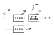
図2は、従来の通信装置の例を示した概略のブロック図である。
図2において、通信装置100は、センサ等のような所定の機能を有する素子、回路又は装置から得られたデータを無線送信するものであり、例えばセンサから得られたデータがデータ保持回路101に書き込まれ、データ保持回路101に書き込まれたデータは送信回路102によってアンテナ103から送信される。また、受信回路104は、アンテナ103を使用してデータの受信を行う。
FIG. 2 is a schematic block diagram showing an example of a conventional communication apparatus.
In FIG. 2, a
なお、本発明と異なるが、間欠受信待ち受け機器において、電文を送信したときにある時間まで待ち受け時間の周期を短くするように切り替えることで通信効率を向上させるようにしたもの(例えば、特許文献1参照。)や、電源が起動してからキャリアセンスするまでの時間を、周波数判定の基準を緩くすることによって短縮し、データ復調時には正確に復調できるように周波数判定の基準を厳しくして平均消費電流を削減するようにしたもの(例えば、特許文献2参照。)があった。また、複数のチャンネルを使用し、間欠動作を可能にしかつ間欠動作時に他のシステムが電波を使用中であっても自動的に空きチャンネルにより送信装置から同期信号を送信し、受信装置において同期信号を検出して間欠動作のタイミングを調整することができるものがあった(例えば、特許文献3参照。)。
しかし、図2のような構成では、データ保持回路101に書き込まれたデータをそのまま送信し続けるため、不要なデータをも送信されることから無駄な電力を消費していた。また、受信回路104は、常時、外部から送信されたあらゆるデータを受信することができるだけの充分な消費電流で作動しており、特に、通信装置がバッテリで駆動されている場合、該バッテリの消耗が早くなるという問題があった。
However, in the configuration as shown in FIG. 2, since the data written in the
本発明は、このような問題を解決するためになされたものであり、低消費電力化を図ることができる通信装置を得ることを目的とする。 The present invention has been made to solve such a problem, and an object of the present invention is to obtain a communication device capable of reducing power consumption.
この発明に係る通信装置は、入力された制御信号に応じて、外部の装置から送信された所定の起動信号のみを受信するために必要な最低限の消費電流で作動する低消費電流動作モードと、前記外部の装置から送信されたすべての信号を受信するために必要な消費電流で作動する通常動作モードのいずれかで作動する、前記外部の装置から送信された信号の受信を行う受信回路部と、
該受信回路部で受信した信号のデータを記憶する記憶回路部と、
該記憶回路部に記憶されたデータから、前記受信回路部の動作モードの切り換えを行う受信制御回路部と、
を備え、
前記受信制御回路部は、前記受信回路部に対して、前記起動信号が受信されるまでは前記低消費電流動作モードで作動させ、前記起動信号が受信されると前記通常動作モードで作動させるものである。
The communication device according to the present invention includes a low current consumption operation mode that operates with a minimum current consumption required to receive only a predetermined activation signal transmitted from an external device in accordance with an input control signal. A receiving circuit unit for receiving a signal transmitted from the external device, operating in one of the normal operation modes operating at a current consumption required to receive all signals transmitted from the external device When,
A storage circuit unit for storing data of signals received by the reception circuit unit;
From the data stored in the storage circuit unit, a reception control circuit unit for switching the operation mode of the reception circuit unit,
With
The reception control circuit unit operates the reception circuit unit in the low current consumption operation mode until the activation signal is received, and operates in the normal operation mode when the activation signal is received. It is.
また、所定の機能を有する素子、回路又は装置から得られたデータを保持するデータ保持回路部と、
入力された制御信号に応じて、該データ保持回路部に保持されたデータの送信を行う送信回路部と、
該送信回路部による送信動作が開始されてからの経過時間を計測するタイマ回路部と、
該タイマ回路部の計測時間が所定値以下であるか否かの判定を行うタイマ判定回路部と、
該タイマ判定回路部の判定結果に応じて前記送信回路部の送信動作制御を行う送信制御回路部と、
を備え、
前記データ保持回路部は、前記タイマ判定回路部の判定結果から、前記送信回路部による送信動作が開始されてから所定時間を経過したことを検出すると、前記得られたデータを保持する動作を開始するようにした。
In addition, a data holding circuit unit that holds data obtained from an element, circuit, or device having a predetermined function;
A transmission circuit unit for transmitting data held in the data holding circuit unit according to the input control signal;
A timer circuit unit for measuring an elapsed time after the transmission operation by the transmission circuit unit is started; and
A timer determination circuit unit for determining whether or not the measurement time of the timer circuit unit is a predetermined value or less;
A transmission control circuit unit that performs transmission operation control of the transmission circuit unit according to a determination result of the timer determination circuit unit;
With
The data holding circuit unit starts the operation of holding the obtained data when it detects from the determination result of the timer determination circuit unit that a predetermined time has passed since the transmission operation by the transmission circuit unit was started. I tried to do it.
また、この発明に係る通信装置は、センサ等のような所定の機能を有する素子、回路又は装置から得られたデータを送信する通信装置において、
前記データを保持するデータ保持回路部と、
入力された制御信号に応じて、該データ保持回路部に保持されたデータの送信を行う送信回路部と、
該送信回路部による送信動作が開始されてからの経過時間を計測するタイマ回路部と、
該タイマ回路部の計測時間が所定値以下であるか否かの判定を行うタイマ判定回路部と、
該タイマ判定回路部の判定結果に応じて前記送信回路部の送信動作制御を行う送信制御回路部と、
を備え、
前記データ保持回路部は、前記タイマ判定回路部の判定結果から、前記送信回路部による送信動作が開始されてから所定時間を経過したことを検出すると、前記データを保持する動作を開始するものである。
Further, the communication device according to the present invention is a communication device for transmitting data obtained from an element, circuit or device having a predetermined function such as a sensor.
A data holding circuit unit for holding the data;
A transmission circuit unit for transmitting data held in the data holding circuit unit according to the input control signal;
A timer circuit unit for measuring an elapsed time after the transmission operation by the transmission circuit unit is started; and
A timer determination circuit unit for determining whether or not the measurement time of the timer circuit unit is a predetermined value or less;
A transmission control circuit unit that performs transmission operation control of the transmission circuit unit according to a determination result of the timer determination circuit unit;
With
The data holding circuit unit starts the operation of holding the data when it detects from the determination result of the timer determination circuit unit that a predetermined time has elapsed since the transmission operation by the transmission circuit unit was started. is there.
また、前記所定の機能を有する素子、回路又は装置の動作制御を行う制御回路部を備え、該制御回路部は、前記タイマ判定回路部の判定結果から、前記送信回路部による送信動作が開始されてから所定時間を経過したことを検出すると、前記所定の機能を有する素子、回路又は装置の動作を開始させるようにした。 In addition, a control circuit unit that performs operation control of the element, circuit, or device having the predetermined function is provided, and the control circuit unit starts transmission operation by the transmission circuit unit from the determination result of the timer determination circuit unit. When it is detected that a predetermined time has elapsed since then, the operation of the element, circuit or device having the predetermined function is started.
本発明の通信装置によれば、受信動作が稀にしか起こらない待ち受け時は、容易に受信可能な信号のみを受信できるだけの動作を行うのに必要な最低限の電流値まで消費電流を低減させるようにしたことから、低消費電力化を図ることができる。 According to the communication device of the present invention, when the reception operation rarely occurs, the current consumption is reduced to the minimum current value necessary for performing an operation capable of receiving only a signal that can be easily received. As a result, low power consumption can be achieved.
また、前記データ保持回路部は、前記タイマ判定回路部の判定結果から、前記送信回路部による送信動作が開始されてから所定時間を経過したことを検出すると、前記データを保持する動作を開始するようにしたことから、取り込んだデータをまとめて送信することが可能となり、送信の効率化を図ることができるため、消費電力の低減を図ることができる。 In addition, the data holding circuit unit starts the operation of holding the data when detecting from the determination result of the timer determination circuit unit that a predetermined time has elapsed since the transmission operation by the transmission circuit unit was started. As a result, it is possible to collectively transmit the captured data, and to improve the efficiency of transmission, so that power consumption can be reduced.
また、前記送信回路部による送信動作が開始されてから所定時間を経過したことを検出すると、前記所定の機能を有する素子、回路又は装置の動作を開始させるようにしたことから、前記所定の機能を有する素子、回路又は装置の消費電力をも低減させることができる。 In addition, since the operation of the element, circuit, or device having the predetermined function is started when it is detected that a predetermined time has elapsed since the transmission operation by the transmission circuit unit is started, the predetermined function The power consumption of an element, circuit, or device having the above can also be reduced.
次に、図面に示す実施の形態に基づいて、本発明を詳細に説明する。
第1の実施の形態.
図1は、本発明の第1の実施の形態における通信装置の構成例を示したブロック図である。
図1において、通信装置1は、センサ等のような所定の機能を有する素子、回路又は装置から得られたデータを無線送信するものであり、以下、所定の機能を有するセンサ20から得られたデータを無線送信する場合を例にして説明する。
Next, the present invention will be described in detail based on the embodiments shown in the drawings.
First embodiment.
FIG. 1 is a block diagram showing a configuration example of a communication apparatus according to the first embodiment of the present invention.
In FIG. 1, a communication device 1 wirelessly transmits data obtained from an element, circuit, or device having a predetermined function such as a sensor. Hereinafter, the communication device 1 is obtained from a
通信装置1は、アンテナ2と、該アンテナ2を使用してデータ信号の送信を行う送信回路3と、該送信回路3の送信動作の制御を行う送信制御回路4と、センサ20からデータを取り込んで保持するデータ保持回路5と、センサ20の動作制御を行うセンサ制御回路6と、前回の送信からの経過時間を計測するタイマ回路7と、該タイマ回路7によって計測された時間が所定値以下であるか否かの判定を行うタイマ判定回路8とを備えている。更に、通信装置1は、アンテナ2を使用してデータの受信を行う受信回路11と、該受信回路11の受信動作の制御を行う受信制御回路12と、受信回路11で受信された設定データが書き込まれるレジスタ13とを備えている。
The communication device 1 captures data from an antenna 2, a transmission circuit 3 that transmits a data signal using the antenna 2, a transmission control circuit 4 that controls transmission operation of the transmission circuit 3, and a
なお、送信回路3は送信回路部を、送信制御回路4は送信制御回路部を、データ保持回路5はデータ保持回路部を、センサ制御回路6は制御回路部を、タイマ回路7はタイマ回路部を、タイマ判定回路8はタイマ判定回路部をそれぞれなす。また、受信回路11は受信回路部を、受信制御回路12は受信制御回路部を、レジスタ13は記憶回路部を、センサ20は所定の機能を有する素子、回路又は装置をそれぞれなす。
The transmission circuit 3 is a transmission circuit unit, the transmission control circuit 4 is a transmission control circuit unit, the
送信回路3は、送信制御回路4からの制御信号に応じてアンテナ2を介した信号送信を行い、データ保持回路5に保持されたデータは、送信回路3に出力される。また、タイマ回路7は、送信制御回路4から送信回路3に出力された制御信号が入力されており、該制御信号を使用して前回の送信からの経過時間を計測し、タイマ判定回路8は、タイマ回路7の計測時間が所定値以下であるか否かの判定結果を送信制御回路4に出力する。送信制御回路4は、タイマ判定回路8からの判定結果に応じて送信回路3の動作制御を行う。送信制御回路4は、タイマ判定回路8によってタイマ回路7の計測時間が所定値以下であると判定された場合は、送信回路3に対して送信動作を禁止し、タイマ判定回路8によってタイマ回路7の計測時間が所定値を超えていると判定された場合は、送信回路3に対して送信動作を行わせる。
The transmission circuit 3 performs signal transmission via the antenna 2 according to the control signal from the transmission control circuit 4, and the data held in the
また、データ保持回路5は、タイマ判定回路8の判定結果に応じてセンサ20からのデータを保持する動作を行い、センサ制御回路6は、タイマ判定回路8の判定結果に応じてセンサ20の動作制御を行う。
受信回路11は、受信制御回路12からの制御信号に応じて、所定の信号、例えば起動信号wakeupのみを受信できる最低限の消費電流で作動する待ち受け動作モードと、一連のデータをある程度の信頼性を保って受信できる消費電流で作動する通常動作モードのいずれかで作動する。受信回路11の動作モードの切り換えは外部の装置から送信された設定(又は指令)に基づいて行われ、受信回路11で受信した該設定はレジスタ13に格納される。受信制御回路12は、レジスタ13に格納された設定に基づいて、受信回路11の動作モードの切り換えを行う。
The
In response to a control signal from the
このような構成において、まず始めに、受信回路11が待ち受け動作モードになっているとする。すなわち、受信回路11のバイアス状態は極力低消費電力になるようになっており、起動信号wakeupのみを受信することができる。ここで、起動信号wakeupは、外部の装置、例えば親機から発信されるものであり、通常の送信信号よりもパワーを大きくする等して受信しやすい信号になっている。このようにすることにより、受信回路11は、構成する回路、例えばローノイズアンプ(以下、LNAと呼ぶ)のバイアス電流を低減させてゲインを小さくする等して消費電流を小さくしても起動信号wakeupを受信することができる。 In such a configuration, first, it is assumed that the receiving circuit 11 is in a standby operation mode. That is, the bias state of the receiving circuit 11 is as low power consumption as possible, and only the activation signal wakeup can be received. Here, the activation signal wakeup is transmitted from an external device, for example, a parent device, and is a signal that is easy to receive by increasing the power compared to a normal transmission signal. In this way, the reception circuit 11 can start the signal Wakeup even if the current consumption is reduced by reducing the bias current of a constituent circuit, for example, a low noise amplifier (hereinafter referred to as LNA) to reduce the gain. Can be received.
受信回路11は、起動信号wakeupを受信すると、該受信した起動信号wakeupのデータをレジスタ13に格納し、受信制御回路12は、レジスタ13に格納された該データに基づいて、受信回路11を通常動作モードで作動させる。受信回路11が通常動作モードで作動すると、受信回路11の消費電流が増加するが、その分、LNAのバイアス電流を増やしてゲインを高めたり、NFを低くして感度を高める等のようなことを行うことができ、データ取り込み品質を向上させることができる。一連のデータ受信が終了すると、データ受信が終了したことを示す受信信号のデータがレジスタ13に格納され、受信制御回路12は、受信回路11に対して待ち受け動作モードに移行させる。
When receiving the activation signal wakeup, the reception circuit 11 stores the data of the received activation signal wakeup in the
また、センサ20からの測定データを、リアルタイムに親機に送信する必要がない場合は、センサ20からの測定データの取り込みは必要な時刻に必要なだけ行うようにし、データ送信は、ある程度まとまったデータに対して、それぞれの測定時刻付で親機に送信するようにすればよい。このようにすることで、実際にデータを送信する以外の部分での動作を共通化することができ、結果として消費電力の削減を図ることができる。
In addition, when it is not necessary to transmit the measurement data from the
このように、本第1の実施の形態における通信装置は、受信動作が稀にしか起こらない待ち受け時の動作モードである待ち受け動作モード時には、受信回路11が、特定の信号である起動信号wakeupのみを受信できる最低限の消費電流で作動するようにしたことから、低消費電力化を図ることができる。また、センサ20からの測定データの取り込み動作と、データの送信動作を別々に制御することで、取り込んだデータをまとめて送信することが可能となり、送信の効率化を図ることができ、ひいては消費電力の削減に繋がる。
As described above, in the communication device according to the first embodiment, in the standby operation mode that is an operation mode during standby in which a reception operation rarely occurs, the reception circuit 11 only receives the activation signal wakeup that is a specific signal. Therefore, the power consumption can be reduced. Further, by separately controlling the measurement data capturing operation from the
なお、前記説明では、送信制御回路4、センサ制御回路6及び受信制御回路12をそれぞれ設けるようにしたが、送信制御回路4、センサ制御回路6及び受信制御回路12の各動作を1つの制御回路で行うようにしてもよい。
In the above description, the transmission control circuit 4, the sensor control circuit 6, and the
1 通信装置
2 アンテナ
3 送信回路
4 送信制御回路
5 データ保持回路
6 センサ制御回路
7 タイマ回路
8 タイマ判定回路
11 受信回路
12 受信制御回路
13 レジスタ
20 センサ
DESCRIPTION OF SYMBOLS 1 Communication apparatus 2 Antenna 3 Transmission circuit 4
Claims (4)
該受信回路部で受信した信号のデータを記憶する記憶回路部と、
該記憶回路部に記憶されたデータから、前記受信回路部の動作モードの切り換えを行う受信制御回路部と、
を備え、
前記受信制御回路部は、前記受信回路部に対して、前記起動信号が受信されるまでは前記低消費電流動作モードで作動させ、前記起動信号が受信されると前記通常動作モードで作動させることを特徴とする通信装置。 In response to an input control signal, a low current consumption operation mode that operates with a minimum current consumption required to receive only a predetermined activation signal transmitted from an external device, and a signal transmitted from the external device. A receiving circuit section for receiving a signal transmitted from the external device, which operates in one of the normal operation modes that operates at a current consumption required to receive all the signals;
A storage circuit unit for storing data of signals received by the reception circuit unit;
From the data stored in the storage circuit unit, a reception control circuit unit for switching the operation mode of the reception circuit unit,
With
The reception control circuit unit operates the reception circuit unit in the low current consumption operation mode until the activation signal is received, and operates in the normal operation mode when the activation signal is received. A communication device characterized by the above.
入力された制御信号に応じて、該データ保持回路部に保持されたデータの送信を行う送信回路部と、
該送信回路部による送信動作が開始されてからの経過時間を計測するタイマ回路部と、
該タイマ回路部の計測時間が所定値以下であるか否かの判定を行うタイマ判定回路部と、
該タイマ判定回路部の判定結果に応じて前記送信回路部の送信動作制御を行う送信制御回路部と、
を備え、
前記データ保持回路部は、前記タイマ判定回路部の判定結果から、前記送信回路部による送信動作が開始されてから所定時間を経過したことを検出すると、前記得られたデータを保持する動作を開始することを特徴とする請求項1記載の通信装置。 A data holding circuit unit for holding data obtained from an element, circuit or device having a predetermined function;
A transmission circuit unit for transmitting data held in the data holding circuit unit according to the input control signal;
A timer circuit unit for measuring an elapsed time after the transmission operation by the transmission circuit unit is started; and
A timer determination circuit unit for determining whether or not the measurement time of the timer circuit unit is a predetermined value or less;
A transmission control circuit unit that performs transmission operation control of the transmission circuit unit according to a determination result of the timer determination circuit unit;
With
The data holding circuit unit starts the operation of holding the obtained data when it detects from the determination result of the timer determination circuit unit that a predetermined time has elapsed since the transmission operation by the transmission circuit unit was started. The communication apparatus according to claim 1, wherein:
前記データを保持するデータ保持回路部と、
入力された制御信号に応じて、該データ保持回路部に保持されたデータの送信を行う送信回路部と、
該送信回路部による送信動作が開始されてからの経過時間を計測するタイマ回路部と、
該タイマ回路部の計測時間が所定値以下であるか否かの判定を行うタイマ判定回路部と、
該タイマ判定回路部の判定結果に応じて前記送信回路部の送信動作制御を行う送信制御回路部と、
を備え、
前記データ保持回路部は、前記タイマ判定回路部の判定結果から、前記送信回路部による送信動作が開始されてから所定時間を経過したことを検出すると、前記データを保持する動作を開始することを特徴とする通信装置。 In a communication device that transmits data obtained from an element, circuit, or device having a predetermined function such as a sensor,
A data holding circuit unit for holding the data;
A transmission circuit unit for transmitting data held in the data holding circuit unit according to the input control signal;
A timer circuit unit for measuring an elapsed time after the transmission operation by the transmission circuit unit is started; and
A timer determination circuit unit for determining whether or not the measurement time of the timer circuit unit is a predetermined value or less;
A transmission control circuit unit that performs transmission operation control of the transmission circuit unit according to a determination result of the timer determination circuit unit;
With
When the data holding circuit unit detects from the determination result of the timer determination circuit unit that a predetermined time has elapsed since the transmission operation by the transmission circuit unit was started, the data holding circuit unit starts the operation of holding the data. A communication device.
Priority Applications (1)
| Application Number | Priority Date | Filing Date | Title |
|---|---|---|---|
| JP2007278673A JP2009111460A (en) | 2007-10-26 | 2007-10-26 | Communication device |
Applications Claiming Priority (1)
| Application Number | Priority Date | Filing Date | Title |
|---|---|---|---|
| JP2007278673A JP2009111460A (en) | 2007-10-26 | 2007-10-26 | Communication device |
Publications (1)
| Publication Number | Publication Date |
|---|---|
| JP2009111460A true JP2009111460A (en) | 2009-05-21 |
Family
ID=40779532
Family Applications (1)
| Application Number | Title | Priority Date | Filing Date |
|---|---|---|---|
| JP2007278673A Pending JP2009111460A (en) | 2007-10-26 | 2007-10-26 | Communication device |
Country Status (1)
| Country | Link |
|---|---|
| JP (1) | JP2009111460A (en) |
Cited By (1)
| Publication number | Priority date | Publication date | Assignee | Title |
|---|---|---|---|---|
| KR101824503B1 (en) * | 2011-03-09 | 2018-02-01 | 삼성전자 주식회사 | Apparatus for low energy wireless communication |
-
2007
- 2007-10-26 JP JP2007278673A patent/JP2009111460A/en active Pending
Cited By (1)
| Publication number | Priority date | Publication date | Assignee | Title |
|---|---|---|---|---|
| KR101824503B1 (en) * | 2011-03-09 | 2018-02-01 | 삼성전자 주식회사 | Apparatus for low energy wireless communication |
Similar Documents
| Publication | Publication Date | Title |
|---|---|---|
| KR101624903B1 (en) | Apparatus and method for reducing power consumption in portable terminal | |
| US20180110000A1 (en) | Wake-up receiver scheduling | |
| JP2002156438A (en) | Satellite receiving device | |
| WO2015025296A2 (en) | Mobile station, core network node, base station subsystem, and methods for implementing longer paging cycles in a cellular network | |
| JP2006173691A (en) | Radio communication system | |
| WO2014088961A2 (en) | Multi-tone wakeup mechanism for a wireless network | |
| US20130322314A1 (en) | Communication apparatus and control method therefor | |
| KR101976576B1 (en) | Method And Apparatus for Saving Power in Wireless LAN | |
| JP2010231566A (en) | Wireless sensor terminal and control method | |
| JP4558812B2 (en) | Intermittent receiver | |
| JP2008060909A (en) | Wake-up control device and method therefor | |
| JP2009111460A (en) | Communication device | |
| JP5292232B2 (en) | transceiver | |
| JP2015154255A (en) | Radio communication signal receiver | |
| JP2008131467A (en) | Communication equipment | |
| EP3312997B1 (en) | Fire alarm and fire alarm system | |
| JP2001094505A (en) | Intermittent receiving method | |
| JP4584060B2 (en) | Wireless communication device | |
| KR20120026989A (en) | Method for saving power in engine off | |
| WO2014141706A1 (en) | Wireless communication device and wireless communication method | |
| JP4522934B2 (en) | Remote monitoring device | |
| JP5036572B2 (en) | Communication system and communication apparatus | |
| JP4673902B2 (en) | Wireless device | |
| JP2009141898A (en) | Bidirectional radio system | |
| JP2009071422A (en) | Radio communication device and method |