JP2009106902A - Cleaning system - Google Patents
Cleaning system Download PDFInfo
- Publication number
- JP2009106902A JP2009106902A JP2007284390A JP2007284390A JP2009106902A JP 2009106902 A JP2009106902 A JP 2009106902A JP 2007284390 A JP2007284390 A JP 2007284390A JP 2007284390 A JP2007284390 A JP 2007284390A JP 2009106902 A JP2009106902 A JP 2009106902A
- Authority
- JP
- Japan
- Prior art keywords
- cleaning
- liquid
- tank
- cleaning liquid
- storage tank
- Prior art date
- Legal status (The legal status is an assumption and is not a legal conclusion. Google has not performed a legal analysis and makes no representation as to the accuracy of the status listed.)
- Pending
Links
- 238000004140 cleaning Methods 0.000 title claims abstract description 541
- 239000007788 liquid Substances 0.000 claims abstract description 442
- 238000003860 storage Methods 0.000 claims abstract description 179
- 239000007791 liquid phase Substances 0.000 claims abstract description 40
- 238000011282 treatment Methods 0.000 claims abstract description 37
- 238000005406 washing Methods 0.000 claims description 60
- 238000012545 processing Methods 0.000 claims description 56
- 238000011084 recovery Methods 0.000 claims description 25
- XLYOFNOQVPJJNP-UHFFFAOYSA-N water Substances O XLYOFNOQVPJJNP-UHFFFAOYSA-N 0.000 claims description 19
- 238000012546 transfer Methods 0.000 claims description 14
- 238000000746 purification Methods 0.000 claims description 11
- 230000005484 gravity Effects 0.000 claims description 6
- 238000000034 method Methods 0.000 abstract description 53
- 230000008569 process Effects 0.000 abstract description 38
- 230000000694 effects Effects 0.000 abstract description 10
- 238000007599 discharging Methods 0.000 abstract 1
- 238000007747 plating Methods 0.000 description 49
- 230000007246 mechanism Effects 0.000 description 23
- 238000001914 filtration Methods 0.000 description 10
- 239000005871 repellent Substances 0.000 description 8
- NWUYHJFMYQTDRP-UHFFFAOYSA-N 1,2-bis(ethenyl)benzene;1-ethenyl-2-ethylbenzene;styrene Chemical compound C=CC1=CC=CC=C1.CCC1=CC=CC=C1C=C.C=CC1=CC=CC=C1C=C NWUYHJFMYQTDRP-UHFFFAOYSA-N 0.000 description 7
- 238000009826 distribution Methods 0.000 description 7
- 239000003456 ion exchange resin Substances 0.000 description 7
- 229920003303 ion-exchange polymer Polymers 0.000 description 7
- 230000002093 peripheral effect Effects 0.000 description 6
- 239000000126 substance Substances 0.000 description 6
- 230000007613 environmental effect Effects 0.000 description 5
- 239000002184 metal Substances 0.000 description 5
- 229910052751 metal Inorganic materials 0.000 description 5
- 230000002940 repellent Effects 0.000 description 5
- 239000011347 resin Substances 0.000 description 5
- 229920005989 resin Polymers 0.000 description 5
- VYPSYNLAJGMNEJ-UHFFFAOYSA-N Silicium dioxide Chemical compound O=[Si]=O VYPSYNLAJGMNEJ-UHFFFAOYSA-N 0.000 description 4
- 238000005238 degreasing Methods 0.000 description 4
- 238000011086 high cleaning Methods 0.000 description 4
- 238000012423 maintenance Methods 0.000 description 4
- 238000005259 measurement Methods 0.000 description 4
- 238000004381 surface treatment Methods 0.000 description 4
- 230000008859 change Effects 0.000 description 3
- OKTJSMMVPCPJKN-UHFFFAOYSA-N Carbon Chemical compound [C] OKTJSMMVPCPJKN-UHFFFAOYSA-N 0.000 description 2
- VYZAMTAEIAYCRO-UHFFFAOYSA-N Chromium Chemical compound [Cr] VYZAMTAEIAYCRO-UHFFFAOYSA-N 0.000 description 2
- XEEYBQQBJWHFJM-UHFFFAOYSA-N Iron Chemical compound [Fe] XEEYBQQBJWHFJM-UHFFFAOYSA-N 0.000 description 2
- 239000004372 Polyvinyl alcohol Substances 0.000 description 2
- GWEVSGVZZGPLCZ-UHFFFAOYSA-N Titan oxide Chemical compound O=[Ti]=O GWEVSGVZZGPLCZ-UHFFFAOYSA-N 0.000 description 2
- HCHKCACWOHOZIP-UHFFFAOYSA-N Zinc Chemical compound [Zn] HCHKCACWOHOZIP-UHFFFAOYSA-N 0.000 description 2
- 239000002253 acid Substances 0.000 description 2
- 238000010306 acid treatment Methods 0.000 description 2
- 238000011109 contamination Methods 0.000 description 2
- 238000005034 decoration Methods 0.000 description 2
- 238000001035 drying Methods 0.000 description 2
- 239000012528 membrane Substances 0.000 description 2
- 238000002156 mixing Methods 0.000 description 2
- 238000012856 packing Methods 0.000 description 2
- 239000003973 paint Substances 0.000 description 2
- 229920002451 polyvinyl alcohol Polymers 0.000 description 2
- 238000004064 recycling Methods 0.000 description 2
- 238000001223 reverse osmosis Methods 0.000 description 2
- 239000000377 silicon dioxide Substances 0.000 description 2
- 229920002050 silicone resin Polymers 0.000 description 2
- 239000002351 wastewater Substances 0.000 description 2
- 239000011701 zinc Substances 0.000 description 2
- 229910052725 zinc Inorganic materials 0.000 description 2
- YCKRFDGAMUMZLT-UHFFFAOYSA-N Fluorine atom Chemical compound [F] YCKRFDGAMUMZLT-UHFFFAOYSA-N 0.000 description 1
- 239000004743 Polypropylene Substances 0.000 description 1
- XUIMIQQOPSSXEZ-UHFFFAOYSA-N Silicon Chemical compound [Si] XUIMIQQOPSSXEZ-UHFFFAOYSA-N 0.000 description 1
- QAOWNCQODCNURD-UHFFFAOYSA-L Sulfate Chemical compound [O-]S([O-])(=O)=O QAOWNCQODCNURD-UHFFFAOYSA-L 0.000 description 1
- MZZINWWGSYUHGU-UHFFFAOYSA-J ToTo-1 Chemical compound [I-].[I-].[I-].[I-].C12=CC=CC=C2C(C=C2N(C3=CC=CC=C3S2)C)=CC=[N+]1CCC[N+](C)(C)CCC[N+](C)(C)CCC[N+](C1=CC=CC=C11)=CC=C1C=C1N(C)C2=CC=CC=C2S1 MZZINWWGSYUHGU-UHFFFAOYSA-J 0.000 description 1
- BZHJMEDXRYGGRV-UHFFFAOYSA-N Vinyl chloride Chemical compound ClC=C BZHJMEDXRYGGRV-UHFFFAOYSA-N 0.000 description 1
- 238000005299 abrasion Methods 0.000 description 1
- 238000009825 accumulation Methods 0.000 description 1
- 238000001994 activation Methods 0.000 description 1
- 150000001450 anions Chemical class 0.000 description 1
- 239000003795 chemical substances by application Substances 0.000 description 1
- 229910052804 chromium Inorganic materials 0.000 description 1
- 239000011651 chromium Substances 0.000 description 1
- 239000011248 coating agent Substances 0.000 description 1
- 239000012141 concentrate Substances 0.000 description 1
- 238000005260 corrosion Methods 0.000 description 1
- 230000007797 corrosion Effects 0.000 description 1
- 230000006866 deterioration Effects 0.000 description 1
- 238000010586 diagram Methods 0.000 description 1
- 238000004512 die casting Methods 0.000 description 1
- 239000000428 dust Substances 0.000 description 1
- 238000005516 engineering process Methods 0.000 description 1
- 239000011737 fluorine Substances 0.000 description 1
- 229910052731 fluorine Inorganic materials 0.000 description 1
- 125000001153 fluoro group Chemical group F* 0.000 description 1
- 239000011521 glass Substances 0.000 description 1
- 230000002209 hydrophobic effect Effects 0.000 description 1
- 238000007654 immersion Methods 0.000 description 1
- 239000012535 impurity Substances 0.000 description 1
- 238000005342 ion exchange Methods 0.000 description 1
- 229910052742 iron Inorganic materials 0.000 description 1
- 239000000463 material Substances 0.000 description 1
- 229910021645 metal ion Inorganic materials 0.000 description 1
- 150000002739 metals Chemical class 0.000 description 1
- 238000012986 modification Methods 0.000 description 1
- 230000004048 modification Effects 0.000 description 1
- 238000006386 neutralization reaction Methods 0.000 description 1
- 229920003023 plastic Polymers 0.000 description 1
- 239000004033 plastic Substances 0.000 description 1
- -1 polypropylene Polymers 0.000 description 1
- 229920001155 polypropylene Polymers 0.000 description 1
- 238000012805 post-processing Methods 0.000 description 1
- 229910052710 silicon Inorganic materials 0.000 description 1
- 239000010703 silicon Substances 0.000 description 1
- 239000007921 spray Substances 0.000 description 1
- 238000005507 spraying Methods 0.000 description 1
- 239000000758 substrate Substances 0.000 description 1
- 239000000057 synthetic resin Substances 0.000 description 1
- 229920003002 synthetic resin Polymers 0.000 description 1
- 239000008399 tap water Substances 0.000 description 1
- 235000020679 tap water Nutrition 0.000 description 1
Images


Landscapes
- Cleaning By Liquid Or Steam (AREA)
Abstract
Description
本発明は、洗浄システム、特に、めっきなどの表面処理における水洗工程などの洗浄に好適に用いることができ、かつ、洗浄液中に回収されためっき液成分などの前工程である液相処理工程から持ち込まれた成分を有効利用する、環境負荷のない洗浄システムに関する。 The present invention can be suitably used for cleaning such as a washing step in a surface treatment such as plating, and in particular, a liquid phase treatment step that is a previous step of a plating solution component recovered in a washing solution. The present invention relates to an environmentally friendly cleaning system that effectively uses the components brought in.
めっきによる表面改質技術は,装飾性,防食性,耐磨耗性などの優れた性能を付与することができることから、自動車部品、電子部品或いは装飾用など広範囲の工業分野で利用されている。また、被めっき物(素地)も従来の鉄や亜鉛ダイカストなどの金属をはじめプラスチックス、ガラスなどへのめっき加工も一般化されている。 The surface modification technology by plating can be used in a wide range of industrial fields such as automobile parts, electronic parts, and decoration because it can provide excellent performance such as decoration, corrosion resistance, and abrasion resistance. In addition, as for the object to be plated (base material), plating of conventional metals such as iron and zinc die casting, plastics, glass and the like is also generalized.
めっき加工は素地の種類に拘わらず、脱脂工程、脱錆工程、中和工程など金属めっき前の表面処理(前処理)を充分に行った後、金属めっき加工を施すのが一般的である。 Regardless of the type of substrate, the plating process is generally performed after a sufficient surface treatment (pretreatment) before metal plating such as a degreasing process, a derusting process, or a neutralization process.
一方、めっき薬品の系外への排出を抑制することは、環境負荷の低減、資源の有効利用の観点から重要であり、蒸発濃縮法、イオン交換樹脂法などによる金属薬品の回収循環利用,イオン交換樹脂法,RO法による洗浄排水の精製と循環利用も実施されている(基本的には、脱脂液、酸などのように回収することによる経済的メリットがないものは、回収の対象とはならない)。 On the other hand, it is important to reduce the discharge of plating chemicals outside the system from the viewpoint of reducing the environmental burden and effective use of resources. The collection and use of metal chemicals by the evaporative concentration method, ion exchange resin method, etc. Purification and recycling of washing wastewater by the exchange resin method and RO method are also being implemented (basically, those that do not have economic benefits such as degreasing liquid and acid are subject to collection. Must not).
一般に、水洗槽の構成はめっき加工工程に3槽ないし4槽の水洗槽を用意する。これらは、それぞれ、第一水洗槽(回収槽)、第二水洗槽、第三水洗槽…と呼ばれており、めっき加工を終えた加工品は順次、第一水洗槽(回収槽)、第二水洗槽、第三水洗槽の順に搬送されて、加工品表面に付着しためっき液成分は洗浄、脱離される。 Generally, the structure of the washing tank is prepared with 3 to 4 washing tanks in the plating process. These are referred to as the first water washing tank (recovery tank), the second water washing tank, the third water washing tank, respectively. The plating solution components that are conveyed in the order of the two-water washing tank and the third water-washing tank and adhere to the surface of the processed product are washed and desorbed.
各水洗槽のめっき液成分濃度比はめっき液の濃度をCoとしたとき、回収槽の濃度は概ね1/10Co、第二水洗槽の濃度は概ね1/100Co、第三水洗槽では概ね1/1000Coとなっており、各槽ごとに概ね1/10に希釈され、バランスが保たれている。 The concentration ratio of the plating solution components in each washing tank is approximately 1/10 Co in the collection tank, 1/100 Co in the second washing tank, and 1/100 in the third washing tank when the concentration of the plating solution is Co. It is 1000Co, and it is diluted to about 1/10 for each tank, and the balance is maintained.
ここで、例えば自動車部品などで、亜鉛めっき、クロム皮膜処理を施すめっき処理の全工程を想定した場合、全工程は、浸漬脱脂工程から始まり、酸処理工程、電解脱脂工程、酸処理工程、亜鉛めっき処理工程、酸活性化工程、クロム皮膜処理工程となっており、合計7種類の処理が施される。先に記述したように、各処理の後には回収槽を含めて3〜4槽の洗浄槽を設置する必要があるから、このめっき処理では洗浄槽だけで21〜28槽設置する必要がある。 Here, for example, assuming all the steps of galvanization and chrome film treatment for automobile parts, etc., all steps start from the immersion degreasing step, and the acid treatment step, electrolytic degreasing step, acid treatment step, zinc There are a plating treatment process, an acid activation process, and a chromium film treatment process, and a total of seven kinds of treatments are performed. As described above, since it is necessary to install 3 to 4 cleaning tanks including the recovery tank after each process, it is necessary to install 21 to 28 tanks only in the cleaning tank in this plating process.
ここで、特に、都市部の工場では地価が高いこと、設備が増えるに伴って設備経費も高くなること、また、設備のメインテナンスの手間や費用も増えることなどから、設備を極力縮小することが望まれている。 Here, particularly in urban factories, the land price is high, the equipment cost increases as the equipment increases, and the maintenance and cost of equipment maintenance also increase, so the equipment can be reduced as much as possible. It is desired.
一方、めっき薬品の排出を抑制することは、環境負荷の低減、資源の有効利用の観点から重要であり、蒸発濃縮法、イオン交換樹脂法などによる金属薬品の回収循環利用、イオン交換樹脂法、RO(逆浸透膜)法による洗浄排水の精製と循環利用も実施されている。さらに、めっき薬品の持ち出し抑制技術としては、特開平12−310900号公報(特許文献1)記載の技術のように、各槽の上部に設置する槽上スプレーやスプレー水洗による方法なども実用化されているが、いずれの方法も各加工工程後に水洗槽を設置しているために設備占有面積は、縮小されず,むしろ、付帯装置などによって増加の傾向にある。一般に、クローズドシステムを組む場合はこれらの機器類をめっき浴液の種類、処理能力などによって選択する。しかしながら、装置規模は大型になり、これらの装置類の占有面積がめっき設備より大きくなることも珍しくない。
本発明は、環境負担の生じないクローズドシステムでの欠点であった、装置規模が大型になり、これらの装置類の占有面積が大きくなると云う問題を解決することができる、洗浄効果の高い洗浄システムを提供することを目的とする。 The present invention is a drawback of a closed system that does not cause an environmental burden, and can solve the problem that the scale of the apparatus is large and the area occupied by these apparatuses is large. The purpose is to provide.
このような欠点を解決するために、本発明者等が提案してきた技術である、シャワー式で、かつ、切替式の洗浄方法(特公平3−44830号公報(引用文献2)、特開2001−347235公報(引用文献3))を応用することとした。 In order to solve such drawbacks, a shower-type and switching-type cleaning method (Japanese Patent Publication No. 3-44830 (Cited document 2)), Japanese Patent Laid-Open No. 2001-2001, which is a technique proposed by the present inventors. -347235 (Cited document 3)) was applied.
この洗浄装置(特開2001−347235公報)について図3〜5を用いて説明する。図5及び図6に、この洗浄装置の要部の構成を、側面図及び平面図として示した。 This cleaning apparatus (Japanese Patent Laid-Open No. 2001-347235) will be described with reference to FIGS. 5 and 6 show a configuration of a main part of the cleaning apparatus as a side view and a plan view.
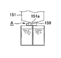
図3は洗浄装置の洗浄室151の下部に設けられた排液口151aからの洗浄液をその下方に配置された複数の洗浄液タンクから選択された洗浄液タンクに振り分けて供給し、その後順次他の洗浄液タンクに供給させる流路切替機構A付近のモデル断面図である。
FIG. 3 shows that a cleaning liquid from a
図中の151は洗浄室で、その排液口151aの直下に、洗浄液の流路切替機構Aを、取付用部材159を介して連結させている。そして、流路切替機構Aの下側には、直方体形をした4つの洗浄液タンク131〜134(以後、単にタンクと言う)を、排液口151aを取巻くようにして、田の字形に近接させた配置で設置している。この4つのタンクのうち、タンク131は、洗浄開始当初に排出されて、汚れ度合いが最もひどい洗浄液を、循環させずに溜めて置く貯留タンクとなる。
In the figure,
図3に示したように、流路切替機構Aは、洗浄室151の下面に固着された取付用部材159の平坦な底面に、連結ボルト190を用いて密着状態で取付けている。
As shown in FIG. 3, the flow path switching mechanism A is attached in close contact with the flat bottom surface of the
流路切替機構Aの概略の構成は、図3及び図4に示したように、排液口151aの周りに水平向きに回転自在で、排液口151aからの流出排液を、4つのタンク131〜134に、その液中の汚れ成分濃度が濃いタンクから薄いタンクの順に逐次流入させる役割を果たす回転分配盤101を、回転盤支持部材102の内空部に、回転自在に組込んでいる。回転盤支持部材102の側面には、回転分配盤101の駆動源となるモータ103を取付けている。
As shown in FIGS. 3 and 4, the schematic configuration of the flow path switching mechanism A is rotatable horizontally around the
回転分配盤101はこの例では金属又は合成樹脂製で、厚手の円盤状ブロックから成り、その上面中央部には、洗浄室151の排液口151aに摺接状態で連通させる、液入口104を開口させ、下面周縁部の1個所には、液出口105を設けている。そして、液入口104と液出口105とは、回転分配盤101を刳り抜くように設けた液流下路106を介して連通させている。
In this example, the
回転分配盤101の外周面には、リングギア107を嵌着させている。また、回転分配盤101の上面には、取付用部材159の平坦な下面に摺接する環状パッキン108を、液入口104を包囲する配置で設けている。
A ring gear 107 is fitted on the outer peripheral surface of the
回転盤支持部材102は、上半部102Aと下半部102Bとを、連結ボルト109により合体させた構成を備えている。回転分配盤101は、この上半部102Aに設けた内空部に内嵌させたベアリング110を介して、回転盤支持部材102に回動自在に支持されている。
The
環状ケーシング状の回転盤支持部材102の、上半部102Aの上面と、取付用部材159との当接面、及び上半部102Aの内周面と回転分配盤101の外周面との間に設けた環状空隙aには、夫々液密保持用の環状パッキン111及び112を配設している。
Between the upper surface of the
回転盤支持部材2の平面視形状は、図4に示したように、円形盤の外周面の1個所を膨出させた形態を備えており、この膨出個所をギアボックス部102Cとしている。ギアボックス部102Cの側端面には、可変速のモータ103を取付けている。
As shown in FIG. 4, the plan view shape of the turntable support member 2 has a form in which one portion of the outer peripheral surface of the circular plate is bulged, and this bulged portion is used as a
ギアボックス部102Cには、リングギア107に噛合するピニオン113のギア軸114を支承する、上下1組の軸受115,115を組込んでいる。ギア軸114には、ベベルギア116を軸嵌させている。このベベルギア116には、モータ103の出力軸117に軸嵌した別のベベルギア118が噛合される。
A pair of upper and
さらに、回転分配盤101の外周面には、4つのタンク131〜134の配置に対応した計4個所に、回転分配盤101の回転位置検知用の、回転位置表示部121を取付けている。一方、環状ケーシング状の回転盤支持部材102の下半部102Bの下面には、各回転位置表示部121に対応した夫々の位置に、回転位置センサ122を取付けている。
Further, on the outer peripheral surface of the
各回転位置センサ122は、図4に示したように、環状ケーシング状の回転盤支持部材102の周方向に沿って、変位可能な円弧状帯板123に取付けている。円弧状帯板123には、その円弧に沿う配置で長孔124を設けてある。そして、この長孔124に挿通させたボルト125を、環状ケーシング状の回転盤支持部材102の螺孔に螺止することによって、回転位置センサ122の固定位置を微調整可能にしている。
As shown in FIG. 4, each
流路切替機構Aには、上述のように、洗浄室151内の洗浄物品の洗浄過程で、排液口151aから排出させた洗浄排液を、複数のタンク131〜134に順次切替えて流入させるために、回転分配盤101の回転動を制御するモータ103の、回動制御部(図示略)を付属させている。
In the flow path switching mechanism A, as described above, the cleaning drainage discharged from the
流路切替機構Aは、図3から容易に理解されるように、その高さ寸法を、極力低く抑えられる構造になっている。その分、洗浄液循環濃縮システム全体の背丈をかなり低くすることができ、限られたスペースの設置場所にも、このシステムを無理なく納められるようになる。 As can be easily understood from FIG. 3, the flow path switching mechanism A has a structure in which the height dimension can be suppressed as low as possible. Accordingly, the overall height of the cleaning liquid circulation concentration system can be considerably reduced, and this system can be easily installed even in a limited space.
また、上記流路切替機構Aは、図3に示したように、その全体が完全な液密構造になっている。そのため、腐食性のある洗浄液を扱う場合でも、その保守・管理の為の手間と経費を殆ど省け、かつ、充分な耐久性を確保出来る。 Further, as shown in FIG. 3, the flow path switching mechanism A has a completely liquid-tight structure as a whole. Therefore, even when handling a corrosive cleaning liquid, the labor and cost for maintenance and management can be saved and sufficient durability can be ensured.
このような流路切替機構Aを備えている洗浄装置を用いることで、上記課題を解決することを見出し、本発明に至った。 The present inventors have found that the above-described problems can be solved by using a cleaning device including such a flow path switching mechanism A, and have reached the present invention.
すなわち、本発明の洗浄システムは、上記課題を解決するため、請求項1に記載の通り、シャワー式洗浄装置を備え、液相処理工程で処理された物品の洗浄を行う洗浄システムであり、前記シャワー式洗浄装置が、洗浄槽、該洗浄槽内部にシャワーノズル、該洗浄槽下部に排液口、該排液口の下流側に洗浄液貯液槽、及び、該洗浄液貯液槽内の洗浄液を前記シャワーノズルに接続された配管を経由して該シャワーノズルに循環供給する循環洗浄手段、を備えているシャワー式洗浄装置であって、
前記洗浄液貯液槽と該洗浄液貯液槽に接続された循環洗浄手段とからなる貯液槽・循環手段の組合せを複数備え、かつ、該複数の貯液槽・循環手段の組合せ中から1つの貯液槽・循環手段の組合せを選択して、該選択された洗浄液貯液槽にのみ前記排液口からの洗浄液を供給させるとともに、該選択された洗浄液貯液槽に接続された循環洗浄手段のみを稼働させて洗浄を行い、その後、順次他の貯液槽・循環手段の組合せに切替え、以後同様に繰り返す、組合せ選択手段を備えている洗浄装置であり、かつ、前記洗浄液貯液槽に容れられた洗浄液のうちの最初に用いられた洗浄液を前記液相処理工程での処理液として前記液相処理工程に送る洗浄液液相処理送液手段を備えていることを特徴とする洗浄システムである。
That is, in order to solve the above-mentioned problem, the cleaning system of the present invention is a cleaning system that includes a shower type cleaning device and performs cleaning of an article processed in the liquid phase processing step, as described in claim 1, The shower type cleaning device has a cleaning tank, a shower nozzle inside the cleaning tank, a drain port at the bottom of the cleaning tank, a cleaning liquid storage tank downstream of the draining port, and a cleaning liquid in the cleaning liquid storage tank. A circulating cleaning means that circulates and supplies the shower nozzle through a pipe connected to the shower nozzle.
A plurality of storage tank / circulation means combinations comprising the cleaning liquid storage tank and a circulation cleaning means connected to the cleaning liquid storage tank, and one of the plurality of storage tank / circulation means combinations; Select a combination of liquid storage tank and circulation means, supply the cleaning liquid from the drainage port only to the selected cleaning liquid storage tank, and circulating cleaning means connected to the selected cleaning liquid storage tank Is a cleaning device equipped with a combination selection means, which is sequentially switched to another liquid storage tank / circulation means combination, and thereafter repeated in the same manner, and the cleaning liquid storage tank A cleaning system comprising: a cleaning liquid phase treatment liquid feeding means for sending a cleaning liquid used first among the contained cleaning liquids to the liquid phase processing step as a processing liquid in the liquid phase processing step. is there.
また、本発明の洗浄システムは請求項2に記載の通り、請求項1に記載の洗浄システムにおいて、前記シャワー式洗浄装置の前記組合せ選択手段が前記切替の際に、前記循環洗浄手段を停止させた後に、前記シャワーノズル付近の前記配管中の洗浄液を該配管が接続された洗浄液貯液槽に逆送し、その後所定時間後に、次の貯液槽・循環手段の組合せに切替えるものであることを特徴とする。 Further, the cleaning system according to the present invention is the cleaning system according to claim 1, wherein the combination cleaning unit of the shower type cleaning device stops the circulation cleaning unit when the switching is performed. After that, the cleaning liquid in the pipe in the vicinity of the shower nozzle is sent back to the cleaning liquid storage tank to which the pipe is connected, and then, after a predetermined time, it is switched to the next storage tank / circulation means combination. It is characterized by.
また、本発明の洗浄システムは請求項3に記載の通り、請求項1または請求項2に記載の洗浄システムにおいて、前記シャワー式洗浄装置の前記洗浄液と接触する部分に、親水化処理、親水加工処理、撥水化処理、及び、撥水加工処理から選ばれる1つ以上の処理が施されていることを特徴とする。 Moreover, the cleaning system of the present invention is the cleaning system according to claim 1 or 2 according to claim 3, wherein the portion of the shower type cleaning device that comes into contact with the cleaning liquid is subjected to a hydrophilic treatment and a hydrophilic processing. One or more processes selected from a process, a water-repellent process, and a water-repellent process are performed.
また、本発明の洗浄システムは請求項4に記載の通り、請求項1ないし請求項3のいずれか1項に記載の洗浄システムにおいて、前記シャワー式洗浄装置が、前記循環洗浄手段を停止させた後に、前記洗浄槽、及び、被洗浄物に対して、液切りのために衝撃を付与する、衝撃付与手段を備えていることを特徴とする。 Moreover, the cleaning system according to the present invention is the cleaning system according to any one of claims 1 to 3, wherein the shower type cleaning device stops the circulating cleaning means. Later, it is provided with an impact applying means for applying an impact to the cleaning tank and the object to be cleaned for draining liquid.
また、本発明の洗浄システムは請求項5に記載の通り、請求項1ないし請求項4のいずれか1項に記載の洗浄システムにおいて、前記シャワー式洗浄装置が、前記複数の洗浄液貯液槽のうち1つの洗浄液貯液槽内の洗浄液を他所へ移送し排液した後に、該洗浄液が排液された洗浄液貯液槽に他の洗浄液貯液槽中の洗浄液を移送し、かつ、この洗浄液の移送及び排液を順次繰り返す洗浄液前送り手段と、最後に洗浄液の移送及び排液を行った洗浄液貯液槽に新たな洗浄液を導入する洗浄液導入手段と、を備えていることを特徴とする。 Moreover, the cleaning system according to the present invention is the cleaning system according to any one of claims 1 to 4, wherein the shower type cleaning device includes a plurality of cleaning liquid storage tanks. After the cleaning liquid in one of the cleaning liquid storage tanks is transferred to another place and drained, the cleaning liquid in the other cleaning liquid storage tank is transferred to the cleaning liquid storage tank from which the cleaning liquid has been drained, and the cleaning liquid A cleaning liquid pre-feeding means that sequentially repeats the transfer and drainage, and a cleaning liquid introduction means that introduces a new cleaning liquid into the cleaning liquid storage tank that finally transferred and drained the cleaning liquid.
また、本発明の洗浄システムは請求項6に記載の通り、請求項5に記載の洗浄システムにおいて、前記シャワー式洗浄装置で洗浄された物品をさらに洗浄するための最終洗浄槽と、該最終洗浄槽中の洗浄液を浄化するための精製手段と、を備え、かつ、前記洗浄液導入手段が、該最終洗浄槽内の洗浄液を前記新たな洗浄液として、前記最後に洗浄液の移送及び排液を行った洗浄液貯液槽に導入するものであることを特徴とする。 Moreover, the cleaning system of the present invention is the cleaning system according to claim 5, wherein the cleaning system according to claim 5 further includes a final cleaning tank for further cleaning the articles cleaned by the shower type cleaning device, and the final cleaning. Purification means for purifying the cleaning liquid in the tank, and the cleaning liquid introducing means used the cleaning liquid in the final cleaning tank as the new cleaning liquid, and finally transferred and discharged the cleaning liquid. It is introduced into the cleaning liquid storage tank.
また、本発明の洗浄システムは請求項7に記載の通り、請求項5または請求項6に記載の洗浄システムにおいて、前記複数の洗浄液貯液槽が、それぞれ直列に接続された2つ以上の貯液槽から構成され、これら貯液槽のそれぞれ最下流側の貯液槽がそれぞれ前記移送及び排液の順番に下から上に位置するように配置され、かつ、これら最下流側の貯液槽のうち下から2番目以降の貯液槽に重力を利用して一つ下に位置する貯液槽へそれぞれの洗浄液を移送及び排液するための配管と、該配管に設けられた開閉可能なバルブ装置と、を備えていることを特徴とする。 According to a seventh aspect of the present invention, there is provided a cleaning system according to the seventh aspect, wherein the plurality of cleaning liquid storage tanks are each connected in series with two or more storage tanks. Each of the storage tanks is arranged such that the storage tanks on the most downstream side of these storage tanks are positioned from bottom to top in the order of the transfer and drainage, respectively, and the storage tanks on the most downstream side A pipe for transferring and draining each cleaning liquid to a liquid storage tank located one level below by using gravity in the second and subsequent liquid storage tanks from below, and openable and closable provided in the pipe And a valve device.
また、本発明の洗浄システムは請求項8に記載の通り、請求項1ないし請求項4のいずれか1項に記載の洗浄システムにおいて、前記シャワー式洗浄装置の前記複数の洗浄液貯液槽がそれぞれ直列に接続された2つ以上の貯液槽から構成されていることを特徴とする。 Moreover, the cleaning system of the present invention is the cleaning system according to any one of claims 1 to 4, wherein the plurality of cleaning liquid storage tanks of the shower type cleaning device are respectively set as described in claim 8. It is composed of two or more liquid storage tanks connected in series.
また、本発明の洗浄システムは請求項9に記載の通り、請求項1ないし請求項8のいずれか1項に記載の洗浄システムにおいて、上記シャワー式洗浄装置による洗浄の前に液相処理工程で処理された物品の洗浄を行うための回収槽を備え、前記洗浄液液相処理送液手段が、前記シャワー式洗浄装置からの前記最初に用いられた洗浄液を回収液として該回収槽に供給し、かつ、該回収槽内の回収液を前記液相処理工程での処理液として前記液相処理工程に送るものであることを特徴とする。 The cleaning system according to the present invention is the cleaning system according to any one of claims 1 to 8, wherein the cleaning system according to the present invention is a liquid phase treatment step prior to cleaning by the shower type cleaning device. A recovery tank for cleaning the treated article, the cleaning liquid phase processing liquid feeding means supplies the first used cleaning liquid from the shower type cleaning device to the recovery tank as a recovery liquid; And the collection | recovery liquid in this collection tank is sent to the said liquid phase processing process as a processing liquid in the said liquid phase processing process, It is characterized by the above-mentioned.
また、本発明の洗浄システムは請求項10に記載の通り、請求項1ないし請求項9のいずれか1項に記載の洗浄システムにおいて、前記洗浄液液相処理送液手段が、前記シャワー式洗浄装置から前記液相処理工程へ至る経路に、該径路によって送液される被送液を濃縮する洗浄液濃縮手段、及び/あるいは、該径路によって送液される被送液を精製するための洗浄液精製手段を備えている。 The cleaning system according to the present invention is the cleaning system according to any one of claims 1 to 9, wherein the cleaning liquid phase treatment liquid feeding means is the shower type cleaning device. Cleaning liquid concentrating means for concentrating the liquid to be fed sent by the path to the path from the liquid phase treatment step to the liquid phase treatment step, and / or cleaning liquid purifying means for purifying the liquid to be fed sent by the path It has.
本発明の洗浄システムによれば、環境負担の生じないクローズドシステムでの欠点であった、装置規模が大型になり、これらの装置類の占有面積が大きくなると云う問題を解決することができる、洗浄効果の高い洗浄システムとなる。 According to the cleaning system of the present invention, it is possible to solve the problem that the scale of the apparatus is large and the occupied area of these apparatuses is large, which is a disadvantage of the closed system that does not cause an environmental burden. It becomes a highly effective cleaning system.
さらに前記シャワー式洗浄装置の前記組合せ選択手段が前記切替の際に、前記循環洗浄手段を停止させた後に、前記シャワーノズル付近の前記配管中の洗浄液を該配管が接続された洗浄液貯液槽に逆送し、その後所定時間後に、次の貯液槽・循環手段の組合せに切替えるものであることにより、シャワーノズルからの洗浄液(要洗浄成分濃度が濃い)の液だれをなくすることができ、次の貯液槽・循環手段の組合せに切替えたときの、前の洗浄液の持ち込みが少なくなるために洗浄効果が高くなり、コンパクトで、少ない洗浄液の液量でありながら、従来の洗浄システムに匹敵する効果の高い洗浄が可能な洗浄システムとなる。 Furthermore, after the combination selection unit of the shower type cleaning device stops the circulating cleaning unit when the switching is performed, the cleaning liquid in the pipe near the shower nozzle is transferred to a cleaning liquid storage tank to which the pipe is connected. By reversely feeding, and then switching to the next storage tank / circulation means combination after a predetermined time, it is possible to eliminate the dripping of the cleaning liquid from the shower nozzle (concentration of required cleaning component is high), When switching to the next storage tank / circulation unit combination, the amount of cleaning solution brought in before is reduced, so the cleaning effect is enhanced, and it is compact and has a small amount of cleaning solution, but comparable to conventional cleaning systems. Therefore, the cleaning system can perform cleaning with a high effect.
また、本発明の洗浄システムは、前記シャワー式洗浄装置の前記洗浄液と接触する部分に、親水化処理、親水加工処理、撥水化処理、及び、撥水加工処理から選ばれる1つ以上の処理が施されているために、液切れが良好であるために、次の貯液槽・循環手段の組合せに切替えたときの、前の洗浄液の持ち込みが少なくなるために洗浄効果が高い。 In the cleaning system of the present invention, at least one treatment selected from a hydrophilic treatment, a hydrophilic processing treatment, a water repellency treatment, and a water repellency treatment treatment is performed on the portion of the shower type cleaning device that comes into contact with the cleaning liquid. Therefore, since the drainage of the liquid is good, the previous cleaning liquid brought in when switching to the next storage tank / circulation means combination is reduced, and the cleaning effect is high.
また、本発明の洗浄システムは、前記循環洗浄手段を停止させた後に、前記洗浄槽、及び、被洗浄物に対して、液切りのために衝撃を付与する、衝撃付与手段を備えていることにより、より効果的に液残りを防止することができるので、高い洗浄効果が得られる。 In addition, the cleaning system of the present invention includes an impact applying unit that applies an impact to the cleaning tank and an object to be cleaned for draining the liquid after the circulating cleaning unit is stopped. As a result, liquid residue can be prevented more effectively, and a high cleaning effect can be obtained.
また、本発明の洗浄システムは、前記複数の洗浄液貯液槽のうち1つの洗浄液貯液槽内の洗浄液を他所へ移送し排液した後に、該洗浄液が排液された洗浄液貯液槽に他の洗浄液貯液槽中の洗浄液を移送し、かつ、この洗浄液の移送及び排液を順次繰り返す洗浄液前送り手段と、最後に洗浄液の移送及び排液を行った洗浄液貯液槽に新たな洗浄液を導入する洗浄液導入手段と、を備えているので、洗浄液を効率的に利用することができ、濃縮、濾過、精製処理などの処理コストを低く抑えることができる。 In addition, the cleaning system of the present invention includes a cleaning liquid storage tank in which the cleaning liquid is discharged after the cleaning liquid in one cleaning liquid storage tank is transferred to another place and drained. The cleaning liquid in the cleaning liquid storage tank is transferred, and the cleaning liquid pre-feeding means that sequentially repeats the transfer and drainage of the cleaning liquid, and the cleaning liquid storage tank that has finally transferred and discharged the cleaning liquid, Since the cleaning liquid introducing means is provided, the cleaning liquid can be used efficiently, and processing costs such as concentration, filtration, and purification can be kept low.
また、本発明の洗浄システムは、前記シャワー式洗浄装置で洗浄された物品をさらに洗浄するための最終洗浄槽を備え、かつ、前記洗浄液導入手段が、該最終洗浄槽内の洗浄液を前記最後に洗浄液の移送及び排液を行った洗浄液貯液槽に新たな洗浄液を導入するものであると、シャワー式洗浄装置では洗浄されにくい複雑形状の物品であっても確実に洗浄できるとともに、最終洗浄槽の洗浄液、及び、その中に含有される被洗浄成分を有効利用することができる。 The cleaning system of the present invention further includes a final cleaning tank for further cleaning the articles cleaned by the shower type cleaning device, and the cleaning liquid introduction means supplies the cleaning liquid in the final cleaning tank to the last. By introducing a new cleaning liquid into the cleaning liquid storage tank where the cleaning liquid has been transferred and drained, it is possible to reliably clean even complex shaped articles that are difficult to be cleaned by the shower type cleaning device, and the final cleaning tank. The cleaning liquid and the components to be cleaned contained therein can be effectively used.
また、本発明の洗浄システムは、前記シャワー式洗浄装置で洗浄された物品をさらに洗浄するための最終洗浄槽と、該最終洗浄槽中の洗浄液を浄化するための精製手段と、を備え、かつ、前記洗浄液導入手段が、該最終洗浄槽内の洗浄液を前記新たな洗浄液として、前記最後に洗浄液の移送及び排液を行った洗浄液貯液槽に導入するものであると、シャワー洗浄では落とせなかった部分も充分な洗浄が可能となるのと同時に、前記洗浄装置に清澄な洗浄液を供給することが可能となる。 The cleaning system of the present invention further comprises a final cleaning tank for further cleaning the articles cleaned by the shower type cleaning device, and a purification means for purifying the cleaning liquid in the final cleaning tank, and If the cleaning liquid introduction means introduces the cleaning liquid in the final cleaning tank as the new cleaning liquid into the cleaning liquid storage tank that has transferred and drained the cleaning liquid at the end, it cannot be removed by shower cleaning. As a result, it becomes possible to supply a clear cleaning solution to the cleaning device.
また、本発明の洗浄システムは、前記複数の洗浄液貯液槽がそれぞれ直列に接続された2つ以上の貯液槽から構成されていることにより、洗浄槽の下に置く貯液槽の容量が小さくても充分な洗浄液量が確保でき、また、装置の高さを低く抑えることができ、例えばめっき処理を含む処理装置などへの組み込みが容易となり、応用範囲を広くすることができる。 In the cleaning system of the present invention, the plurality of cleaning liquid storage tanks are each composed of two or more storage tanks connected in series, so that the capacity of the liquid storage tank placed under the cleaning tank is reduced. Even if it is small, a sufficient amount of cleaning liquid can be secured, and the height of the apparatus can be kept low. For example, it can be easily incorporated into a processing apparatus including a plating process, and the application range can be widened.
また、本発明の洗浄システムは、前記複数の洗浄液貯液槽がそれぞれ直列に接続された2つ以上の貯液槽から構成され、これら貯液槽のそれぞれ最下流側の貯液槽がそれぞれ前記移送及び排液の順番に下から上に位置するように配置され、かつ、これら最下流側の貯液槽のうち下から2番目以降の貯液槽に重力を利用して一つ下に位置する貯液槽へそれぞれの洗浄液を移送及び排液するための配管と、該配管に設けられた開閉可能なバルブ装置とを備えているので、洗浄槽の下に置く貯液槽の容量が小さくても充分な洗浄液量が確保でき、また、装置の高さを低く抑えることができ、例えばめっき処理を含む処理装置などへの組み込みが容易となり、応用範囲を広くすることができるとともに、基本的にはバルブ操作だけで洗浄液の移送及び排液が可能となるので、装置コストを低廉に抑えることが可能となる。さらに、洗浄槽付近に洗浄液の送液を行うポンプ類や制御機器を配置する必要がなくなり、例えば洗浄槽から離れたところにこれら貯液槽のそれぞれ最下流側の貯液槽を配置すると共にその付近にポンプを集約配置することが可能となるので、例えば、表面処理ラインにおける従来の洗浄装置との置き換えが容易となると共に、洗浄装置の洗浄槽付近での作業性の悪化を防止することができる。 Further, the cleaning system of the present invention is composed of two or more storage tanks in which the plurality of cleaning liquid storage tanks are connected in series, and each of the storage tanks on the most downstream side of each of the storage tanks is the above-described storage tank. It is arranged so that it is located from the bottom to the top in the order of transfer and drainage, and one of the most downstream side reservoirs is located one lower by gravity using the second and subsequent reservoirs from the bottom Since the pipe for transferring and draining each cleaning liquid to and from the storage tank and the openable and closable valve device provided in the pipe are provided, the capacity of the storage tank placed under the cleaning tank is small. However, a sufficient amount of cleaning solution can be secured, and the height of the apparatus can be kept low. For example, it can be easily incorporated into a processing apparatus including a plating process, and the application range can be widened. In order to transfer the cleaning liquid and to Since the liquid is possible, it is possible to suppress equipment cost as low cost. Furthermore, there is no need to arrange pumps or control devices for supplying the cleaning liquid near the cleaning tank. For example, the storage tanks at the most downstream side of these storage tanks are arranged at locations away from the cleaning tank. Since it is possible to centrally arrange the pumps in the vicinity, for example, it is easy to replace the conventional cleaning device in the surface treatment line, and it is possible to prevent deterioration of workability in the vicinity of the cleaning tank of the cleaning device. it can.
また、本発明の洗浄システムは、上記シャワー式洗浄装置による洗浄の前に液相処理工程で処理された物品の洗浄を行うための回収槽を備え、前記洗浄液液相処理送液手段が、前記シャワー式洗浄装置からの前記最初に用いられた洗浄液を回収液として該回収槽に供給し、かつ、該回収槽内の回収液を前記液相処理工程での処理液として前記液相処理工程に送るものであるとさらに効果の高い洗浄が可能となる。 Further, the cleaning system of the present invention includes a recovery tank for cleaning the article processed in the liquid phase processing step before cleaning by the shower type cleaning device, and the cleaning liquid phase processing liquid feeding means includes the The first used cleaning liquid from the shower type cleaning device is supplied to the recovery tank as a recovery liquid, and the recovery liquid in the recovery tank is supplied to the liquid phase processing process as a processing liquid in the liquid phase processing process. If it is to be sent, more effective cleaning is possible.
また、本発明の洗浄システムは、前記洗浄液液相処理送液手段が、前記シャワー式洗浄装置から前記液相処理工程へ至る経路に、該径路によって送液される被送液を濃縮する洗浄液濃縮手段を備えていることにより、前記液相処理工程での処理液の濃度の低下を防ぎながら、かつ、最も被洗浄成分の高い洗浄液であっても液相処理工程での処理液での成分に比して低い濃度段階での液相処理工程への送液(あるいは回収槽への送液)ができるので、洗浄効果を高く維持することができる。また、前記シャワー式洗浄装置から前記液相処理工程へ至る経路に、該径路によって送液される被送液を精製するための洗浄液精製手段洗浄液精製手段を備えたものであると、不純物、異物の液相処理工程への混入による蓄積による障害・事故発生を未然に防止することができ、特に洗浄液濃縮手段と組み合わせてその下流側に配することで特に高い効果が得られる。 In the cleaning system of the present invention, the cleaning liquid concentration processing liquid supply means concentrates the liquid to be transferred sent by the path to the path from the shower type cleaning device to the liquid phase processing step. By providing the means, while preventing a decrease in the concentration of the processing liquid in the liquid phase processing step, and even in the cleaning liquid with the highest component to be cleaned, the component in the processing liquid in the liquid phase processing step Since the liquid can be sent to the liquid phase treatment step (or the liquid is sent to the recovery tank) at a lower concentration stage, the cleaning effect can be kept high. Further, in the path from the shower type cleaning apparatus to the liquid phase treatment step, a cleaning liquid purifying means for purifying a liquid to be fed sent by the path, a cleaning liquid purifying means, impurities, foreign matters Occurrence of troubles and accidents due to accumulation due to contamination in the liquid phase treatment process can be prevented in advance, and in particular, a particularly high effect can be obtained by disposing it in combination with the cleaning liquid concentration means.
図1に本発明に係る洗浄システムの一例をめっき装置Bに、めっきされた物品の洗浄処理システムとして組み込んだ、洗浄処理システム付近の槽配置をモデル的に示す。 FIG. 1 schematically shows a tank arrangement in the vicinity of a cleaning processing system in which an example of a cleaning system according to the present invention is incorporated in a plating apparatus B as a cleaning processing system for plated articles.
めっき浴槽20、回収槽21、洗浄装置αの洗浄槽1(後述する)、及び、最終洗浄槽22がこの順に配置されている。
A plating
この例ではめっき浴槽20で電気めっきされた物品は図示しないハンガーごと、めっき浴槽20から引き上げられ、回収槽21の上方に移動された後、降下され、回収槽21内の回収液に浸漬され、再度引き上げられた後、洗浄装置αの洗浄槽1の上方へ移動された後、降下され、洗浄装置αの洗浄槽1で後述するように洗浄される。次いで、最終洗浄槽22上方へ移動された後、降下され、最終洗浄槽22で最終洗浄され、その後、次の処理工程、例えば、例えば乾燥工程に進む。
In this example, the article electroplated in the
この最終洗浄槽22には最終洗浄槽中の洗浄液を浄化するための精製手段としてイオン交換樹脂塔24、ポンプ23及び配管が付属し、最終洗浄槽22の洗浄液は、ポンプ23によりイオン交換樹脂塔24に供給されて洗浄液中の金属イオン及び硫酸イオンなどの陰イオンが除去された後、配管24aにより再度最終洗浄槽22に戻るように循環されている。このとき、分岐配管12により最終洗浄槽22の洗浄液は、後述するように洗浄装置αの貯液槽7dに供給されるようになっている。また、最終洗浄槽22には供給ライン27から新たな洗浄液が供給されることにより最終洗浄槽22内の液位は一定に保たれる。この例では供給ライン27から水道水が供給されるが、上記のように最終洗浄槽22には精製手段が設けられているので、最終洗浄槽22内の洗浄液は常に良好な状態に保たれている。
The
ここで、最終洗浄槽中の洗浄液を浄化するための精製手段としては上記イオン交換樹脂塔24の他に、あるいは、イオン交換樹脂塔24の代わりに逆浸透膜などの精密濾過器を備えていても良い。
Here, as a purification means for purifying the cleaning liquid in the final cleaning tank, a precision filter such as a reverse osmosis membrane is provided in addition to the ion
一方、後述する洗浄装置αの貯液槽7a、7b、7c、及び、7dはこの順に下から上に位置するように、ただし、上記めっき装置Bの各種槽によるラインとは別の場所に、上記ラックによって保持されている。
On the other hand, the
このうち貯液槽7aの底部の配管7a1はポンプ25aによって洗浄液濃縮手段としての濃縮装置25に供給されて適当な濃度となるように濃縮後、洗浄液精製手段としての濾過装置26によって濾過されて各種浮遊物、ゴミなどが除去された後、配管26aによって、液相処理工程での処理液としてのめっき浴槽20内のめっき浴液として、前記液相処理工程のめっき浴槽に送られる。
Of these, the pipe 7a1 at the bottom of the
なお、上記例では洗浄液精製手段として、濾過装置26を設けたが、濾過装置の代わりに、あるいは、濾過装置に併用して、活性炭塔を設けても良い。
In the above example, the
次いで、図2(a)及び図2(b)に洗浄装置αのモデル図を示す。 Next, FIGS. 2A and 2B are model diagrams of the cleaning apparatus α.
図2(a)は正面から見た、正面に近い箇所でのモデル断面図であり、図2(b)は裏面から見た、裏面に近い箇所でのモデル断面図である。 2A is a model cross-sectional view at a location near the front as seen from the front, and FIG. 2B is a model cross-sectional view at a location near the back as seen from the back.
この洗浄装置αは、洗浄槽1、洗浄槽1内部にシャワーノズル1a、1b、1c、及び、1dがそれぞれ複数個、洗浄槽1下部に排液口1f、排液口1fの下流側に洗浄液貯液槽、及び、洗浄液貯液槽内の洗浄液をシャワーノズル1a、1b、1c、及び、1dに接続された配管を経由してシャワーノズル1a、1b、1c、及び、1dに循環供給する循環洗浄手段、を備えている洗浄装置であって、洗浄液貯液槽と洗浄液貯液槽に接続された循環洗浄手段とからなる貯液槽・循環手段の組合せを複数備えている。
The cleaning apparatus α has a plurality of
すなわち、シャワーノズル1a、1b、1c、及び、1dにはそれぞれ配管1a1、1b1、1c1、及び、1d1などの配管を介してそれぞれポンプ2a−洗浄槽下受液槽4a−ポンプ3a−貯液槽7a−ポンプ2aの組合せ、ポンプ2b−洗浄槽下受液槽4b−ポンプ3b−貯液槽7b−ポンプ2bの組合せ、ポンプ2c−洗浄槽下受液槽4c−ポンプ3c−貯液槽7c−ポンプ2cの組合せ、及び、ポンプ2d−洗浄槽下受液槽4d−ポンプ3d−貯液槽7d−ポンプ2dの組合せが接続されている。これらの内、洗浄槽下受液槽4a〜4d及び貯液槽7a〜7dは洗浄液貯液槽を構成し、ポンプ2a、2b、2c及び2d、ポンプ3a、3b、3c及び3d及び配管類は循環洗浄手段である。
That is, the
ここで、このように、それぞれの組合せで貯液槽がそれぞれ直列に接続された、洗浄槽下受液槽4aと貯液槽7aとから、洗浄槽下受液槽4bと貯液槽7bとから、洗浄槽下受液槽4cと貯液槽7cとから、及び、洗浄槽下受液槽4dと貯液槽7dとから、構成されているために、各洗浄液の液量が多くても、洗浄槽下受液槽の高さを低く、かつ大きさを小さくすることが可能であるので、洗浄槽の下に置く貯液槽の容量が小さくても充分な洗浄液量が確保でき、また、装置の高さを低く抑えることができ、例えばめっき処理を含む処理装置などへの組み込みが容易となり、応用範囲を広くすることができる。
Here, the washing tank lower
さらにこれら直列に接続された貯液槽のうち、最下流側の貯液槽である貯液槽7a、貯液槽7b、貯液槽7c、及び、貯液槽7dは後述する移送及び排液の順番に、下から上に位置するように配置されている。
Further, among the storage tanks connected in series, the
さらに、この洗浄装置αは、複数の貯液槽・循環手段の組合せ中から1つの貯液槽・循環手段の組合せを選択して、該選択された洗浄液貯液槽にのみ前記排液口からの洗浄液を供給させるとともに、該選択された洗浄液貯液槽に接続された循環洗浄手段のみを稼働させて洗浄を行い、その後、順次他の貯液槽・循環手段の組合せに切替え、以後同様に繰り返す、図示しない、組合せ選択手段を有するが、このような組合せ選択手段は洗浄槽1の排液口1f直下に設けられた、特開2001−347235公報記載の技術に係る流路切替機構A、各ポンプ2a〜2d、及び、ポンプ3a〜3dを制御する。
Further, the cleaning device α selects one liquid storage tank / circulation means combination from a combination of a plurality of liquid storage tanks / circulation means, and allows only the selected cleaning liquid storage tank from the drain port. The cleaning liquid is supplied, and only the circulating cleaning means connected to the selected cleaning liquid storage tank is operated to perform cleaning, and then sequentially switched to another liquid storage tank / circulation means combination. Repeatedly, there is a combination selection means (not shown), but such a combination selection means is provided immediately below the drainage port 1f of the cleaning tank 1, and the flow path switching mechanism A according to the technique described in JP-A-2001-347235, Each
さらに、この組合せ選択手段は切替の際に、循環洗浄手段のポンプ2a〜2d及びポンプ3a〜3dを停止させた後に、シャワーノズル1a、1b、1c、及び、1d付近の配管中の洗浄液を配管が接続された洗浄液貯液槽である洗浄槽下受液槽4a〜4dに逆送し、その後所定時間後に、次の貯液槽・循環手段の組合せに切替えるものであり、配管1a1、1b1、1c1、及び、1d1のそれぞれの洗浄槽下受液槽4a、4b、4c、及び、4dの上縁よりも高い位置で、かつ、すべてのシャワーノズル1a、1b、1c、及び、1dよりも低い位置で分岐され、それぞれこれら洗浄槽下受液槽内へ導かれている分岐配管6a、6b、6c、及び、6dのそれぞれに設けられたバルブ5a、5b、5c、及び、5dをそれぞれ制御するものである。
Further, when the combination selection unit is switched, the
ここで、このような組合せ選択手段はタイマー装置及び各種リレー装置、あるいはマイクロコンピュータ(必要に応じ各種リレー装置を併用)から構成することができるが、動作仕様の保守や変更、追加等の容易さからマイクロコンピュータを用いることが好ましく、洗浄装置αにおける組合せ選択手段はマイクロコンピュータを用いるものとなっていて、後述する各種制御機構も兼ねるものとなっている。 Here, such a combination selection means can be composed of a timer device and various relay devices, or a microcomputer (a combination of various relay devices as required), but it is easy to maintain, change, add operation specifications, etc. It is preferable to use a microcomputer, and the combination selection means in the cleaning apparatus α uses a microcomputer, and also serves as various control mechanisms described later.
このような洗浄装置αにおいて、洗浄液と接触する部分に、親水化処理、親水加工処理、撥水化処理、及び、撥水加工処理から選ばれる1つ以上の処理が施されていると、排液が容易になると共に残留液が少なくなるので後工程での洗浄水への混入が少なくなり、高い洗浄効果が得られる。 In such a cleaning apparatus α, if one or more processes selected from a hydrophilic process, a hydrophilic process, a water repellent process, and a water repellent process are performed on a portion in contact with the cleaning liquid, Since the liquid becomes easy and the residual liquid is reduced, mixing into the cleaning water in the subsequent process is reduced, and a high cleaning effect is obtained.
このような親水化加工処理、親水化処理としては、洗浄装置αの洗浄槽1や配管などに使われる樹脂であるポリプロピレン樹脂あるいは塩化ビニル樹脂に対して親水性を有するポリビニルアルコールフィルム(日本合成化学社製等)を貼る親水化加工、あるいはチタニア、シリカ、シリコンからなる親水処理剤(TOTO社製等)で処理する親水化処理などが挙げられる。 As such hydrophilization processing and hydrophilization treatment, a polyvinyl alcohol film having a hydrophilic property to polypropylene resin or vinyl chloride resin, which is a resin used in the cleaning tank 1 and piping of the cleaning apparatus α (Nippon Synthetic Chemical) And the like, or a hydrophilic treatment in which treatment is performed with a hydrophilic treatment agent composed of titania, silica, silicon (TOTO, etc.).
また、撥水化加工処理、撥水化処理としては、洗浄装置αの洗浄槽1や配管などに使われる上記樹脂に対して、シリコーン樹脂系塗料(NTTアドバンステクノロジー社製等)や疎水性シリカ撥水剤(日華化学社製等)を塗布したり、あるいは、フッ素コーティング剤(フロロテクノロジー社製等)による表面処理を行う。 In addition, for the water repellent treatment and water repellent treatment, a silicone resin paint (manufactured by NTT Advanced Technology Co., Ltd.) or hydrophobic silica is used for the resin used in the cleaning tank 1 and piping of the cleaning device α. A water repellent (Nikka Chemical Co., Ltd.) is applied, or surface treatment is performed with a fluorine coating agent (Fluoro Technology Co., Ltd.).
この例では、洗浄槽1の内面には親水化加工としてポリビニルアルコールフィルム(日本合成化学社製等)を貼付してあり、凹凸によりフィルム貼付が困難な箇所にはNTTアドバンステクノロジー社製のシリコーン樹脂系塗料が塗布されて、撥水加工されている。 In this example, a polyvinyl alcohol film (manufactured by Nippon Synthetic Chemical Co., Ltd.) is pasted on the inner surface of the cleaning tank 1 as a hydrophilic treatment, and a silicone resin made by NTT Advanced Technology Co., Ltd. is used in places where film sticking is difficult due to unevenness. A water-repellent finish is applied with a paint.
さらに、このような洗浄装置αにおいて、循環洗浄手段を停止させた後に、洗浄槽1、及び、被洗浄物に対して、液切りのために衝撃を付与する、衝撃付与手段を備えていると、残留液が少なくなるので後工程での洗浄水への混入が少なくなり、高い洗浄効果が得られる。 Furthermore, in such a cleaning apparatus α, after stopping the circulation cleaning means, the cleaning tank 1 and the object to be cleaned are provided with an impact applying means for applying an impact for draining the liquid. Since the residual liquid is reduced, mixing into the cleaning water in the subsequent process is reduced, and a high cleaning effect is obtained.
このような衝撃付与手段としては各種アクチュエータ、あるいは各種アクチュエータとハンマーとを組み合わせて、構成することができる。 Such an impact applying means can be constituted by various actuators or a combination of various actuators and a hammer.
洗浄装置αでは洗浄槽1に衝撃を与える衝撃付与手段として、アクチュエータ(図示しない)とハンマーとを組み合わせたハンマー装置8aを洗浄槽1上縁付近に、被洗浄物であるめっき処理済み品10が多数架けられたハンガー11を介してめっき処理済み品10に対して衝撃を与える衝撃付与手段としてアクチュエータ(図示しない)とハンマーとを組み合わせたハンマー装置8bを洗浄槽1上方のハンガー11停止位置に、それぞれ備えている。
In the cleaning device α, a
また、洗浄装置αの複数の洗浄液貯液槽のうち1つの洗浄液貯液槽内の洗浄液を他所へ移送し排液した後に、該洗浄液が排液された洗浄液貯液槽に他の洗浄液貯液槽中の洗浄液を移送し、かつ、この洗浄液の移送及び排液を順次繰り返す洗浄液前送り手段と、最後に洗浄液の移送及び排液を行った洗浄液貯液槽に新しい洗浄液を導入する洗浄液導入手段とを備えていると、洗浄液を有効に用いることができ、その後処理(濃縮処理、イオン交換処理等)での負担を少なくすることができるので、洗浄装置αを用いる表面処理システム等のシステムのランニングコストを低廉なものとすることができると共に、必要な後処理の装置の小型化や低廉化も可能となる。 Further, after the cleaning liquid in one cleaning liquid storage tank among the plurality of cleaning liquid storage tanks of the cleaning apparatus α is transferred to a different place and drained, another cleaning liquid storage liquid is stored in the cleaning liquid storage tank from which the cleaning liquid has been drained. Cleaning liquid pre-feeding means for transferring the cleaning liquid in the tank and repeating the transfer and draining of the cleaning liquid in sequence, and cleaning liquid introducing means for introducing a new cleaning liquid into the cleaning liquid storage tank that has finally transferred and discharged the cleaning liquid. Since the cleaning liquid can be used effectively and the burden on the subsequent processing (concentration processing, ion exchange processing, etc.) can be reduced, the surface processing system using the cleaning apparatus α can be reduced. The running cost can be reduced, and the required post-processing apparatus can be reduced in size and cost.
この洗浄装置αはこのような洗浄液前送り手段としては、貯液槽7aの底部に設けられた配管7a1に接続されたバルブ7a2、バルブ7a2からの配管に接続された、濃縮装置25、濃縮装置25下流側に設けられた濾過装置26、及び、濾過装置26からめっき浴槽20上方に導かれた配管26aによってめっき浴槽20のめっき浴として、貯液槽7a内の洗浄液を送液するポンプ25a(これらバルブ7a2、ポンプ25a、配管、濃縮装置及び濾過装置は洗浄液液相処理送液手段を構成する)、貯液槽7bの底部であるとともに貯液槽7aへ導かれるように設けられた配管7b1に設けられたバルブ7b2、貯液槽7cの底部であるとともに貯液槽7bへ導かれるように設けられた配管7c1に設けられたバルブ7c2、及び、貯液槽7dの底部であるとともに貯液槽7cへ導かれるように設けられた配管7d1に設けられたバルブ7d2を制御する。
This cleaning device α is used as such a cleaning liquid forward feeding means as a valve 7a2 connected to a pipe 7a1 provided at the bottom of the
ここで、バルブ7b2を操作して開くことにより貯液槽7b内の洗浄液は、重力により貯液槽7aへ、バルブ7c2を操作して開くことにより貯液槽7c内の洗浄液は、重力により貯液槽7bへ、さらに、バルブ7d2を操作して開くことにより貯液槽7d内の洗浄液は、重力により貯液槽7cへ、移送及び排液可能となっているので、ポンプなどの高価な機材が不要であり、装置自体もコンパクトなものとなる。
When the valve 7b2 is operated and opened, the cleaning liquid in the
また、洗浄液導入手段は、貯液槽7dへ導かれるように設けられ、貯液槽7dに新しい洗浄液を導入するための配管12に設けられたバルブ12aを制御するものである。
The cleaning liquid introduction means is provided so as to be guided to the
洗浄液液相処理送液手段、これら洗浄液前送り手段、及び、洗浄液導入手段はタイマー装置及び各種リレー装置、あるいはマイクロコンピュータ(必要に応じ各種リレー装置を併用)から構成することができるが、動作仕様の保守や変更、追加等の容易さからマイクロコンピュータを用いることが好ましく、この洗浄装置αにおける洗浄液液相処理送液手段、洗浄液前送り手段、及び、洗浄液導入手段は上述の組合せ選択手段を構成するマイクロコンピュータが兼用している。 The cleaning liquid phase processing liquid feeding means, the cleaning liquid pre-feeding means, and the cleaning liquid introducing means can be composed of a timer device and various relay devices, or a microcomputer (a combination of various relay devices as required). It is preferable to use a microcomputer from the viewpoint of ease of maintenance, change, addition, etc., and the cleaning liquid phase processing liquid feeding means, the cleaning liquid pre-feeding means, and the cleaning liquid introducing means in the cleaning device α constitute the combination selecting means described above. The microcomputer to be used is also used.
次に、このような洗浄装置αによる洗浄について説明をする(この例ではすべてのポンプは停止し、すべてのバルブは閉まっている状態で、ただし、流路切替機構Aは排液口1fからの洗浄液が洗浄槽下受液槽4a上方に設けられた配管Aaへと流れる状態から開始する)。
Next, cleaning by such a cleaning apparatus α will be described (in this example, all pumps are stopped and all valves are closed, however, the flow path switching mechanism A is connected to the drain port 1f. The cleaning liquid starts from a state of flowing into the pipe Aa provided above the cleaning tank lower
洗浄槽1には、めっき工程、めっき液回収工程を経て、被洗浄物であるめっき処理済み品10が多数架けられたハンガー11が搬入され、図2(a)に示すハンガー11停止位置で停止する。
The washing tank 1 is loaded with a
ポンプ2a及びポンプ3aが稼働され、貯液槽7a内の洗浄液がポンプ2aにより配管1a1を通じてシャワーノズル1aにより、めっき処理済み品10に噴射され、めっき処理済み品10を洗浄した後、排液口1fから流路切替機構Aによって配管Aaを経て、洗浄槽下受液槽4aへと流れる。洗浄槽下受液槽4aに受けられた洗浄液は、洗浄槽下受液槽4a底部に設けられた配管とポンプ3aとにより、再び貯液槽7aに戻り、以下同様に循環する。この例では、ポンプ3aの容量は洗浄槽下受液槽4aへの洗浄液の供給量よりも大きいために、洗浄槽下受液槽4aの容量は小さいものであっても充分である。
The
貯液槽7a内の洗浄液による洗浄処理が、予め定められた時間(組合せ選択手段内のマイクロコンピュータのタイマーによる)、あるいは、予め定められた流量(図示しない流量計による測定結果による)、あるいは、洗浄液の各パラメータの分析結果(図示しない分析装置による)により、終了条件に達したときに、組合せ選択手段は循環洗浄手段としてのポンプ2aを止め、これによりシャワーノズル1aへの洗浄液の供給が止まると共に、組合せ選択手段はバルブ5aを開く。これにより、シャワーノズル1a付近の配管1a1中の洗浄液は配管が接続された洗浄液貯液槽である洗浄槽下受液槽4aに分岐配管6aを経て逆送される。
The cleaning process with the cleaning liquid in the
さらに衝撃付与手段であるハンマー装置8a及びハンマー装置8bが稼働して、洗浄槽1、及び、めっき処理済み品10が多数架けられたハンガー11に衝撃を与えて、洗浄槽1、めっき処理済み品10及びハンガー11に付着した洗浄液が落下し、洗浄槽下受液槽4aに回収される。
Further, the
このように洗浄槽下受液槽4aに逆送あるいは回収された洗浄液はポンプ3aによって貯液槽7aに回収される。これら回収・逆送される洗浄液がなくなった時間(この例では予め測定し組合せ選択手段に設定してある)後、組合せ選択手段は、バルブ5aを閉め、ポンプ3aを停止させると共に、次の貯液槽・循環手段を選択し、それを稼働させる。
The cleaning liquid that has been sent back or recovered to the lower tank receiving
すなわち、組合せ選択手段は流路切替機構Aを制御して、排液口1fからの洗浄液が洗浄槽下受液槽4b上方に設けられた配管Abへと流れる状態とする。
That is, the combination selection unit controls the flow path switching mechanism A so that the cleaning liquid from the drain port 1f flows into the pipe Ab provided above the cleaning tank lower
次いでポンプ2b及びポンプ3bが稼働され、貯液槽7b内の洗浄液がポンプ2bにより配管1b1を通じてシャワーノズル1bにより、めっき処理済み品10に噴射され、めっき処理済み品10を洗浄した後、排液口1fから流路切替機構Aによって配管Abを経て、洗浄槽下受液槽4bへと流れる。洗浄槽下受液槽4bに受けられた洗浄液は、洗浄槽下受液槽4b底部に設けられた配管とポンプ3bとにより、再び貯液槽7bに戻り、以下同様に循環する。なお、この例では、ポンプ3aの容量は洗浄槽下受液槽4aへの洗浄液の供給量よりも大きい。
Subsequently, the
貯液槽7b内の洗浄液による洗浄処理が、予め定められた時間(組合せ選択手段内のマイクロコンピュータのタイマーによる)、あるいは、予め定められた流量(図示しない流量計による測定結果による)、あるいは、洗浄液の各パラメータの分析結果(図示しない分析装置による)により、終了条件に達したときに、組合せ選択手段は循環洗浄手段としてのポンプ2bを止め、これによりシャワーノズル1bへの洗浄液の供給が止まると共に、組合せ選択手段はバルブ5bを開く。これにより、シャワーノズル1b付近の配管1b1中の洗浄液は配管が接続された洗浄液貯液槽である洗浄槽下受液槽4bに分岐配管6bを経て逆送される。
The cleaning process with the cleaning liquid in the
さらに衝撃付与手段であるハンマー装置8a及びハンマー装置8bが稼働して、洗浄槽1、及び、めっき処理済み品10が多数架けられたハンガー11に衝撃を与えて、洗浄槽1、めっき処理済み品10及びハンガー11に付着した洗浄液が落下し、洗浄槽下受液槽4bに回収される。
Further, the
このように洗浄槽下受液槽4bに逆送あるいは回収された洗浄液はポンプ3bによって貯液槽7bに回収される。これら回収・逆送される洗浄液がなくなった時間(この例では予め測定し組合せ選択手段に設定してある)後、組合せ選択手段は、バルブ5bを閉め、ポンプ3bを停止させると共に、次の貯液槽・循環手段を選択し、それを稼働させる。
The cleaning liquid fed back to or recovered in the cleaning tank lower
上記同様に、組合せ選択手段は流路切替機構Aを制御して、排液口1fからの洗浄液が洗浄槽下受液槽4c上方に設けられた配管Acへと流れる状態とする。
Similarly to the above, the combination selection unit controls the flow path switching mechanism A so that the cleaning liquid from the drain port 1f flows to the pipe Ac provided above the cleaning tank lower
次いでポンプ2c及びポンプ3cが稼働され、貯液槽7c内の洗浄液がポンプ2dにより配管1c1を通じてシャワーノズル1cにより、めっき処理済み品10に噴射され、めっき処理済み品10を洗浄した後、排液口1fから流路切替機構Aによって配管Acを経て、洗浄槽下受液槽4cへと流れる。洗浄槽下受液槽4cに受けられた洗浄液は、洗浄槽下受液槽4c底部に設けられた配管とポンプ3cとにより、再び貯液槽7cに戻り、以下同様に循環する。なお、この例では、ポンプ3cの容量は洗浄槽下受液槽4cへの洗浄液の供給量よりも大きい。
Next, the
貯液槽7c内の洗浄液による洗浄処理が、予め定められた時間(組合せ選択手段内のマイクロコンピュータのタイマーによる:本例)、あるいは、予め定められた流量(図示しない流量計による測定結果による)、あるいは、洗浄液の各パラメータの分析結果(図示しない分析装置による)により、終了条件に達したときに、組合せ選択手段は循環洗浄手段としてのポンプ2cを止め、これによりシャワーノズル1cへの洗浄液の供給が止まると共に、組合せ選択手段はバルブ5cを開く。これにより、シャワーノズル1c付近の配管1c1中の洗浄液は配管が接続された洗浄液貯液槽である洗浄槽下受液槽4cに分岐配管6cを経て逆送される。
The cleaning process with the cleaning liquid in the
さらに衝撃付与手段であるハンマー装置8a及びハンマー装置8bが稼働して、洗浄槽1、及び、めっき処理済み品10が多数架けられたハンガー11に衝撃を与えて、洗浄槽1、めっき処理済み品10及びハンガー11に付着した洗浄液が落下し、洗浄槽下受液槽4cに回収される。
Further, the
このように洗浄槽下受液槽4cに逆送あるいは回収された洗浄液はポンプ3cによって貯液槽7cに回収される。これら回収・逆送される洗浄液がなくなった時間(この例では予め測定し組合せ選択手段に設定してある)後、組合せ選択手段は、バルブ5cを閉め、ポンプ3cを停止させると共に、次の貯液槽・循環手段を選択し、それを稼働させる。
The cleaning liquid that has been sent back to or collected in the lower tank receiving
上記同様に、組合せ選択手段は流路切替機構Aを制御して、排液口1fからの洗浄液が洗浄槽下受液槽4d上方に設けられた配管Adへと流れる状態とする。
Similarly to the above, the combination selection unit controls the flow path switching mechanism A so that the cleaning liquid from the drain port 1f flows into the pipe Ad provided above the cleaning tank lower
次いでポンプ2d及びポンプ3dが稼働され、貯液槽7d内の洗浄液がポンプ2dにより配管1d1を通じてシャワーノズル1dにより、めっき処理済み品10に噴射され、めっき処理済み品10を洗浄した後、排液口1fから流路切替機構Aによって配管Adを経て、洗浄槽下受液槽4dへと流れる。洗浄槽下受液槽4dに受けられた洗浄液は、洗浄槽下受液槽4d底部に設けられた配管とポンプ3dとにより、再び貯液槽7dに戻り、以下同様に循環する。この例では、ポンプ3dの容量は洗浄槽下受液槽4dへの洗浄液の供給量よりも大きい。
Next, the
貯液槽7d内の洗浄液による洗浄処理が、予め定められた時間(組合せ選択手段内のマイクロコンピュータのタイマによる)、あるいは、予め定められた流量(図示しない流量計による測定結果による)、あるいは、洗浄液の各パラメータの分析結果(図示しない分析装置による)により、終了条件に達したときに、組合せ選択手段は循環洗浄手段としてのポンプ2dを止め、これによりシャワーノズル1dへの洗浄液の供給が止まると共に、組合せ選択手段はバルブ5dを開く。これにより、シャワーノズル1d付近の配管1d1中の洗浄液は配管が接続された洗浄液貯液槽である洗浄槽下受液槽4dに分岐配管6dを経て逆送される。
The cleaning process with the cleaning liquid in the
さらに衝撃付与手段であるハンマー装置8a及びハンマー装置8bが稼働して、洗浄槽1、及び、めっき処理済み品10が多数架けられたハンガー11に衝撃を与えて、洗浄槽1、めっき処理済み品10及びハンガー11に付着した洗浄液が落下し、洗浄槽下受液槽4dに回収される。
Further, the
このように洗浄槽下受液槽4dに逆送あるいは回収された洗浄液はポンプ3dによって貯液槽7dに回収される。これら回収・逆送される洗浄液がなくなった時間(予め測定し組合せ選択手段に設定してある)後、組合せ選択手段は、上記一連のサイクルを再び行うが、この繰り返しの開始前に、洗浄槽1内に位置していためっき処理済み品10が多数架けられたハンガー11は次工程(例えば乾燥工程)へと移動し、洗浄槽1内には未洗浄のめっき処理済み品10が多数架けられたハンガー11が搬入される。
The cleaning liquid that is sent back to or collected in the lower tank receiving
このような一連の洗浄を行うと、貯液槽7a内の洗浄液、貯液槽7b内の洗浄液、貯液槽7c内の洗浄液、及び、貯液槽7d内の洗浄液の順に濃く、洗浄前にめっき処理済み品10及びハンガー11に付着していた要洗浄成分が存在するようになる。このため、上記4つの洗浄工程からなる1サイクルごと、あるいは数サイクルごと、あるいは、上記洗浄液内の要洗浄成分をチェックして必要に応じて、洗浄液導入手段は、貯液槽7a内の洗浄液を移液・排液に必要時間バルブ7a2を開き、配管7a1に接続されたポンプ25aを稼働させて、濃縮装置25、濾過装置26及び、配管25aを経由してめっき浴液としてめっき浴槽20へ移送させ排液させた後に、洗浄液が排液された貯液槽7aへ他の洗浄液貯液槽である貯液槽7b中の洗浄液をバルブ7b2を移液・排液に必要な時間開けて移送させ、次いで、洗浄液が排液された貯液槽7bへ貯液槽7c中の洗浄液をバルブ7c2を移液・排液に必要な時間開けて移送させ、その後、洗浄液が排液された貯液槽7cに他の洗浄液貯液槽である貯液槽7d中の洗浄液をバルブ7d2を移液・排液に必要な時間開けて移送させ、さらに、バルブ12aを開けて、最終洗浄槽22からの洗浄水を新たな洗浄液として貯液槽7dに導入させる。さらに濃縮装置24で洗浄液から得られた、水成分は配管24bによって最終洗浄槽に送られる。このようにすることにより、必要最小限の洗浄液で、極めて有効な洗浄が可能となるとともに、洗浄液がめっき装置Bから外に出ることがない、環境負担の生じないクローズドシステムでの欠点であった、装置規模が大型になり、これらの装置類の占有面積が大きくなると云う問題を解決することができる、洗浄効果の高い洗浄システムクローズシステムとすることができる。
When such a series of cleaning is performed, the cleaning liquid in the
なお、上記装置における回収槽21内の洗浄液はめっき液槽20の液槽を維持するように必要に応じて図示しない液送手段によってめっき液槽20へ送られる。ここで、上記例では配管26aによって濃縮された洗浄液はめっき槽20に送られるが、回収槽21に送られてもよく、その場合には濃縮装置25による濃縮比を適宜調整する。
In addition, the cleaning liquid in the
あるいは、貯液槽7a内の洗浄液を回収槽21に回収液として直接送り、回収槽21内の回収液をめっき液槽20に送液する際に上記同様に洗浄液濃縮手段及び/あるいは洗浄液精製手段によって濃縮及び/あるいは精製してもよくこの場合も本発明に含まれる。
Alternatively, when the cleaning liquid in the
α 洗浄装置
1 洗浄槽
1a、1b、1c、1d シャワーノズル
1a1、1b1、1c1、及び、1d1 配管
1f 排液口
2a、2b、2c、2d ポンプ
3a、3b、3c、3d ポンプ
4a、4b、4c、4d 洗浄槽下受液槽
5a、5b、5c、及び、5d バルブ
6a、6b、6c、及び、6d 分岐配管
7a、7b、7c、7d 貯液槽
8a、8b ハンマー装置
10 めっき処理済み品
11 ハンガー
12 配管
12a バルブ
21 回収槽
22 最終洗浄槽
23 ポンプ
24 イオン交換樹脂塔
24a ポンプ
25a ポンプ
25 濃縮装置
26 濾過装置
26a 配管
27 供給ライン
α Cleaning device 1
Claims (10)
前記シャワー式洗浄装置が、洗浄槽、該洗浄槽内部にシャワーノズル、該洗浄槽下部に排液口、該排液口の下流側に洗浄液貯液槽、及び、該洗浄液貯液槽内の洗浄液を前記シャワーノズルに接続された配管を経由して該シャワーノズルに循環供給する循環洗浄手段、を備えているシャワー式洗浄装置であって、
前記洗浄液貯液槽と該洗浄液貯液槽に接続された循環洗浄手段とからなる貯液槽・循環手段の組合せを複数備え、かつ、
該複数の貯液槽・循環手段の組合せ中から1つの貯液槽・循環手段の組合せを選択して、該選択された洗浄液貯液槽にのみ前記排液口からの洗浄液を供給させるとともに、該選択された洗浄液貯液槽に接続された循環洗浄手段のみを稼働させて洗浄を行い、その後、順次他の貯液槽・循環手段の組合せに切替え、以後同様に繰り返す、組合せ選択手段を備えている洗浄装置であり、かつ、
前記洗浄液貯液槽に容れられた洗浄液のうちの最初に用いられた洗浄液を前記液相処理工程での処理液として前記液相処理工程に送る洗浄液液相処理送液手段を備えていることを特徴とする洗浄システム。 A cleaning system that includes a shower type cleaning device and that cleans articles processed in the liquid phase processing step.
The shower type cleaning device includes a cleaning tank, a shower nozzle inside the cleaning tank, a drain port at the lower part of the cleaning tank, a cleaning liquid storage tank downstream of the drain port, and a cleaning liquid in the cleaning liquid storage tank A shower-type cleaning device comprising circulating cleaning means for circulatingly supplying the shower nozzle through a pipe connected to the shower nozzle,
A plurality of storage tank / circulation means combinations comprising the cleaning liquid storage tank and the circulating cleaning means connected to the cleaning liquid storage tank; and
Selecting one liquid storage tank / circulation means combination from the combination of the plurality of liquid storage tanks / circulation means, and supplying the cleaning liquid from the drainage port only to the selected cleaning liquid storage tank; It is equipped with a combination selection means that performs cleaning by operating only the circulating cleaning means connected to the selected cleaning liquid storage tank, and then sequentially switches to another liquid storage tank / circulation means combination, and thereafter repeats in the same manner. A cleaning device, and
A cleaning liquid phase treatment feeding means for sending the cleaning liquid used first in the cleaning liquid stored in the cleaning liquid storage tank to the liquid phase processing step as a processing liquid in the liquid phase processing step; Characteristic cleaning system.
該洗浄液が排液された洗浄液貯液槽に他の洗浄液貯液槽中の洗浄液を移送し、かつ、この洗浄液の移送及び排液を順次繰り返す洗浄液前送り手段と、最後に洗浄液の移送及び排液を行った洗浄液貯液槽に新たな洗浄液を導入する洗浄液導入手段と、を備えていることを特徴とする請求項1ないし請求項4のいずれか1項に記載の洗浄システム。 After the shower type cleaning device transfers and drains the cleaning liquid in one cleaning liquid storage tank among the plurality of cleaning liquid storage tanks,
The cleaning liquid in the other cleaning liquid storage tank is transferred to the cleaning liquid storage tank from which the cleaning liquid has been discharged, and the cleaning liquid pre-feeding means that sequentially repeats the transfer and drainage of this cleaning liquid, and finally the transfer and discharge of the cleaning liquid. The cleaning system according to any one of claims 1 to 4, further comprising cleaning liquid introducing means for introducing a new cleaning liquid into the cleaning liquid storage tank in which the liquid has been supplied.
前記洗浄液導入手段が、該最終洗浄槽内の洗浄液を前記新たな洗浄液として、前記最後に洗浄液の移送及び排液を行った洗浄液貯液槽に導入するものであることを特徴とする請求項5に記載の洗浄システム。 A final cleaning tank for further cleaning the articles cleaned by the shower type cleaning device, and a purification means for purifying the cleaning liquid in the final cleaning tank, and
6. The cleaning liquid introducing means is configured to introduce the cleaning liquid in the final cleaning tank as the new cleaning liquid into the cleaning liquid storage tank in which the cleaning liquid is finally transferred and drained. The cleaning system described in.
Priority Applications (1)
| Application Number | Priority Date | Filing Date | Title |
|---|---|---|---|
| JP2007284390A JP2009106902A (en) | 2007-10-31 | 2007-10-31 | Cleaning system |
Applications Claiming Priority (1)
| Application Number | Priority Date | Filing Date | Title |
|---|---|---|---|
| JP2007284390A JP2009106902A (en) | 2007-10-31 | 2007-10-31 | Cleaning system |
Publications (1)
| Publication Number | Publication Date |
|---|---|
| JP2009106902A true JP2009106902A (en) | 2009-05-21 |
Family
ID=40776029
Family Applications (1)
| Application Number | Title | Priority Date | Filing Date |
|---|---|---|---|
| JP2007284390A Pending JP2009106902A (en) | 2007-10-31 | 2007-10-31 | Cleaning system |
Country Status (1)
| Country | Link |
|---|---|
| JP (1) | JP2009106902A (en) |
Cited By (3)
| Publication number | Priority date | Publication date | Assignee | Title |
|---|---|---|---|---|
| JP2020018993A (en) * | 2018-08-03 | 2020-02-06 | 三菱重工業株式会社 | Cleaning device, surface treatment device and cleaning method |
| CN112359304A (en) * | 2020-10-27 | 2021-02-12 | 沈阳天通电气有限公司 | Automatic hot-dip galvanizing production line equipment and process for radiator for transformer |
| CN115430662A (en) * | 2021-06-02 | 2022-12-06 | 大族激光科技产业集团股份有限公司 | Laser cleaning method and cleaning device |
Citations (6)
| Publication number | Priority date | Publication date | Assignee | Title |
|---|---|---|---|---|
| JPS60139379A (en) * | 1983-12-28 | 1985-07-24 | 柳下 相三郎 | Method and device for washing article |
| JPH08202012A (en) * | 1995-01-25 | 1996-08-09 | Horiuchi Color:Kk | Film hanger washer |
| JPH09174004A (en) * | 1995-12-26 | 1997-07-08 | Yagishita:Goushi | Flow path switching mechanism for continuous cleaning device |
| JPH10144642A (en) * | 1996-11-05 | 1998-05-29 | Dainippon Screen Mfg Co Ltd | Substrate treating apparatus |
| JP2001046918A (en) * | 1999-08-09 | 2001-02-20 | Tokyo Electron Ltd | Processing liquid discharge nozzle, liquid processing apparatus and liquid processing method |
| JP2003088815A (en) * | 2001-09-20 | 2003-03-25 | Mitsubishi Chemicals Corp | Hot pure water cleaning equipment |
-
2007
- 2007-10-31 JP JP2007284390A patent/JP2009106902A/en active Pending
Patent Citations (6)
| Publication number | Priority date | Publication date | Assignee | Title |
|---|---|---|---|---|
| JPS60139379A (en) * | 1983-12-28 | 1985-07-24 | 柳下 相三郎 | Method and device for washing article |
| JPH08202012A (en) * | 1995-01-25 | 1996-08-09 | Horiuchi Color:Kk | Film hanger washer |
| JPH09174004A (en) * | 1995-12-26 | 1997-07-08 | Yagishita:Goushi | Flow path switching mechanism for continuous cleaning device |
| JPH10144642A (en) * | 1996-11-05 | 1998-05-29 | Dainippon Screen Mfg Co Ltd | Substrate treating apparatus |
| JP2001046918A (en) * | 1999-08-09 | 2001-02-20 | Tokyo Electron Ltd | Processing liquid discharge nozzle, liquid processing apparatus and liquid processing method |
| JP2003088815A (en) * | 2001-09-20 | 2003-03-25 | Mitsubishi Chemicals Corp | Hot pure water cleaning equipment |
Cited By (5)
| Publication number | Priority date | Publication date | Assignee | Title |
|---|---|---|---|---|
| JP2020018993A (en) * | 2018-08-03 | 2020-02-06 | 三菱重工業株式会社 | Cleaning device, surface treatment device and cleaning method |
| WO2020026534A1 (en) * | 2018-08-03 | 2020-02-06 | 三菱重工業株式会社 | Cleaning apparatus, surface treatment apparatus, and cleaning method |
| CN112359304A (en) * | 2020-10-27 | 2021-02-12 | 沈阳天通电气有限公司 | Automatic hot-dip galvanizing production line equipment and process for radiator for transformer |
| CN112359304B (en) * | 2020-10-27 | 2023-11-03 | 沈阳天通电气有限公司 | Automatic hot-dip galvanizing production line equipment and process for radiator for transformer |
| CN115430662A (en) * | 2021-06-02 | 2022-12-06 | 大族激光科技产业集团股份有限公司 | Laser cleaning method and cleaning device |
Similar Documents
| Publication | Publication Date | Title |
|---|---|---|
| US8366926B2 (en) | Method for wastewater treatment | |
| US4073301A (en) | Liquid treatment of small articles | |
| US20080210276A1 (en) | Multipurpose Aqueous Parts Washer | |
| JP2009106902A (en) | Cleaning system | |
| TWI667375B (en) | Portable and modular production electroplating system | |
| JP2009106896A (en) | Cleaning equipment | |
| RU2092628C1 (en) | Drainless galvanic treatment module | |
| RU2643095C1 (en) | Device for changing in two directions of the treatment medium drained from a bath | |
| CN213763049U (en) | Cleaning device, dispensing device and treatment device | |
| JP4751419B2 (en) | Electrodeposition water washing system | |
| WO2000032842A9 (en) | Closed-loop phosphatizing system and method | |
| CN210657178U (en) | Coating system for container | |
| JP2000189834A (en) | Cleaning liquid purification device and purification method | |
| CN210314517U (en) | Electroplating line spray mechanism | |
| CA3027683A1 (en) | Treatment device for pickling and phosphating metal parts, and treatment method, and treatment plant for galvanizing the metal parts | |
| CN101745265A (en) | Box type water processor | |
| CN212834099U (en) | A temperature-controllable environmental protection auto parts electroplating equipment | |
| RU2165485C2 (en) | Operational module for drainage-free galvanochemical treatment | |
| KR101602856B1 (en) | Filter apparatus and apparatus for coating of strip | |
| RU2780075C1 (en) | Apparatus for removing polymer coatings from the surface of painting tooling | |
| KR100697649B1 (en) | Simple tap water tank with built-in filter | |
| KR200425783Y1 (en) | Simple tap water tank with built-in filter | |
| CN218925480U (en) | Flower basket cleaning equipment | |
| CN110773500A (en) | Electroplating rinse tank sprays belt cleaning device | |
| JP2006317141A (en) | Method of disinfecting and cleaning cooling tower and circulation water pipe line thereof, and device therefor |
Legal Events
| Date | Code | Title | Description |
|---|---|---|---|
| A621 | Written request for application examination |
Free format text: JAPANESE INTERMEDIATE CODE: A621 Effective date: 20100915 |
|
| A977 | Report on retrieval |
Effective date: 20120206 Free format text: JAPANESE INTERMEDIATE CODE: A971007 |
|
| A131 | Notification of reasons for refusal |
Effective date: 20120403 Free format text: JAPANESE INTERMEDIATE CODE: A131 |
|
| A02 | Decision of refusal |
Free format text: JAPANESE INTERMEDIATE CODE: A02 Effective date: 20120821 |