JP2009105408A - Gas laser device - Google Patents
Gas laser device Download PDFInfo
- Publication number
- JP2009105408A JP2009105408A JP2008272108A JP2008272108A JP2009105408A JP 2009105408 A JP2009105408 A JP 2009105408A JP 2008272108 A JP2008272108 A JP 2008272108A JP 2008272108 A JP2008272108 A JP 2008272108A JP 2009105408 A JP2009105408 A JP 2009105408A
- Authority
- JP
- Japan
- Prior art keywords
- resonator
- free space
- waveguide
- gas laser
- gas
- Prior art date
- Legal status (The legal status is an assumption and is not a legal conclusion. Google has not performed a legal analysis and makes no representation as to the accuracy of the status listed.)
- Granted
Links
- 230000003287 optical effect Effects 0.000 claims abstract description 37
- 238000000034 method Methods 0.000 claims description 14
- 238000001914 filtration Methods 0.000 claims description 10
- 230000005284 excitation Effects 0.000 claims description 7
- 238000004519 manufacturing process Methods 0.000 claims 1
- 239000002131 composite material Substances 0.000 abstract description 23
- 238000012937 correction Methods 0.000 abstract description 18
- 238000013461 design Methods 0.000 description 10
- 230000008878 coupling Effects 0.000 description 6
- 238000010168 coupling process Methods 0.000 description 6
- 238000005859 coupling reaction Methods 0.000 description 6
- 239000002184 metal Substances 0.000 description 6
- 238000000605 extraction Methods 0.000 description 4
- 238000013459 approach Methods 0.000 description 3
- 230000008901 benefit Effects 0.000 description 3
- 230000005855 radiation Effects 0.000 description 3
- CURLTUGMZLYLDI-UHFFFAOYSA-N Carbon dioxide Chemical compound O=C=O CURLTUGMZLYLDI-UHFFFAOYSA-N 0.000 description 2
- 239000000463 material Substances 0.000 description 2
- 239000007787 solid Substances 0.000 description 2
- 239000000758 substrate Substances 0.000 description 2
- 229910002092 carbon dioxide Inorganic materials 0.000 description 1
- 239000001569 carbon dioxide Substances 0.000 description 1
- 230000006378 damage Effects 0.000 description 1
- 230000001419 dependent effect Effects 0.000 description 1
- 238000006073 displacement reaction Methods 0.000 description 1
- 230000000694 effects Effects 0.000 description 1
- 238000005516 engineering process Methods 0.000 description 1
- 238000005286 illumination Methods 0.000 description 1
- 238000012545 processing Methods 0.000 description 1
- 230000000644 propagated effect Effects 0.000 description 1
- 238000007789 sealing Methods 0.000 description 1
- 238000000926 separation method Methods 0.000 description 1
- 238000004088 simulation Methods 0.000 description 1
- 230000003685 thermal hair damage Effects 0.000 description 1
Images


Classifications
-
- H—ELECTRICITY
- H01—ELECTRIC ELEMENTS
- H01S—DEVICES USING THE PROCESS OF LIGHT AMPLIFICATION BY STIMULATED EMISSION OF RADIATION [LASER] TO AMPLIFY OR GENERATE LIGHT; DEVICES USING STIMULATED EMISSION OF ELECTROMAGNETIC RADIATION IN WAVE RANGES OTHER THAN OPTICAL
- H01S3/00—Lasers, i.e. devices using stimulated emission of electromagnetic radiation in the infrared, visible or ultraviolet wave range
- H01S3/02—Constructional details
- H01S3/03—Constructional details of gas laser discharge tubes
- H01S3/0315—Waveguide lasers
-
- G—PHYSICS
- G02—OPTICS
- G02B—OPTICAL ELEMENTS, SYSTEMS OR APPARATUS
- G02B27/00—Optical systems or apparatus not provided for by any of the groups G02B1/00 - G02B26/00, G02B30/00
- G02B27/09—Beam shaping, e.g. changing the cross-sectional area, not otherwise provided for
- G02B27/0927—Systems for changing the beam intensity distribution, e.g. Gaussian to top-hat
-
- G—PHYSICS
- G02—OPTICS
- G02B—OPTICAL ELEMENTS, SYSTEMS OR APPARATUS
- G02B27/00—Optical systems or apparatus not provided for by any of the groups G02B1/00 - G02B26/00, G02B30/00
- G02B27/09—Beam shaping, e.g. changing the cross-sectional area, not otherwise provided for
- G02B27/0938—Using specific optical elements
- G02B27/0988—Diaphragms, spatial filters, masks for removing or filtering a part of the beam
-
- H—ELECTRICITY
- H01—ELECTRIC ELEMENTS
- H01S—DEVICES USING THE PROCESS OF LIGHT AMPLIFICATION BY STIMULATED EMISSION OF RADIATION [LASER] TO AMPLIFY OR GENERATE LIGHT; DEVICES USING STIMULATED EMISSION OF ELECTROMAGNETIC RADIATION IN WAVE RANGES OTHER THAN OPTICAL
- H01S3/00—Lasers, i.e. devices using stimulated emission of electromagnetic radiation in the infrared, visible or ultraviolet wave range
- H01S3/05—Construction or shape of optical resonators; Accommodation of active medium therein; Shape of active medium
- H01S3/08—Construction or shape of optical resonators or components thereof
- H01S3/081—Construction or shape of optical resonators or components thereof comprising three or more reflectors
- H01S3/0818—Unstable resonators
-
- H—ELECTRICITY
- H01—ELECTRIC ELEMENTS
- H01S—DEVICES USING THE PROCESS OF LIGHT AMPLIFICATION BY STIMULATED EMISSION OF RADIATION [LASER] TO AMPLIFY OR GENERATE LIGHT; DEVICES USING STIMULATED EMISSION OF ELECTROMAGNETIC RADIATION IN WAVE RANGES OTHER THAN OPTICAL
- H01S2301/00—Functional characteristics
- H01S2301/20—Lasers with a special output beam profile or cross-section, e.g. non-Gaussian
-
- H—ELECTRICITY
- H01—ELECTRIC ELEMENTS
- H01S—DEVICES USING THE PROCESS OF LIGHT AMPLIFICATION BY STIMULATED EMISSION OF RADIATION [LASER] TO AMPLIFY OR GENERATE LIGHT; DEVICES USING STIMULATED EMISSION OF ELECTROMAGNETIC RADIATION IN WAVE RANGES OTHER THAN OPTICAL
- H01S3/00—Lasers, i.e. devices using stimulated emission of electromagnetic radiation in the infrared, visible or ultraviolet wave range
- H01S3/005—Optical devices external to the laser cavity, specially adapted for lasers, e.g. for homogenisation of the beam or for manipulating laser pulses, e.g. pulse shaping
-
- H—ELECTRICITY
- H01—ELECTRIC ELEMENTS
- H01S—DEVICES USING THE PROCESS OF LIGHT AMPLIFICATION BY STIMULATED EMISSION OF RADIATION [LASER] TO AMPLIFY OR GENERATE LIGHT; DEVICES USING STIMULATED EMISSION OF ELECTROMAGNETIC RADIATION IN WAVE RANGES OTHER THAN OPTICAL
- H01S3/00—Lasers, i.e. devices using stimulated emission of electromagnetic radiation in the infrared, visible or ultraviolet wave range
- H01S3/14—Lasers, i.e. devices using stimulated emission of electromagnetic radiation in the infrared, visible or ultraviolet wave range characterised by the material used as the active medium
- H01S3/22—Gases
- H01S3/223—Gases the active gas being polyatomic, i.e. containing two or more atoms
- H01S3/2232—Carbon dioxide (CO2) or monoxide [CO]
-
- H—ELECTRICITY
- H01—ELECTRIC ELEMENTS
- H01S—DEVICES USING THE PROCESS OF LIGHT AMPLIFICATION BY STIMULATED EMISSION OF RADIATION [LASER] TO AMPLIFY OR GENERATE LIGHT; DEVICES USING STIMULATED EMISSION OF ELECTROMAGNETIC RADIATION IN WAVE RANGES OTHER THAN OPTICAL
- H01S3/00—Lasers, i.e. devices using stimulated emission of electromagnetic radiation in the infrared, visible or ultraviolet wave range
- H01S3/23—Arrangements of two or more lasers not provided for in groups H01S3/02 - H01S3/22, e.g. tandem arrangements of separate active media
- H01S3/2308—Amplifier arrangements, e.g. MOPA
Landscapes
- Physics & Mathematics (AREA)
- Electromagnetism (AREA)
- Optics & Photonics (AREA)
- Engineering & Computer Science (AREA)
- Plasma & Fusion (AREA)
- General Physics & Mathematics (AREA)
- Lasers (AREA)
Abstract
Description
本発明は、ガス放電レーザに関し、限定されるわけではないが特に、3〜12ミクロンの波長領域で動作するRF励起スラブ放電レーザ容器に関する。 The present invention relates to gas discharge lasers, and more particularly, but not exclusively, to RF-excited slab discharge laser containers that operate in the 3-12 micron wavelength region.
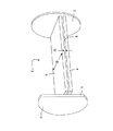
図1(a)は、3〜12ミクロンの長さのレーザ出力波長を生成するために使用され、特許文献1に示される従来技術と一致する、従来の長方形状非対称複合型平面導波路ガスレーザ装置1の斜視図である。共振器ミラー2,3間で形成されるレーザキャビティ内で利得を生成するために、電極間の寸法Aの狭い隙間5内で無線周波数放電を励起することにより、多くの場合スラブと呼ばれる2つの金属平面電極4の間に無線周波数ガス放電が生成される。この技術の概要については、特許文献2を参照されたい。レーザは、互いに異なる鉛直方向の寸法Aおよび水平方向の寸法B、並びにレーザ共振器ミラー2、3を有する。レーザ共振器ミラーは、凹型球面ミラーであり、より幅広の横の自由空間方向Bに負ブランチ不安定型共振器を形成し、ビームは、2つの共振器ミラーのうちの最も低い曲率半径を有するミラー3の硬質エッジ6を通過して出力結合される。幅の狭い交差方向Aでは、共振器ミラー2、3は平面電極4とともに、導波路を形成する。レーザの平面図が、図1(b)に与えられ、自由空間の不安定方向を示しており、断面図が、図1(c)に示され、共振器の導波路方向を示している。以下の議論は、従来の補正方式が、非対称複合型平面導波路レーザ共振器からの出力ビームを、大部分のレーザ加工用途のための必要条件である、円形の回折限界ビームに整形することへの制約を概説している。
FIG. 1 (a) is a conventional rectangular asymmetric composite planar waveguide gas laser device that is used to generate a laser output wavelength of 3-12 microns in length and is consistent with the prior art disclosed in US Pat. 1 is a perspective view of FIG. In order to generate gain in the laser cavity formed between the
図1(b)を参照し、内部共振器ビーム7は、共振器から、ミラー3の硬質エッジ6を通過して出力結合され、自由空間の不安定方向に、多くの場合トップハットと呼ばれる形状9を有するビーム8を生成する。この近視野ビームをその遠視野に適切に伝搬することが必要になり、その遠視野ビームの形状10は、隣接するサイドローブとともに中央最大値を有し、次にそれらのサイドローブは、ガウス型の回折限界ビーム形状を得るために空間フィルタを使用して除去される。遠視野への伝搬は、ビームが自然に伝搬することを許容することにより、または、凹面ミラーまたは収束レンズを使用して集束を生成することにより作り出される。一般に、自由空間の不安定方向での共振器の選択は、種類において共焦点であり、出力結合されたビーム8がその方向に視準されることを指している。3〜12ミクロンの範囲の選択された波長で動作するこの種類のレーザからの適切な出力結合を達成するために、視準されるビーム8が自然に遠視野に伝搬することを可能にするのに必要とされる距離は、数メートルの大きさのものであり、自由空間方向のビーム幅Cは、一般にそのような寸法のものである。これは、大概の設計について、自由空間方向の出力結合されたビーム8は、集束されなければならず、したがって、ビームの方向を変え、ガスレーザ放電容器の外部構造の長さに沿ってそのビームを折り戻すために、少なくとも2つの追加の外部ミラーを必要とすることを指す。この方法は、設計をできる限り小型に保ち、一方では、自由空間の遠視野を生成するために高集束出力光学機器を使用する必要性をさらに打ち消す。そこでは、フィルタをかけられたサイドローブ中に、強度の照射レベルが存在し、熱的な損傷を回避するように空間フィルタを備え付けるために、極めて高い程度の位置決め精度が必要とされるであろう。
Referring to FIG. 1 (b), the internal resonator beam 7 is coupled out of the resonator through the hard edge 6 of the
共振器の導波路方向が、図1(c)に表されている。上記のように、この方向は、共振器の自由空間の不安定方向に直交している。導波路ビーム11は、1〜2mmからの幅Aを有する導波路の隙間5で生成され、現存の近視野導波路ビーム形状12が、自由空間の不安定方向のより幅の広い視準されたビームと比べて極めて発散性であるが、自由空間の不安定ビームと異なり、近視野12と遠視野13の両方の断面形状が、ほぼガウス曲線であり、したがって空間フィルタリングを必要としないことを指す。一般に、既存の導波路ビーム11は、ある距離を伝搬することを許され、そこでは、そのビームの寸法は、自由空間ビームの寸法に等しい。次に、導波路ビームの波面曲率半径(発散)は、円筒状ミラー/レンズまたは角度のある球面ミラーを使用して、自由空間ビームの曲率半径に整合するように補正され、この補正は、自由空間ビームが空間的にフィルタに通される前か、または、通された後に生じる。ガスレーザ放電容器の外部構造の長さに沿ってビームを折り戻すために使用される前述の2つの折りたたみ式ミラーを使用することは、通常の手順であり、導波路方向の若干の、または全ての補正を行う。しかし、レーザ放電容器の長さよりも長くは補正方式を保たないという制限内で、必要な補正を成し遂げるために、多くの場合、追加的なビームの折り畳みを利用することが必要とされる。上記の設計は、多くの場合、追加のフレームワークと光学的備え付けシステムを必要とし、費用と全体の構造の重量が嵩む。これらの問題に加えて、補正システムの光出力に対する、共振器ビーム特性と耐性の変動を許容することが必要あり、補正システムが、その構成補正光学機器の位置決めと入射角の両方について、ある程度調節可能でなければならないことを指す。
したがって、本発明の目的は、従来の非対称複合型平面導波路装置の必要とされるビーム補正にともなう上記の障害と欠点を除くことである。より具体的には、本発明の目的は、さらなる外部補正を必要としない、円形の擬似回折限界ビームを生成する非対称複合型平面導波路共振器で動作するガスレーザ容器を提供することである。上記の装置は、従来の補正システムを有する非対称複合型平面導波路レーザと比べると、組み立てがより簡単であり、費用面でより安価で、重量でより軽くなる。 Accordingly, it is an object of the present invention to eliminate the above-mentioned obstacles and disadvantages associated with the beam correction required for conventional asymmetric composite planar waveguide devices. More specifically, it is an object of the present invention to provide a gas laser container operating with an asymmetric composite planar waveguide resonator that produces a circular pseudo-diffraction limited beam that does not require further external correction. The above apparatus is easier to assemble, cheaper in terms of cost and lighter in weight than an asymmetric composite planar waveguide laser with a conventional correction system.
本発明によると、添付の請求の範囲で説明されるような、装置および方法が提供される。本発明の他の特徴は、従属請求項と次の説明から明らかになる。
本発明の第1の態様によると、ガスレーザ放電容器は、非対称複合型平面導波路共振器、光学集束システム/集束光学機器および追加の導波路ストリップ長で動作する。追加の導波路ストリップと集束システム/集束光学機器は、好ましくは、複合型平面導波路共振器からの出力ビームに作用し、自由空間の不安定方向に、導波路ストリップの出口でビームウェストを形成して、その導波路ストリップは、その位置で形成される直交導波路ビームウェストの寸法に整合し、円形の出力を生成する。さらに、自由空間の不安定ビームは、今、その遠視野と呼ばれる場所にあり、追加の導波路ストリップの出口の近くの点で、またはそのすぐ後に、空間的にフィルタに通され、円形の擬似回折限界ビームを生成し、そのビームが放電容器から出た後、さらなる外部補正を必要としない。
According to the present invention there is provided an apparatus and method as set forth in the appended claims. Other features of the invention will be apparent from the dependent claims and the following description.
According to a first aspect of the invention, the gas laser discharge vessel operates with an asymmetric composite planar waveguide resonator, an optical focusing system / focusing optics and an additional waveguide strip length. The additional waveguide strip and focusing system / focusing optics preferably act on the output beam from the composite planar waveguide resonator to form a beam waist at the exit of the waveguide strip in the direction of free space instability The waveguide strip then matches the dimensions of the orthogonal waveguide beam waist formed at that location, producing a circular output. In addition, the free space unstable beam is now in a location called its far field and is spatially filtered at a point near or immediately after the exit of the additional waveguide strip to create a circular simulation. A diffraction limited beam is generated and no further external correction is required after the beam exits the discharge vessel.
本発明の第2の態様によると、ガスレーザ放電容器は、非対称複合型平面導波路共振器、光学集束システム/集束光学機器および追加の導波路長で動作する。追加の導波路ストリップと集束システム/集束光学機器は、好ましくは、非対称複合型平面導波路共振器からの出力ビームに作用し、自由空間の不安定方向に、ビームが追加の導波路ストリップから伝搬された後に短距離で、ビームウェストを形成する。 According to a second aspect of the invention, the gas laser discharge vessel operates with an asymmetric composite planar waveguide resonator, optical focusing system / focusing optics and additional waveguide length. The additional waveguide strip and focusing system / focusing optics preferably operate on the output beam from the asymmetric composite planar waveguide resonator so that the beam propagates from the additional waveguide strip in a free space unstable direction. After a short distance, form a beam waist.
自由空間のビームウェストの位置を、放電容器の内部または外部にあるように選択することができ、後の選択肢は、フィルタリングが、放電容器の組み立ておよび封止の後に付け加えられてもよいという利点を有している。ビームウェストの寸法と位置は、好ましくは、発散性導波路ビーム寸法が、その位置で、または自由空間ビームウェストが形成された後に短距離で整合するように設定されてもよい。次に、導波路ビーム発散度は、ビーム寸法が整合する場所に配置される円筒状ミラー/レンズを使用して、自由空間の不安定ビームの発散度と等しくなるように補正されることができ、円形ビームを生成する。自由空間のビームウェストの位置およびビームが円形である位置に応じて、補正円筒状ミラー/レンズが、放電容器の内部または外部に配置されてもよい。 The position of the free space beam waist can be selected to be inside or outside the discharge vessel, and the latter option has the advantage that filtering may be added after assembly and sealing of the discharge vessel. Have. The size and position of the beam waist may preferably be set so that the diverging waveguide beam dimensions are aligned at that position or short distance after the free space beam waist is formed. The waveguide beam divergence can then be corrected to be equal to the divergence of an unstable beam in free space using a cylindrical mirror / lens located where the beam dimensions are matched. Generate a circular beam. Depending on the position of the free space beam waist and the position where the beam is circular, a correction cylindrical mirror / lens may be placed inside or outside the discharge vessel.
本発明の第1および第2の態様について、非対称複合型平面導波路共振器の設計は、好ましくは、目的に合わせて準備され、共振器平面導波路放電と平行して隣接する追加の平面導波路ストリップの位置を定める。具体的には、レーザにより、非対称複合型平面導波路は、好ましくは、2面ミラー負ブランチ共振器として構成され、その共振器は、最大の曲率半径を有する共振器キャビティミラーを通過して、ビームを出力結合する。これは、次に好ましくは、集束システムが簡易で球状の凹面ミラーであることを可能にし、その集光システムは、出力結合されるビームに対してほぼ垂直の入射で機能し、共振器の平面導波路放電に平行して隣接する追加の平面導波路ストリップ内に、共振器出力ビームを入力結合する。さらに、上述のような非対称複合型平面導波路レーザ共振器は、共焦点共振器とみなされる点の近くの、または、まさにその点にある構成で動作し、それは、長方形状スラブ放電から利得を効果的に引き出すことを促進する。共振器出力ビームのための有効な幾何学上の原点は、共振器の理論的な共焦点の近くであるか、またはその点に正確に一致する。 For the first and second aspects of the present invention, the design of the asymmetric composite planar waveguide resonator is preferably an additional planar waveguide that is prepared for the purpose and is adjacent in parallel with the resonator planar waveguide discharge. Determine the location of the waveguide strip. Specifically, with the laser, the asymmetric composite planar waveguide is preferably configured as a two-sided mirror negative branch resonator, which passes through a resonator cavity mirror having the largest radius of curvature, Outcouple the beam. This in turn preferably allows the focusing system to be a simple spherical concave mirror, the focusing system functioning at near normal incidence with respect to the output coupled beam and the plane of the resonator. The resonator output beam is input coupled into an additional planar waveguide strip adjacent and parallel to the waveguide discharge. Furthermore, the asymmetric composite planar waveguide laser resonator as described above operates in a configuration near or exactly at the point considered as a confocal resonator, which gains gain from a rectangular slab discharge. Promote effective withdrawal. The effective geometric origin for the resonator output beam is near or exactly coincides with the theoretical confocal point of the resonator.
さらに、非対称複合型平面導波路共振器は、共振器のこの第2の態様において、好ましくは、凹面曲率半径を有する共振器キャビティミラーを通過して、ビームを出力結合する2面ミラー正ブランチ共振器として構成されている。これは、再び、集束システムが簡単な、球面凹ミラーであることを可能にし、出力結合されたビームにほぼ垂直な入射で動作し、共振器の平面導波路放電に平行して隣接する追加の平面導波路ストリップに、共振器出力ビームを入力結合する。再び、この共振器は、共焦点共振器とみなされる点の近くにあるか、または、まさにその点にある構成で動作することができ、それは、前の通り、長方形状スラブ放電から利得を効果的に引き出すことを促進する。共振器出力ビームのための有効な幾何学上の原点は、共振器の理論的な共焦点の近くであるか、またはその点に正確に一致する。 In addition, an asymmetric composite planar waveguide resonator is preferably a two-plane mirror positive branch resonance in this second aspect of the resonator that preferably couples the beam through a resonator cavity mirror having a concave radius of curvature. It is configured as a container. This again allows the focusing system to be a simple, spherical concave mirror, which operates at near normal incidence to the output coupled beam and is adjacent to and parallel to the planar waveguide discharge of the resonator. A resonator output beam is input coupled to the planar waveguide strip. Again, this resonator can be in the vicinity of a point that is considered a confocal resonator, or can operate in a configuration that is exactly at that point, which, as before, has gained effect from a rectangular slab discharge. To pull out. The effective geometric origin for the resonator output beam is near or exactly coincides with the theoretical confocal point of the resonator.
好ましくは、導波路ストリップ長は、横方向の大きさを有し、その大きさは、第1の態様の平面導波路共振器からの出力ビームを効率的に入力結合するのに適した寸法である。
第1の態様の導波路ストリップは、その長さが集束システム/光学機器の出力と関連しており、好ましくは、自由空間の不安定方向に、導波路ストリップの端部で形成されるビームウェストの中央の突出部が、直交導波路ビームウェストの突出部と等しいように選択されることになる。
Preferably, the waveguide strip length has a lateral dimension, which is a dimension suitable for efficient input coupling of the output beam from the planar waveguide resonator of the first aspect. is there.
The waveguide strip of the first aspect has a length associated with the output of the focusing system / optical instrument, preferably a beam waist formed at the end of the waveguide strip in the unstable direction of free space. Will be selected to be equal to the projection of the orthogonal waveguide beam waist.
好ましくは、導波路ストリップ長は、導波路ストリップ出口の近くに、またはその直後に配置される空間的フィルタを含み、その空間フィルタは、自由空間の不安定方向のビームの第2のサイドローブを除去するように作用し、それにより、円形擬似回折限界ビームを与える。 Preferably, the waveguide strip length includes a spatial filter disposed near or immediately after the waveguide strip exit, the spatial filter comprising a second sidelobe of the beam in a free space unstable direction. Acts to remove, thereby providing a circular pseudo-diffraction limited beam.
好ましくは、第2の態様の導波路ストリップ長は、自由空間方向のビームウェストが、ビームが追加の導波路ストリップから伝搬した後に短距離で形成されるような、選択される集束システム/光学機器の出力と関連する長さを有し、好ましくは、ガスレーザ容器の内部か、または外部に含まれる。 Preferably, the waveguide strip length of the second aspect is selected such that the free space beam waist is formed at a short distance after the beam has propagated from the additional waveguide strip. And is preferably contained within or outside the gas laser vessel.
ビームウェスト位置の近くの、または、その位置の自由空間の不安定ビームに属している第2のサイドローブの空間フィルタリングは、好ましくは、回折限界ビームを生成するように与えられる。 Spatial filtering of the second sidelobe near the beam waist position or belonging to the free space unstable beam at that position is preferably provided to produce a diffraction limited beam.
ビームウェストの寸法と位置は、好ましくは、発散性導波路ビームの寸法が、その位置で、または、自由空間のビームウェストが形成された後に短距離で整合するように、設定されてもよい。次に、導波路ビーム発散度は、ビーム寸法が整合する位置に配置される円筒状ミラー/レンズを使用して、自由空間の不安定ビームの発散度に等しくなるように補正されることができ、円形の回折限界ビームを生成する。 The size and position of the beam waist may preferably be set so that the dimensions of the divergent waveguide beam align at that position or short distance after the free space beam waist is formed. The waveguide beam divergence can then be corrected to be equal to the divergence of an unstable beam in free space using a cylindrical mirror / lens located at a position where the beam dimensions match. Generate a circular diffraction limited beam.
非対称複合型平面導波路共振器は、最大の曲率半径を有する共振器キャビティミラーを通過して、ビームを出力結合する2面ミラー負ブランチ共振器であってもよい。
非対称複合型平面導波路共振器は、凹面曲率半径を有する共振器キャビティミラーを通過して、ビームを出力結合する2面ミラー正ブランチ共振器であってもよい。
The asymmetric composite planar waveguide resonator may be a two-plane mirror negative branch resonator that passes through a resonator cavity mirror having the largest radius of curvature and outcouples the beam.
The asymmetric composite planar waveguide resonator may be a two-plane mirror positive branch resonator that passes through a cavity cavity mirror having a concave radius of curvature and couples the beam out.
非対称複合型平面導波路共振器は、共焦点共振器とみなされる点の近くに、または正確にその点にある構成で動作するのに適合されていてもよく、それは、長方形状スラブ放電から利得を効果的に引き出すことを促進する。出力ビームのための有効な幾何学上の原点は、好ましくは、共振器の理論的な共焦点の近くにあるか、または正確にその点に一致する。 An asymmetric composite planar waveguide resonator may be adapted to operate near or exactly at a point that is considered a confocal resonator, which is gained from a rectangular slab discharge. Promote effective extraction. The effective geometric origin for the output beam is preferably near or exactly coincident with the theoretical confocal point of the resonator.
集束システム/光学機器は、導波路ストリップ長手方向軸が、スラブ導波路放電の長手方向の軸と平行に配置されるように、角度調節可能なミラー面または表面を含んでもよい。 The focusing system / optical instrument may include an angle adjustable mirror surface or surface such that the waveguide strip longitudinal axis is positioned parallel to the longitudinal axis of the slab waveguide discharge.
非対称複合型平面導波路共振器は、非対称複合型平面導波路共振器に属する共振ミラーのうちの1つとして働く単一の光学部品を組み込んでもよく、同じく、上記の集束システム/光学機器の一部または全体として作用する。 An asymmetric composite planar waveguide resonator may incorporate a single optical component that acts as one of the resonant mirrors belonging to the asymmetric composite planar waveguide resonator, and is also one of the focusing systems / optical equipment described above. Act as part or whole.
本発明の一態様によると、次を含んでいるガスレーザが提供される:
共振器ビームを集束させ、反射させるのに動作可能な導波路を形成している2つの実質的に平行な電極板と、
ガス放電を起こすために動作可能な励起手段と、
電極板の間で互いに向き合っている第1および第2の集束/反射手段と、
共振器ビームをガスレーザの出口に向けるために動作可能な第3の集束/反射手段とを含む。
According to one aspect of the invention, a gas laser is provided that includes:
Two substantially parallel electrode plates forming a waveguide operable to focus and reflect the resonator beam;
An excitation means operable to cause a gas discharge;
First and second focusing / reflecting means facing each other between the electrode plates;
And third focusing / reflecting means operable to direct the resonator beam to the exit of the gas laser.
共振器ビームは、好ましくは、電極板と第1および第2の集束/反射手段により生成される。利得は、ガス放電から得られ、光がガス放電を通過し、共振器ビームを引き起こす。 The resonator beam is preferably generated by an electrode plate and first and second focusing / reflecting means. Gain is obtained from the gas discharge, where light passes through the gas discharge and causes a resonator beam.
第1、第2および第3もしくは第2または第3の集束/反射手段は、好ましくは、湾曲した反射器である。
ガスレーザは、好ましくは、追加の導波路素子または導波路ストリップを含み、それらは、好ましくは、電極板により形成される導波路に隣接し、好ましくは、その導波路と同一平面上にある。第3の集束/反射手段は、好ましくは、既存の共振器ビームを集束させるために動作可能であり、好ましくは自由空間の不安定方向に、実質的には追加の導波路素子の出口またはその近くで、ビームウェストを形成する。ビームウェストは、追加の導波路素子を越えて形成されてもよい。
The first, second and third or second or third focusing / reflecting means are preferably curved reflectors.
The gas laser preferably includes additional waveguide elements or waveguide strips, which are preferably adjacent to the waveguide formed by the electrode plates and are preferably coplanar with the waveguide. The third focusing / reflecting means is preferably operable to focus the existing resonator beam, preferably in the unstable direction of free space, substantially at the exit of the additional waveguide element or its Close to form a beam waist. The beam waist may be formed beyond the additional waveguide element.
追加の導波路は、好ましくは、出力共振器ビームを導波路方向に束縛するために動作可能である。追加の導波路は、好ましくは、第3の集束/反射手段とガスレーザの出口との間に配置される。 The additional waveguide is preferably operable to constrain the output resonator beam in the waveguide direction. The additional waveguide is preferably arranged between the third focusing / reflecting means and the exit of the gas laser.
第3の集束/反射手段は、好ましくは、出力共振器ビームを集束させるために動作可能であり、ビームウェストを実質的に導波路方向のビームウェストの寸法と同じ寸法に形成し、その寸法は、好ましくは、追加の導波路素子のプレートの分離距離である。第3の集束/反射手段が、角度調節可能であってもよい。第3の集束/反射手段は、第1または第2の集束/反射手段の一方の一部分であってもよい。 The third focusing / reflecting means is preferably operable to focus the output resonator beam, forming a beam waist substantially the same dimension as the beam waist dimension in the waveguide direction, the dimension being , Preferably the separation distance of the plates of the additional waveguide element. The third focusing / reflecting means may be angle adjustable. The third focusing / reflecting means may be part of one of the first or second focusing / reflecting means.
レーザは、好ましくは自由空間方向の、出力共振器ビームのサイドローブを除去するのに適合されている空間フィルタリング手段を含む。好ましくは、空間フィルタリング手段は、レーザの出口に、またはその近くに配置される。 The laser includes spatial filtering means adapted to remove side lobes of the output resonator beam, preferably in the free space direction. Preferably, the spatial filtering means is arranged at or near the exit of the laser.
レーザは、非対称平面導波路共振器レーザであってもよい。
レーザ放電のより幅の広い平面方向の第1および第2、もしくは第1または第2の集束/反射手段は、好ましくは、準共焦点または共焦点共振器を形成するために選択される。
The laser may be an asymmetric planar waveguide resonator laser.
The broader planar first and second, or first or second focusing / reflecting means of the laser discharge are preferably selected to form a quasi-confocal or confocal resonator.
本発明は、ガス放電レーザのための共振器に拡張され、前記共振器は、電極板と、先の態様の集束/反射手段を組み込んでいる。
本発明の別の態様によると、レーザ共振器ビームを生成する方法が提供され、前記方法は、
実質的に平行な電極板を用いて、ガスの無線周波数励起によりガス内に放電を起こす工程と、
第1および第2の集束/反射手段の間で放電を反射および集束させることにより生成される光から利得を引き出す工程と、
第3の集束/反射手段を用いて、前記共振器ビームを出口に案内する工程とを含む。
The invention extends to a resonator for a gas discharge laser, which incorporates an electrode plate and the focusing / reflecting means of the previous embodiment.
According to another aspect of the invention, a method for generating a laser resonator beam is provided, the method comprising:
Using a substantially parallel electrode plate to cause a discharge in the gas by radio frequency excitation of the gas;
Extracting gain from light generated by reflecting and focusing the discharge between the first and second focusing / reflecting means;
Using a third focusing / reflecting means to guide the resonator beam to the outlet.
本明細書に記載されるすべての特徴は、上記の任意の態様と、任意の組み合わせで組み合わされてもよい。
本発明のさらなる理解のために、本発明のどの実施形態が実行されてもよいかを示すために、例として、付属の図面を参照する。
All features described herein may be combined in any combination with any of the above aspects.
For a further understanding of the invention, reference will now be made, by way of example, to the accompanying drawings in order to show which embodiments of the invention may be implemented.
本発明の好ましい実施形態は、付属の図面、すなわち、図2(a)、図2(b)および図2(c)を参照して、記載されることになる。図2(a)は、好ましい実施形態の光学および放電構造の斜視図を示す。ガス放電構造142は、2つの金属平板、長方形状電極152を含み、無線周波数励起ガス放電が、電極間の狭い間隙162内で実行される。隙間162の幅Dは、通常1〜2mmからであり、隙間幅Dは、放電構造の全体にわたり100ミクロン以内に保たれている。この均一な隙間は、電極の平らな金属表面とともに、共振器の狭い横方向軸Eにおいて、レーザ共振器のための導波路を形成する役割をする。スラブの幅G、または代わりに放電の端部に位置する共振器ミラーの幅により画定される共振器の広い平面方向自由空間軸Fにおいて、レーザ共振器は、この自由空間方向で、非対称不安定型共振器として動作し、レーザビームは、ミラーのうちの一方の硬質エッジを通過して出力結合される。共振器自由空間ビーム172の実線の光線軌跡が、図2(a)に示されている。
Preferred embodiments of the present invention will be described with reference to the accompanying drawings, ie, FIGS. 2 (a), 2 (b) and 2 (c). FIG. 2 (a) shows a perspective view of a preferred embodiment optical and discharge structure. The
上記のように、放電構造のどちらの端部でも、共振器ミラーが配置されている。これらのミラーの両方は、ガス放電に向き合う表面上に加工された球状凹曲率半径を有し、平面方向自由空間軸Fにおいて準共焦点または共焦点負ブランチ、不安定光学システムを形成する。最小の曲率半径182を有している共振器ミラーは、ビームが放電構造とレーザ容器から出る放電端部に配置されている。放電の反対側の端部に、最大の曲率半径を有する共振器ミラー192があり、このミラー192は、硬質エッジ202を有し、共振器からのビームの出力結合を可能にしている。ミラー192に隣接して、放電に向き合う表面上に加工された球面凹形曲率半径を有している第3のミラー212がある。第3のミラー212の角度は、レーザ共振器Oの光軸に対して傾けられているレーザ共振器から出力を取り出すような角度であり、レーザ共振器Oの光軸に平行なガス放電の隣接する部分に沿って、出力ビーム222を折り戻す。放電232のこの部分は、このとき、追加の導波路ストリップとして働く。追加の導波路ストリップ232の出口の直後に、空間フィルタ242が、自由空間方向に出力結合されたビームを空間的にフィルタにかけるように、配置されている。一般に、空間フィルタは、反射性の装置であり、おそらく一般的に金属性であるが、必ずしもそうである必要はなく、導波路隙間寸法Dと類似した幅Hのスロット262が、その空間フィルタ内に加工される。それは、自由空間ビームの中央最大部が通過することを可能にし、一方ではさらに、主要なビームからの不必要な自由空間サイドローブを反射させる。導波路の出口から2、3センチメートル後退させて空間フィルタを配置することが望ましく、反射された自由空間サイドローブを共振器の光路から離れるように方向付けることができ、それにより光学「帰還」を止めて、さらに無線周波数励起放電からフィルタの金属構造への潜在的なフラッシュオーバーを回避している。
As described above, resonator mirrors are arranged at either end of the discharge structure. Both of these mirrors have a spherical concave radius of curvature machined on the surface facing the gas discharge and form a quasi-confocal or confocal negative branch, unstable optical system in the planar free space axis F. A resonator mirror having a minimum radius of
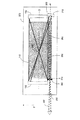
図2(b)は、図2(a)に表される好ましい実施形態の平面図であり、広い平面方向自由空間の不安定方向の共振器と補正を示し、さらに放電容器272の輪郭と、出力ビームが放電容器から伝搬することを可能にする容器壁内の容器光学窓282とを含んでいる。共振器内の自由空間不安定ビーム172は、実線の光線軌跡として再び表されている。本発明では、出力ビーム222は、第3のミラー212により放電容器の長さに沿って折り返される前に、放電容器272の背面でレーザ共振器から出る。共振器は、共振器から離れるビーム222が発散性であり、放電センターの近くの仮想点光源302から始まるように、設計されている。第3のミラー212の曲率半径と共振器からの出力結合との程度の適切な選択を通じて、結果として生じるビーム222は、追加の導波路ストリップ232の出口312でビームウェストを有し、フィルタにかけられるとき、擬似回折限界の自由空間ビームを生成する。その自由空間ビームの寸法は、図2(c)に示される追加の導波路ストリップ232の出口312での直交導波路ビームウェストの寸法に等しい。図2(c)は、図2(b)の軸線Pに沿って取られるレーザ放電容器の断面図である。このように、レーザ放電容器272から出ているビーム222は、円形で、フィルタにかけられており、さらなる補正を必要としない。図2(b)に戻り、追加の導波路ストリップの出口232で自由空間ビームをフィルタにかけることができるのは、自由空間ビームが遠視野にあるとみなされているからであり、従来の先行技術の平面導波路レーザ共振器と従来の補正を用いる場合、この状況は、放電容器の内部に生成することはできず、本発明に背景を述べている部分で議論されてきた。注意する別の重要な点は、レーザ共振器から出ているビームが円形であるように、従来の非対称平面導波路レーザを構成することができることである。すなわち、出力自由空間不安定性ビーム寸法と導波路ビーム寸法は、同じであり、上記の構成は、マイクロ波励起ガス放電を詳述している特許文献3で示された。平面導波路共振器の出口からの現存の発散性ビームの伝搬の後、導波路ビームウェストの寸法とレーザが動作する選択された波長に応じて、ビームは、理論的には、自由空間方向に、導波路の出口から0.3m未満の距離で空間的にフィルタにかけることができ、自由空間不安定ビームを集束させる必要はない。しかし、このアプローチは、200ワット以下の出力で動作するレーザに限定されており、その実用的な用途が、平面導波路放電の許容平面方向の幅により制約されるからである。この制約の理由は、共振器のわずかな出力結合が、平面導波路放電の幅により分けられる出力ミラーの硬質エッジを通過して、共振器から出ている自由空間ビームの幅により、おおよそ与えられることである。理想的には、約0.06〜0.2の微小な値が、一般に、3〜12ミクロンの波長で動作するこれら種類の平面導波路ガス放電レーザ共振器から、最も効率的な出力抽出を与える。残念なことに、微小な値が0.06以下に下がり始めると、出力抽出効率は、全く劇的に落ちる。この傾向は、20〜30mm以下の平面方向の幅を有し、通常1〜2mmの範囲である選択される導波路隙間寸法に依存する平面導波路ガス放電へのこの先行技術のアプローチの実用的な用途を限定する。特許文献3に表されるような、この種類の平面導波路レーザからの放射レベルが、極めて高く、3〜12ミクロン波長領域で機能する窓基板のために一般的に利用される材料を使用するとき、放電容器の光学窓の光学損傷に至ることがありえることに注意するべきである。これは、本発明の好ましい実施形態の事例でもあるようだが、本発明の場合、図2(a)、図2(b)および図2(c)に戻り、金属電極152が、長方形であるように示されており、それらの金属電極の全長にわたっている追加の導波路ストリップ232をともなっている。これは、すべてのデザインと出力レベルに対して、必ずしもこの事例である必要はない。平面導波路ガス放電レーザの出力が増えるにつれて、通常、面導波路電極増加の幅と長さは、より大きな範囲の利得を生成するために増加する。放電活性領域のこの領域のスケーリングは、平面導波路電極152の全長にわたらない追加の導波路ストリップ長になりやすい。このように、放電容器の光学窓282から十分な距離で、円形ビームを生成することができ、したがって、放電容器の光学窓282での発散性出力ビームの寸法は、放射レベルがもはや光損傷を起こさない値まで増加した。当然、この方式の実現は、空間フィルタ242の利用を必要とし、その空間フィルタは、追加の導波路ストリップ232の出口の近くに配置するために、無線周波数放電から電気的に絶縁されており、フィルタに通されたビームが光学的にレーザ共振器に「帰還」することができないように設計されている。
FIG. 2 (b) is a plan view of the preferred embodiment represented in FIG. 2 (a), showing the resonators and corrections for the unstable direction of the wide planar free space, and the contour of the
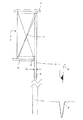
図3(a)は、本発明の好ましい実施形態の派生体のための平面図を示す。この異形では、第3のミラー213は、自由空間不安定方向に結果として生じる出力ビーム223が、好ましい実施形態の場合のような追加の導波路ストリップ233の出口323ではなく、ビームが追加の導波路ストリップから出た後の短距離の位置333でビームウェストを有するような曲率半径を有する。このアプローチは、設計がもはや追加の導波路ストリップの端部で等しいビーム寸法を有するように制約されないので、広い範囲のさまざまな共振器出力結合と追加の導波路ストリップ長が、考慮されることを可能にする。また、位置333が、放電容器の境界の内部または外部にあるように選択されることができることに注意するべきである。位置333を放電容器の境界の外部に設定することへの潜在的利点は、フィルタリングが、エンドユーザーに選択肢として提供されることができることである。これに対して、位置333を放電容器の境界の外部にすることへの不利な点は、本発明の二酸化炭素ガスレーザの異形についての平均的レーザ出力が200W以下の値に限定されることであり、それは、窓基板のために一般に入手可能な材料を使用する場合に、放電容器の出力窓283について形成される許容放射レベルが制約されることに起因する。自由空間方向に擬似回折限界ビームを生成するように自由空間方向で機能する空間フィルタ243が、位置333に直接、配置される。空間フィルタの切れ込み幅は、自由空間ビームの中心最大値の3*w0にほぼ等しく、ここで、w0は、従来の1/e2ビーム半径である。図3(b)に、図3(a)の線Pに沿って取られるレーザ放電容器の断面図が示されており、出力ビーム223が、追加の導波路ストリップ233から出るように、導波路方向に分かれていることを実証している。導波路発散が直交自由空間ビームウェストの発散に整合するように導波路発散を補正するために、円筒形レンズ343は、直交する方向でのビーム寸法が等しい所にある位置353に配置されている。円筒形レンズ343の焦点距離は、次に異なる発散が整合するように選択されており、円形回折限界ビームを生成する。自由空間方向に対して選択されるビームウェスト寸法と位置に応じて、位置353が、位置333またはより遠い距離のどちらかでありえることに注意するべきである。これは、位置333が放電容器の内部にある場合、この補正光学機器が、放電容器の内部にありえ、光学機器343と283が1つであり同じ光学機器であるように、装置を密封する役割を潜在的に果たしえることを指す。
FIG. 3 (a) shows a plan view for a derivative of the preferred embodiment of the present invention. In this variant, the
本発明の共振器をより良く説明するために、本発明の非対称負ブランチ共振器の共焦点の異形が、自由空間方向の平面図として図4に示されている。本発明の補正用の第3のミラーは、図示されていない。自由空間方向では、共焦点または準共焦点非対称共振器が動作し、その共振器は、各ミラー上に曲率半径を形成している2つのミラー184と194との間で形成されている。形成された表面は、互いに向き合い、レーザ放電144を横断し、正面共振器を形成する。ミラー面の曲率半径は、共振器が自由空間方向で不安定性として描写されることができるように、最初に選択される。この不安定要件は、共振器自由空間幾何学形状パラメータ積(g1*g2)が次の境界条件外にある場合に満たされる:
0≦g1・g2≦1
ここで、g1=1−L/R1、および、g2=1−L/R2であり、Lは、放電を横断するミラーの間隔であり、R1は、ミラー184に対する自由空間ミラー曲率半径であり、R2は、ミラー194に対する自由空間ミラー曲率半径である。自由空間共振器のための第2の要件は、ミラー184と194に属している自由空間曲率半径により形成される光軸が、ガス放電144の主軸Tに平行であることである。これは、ガス放電から利得を効果的に引き出すことを促進する。自由空間共振器の光軸は、ミラー184と194に対する曲率半径の2つの中心を通り抜ける軸Oとして画定されている。図4では、ミラー184に対する曲率半径の中心は、位置354にあり、ミラー194に対する曲率半径の中心は、位置364にある。自由空間共振器のための第3の要件は、自由空間共振器が、共焦点または準共焦点であることであり、この要件は、ガス放電から利得を効果的に引き出すことを促進する。この要件は、自由空間共振器ミラー184,194に属している焦点が互いに交差する場合に満たされる。図4では、共振器の共焦交点は、304であり、ミラー184と194の焦点は、それぞれ374と384であり、曲率半径の中心をそれらのミラー表面に連結させているそれぞれの線に沿っての中間である。
In order to better describe the resonator of the present invention, a confocal variant of the asymmetric negative branch resonator of the present invention is shown in FIG. 4 as a plan view in the direction of free space. The third mirror for correction according to the present invention is not shown. In the free space direction, a confocal or quasi-confocal asymmetric resonator operates, which is formed between two
0 ≦ g1 ・ g2 ≦ 1
Where g1 = 1−L / R1 and g2 = 1−L / R2, L is the mirror spacing across the discharge, and R1 is the free space mirror radius of curvature for
議論中のこの点まで、提唱される要件は、特許文献3と特許文献1の先行技術で示されているように、さらに従来の共焦点非対称負ブランチ共振器により共有されている。しかし、従来の設計から離脱して、本発明のレーザ共振器ビームは、自由空間不安定方向に最大の曲率半径で共振器ミラー194上に加工された硬質エッジ204を通過して出射し、従来の設計とは、正に反対である。これにより、自由空間不安定方向での励起ビーム294は、従来の非対称ブランチ共振器の場合のように視準されるよりはむしろ発散性になり、発散性ビームの幾何学的原点は、共振器の共焦交点304になる。共振器ミラー184と194により囲まれる自由空間方向での放電の理想的な幅Qは、以下の表記より、自由空間共振器の拡大率Mと放電幅Wに関連する:
Q=W/M
ここで、自由空間共振器の拡大率Mは、比R2/R1として定められる。最終的に、放電から利得を効果的に引き出すことを促進するために、自由空間共振器のための第5の要件は、自由空間共振器の光軸Oが放電主軸Tに対して変移することである。軸のこの変移は共振器ミラー194上に加工されている硬質エッジ204から離れた方向にある。自由空間不安定型共振器の光軸OのオフセットSは、以下の表記により与えられる共振器ミラー194の硬質エッジ204に対して定められる:
S=W/(M2+M)
図5は、本発明の正ブランチ共振器の等価な平面図を示しており、本発明の補正用第3のミラーは、図示されていない。再び、負ブランチ等価物についての場合であったように、5つの要件がある。自由空間方向では、2つのミラー185と195との間で形成される共焦点または準共焦点非対称共振器が動作し、曲率半径は、各々のミラー上で形成され、形成された表面は、レーザ放電145を横断して互いに向き合い、共振器を形成する。ミラー面の曲率半径は、共振器が自由空間方向において不安定性として描写されるように、最初に選択される。
この不安定要件は、共振器自由幾何学形状パラメータ積(g1*g2)が、次の境界条件外にある場合に満たされる:
0≦g1・g2≦1
ここで、g1=1−L/R1、および、g2=1−L/R2であり、Lは、放電を横断するミラーの間隔であり、R1は、ミラー185に対する自由空間ミラー曲率半径であり、R2は、ミラー195に対する自由空間ミラー曲率半径である。この場合、185のミラー面は、凸面であり、負の値を有するR1になる。自由空間共振器のための第2の要件は、ミラー185と195に属している自由空間曲率半径により形成される光軸が、ガス放電145の主軸Tに平行であることである。これは、ガス放電から利得を効果的に引き出すことを促進する。自由空間不安定型共振器の光軸は、ミラー185と195に対する曲率半径の2つの中心を通り抜ける軸Oとして定められる。図5では、ミラー185,195に対する曲率半径の中心は、図の左の位置にある。自由空間共振器のための第3の要件は、自由空間共振器が、焦点性または準共焦点であることであり、この要件は、さらに、ガス放電から利得を効果的に引き出すことを促進する。この要件は、自由空間不安定型共振器ミラー185と195に属している焦点が、互いに交差する場合に満たされる。図5において、共振器の共焦交点は305であり、ミラー185と195の焦点は、それぞれ375と385であり、曲率半径の中心をミラー面と連結しているそれぞれの線に沿って中間にある。
Up to this point in discussion, the proposed requirements are further shared by conventional confocal asymmetric negative branch resonators, as shown in the prior art of US Pat. However, deviating from the conventional design, the laser resonator beam of the present invention exits through the
Q = W / M
Here, the enlargement factor M of the free space resonator is determined as a ratio R2 / R1. Finally, in order to promote effective extraction of gain from the discharge, the fifth requirement for the free space resonator is that the optical axis O of the free space resonator is shifted relative to the discharge main axis T. It is. This shift in axis is in a direction away from the
S = W / (M 2 + M)
FIG. 5 shows an equivalent plan view of the positive branch resonator of the present invention, and the third correcting mirror of the present invention is not shown. Again, as was the case for the negative branch equivalent, there are five requirements. In the free space direction, the confocal or quasi-confocal asymmetric resonator formed between the two
This instability requirement is met when the resonator free geometry parameter product (g1 * g2) is outside the following boundary conditions:
0 ≦ g1 ・ g2 ≦ 1
Where g1 = 1−L / R1 and g2 = 1−L / R2, L is the mirror spacing across the discharge, R1 is the free space mirror radius of curvature relative to mirror 185, R2 is the free space mirror radius of curvature for
議論のこの点まで、提唱される要件は、特許文献2の先行技術で示されるような、従来の共焦点非対称正ブランチ共振器により、同じく共有されている。
しかし、従来の設計から離脱して、本発明のレーザ共振器ビームは、自由空間不安定方向において凹面曲率半径で共振器ミラー195上に加工されている硬質エッジ205を通過して出射しており、凸面曲率半径で共振器ミラー上に加工された硬質エッジを有する従来の設計とは、全く反対である。これにより、自由空間不安定方向での共振器からの出力ビーム295は、従来の非対称正ブランチ共振器の場合のように視準されているよりはむしろわずかに発散性になり、発散しているビームの幾何学的原点は、共振器の共焦交点305になる。共振器ミラー185と195により囲まれる自由空間方向での放電の理想的な幅Qは、以下の表記により、自由空間共振器の拡大率Mと放電幅Wに関連する:
Q=W/M
式中、自由空間共振器の拡大率Mは、比R2/R1として定められる。最終的に、放電から利益を効果的に引き出すことを促進するために、自由空間共振器のための第5の要件は、自由空間共振器の光軸0が放電主軸Tに対して変位することである。軸のこの変位は、共振器ミラー195上で加工されている硬質エッジ205から離れた方向にある。自由空間不安定型共振器の光軸OのオフセットSは、光軸Oが、共振器ミラー195の硬質エッジ205から最も遠くにある放電長手方向エッジと同軸に通るようなものである。
Up to this point of discussion, the proposed requirements are also shared by conventional confocal asymmetric positive branch resonators as shown in the prior art of US Pat.
However, leaving the conventional design, the laser resonator beam of the present invention exits through the
Q = W / M
In the equation, the magnification factor M of the free space resonator is defined as the ratio R2 / R1. Finally, in order to facilitate effectively extracting the benefits from the discharge, the fifth requirement for the free space resonator is that the optical axis 0 of the free space resonator is displaced relative to the discharge main axis T. It is. This displacement of the axis is in a direction away from the
この出願と関連している本明細書と並行して、または、その前に出願されているすべての書類と文書、そして、本明細書とともに一般審査のために公開されているすべての書類と文書に注意が向けられる。すべての上記の書類と文書は、参考として本明細書に組み込まれている。 All documents and documents filed in parallel with or prior to this specification related to this application, and all documents and documents published for general examination with this specification Attention is directed to. All the above documents and documents are incorporated herein by reference.
本明細書(いずれの付属の請求項、要約および図面も含んでいる)で開示されるすべての特徴、およびそのように開示されるいずれの方法またはプロセスのすべての工程、もしくは本明細書(いずれの付属の請求項、要約および図面も含んでいる)で開示されるすべての特徴、またはそのように開示されるいずれの方法またはプロセスのすべての工程は、いずれの組み合わせで、組み合わされてもよいが、少なくともいくつかの上記の特徴および工程、もしくはいくつかの上記の特徴または工程が互いに相容れない組み合わせは除く。 All features disclosed in this specification (including any appended claims, abstracts and drawings), and all steps of any method or process so disclosed, or the specification (which (Including the appended claims, abstract and drawings), or all steps of any method or process so disclosed may be combined in any combination Except for at least some of the above features and steps, or combinations where some of the above features or steps are incompatible with each other.
本明細書(いずれの付属の請求項、要約および図面も含んでいる)で開示される各特徴は、明白に特に述べられない限り、同等な、等価な、または類似した目的に用いられる代わりの特徴に入れ替えられてもよい。このように、明白に特に述べられない限り、開示される各特徴は、一般的な一連の等価なまたは類似した特徴の一例である。 Each feature disclosed in this specification (including any appended claims, abstract and drawings) is intended to be used as an equivalent, equivalent or similar object, unless expressly stated otherwise. It may be replaced with a feature. Thus, unless expressly stated otherwise, each feature disclosed is one example of a generic series of equivalent or similar features.
本発明は、前述の実施形態の詳細に限定されない。本発明は、本明細書(いずれの付属の請求項、要約および図面も含んでいる)で開示される特徴のうちのいずれの新たなもの、もしくは、いずれの新たな組み合わせにも、または、そのように開示されるいずれの方法またはプロセスの工程のうちのいずれの新たなもの、もしくは、いずれの新たな組み合わせにも拡張される。 The invention is not limited to the details of the embodiments described above. The present invention is directed to any new or any new combination of features disclosed herein (including any appended claims, abstracts and drawings), or As such, it extends to any new or any new combination of steps of any method or process disclosed.
Claims (13)
ガス放電を起こすように動作可能な励起手段と、
共振器を形成するために、前記電極板(152)間で互いに対向する第1および第2の反射手段(182、192)であって、前記第1および第2の反射手段の各曲率半径および間隔は、前記電極板(152)に平行な自由空間面内の前記共振器が不安定共振器かつ実質的に共焦点共振器となるように設定されている第1および第2の反射手段と、
前記共振器ビームを前記ガスレーザの出口(282)に向けるように動作可能な前記共振器の外部にある第3の反射手段(212)とを備えるガスレーザ装置において、
前記共振器の外部にあり、前記第3の反射手段(212)と前記ガスレーザの前記出口(282)との間に配置される追加の導波路素子(232)を備え、前記第3の反射手段は前記共振器の一方の端部に隣接し、前記ガスレーザの前記出口(282)は前記共振器の反対側の端部に隣接していることを特徴とするガスレーザ装置。 Two substantially parallel electrode plates (152) forming a waveguide operable to focus and reflect the laser resonator beam;
An excitation means operable to cause a gas discharge;
In order to form a resonator, first and second reflecting means (182, 192) facing each other between the electrode plates (152), each having a radius of curvature of the first and second reflecting means and The distance between the first and second reflecting means set so that the resonator in a free space plane parallel to the electrode plate (152) is an unstable resonator and a substantially confocal resonator. ,
A gas laser device comprising third reflecting means (212) external to the resonator operable to direct the resonator beam to an exit (282) of the gas laser;
An additional waveguide element (232) located outside the resonator and disposed between the third reflecting means (212) and the outlet (282) of the gas laser, the third reflecting means Is adjacent to one end of the resonator, and the outlet (282) of the gas laser is adjacent to the opposite end of the resonator.
ガスの無線周波数励起により実質的に平行な電極板の間でガス放電を起こす工程と、
第1の反射手段(182)と第2の反射手段(192)との間で結果として生じる共振器ビームを反射させることにより、ガス放電から利得を引き出す工程と、
前記共振器の外部にある第3の反射手段(212)を使用して、前記共振器ビームを出口に案内する工程とを備える方法において、
前記ビームは、前記第3の反射手段(282)と前記ガスレーザの前記出口(282)との間に配置される追加の導波路素子(232)に沿って案内され、前記導波路素子(232)は前記共振器の外部にあり、前記第3の反射手段(212)は前記共振器の一方の端部に隣接し、前記ガスレーザの前記出口(282)は前記共振器の反対側の端部に隣接していることを特徴とする方法。 A method of manufacturing a laser device in a gas container,
Causing a gas discharge between substantially parallel electrode plates by radio frequency excitation of the gas;
Extracting the gain from the gas discharge by reflecting the resulting resonator beam between the first reflecting means (182) and the second reflecting means (192);
Using third reflecting means (212) external to the resonator to guide the resonator beam to an outlet.
The beam is guided along an additional waveguide element (232) arranged between the third reflecting means (282) and the outlet (282) of the gas laser, and the waveguide element (232) Is external to the resonator, the third reflecting means (212) is adjacent to one end of the resonator, and the outlet (282) of the gas laser is at the opposite end of the resonator. A method characterized by being adjacent.
Applications Claiming Priority (2)
| Application Number | Priority Date | Filing Date | Title |
|---|---|---|---|
| EP07119271.0 | 2007-10-25 | ||
| EP07119271A EP2053708A1 (en) | 2007-10-25 | 2007-10-25 | Gas laser device |
Publications (2)
| Publication Number | Publication Date |
|---|---|
| JP2009105408A true JP2009105408A (en) | 2009-05-14 |
| JP5517434B2 JP5517434B2 (en) | 2014-06-11 |
Family
ID=39156116
Family Applications (1)
| Application Number | Title | Priority Date | Filing Date |
|---|---|---|---|
| JP2008272108A Active JP5517434B2 (en) | 2007-10-25 | 2008-10-22 | Gas laser apparatus and laser generation method |
Country Status (5)
| Country | Link |
|---|---|
| US (1) | US8116348B2 (en) |
| EP (2) | EP2053708A1 (en) |
| JP (1) | JP5517434B2 (en) |
| CN (1) | CN101420101B (en) |
| ES (1) | ES2629987T3 (en) |
Families Citing this family (11)
| Publication number | Priority date | Publication date | Assignee | Title |
|---|---|---|---|---|
| CN108123354A (en) * | 2010-08-10 | 2018-06-05 | 丹特雷有限公司 | Laser aid and system and its medical laser treatment system |
| CN103326223A (en) * | 2013-05-22 | 2013-09-25 | 四川大学 | Super-large wide and thin light beam gas laser |
| US9231362B2 (en) * | 2014-06-06 | 2016-01-05 | Synrad, Inc. | Multi-pass slab laser with internal beam shaping |
| WO2017075732A1 (en) * | 2015-11-03 | 2017-05-11 | 徐海军 | Radio frequency excited laser provided with cylindrical collimating lens |
| CN105375252A (en) * | 2015-11-03 | 2016-03-02 | 北京热刺激光技术有限责任公司 | Radio frequency laser with cylindrical surface collimating mirror |
| DE102016116779A1 (en) * | 2016-09-07 | 2018-03-08 | Rofin-Sinar Laser Gmbh | Resonator mirror for an optical resonator of a laser device and laser device |
| US10985518B2 (en) | 2016-09-20 | 2021-04-20 | Iradion Laser, Inc. | Lasers with setback aperture |
| FR3057363B1 (en) * | 2016-10-11 | 2019-05-24 | Commissariat A L'energie Atomique Et Aux Energies Alternatives | OPTICAL CAVITY PENDULUM WITH STRONG FOLDING. |
| WO2019094722A1 (en) * | 2017-11-10 | 2019-05-16 | Boston Scientific Scimed, Inc. | Apparatus and methodology for reshaping a laser beam |
| EP3793044B1 (en) * | 2019-09-12 | 2021-11-03 | Kern Technologies, LLC | Output coupling from unstable laser resonators |
| CN113115136B (en) * | 2021-03-17 | 2024-01-30 | 桂林电子科技大学 | Optical router bridging fault positioning method based on single fault model |
Citations (15)
| Publication number | Priority date | Publication date | Assignee | Title |
|---|---|---|---|---|
| JPH01257382A (en) * | 1987-08-31 | 1989-10-13 | Deutsche Forsch & Vers Luft Raumfahrt Ev | High output waveguide laser |
| JPH0371683A (en) * | 1989-08-11 | 1991-03-27 | Mitsubishi Electric Corp | Gas laser device |
| JPH03155684A (en) * | 1989-08-11 | 1991-07-03 | Mitsubishi Electric Corp | Gas laser device |
| JPH04199583A (en) * | 1990-11-29 | 1992-07-20 | Toshiba Corp | Gas laser oscillator |
| JPH04261080A (en) * | 1991-01-25 | 1992-09-17 | Mitsubishi Electric Corp | Gas laser device |
| JPH04332182A (en) * | 1991-05-07 | 1992-11-19 | Toshiba Corp | Laser apparatus |
| JPH05505701A (en) * | 1990-03-21 | 1993-08-19 | ロフイン―ジナール レーザー ゲゼルシヤフト ミツト ベシユレンクテル ハフツング | gas laser |
| JPH0690048A (en) * | 1990-10-12 | 1994-03-29 | Coherent Inc | Pulse-wave co2 laser |
| JPH06152037A (en) * | 1992-11-05 | 1994-05-31 | Mitsubishi Electric Corp | Gas laser apparatus |
| JPH08512433A (en) * | 1993-07-12 | 1996-12-24 | コヒーレント・インク | Gas slab laser with folded cavity structure |
| JP2000506319A (en) * | 1996-03-13 | 2000-05-23 | ロフイン―ジナール レーザー ゲゼルシヤフト ミツト ベシユレンクテル ハフツング | Strip laser |
| JP2001053362A (en) * | 1999-08-11 | 2001-02-23 | Matsushita Electric Ind Co Ltd | Gas laser |
| JP2001168428A (en) * | 1999-12-07 | 2001-06-22 | Matsushita Electric Ind Co Ltd | Gas laser |
| JP2002540607A (en) * | 1999-03-19 | 2002-11-26 | ゴスダーストベンノイ プレドプリアテイ ノーチェノ−イスルドバテルスキー インステイチュート ラゼルノイ フィチキ | Laser device |
| JP2006525649A (en) * | 2003-05-07 | 2006-11-09 | フェデラルノイェ・ゴスダルストヴェンノイェ・ウニタルノイェ・プレドプリヤティエ・“ナウチノ−プロイズヴォドストヴェンナヤ・コルポラツィヤ・ゴスダルストヴェンニー・オプティチェスキー・インスティトゥト・ | Laser with hybrid unstable ring resonator |
Family Cites Families (12)
| Publication number | Priority date | Publication date | Assignee | Title |
|---|---|---|---|---|
| US533524A (en) | 1895-02-05 | Attachment for animal-traps | ||
| US4719639B1 (en) * | 1987-01-08 | 1994-06-28 | Boreal Laser Inc | Carbon dioxide slab laser |
| US5048048A (en) * | 1989-08-11 | 1991-09-10 | Mitsubishi Denki K.K. | Gas laser device |
| US5335242A (en) * | 1990-10-12 | 1994-08-02 | Coherent, Inc. | Resonator for CO2 slab waveguide laser |
| JP2613831B2 (en) * | 1991-12-27 | 1997-05-28 | 三菱電機株式会社 | Laser device |
| JP3316698B2 (en) * | 1992-10-21 | 2002-08-19 | 三菱電機株式会社 | Laser device |
| DE19645093C2 (en) * | 1996-11-01 | 2000-01-27 | Deutsch Zentr Luft & Raumfahrt | Waveguide laser system |
| DE19734641A1 (en) * | 1997-08-11 | 1999-02-18 | Rofin Sinar Laser Gmbh | Stripline laser with an optical imaging system for beam shaping |
| EP1116307A1 (en) * | 1998-09-21 | 2001-07-18 | Peter Vitruk | Stable multi-fold telescopic laser resonator |
| US6463086B1 (en) * | 1999-02-10 | 2002-10-08 | Lambda Physik Ag | Molecular fluorine laser with spectral linewidth of less than 1 pm |
| JP2002016304A (en) * | 2000-06-28 | 2002-01-18 | Mitsubishi Heavy Ind Ltd | Unstable type resonator |
| WO2004049524A1 (en) * | 2002-11-28 | 2004-06-10 | Gosudarstvennoye Predpriyatie Nauchnoissledovatelsky Institut Lazernoy Fiziki | High power slab type gas laser |
-
2007
- 2007-10-25 EP EP07119271A patent/EP2053708A1/en not_active Withdrawn
-
2008
- 2008-10-21 US US12/255,236 patent/US8116348B2/en active Active
- 2008-10-22 JP JP2008272108A patent/JP5517434B2/en active Active
- 2008-10-23 EP EP08167352.7A patent/EP2053707B1/en active Active
- 2008-10-23 ES ES08167352.7T patent/ES2629987T3/en active Active
- 2008-10-24 CN CN200810171210.1A patent/CN101420101B/en active Active
Patent Citations (15)
| Publication number | Priority date | Publication date | Assignee | Title |
|---|---|---|---|---|
| JPH01257382A (en) * | 1987-08-31 | 1989-10-13 | Deutsche Forsch & Vers Luft Raumfahrt Ev | High output waveguide laser |
| JPH0371683A (en) * | 1989-08-11 | 1991-03-27 | Mitsubishi Electric Corp | Gas laser device |
| JPH03155684A (en) * | 1989-08-11 | 1991-07-03 | Mitsubishi Electric Corp | Gas laser device |
| JPH05505701A (en) * | 1990-03-21 | 1993-08-19 | ロフイン―ジナール レーザー ゲゼルシヤフト ミツト ベシユレンクテル ハフツング | gas laser |
| JPH0690048A (en) * | 1990-10-12 | 1994-03-29 | Coherent Inc | Pulse-wave co2 laser |
| JPH04199583A (en) * | 1990-11-29 | 1992-07-20 | Toshiba Corp | Gas laser oscillator |
| JPH04261080A (en) * | 1991-01-25 | 1992-09-17 | Mitsubishi Electric Corp | Gas laser device |
| JPH04332182A (en) * | 1991-05-07 | 1992-11-19 | Toshiba Corp | Laser apparatus |
| JPH06152037A (en) * | 1992-11-05 | 1994-05-31 | Mitsubishi Electric Corp | Gas laser apparatus |
| JPH08512433A (en) * | 1993-07-12 | 1996-12-24 | コヒーレント・インク | Gas slab laser with folded cavity structure |
| JP2000506319A (en) * | 1996-03-13 | 2000-05-23 | ロフイン―ジナール レーザー ゲゼルシヤフト ミツト ベシユレンクテル ハフツング | Strip laser |
| JP2002540607A (en) * | 1999-03-19 | 2002-11-26 | ゴスダーストベンノイ プレドプリアテイ ノーチェノ−イスルドバテルスキー インステイチュート ラゼルノイ フィチキ | Laser device |
| JP2001053362A (en) * | 1999-08-11 | 2001-02-23 | Matsushita Electric Ind Co Ltd | Gas laser |
| JP2001168428A (en) * | 1999-12-07 | 2001-06-22 | Matsushita Electric Ind Co Ltd | Gas laser |
| JP2006525649A (en) * | 2003-05-07 | 2006-11-09 | フェデラルノイェ・ゴスダルストヴェンノイェ・ウニタルノイェ・プレドプリヤティエ・“ナウチノ−プロイズヴォドストヴェンナヤ・コルポラツィヤ・ゴスダルストヴェンニー・オプティチェスキー・インスティトゥト・ | Laser with hybrid unstable ring resonator |
Also Published As
| Publication number | Publication date |
|---|---|
| EP2053708A1 (en) | 2009-04-29 |
| US20090110016A1 (en) | 2009-04-30 |
| EP2053707A2 (en) | 2009-04-29 |
| CN101420101A (en) | 2009-04-29 |
| JP5517434B2 (en) | 2014-06-11 |
| EP2053707B1 (en) | 2016-12-28 |
| US8116348B2 (en) | 2012-02-14 |
| ES2629987T3 (en) | 2017-08-17 |
| CN101420101B (en) | 2013-11-06 |
| EP2053707A3 (en) | 2011-01-12 |
Similar Documents
| Publication | Publication Date | Title |
|---|---|---|
| JP5517434B2 (en) | Gas laser apparatus and laser generation method | |
| JP3265173B2 (en) | Solid state laser device | |
| TWI553978B (en) | Regenerative ring resonator | |
| JP5657139B2 (en) | CO2 laser device and CO2 laser processing device | |
| EP2628218B1 (en) | Ceramic gas laser having an integrated beam shaping waveguide | |
| US20050141583A1 (en) | Method and device for coherence reduction | |
| JP2005294393A (en) | Laser oscillator | |
| US6856639B2 (en) | High power slab type gas laser | |
| EP2362502B1 (en) | Mode selection technique for a waveguide laser | |
| CN105870770B (en) | Flat folded ceramic slab laser | |
| US8873599B2 (en) | Gas laser device | |
| US5848091A (en) | Laser resonator with improved output beam characteristics | |
| JP3621623B2 (en) | Laser resonator | |
| US8009715B2 (en) | Mode selection technique for a laser | |
| US5764680A (en) | Folded internal beam path for gas stable/unstable resonator laser | |
| US20190312403A1 (en) | Folded Slab Laser | |
| EP3793044B1 (en) | Output coupling from unstable laser resonators | |
| JP2002016304A (en) | Unstable type resonator | |
| CN109906534B (en) | Laser with indented aperture | |
| JP2005045174A (en) | Laser resonator and method for assembling the same | |
| JP2964202B2 (en) | Excimer laser oscillator | |
| Vitruk et al. | 700-W diffusion-cooled large-area 40.68-MHz excited CO2 laser employing split-wave hybrid confocal resonator | |
| Shemwell | High Power Free-Electron Laser Optical Cavities | |
| RU2003114580A (en) | LASER WITH HYBRID UNSTABLE RING RESONATOR |
Legal Events
| Date | Code | Title | Description |
|---|---|---|---|
| A621 | Written request for application examination |
Free format text: JAPANESE INTERMEDIATE CODE: A621 Effective date: 20111020 |
|
| RD04 | Notification of resignation of power of attorney |
Free format text: JAPANESE INTERMEDIATE CODE: A7424 Effective date: 20120106 |
|
| A977 | Report on retrieval |
Free format text: JAPANESE INTERMEDIATE CODE: A971007 Effective date: 20130226 |
|
| A131 | Notification of reasons for refusal |
Free format text: JAPANESE INTERMEDIATE CODE: A131 Effective date: 20130305 |
|
| A521 | Request for written amendment filed |
Free format text: JAPANESE INTERMEDIATE CODE: A523 Effective date: 20130605 |
|
| A131 | Notification of reasons for refusal |
Free format text: JAPANESE INTERMEDIATE CODE: A131 Effective date: 20130827 |
|
| A521 | Request for written amendment filed |
Free format text: JAPANESE INTERMEDIATE CODE: A523 Effective date: 20131127 |
|
| TRDD | Decision of grant or rejection written | ||
| A01 | Written decision to grant a patent or to grant a registration (utility model) |
Free format text: JAPANESE INTERMEDIATE CODE: A01 Effective date: 20140325 |
|
| A61 | First payment of annual fees (during grant procedure) |
Free format text: JAPANESE INTERMEDIATE CODE: A61 Effective date: 20140401 |
|
| R150 | Certificate of patent or registration of utility model |
Ref document number: 5517434 Country of ref document: JP Free format text: JAPANESE INTERMEDIATE CODE: R150 |
|
| R250 | Receipt of annual fees |
Free format text: JAPANESE INTERMEDIATE CODE: R250 |
|
| S531 | Written request for registration of change of domicile |
Free format text: JAPANESE INTERMEDIATE CODE: R313531 |
|
| S533 | Written request for registration of change of name |
Free format text: JAPANESE INTERMEDIATE CODE: R313533 |
|
| R350 | Written notification of registration of transfer |
Free format text: JAPANESE INTERMEDIATE CODE: R350 |
|
| R250 | Receipt of annual fees |
Free format text: JAPANESE INTERMEDIATE CODE: R250 |
|
| R250 | Receipt of annual fees |
Free format text: JAPANESE INTERMEDIATE CODE: R250 |
|
| R250 | Receipt of annual fees |
Free format text: JAPANESE INTERMEDIATE CODE: R250 |