JP2009103263A - Cable transmission mechanism - Google Patents

Cable transmission mechanism Download PDF

Info

Publication number
JP2009103263A
JP2009103263A JP2007277245A JP2007277245A JP2009103263A JP 2009103263 A JP2009103263 A JP 2009103263A JP 2007277245 A JP2007277245 A JP 2007277245A JP 2007277245 A JP2007277245 A JP 2007277245A JP 2009103263 A JP2009103263 A JP 2009103263A
Authority
JP
Japan
Prior art keywords
inner wire
housing
rotation
longitudinal direction
transmission mechanism
Prior art date
Legal status (The legal status is an assumption and is not a legal conclusion. Google has not performed a legal analysis and makes no representation as to the accuracy of the status listed.)
Pending
Application number
JP2007277245A
Other languages
Japanese (ja)
Inventor
Kaoru Tsubouchi
坪内  薫
Current Assignee (The listed assignees may be inaccurate. Google has not performed a legal analysis and makes no representation or warranty as to the accuracy of the list.)
Advics Co Ltd
Original Assignee
Advics Co Ltd
Priority date (The priority date is an assumption and is not a legal conclusion. Google has not performed a legal analysis and makes no representation as to the accuracy of the date listed.)
Filing date
Publication date
Application filed by Advics Co Ltd filed Critical Advics Co Ltd
Priority to JP2007277245A priority Critical patent/JP2009103263A/en
Publication of JP2009103263A publication Critical patent/JP2009103263A/en
Pending legal-status Critical Current

Links

Images

Landscapes

  • Flexible Shafts (AREA)
  • Braking Arrangements (AREA)

Abstract

<P>PROBLEM TO BE SOLVED: To extremely enhance reliability in a joining state of an inner wire of a cable and a driving member, the cable being capable of transmitting tensile force to an operation member from the driving member. <P>SOLUTION: An I-shaped connection part (y) orthogonal to the longitudinal direction of the inner wire is arranged in one end part 15a1 of the inner wire. A connection mechanism D1 having a connection member 62 and a rotation suppressing member 63 is interposed between the one end part 15a1 of the inner wire and the driving member. The connection member 62 has an insertion hole part capable of inserting the I-shaped connection part (y), a rotation allowable part 62b allowing rotation around an insertion hole of the I-shaped connection part (y) inserted into this insertion hole part, and an engaging part 62c engageable with the I-shaped connection part (y) in a state of rotating the I-shaped connection part (y) by a predetermined quantity by the rotation allowable part 62b. The rotation suppressing member 63 has a restraining part 63b attachable-detachable to a connection part of the connection member 52 and the one end part 15a1 of the inner wire and holding a state of rotating by the predetermined quantity of the I-shaped connection part (y). <P>COPYRIGHT: (C)2009,JPO&INPIT

Description

本発明は、例えば、電動パーキングブレーキ装置に適用可能なケーブル伝達機構に係り、特に、駆動部材と作動部材間に介装されて前記駆動部材から前記作動部材に引張り力を伝達可能なケーブルが、前記駆動部材に連結機構を介して一端部にて連結されるとともに他端部にて前記作動部材に連結されるインナーワイヤと、このインナーワイヤの両端部以外の外周を被覆し両端部を保持部材により移動不能に保持されるアウターチューブを備えているケーブル伝達機構に関する。   The present invention relates to a cable transmission mechanism applicable to, for example, an electric parking brake device, and in particular, a cable that is interposed between a drive member and an operation member and can transmit a tensile force from the drive member to the operation member. An inner wire connected to the drive member at one end via a connecting mechanism and connected to the actuating member at the other end, and an outer periphery other than both ends of the inner wire and covering both ends. It is related with the cable transmission mechanism provided with the outer tube hold | maintained by movement by this.

この種のケーブル伝達機構は、例えば、下記特許文献1に記載されている。下記特許文献1に記載されている電動パーキングブレーキ装置に適用されているケーブル伝達機構においては、駆動部材としてのイコライザと作動部材としてのパーキングブレーキの作動部間に介装されて引張り力を伝達可能なケーブルが、イコライザ(駆動部材)に連結機構を介して一端部にて連結されるとともに他端部にてパーキングブレーキの作動部(作動部材)に連結されるインナーワイヤと、このインナーワイヤの両端部以外の外周を被覆し両端部を保持部材により移動不能に保持されるアウターチューブを備えている。
特開2006−17158号公報
This type of cable transmission mechanism is described, for example, in Patent Document 1 below. In the cable transmission mechanism applied to the electric parking brake device described in Patent Document 1 below, it is possible to transmit a tensile force by being interposed between an operating portion of an equalizer as a driving member and a parking brake as an operating member. An inner wire connected to an equalizer (driving member) at one end via a connecting mechanism and connected to an operating portion (operating member) of a parking brake at the other end, and both ends of the inner wire An outer tube that covers the outer periphery other than the portion and is held immovably by the holding members at both ends is provided.
JP 2006-17158 A

上記した特許文献1に記載されているケーブル伝達機構においては、イコライザとインナーワイヤの一端部を連結する連結機構として、イコライザの揺動部(インナーワイヤ側に向けて開口するコ字状に形成されている)に設けられてインナーワイヤの長手方向に対して直交する方向に貫通する一対の貫通孔と、これら貫通孔の一方に設けられて同貫通孔の一部をインナーワイヤの長手方向および貫通孔に対して直交する方向に開口させる切欠が採用されている。また、インナーワイヤの一端部に、同インナーワイヤの長手方向に対して直交するI字状連結部が一体的に設けられていて、このI字状連結部が、その一部を上記した切欠を通して挿通され、両端部にて上記した一対の貫通孔に嵌合固定されている。   In the cable transmission mechanism described in Patent Document 1 described above, as a coupling mechanism that couples the equalizer and one end of the inner wire, it is formed in an oscillating portion of the equalizer (a U-shape that opens toward the inner wire side). A pair of through-holes penetrating in a direction perpendicular to the longitudinal direction of the inner wire, and a part of the through-hole provided in one of the through-holes in the longitudinal direction and through the inner wire. A notch that is opened in a direction perpendicular to the hole is employed. Also, an I-shaped connecting portion orthogonal to the longitudinal direction of the inner wire is integrally provided at one end of the inner wire, and a part of the I-shaped connecting portion passes through the notch described above. It is inserted and fixed to the above-described pair of through holes at both ends.

また、上記した特許文献1に記載されているケーブル伝達機構においては、上記したインナーワイヤの外周を被覆するアウターチューブの一端部に環状溝が形成されていて、この環状溝にハウジング(車体に組付けられて保持部材としても機能する)の一部が嵌合するようにして、アウターチューブの一端部がハウジングにより移動不能に保持されるように構成されている。   In the cable transmission mechanism described in Patent Document 1, an annular groove is formed at one end of the outer tube that covers the outer periphery of the inner wire, and a housing (assembled into the vehicle body) is formed in the annular groove. Part of the outer tube) is fitted so that one end of the outer tube is held immovably by the housing.

上記した特許文献1に記載されているケーブル伝達機構では、インナーワイヤの一端部に設けたI字状連結部がその両端部にてイコライザの揺動部に設けた一対の貫通孔に嵌合固定されている構成であり、I字状連結部とイコライザの連結が確実に保持し難く、何らかの要因でI字状連結部がイコライザから外れるおそれがあり、信頼性が不足している。   In the cable transmission mechanism described in Patent Document 1 described above, the I-shaped connecting portion provided at one end of the inner wire is fitted and fixed to the pair of through holes provided in the swinging portion of the equalizer at both ends thereof. In this configuration, it is difficult to reliably hold the connection between the I-shaped connecting portion and the equalizer, and the I-shaped connecting portion may be detached from the equalizer for some reason, and the reliability is insufficient.

また、上記した特許文献1に記載されているケーブル伝達機構では、ハウジング内に組付けられているイコライザの揺動部に対して、インナーワイヤの一端部に設けたI字状連結部を組付けるとともに、アウターチューブの一端部に形成した環状溝にハウジングの一部が嵌合するようにして、アウターチューブの一端部をハウジングの一部に組付ける必要がある。このため、ハウジングにイコライザ、インナーワイヤ、アウターチューブ等を組付けた状態では、ハウジングとケーブルを一体で取り扱う必要があって、生産ラインにおける途中の工程にて、長くて取り扱いが不便なケーブルを扱う必要があり、生産性が悪い。また、ケーブルを交換する場合などには、ハウジングを分解・再組付する必要があり、市場でのサービス性も悪い。   Further, in the cable transmission mechanism described in Patent Document 1 described above, an I-shaped connecting portion provided at one end portion of the inner wire is assembled to the swinging portion of the equalizer assembled in the housing. At the same time, it is necessary to assemble one end of the outer tube into a part of the housing so that a part of the housing is fitted into an annular groove formed at one end of the outer tube. For this reason, when the equalizer, inner wire, outer tube, etc. are assembled to the housing, it is necessary to handle the housing and the cable integrally, and in the middle of the production line, handle a long and inconvenient cable. It is necessary and productivity is bad. Further, when replacing the cable, it is necessary to disassemble and reassemble the housing, and the serviceability in the market is also poor.

本発明は、上記した課題に対処すべくなされたものであり、駆動部材と作動部材間に介装されて前記駆動部材から前記作動部材に引張り力を伝達可能なケーブルが、前記駆動部材に連結機構を介して一端部にて連結されるとともに他端部にて前記作動部材に連結されるインナーワイヤと、このインナーワイヤの両端部以外の外周を被覆し各端部を保持部材により移動不能に保持されるアウターチューブを備えているケーブル伝達機構において、前記インナーワイヤの一端部には、同インナーワイヤの長手方向に対して直交するI字状連結部が一体的に設けられていて、前記連結機構が、前記I字状連結部を前記インナーワイヤの長手方向に挿通可能な挿通孔部と、この挿通孔部に挿通されて貫通した前記I字状連結部の挿通孔周りの回転を許容する回転許容部と、前記挿通孔部に挿通されて貫通した前記I字状連結部が前記回転許容部にて所定量回転された状態で前記I字状連結部と前記インナーワイヤの長手方向にて係合可能な係合部とをワイヤ側端部に有して、駆動側端部にて前記駆動部材に連結される連結部材を備えるとともに、この連結部材と前記インナーワイヤの一端部の連結部位に脱着可能に組付けられて、前記I字状連結部の所定量回転された状態を保持可能な回転抑止部材を備えていることに特徴がある。   The present invention has been made to cope with the above-described problems, and a cable that is interposed between a drive member and an operation member and can transmit a tensile force from the drive member to the operation member is connected to the drive member. An inner wire connected at one end through a mechanism and connected to the actuating member at the other end, and an outer periphery other than both ends of the inner wire is covered and each end cannot be moved by a holding member. In the cable transmission mechanism including the outer tube to be held, one end portion of the inner wire is integrally provided with an I-shaped connecting portion orthogonal to the longitudinal direction of the inner wire. The mechanism allows an insertion hole portion through which the I-shaped connecting portion can be inserted in the longitudinal direction of the inner wire, and rotation around the insertion hole of the I-shaped connecting portion inserted through the insertion hole portion. And the I-shaped connecting portion inserted through the insertion hole and rotated through the rotation-permissible portion by a predetermined amount in the longitudinal direction of the I-shaped connecting portion and the inner wire. And a connecting member connected to the driving member at the driving end, and connecting the connecting member to one end of the inner wire. It is characterized in that it includes a rotation restraining member that is detachably assembled to the part and that can maintain a state in which the I-shaped connecting portion is rotated by a predetermined amount.

本発明によるケーブル伝達機構においては、インナーワイヤの一端部に設けたI字状連結部を、駆動部材に連結された連結部材の挿通孔部に挿通して貫通させた状態で連結部材の回転許容部にて所定量回転させた後に、連結部材とインナーワイヤの一端部の連結部位に回転抑止部材を組付けてI字状連結部の所定量回転された状態を保持することで、駆動部材とインナーワイヤを結合させることができる。また、連結部材とインナーワイヤの一端部の連結部位から回転抑止部材を外した後に、インナーワイヤの一端部に設けたI字状連結部を、連結部材の回転許容部にて連結部材の挿通孔部に合わせるまで回転させてインナーワイヤの長手方向に引き抜けば、駆動部材とインナーワイヤの結合を解くことができる。   In the cable transmission mechanism according to the present invention, the I-shaped connecting portion provided at one end portion of the inner wire is inserted into the insertion hole portion of the connecting member connected to the driving member and allowed to rotate therethrough. After rotating a predetermined amount at the portion, the rotation restraining member is assembled to the connecting portion of the connecting member and one end portion of the inner wire, and the I-shaped connecting portion is kept rotated by the predetermined amount. Inner wires can be joined. In addition, after removing the rotation restraining member from the connecting portion between the connecting member and one end of the inner wire, the I-shaped connecting portion provided at the one end of the inner wire is inserted into the insertion hole of the connecting member at the rotation allowing portion of the connecting member. If it is rotated until it matches the part and pulled out in the longitudinal direction of the inner wire, the coupling of the driving member and the inner wire can be released.

ところで、本発明によるケーブル伝達機構においては、駆動部材とインナーワイヤの結合状態で、連結部材の係合部とインナーワイヤのI字状連結部がインナーワイヤの長手方向にて係合可能であり、しかも、I字状連結部の所定量回転された状態が回転抑止部材により保持可能であるため、インナーワイヤに引張り力が作用するときにも、インナーワイヤのI字状連結部が駆動部材に対して回転し難く、駆動部材とインナーワイヤの結合状態での信頼性が極めて高いものである。   By the way, in the cable transmission mechanism according to the present invention, in the coupled state of the driving member and the inner wire, the engaging portion of the connecting member and the I-shaped connecting portion of the inner wire can be engaged in the longitudinal direction of the inner wire, Moreover, since the I-shaped connecting portion rotated by a predetermined amount can be held by the rotation restraining member, even when a tensile force acts on the inner wire, the I-shaped connecting portion of the inner wire acts on the drive member. It is difficult to rotate, and the reliability in the combined state of the driving member and the inner wire is extremely high.

本発明の実施に際して、前記回転抑止部材は、前記インナーワイヤの長手方向に対して直交する方向にて前記連結部材の一部または前記インナーワイヤの一部に弾撥的に係合して抜け止めされかつ同弾撥的係合を解除された状態では前記インナーワイヤの長手方向に沿って移動可能な係止部と、前記挿通孔部に挿通されて一部が貫通し貫通部分にて前記I字状連結部の回転を抑制する抑制部とを一体的に備えていることも可能である。この場合には、駆動部材とインナーワイヤのI字状連結部を連結する信頼性が極めて高い連結機構を、連結部材と回転抑止部材の二部品にて構成することが可能であり、シンプルかつ安価に構成することが可能である。   In carrying out the present invention, the rotation restraining member is elastically engaged with a part of the connecting member or a part of the inner wire in a direction orthogonal to the longitudinal direction of the inner wire to prevent the rotation preventing member from coming off. In the state where the elastic repulsive engagement is released, the engaging portion is movable along the longitudinal direction of the inner wire, and the insertion portion is inserted through the insertion hole portion and the I portion passes through the insertion portion. It is also possible to integrally include a suppressing portion that suppresses the rotation of the character-shaped connecting portion. In this case, it is possible to configure a highly reliable coupling mechanism for coupling the drive member and the I-shaped coupling portion of the inner wire with two parts of the coupling member and the rotation restraining member, which is simple and inexpensive. It is possible to configure.

また、本発明の実施に際して、前記作動部材は車両用パーキングブレーキの作動部に設けられており、前記駆動部材は車体に組付けられるハウジング内に組付けられてパーキングブレーキ操作に伴って生じる駆動力を出力部にて出力可能であり、前記インナーワイヤの一端部は前記ハウジング外から前記ハウジングを通して前記駆動部材の出力部に前記連結機構を介して脱着可能であり、前記アウターチューブの一端部は前記ハウジングに対して脱着可能であることも可能である。   In carrying out the present invention, the actuating member is provided in an actuating portion of a vehicle parking brake, and the driving member is assembled in a housing assembled to a vehicle body and is generated by a parking brake operation. The one end of the inner wire is detachable from the outside of the housing through the housing to the output of the driving member via the connecting mechanism, and the one end of the outer tube is It is also possible to be detachable from the housing.

この場合において、前記アウターチューブの一端部は前記ハウジングに対して前記インナーワイヤの長手方向に沿って抜き差し可能であり、前記アウターチューブの一端部を覆うチューブカバーは前記ハウジングに対して脱着可能であって前記ハウジングに組付けられた状態では前記アウターチューブの一端部を前記ハウジングに対して抜け止めすることも可能である。また、前記チューブカバーは、前記アウターチューブに対してその長手方向に直交する方向にて抜き差し可能とする切欠部と、前記アウターチューブの外周の一部に嵌合して位置決めされる嵌合部と、前記ハウジングに設けた係止部に脱着可能に係合する係合部を有していることも可能である。   In this case, one end portion of the outer tube can be inserted into and removed from the housing along the longitudinal direction of the inner wire, and a tube cover covering the one end portion of the outer tube is removable from the housing. In the state assembled to the housing, one end of the outer tube can be prevented from coming off from the housing. The tube cover includes a notch portion that can be inserted into and removed from the outer tube in a direction perpendicular to the longitudinal direction thereof, and a fitting portion that is positioned by being fitted to a part of the outer periphery of the outer tube. It is also possible to have an engaging part that is detachably engaged with a locking part provided in the housing.

これらの場合には、ケーブル伝達機構において、前記インナーワイヤの一端部が前記ハウジング外から前記ハウジングを通して前記駆動部材の出力部に前記連結機構を介して脱着可能であり、前記アウターチューブの一端部が前記ハウジングに対して脱着可能である。このため、ハウジングへの各種部品の組付後において、ケーブルにおけるハウジング側端部の組付を該当部分の構成部品のみの組付で行うことが可能であり、車両の生産ラインにおいてケーブルは途中工程でハウジングに組付けた状態で取り扱う必要がないため、生産性が極めてよい。また、ケーブルにおけるハウジング側端部の脱着(分解・再組付)が、ハウジングを分解することなく、該当部分の構成部品のみの脱着で可能であり、市場でのサービス性が極めてよい。   In these cases, in the cable transmission mechanism, one end portion of the inner wire can be detached from the outside of the housing through the housing to the output portion of the driving member via the connection mechanism, and one end portion of the outer tube is Removable with respect to the housing. For this reason, after assembling various parts to the housing, it is possible to assemble the housing side end part of the cable by assembling only the component parts of the corresponding part. Therefore, productivity is very good because it is not necessary to handle it in the state where it is assembled to the housing. Further, the detachment (disassembly / reassembly) of the housing side end portion of the cable can be performed by detaching only the components of the corresponding part without disassembling the housing, and the serviceability in the market is extremely good.

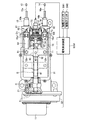
以下に、本発明の各実施形態を図面に基づいて説明する。図1〜図6は本発明の第1実施形態を示していて、この第1実施形態は自動車用の電動パーキングブレーキ装置に本発明を実施したものである。図1に示した電動パーキングブレーキ装置は、電気モータ11の出力である回転駆動力を減速して伝達する減速機構Aと、この減速機構Aを介して伝達される電気モータ11の回転駆動力を直線駆動力(直線的な駆動力)に変換する変換機構Bと、この変換機構Bにより変換された直線駆動力によって駆動されるとともに直線駆動力を二つの出力部に分配するイコライザ12を備えている。   Embodiments of the present invention will be described below with reference to the drawings. 1 to 6 show a first embodiment of the present invention, and this first embodiment is an embodiment of the present invention applied to an electric parking brake device for an automobile. The electric parking brake device shown in FIG. 1 decelerates and transmits the rotational driving force, which is the output of the electric motor 11, and the rotational driving force of the electric motor 11 transmitted through the speed reducing mechanism A. A conversion mechanism B that converts linear driving force (linear driving force) and an equalizer 12 that is driven by the linear driving force converted by the conversion mechanism B and distributes the linear driving force to two output units are provided. Yes.

また、電動パーキングブレーキ装置は、イコライザ12の各出力部12a,12bに連結されて直線駆動力を各パーキングブレーキ13,14に伝達する一対のケーブル15,16と、これら両ケーブル15,16におけるインナーワイヤ15a,16aに作用する引張力を検出可能で電気信号を出力する張力センサTSと、電気モータ11の回転駆動を制御する電気制御装置ECUを備えている。   The electric parking brake device is connected to the output portions 12 a and 12 b of the equalizer 12 to transmit a linear driving force to the parking brakes 13 and 14, and inner cables of these cables 15 and 16. A tension sensor TS that can detect a tensile force acting on the wires 15a and 16a and outputs an electric signal, and an electric control unit ECU that controls the rotational drive of the electric motor 11 are provided.

なお、減速機構Aと変換機構Bの連結部位には、ワンウェイ動力伝達機構Cが介装されている。ワンウェイ動力伝達機構Cは、ねじ軸41上に組付けられていて、電気モータ11および減速機構Aから変換機構Bへの回転駆動力は伝達するが、変換機構Bから減速機構Aへの回転駆動力の伝達は阻止して、電気モータ11の正回転駆動停止時に、パーキングブレーキ13,14の制動状態を保持可能である。   Note that a one-way power transmission mechanism C is interposed at a connecting portion between the speed reduction mechanism A and the conversion mechanism B. The one-way power transmission mechanism C is assembled on the screw shaft 41 and transmits the rotational driving force from the electric motor 11 and the speed reduction mechanism A to the conversion mechanism B, but the rotational drive from the conversion mechanism B to the speed reduction mechanism A. The transmission of force can be prevented, and the braking state of the parking brakes 13 and 14 can be maintained when the electric motor 11 is stopped from rotating forward.

電気モータ11は、車体の一部に固定保持されるハウジング31の一側に組付けたケーシング32に組付けられていて、電気制御装置ECUによって作動を制御されるようになっている。この電気モータ11は、例えば、運転者が制動スイッチSW1を操作することにより正方向に回転駆動され、運転者が解除スイッチSW2を操作することにより逆方向に回転駆動されるようになっている。   The electric motor 11 is assembled to a casing 32 that is assembled to one side of a housing 31 that is fixedly held on a part of the vehicle body, and its operation is controlled by the electric control unit ECU. For example, the electric motor 11 is rotated in the forward direction when the driver operates the brake switch SW1, and is rotated in the reverse direction when the driver operates the release switch SW2.

減速機構Aは、ハウジング31とケーシング32間の収容部内に組み込まれていて、電気モータ11の出力軸(図示省略)に組付けられて一体的に回転する入力小歯車(図示省略)と、ねじ軸41の端部に回転可能に組付けられてワンウェイ動力伝達機構Cの入力部にトルク伝達可能に連結されている出力大歯車21を備えている。また、減速機構Aは、ハウジング31とケーシング32に回転可能に組付けられて入力小歯車と常時噛合する中間大歯車(図示省略)と、この中間大歯車と一体的に回転可能であり出力大歯車21と常時噛合する中間小歯車(図示省略)を備えている。   The speed reduction mechanism A is incorporated in a housing portion between the housing 31 and the casing 32, and is connected to an output shaft (not shown) of the electric motor 11 and rotates integrally with an input small gear (not shown), a screw An output large gear 21 is rotatably attached to the end of the shaft 41 and connected to the input portion of the one-way power transmission mechanism C so as to be able to transmit torque. Further, the speed reduction mechanism A is rotatably assembled to the housing 31 and the casing 32, and an intermediate large gear (not shown) that is always meshed with the input small gear, and the intermediate large gear can rotate integrally with the intermediate large gear, and the output is large. An intermediate small gear (not shown) that always meshes with the gear 21 is provided.

変換機構Bは、ワンウェイ動力伝達機構Cの出力部にトルク伝達可能に連結されているねじ軸41を入力要素とし、このねじ軸41に螺合して組付けたナット42を出力要素とする構成であり、ねじ軸41が正方向に回転駆動されることによりナット42が図1右方の解除位置(図示実線位置)から図1左方の制動位置(図示仮想線位置)に向けてねじ軸41の軸線方向に移動され、また、ねじ軸41が逆方向に回転駆動されることによりナット42が図1右方の解除位置に向けてねじ軸41の軸線方向に移動されるようになっている。   The conversion mechanism B has a configuration in which a screw shaft 41 connected to an output portion of the one-way power transmission mechanism C is connected to be able to transmit torque as an input element, and a nut 42 screwed and assembled to the screw shaft 41 is used as an output element. When the screw shaft 41 is rotationally driven in the forward direction, the nut 42 is moved from the release position (shown in the solid line in FIG. 1) toward the brake position (shown in the phantom line in the drawing) on the left in FIG. The nut 42 is moved in the axial direction of the screw shaft 41 toward the release position on the right side in FIG. 1 when the screw shaft 41 is driven to rotate in the reverse direction. Yes.

ねじ軸41は、ケーブル15,16におけるインナーワイヤ15a,16aの移動方向を軸方向として配置されていて、雄ねじ(雄ねじの条数や形状は適宜変更可能である)を有しており、ハウジング31に対して軸方向に僅かに(張力センサTSにて両ケーブル15,16のインナーワイヤ15a,16aに作用する引張力を検出可能な程度に)移動可能かつ回転可能に組付けられている。ナット42は、連結ピン43を介してイコライザ12と連結されていて、イコライザ12を揺動可能(連結ピン43周りに回動可能)に支持している。なお、図1に示したハウジング31では、同ハウジング31の開口を密封するカバー(図示省略)が取り外されている。   The screw shaft 41 is arranged with the moving direction of the inner wires 15a, 16a in the cables 15, 16 as the axial direction, and has a male screw (the number and shape of the male screw can be changed as appropriate), and the housing 31 In contrast, it is assembled so as to be movable and rotatable slightly in the axial direction (so that the tensile force acting on the inner wires 15a and 16a of the cables 15 and 16 can be detected by the tension sensor TS). The nut 42 is connected to the equalizer 12 via the connecting pin 43 and supports the equalizer 12 so as to be able to swing (rotate around the connecting pin 43). In addition, in the housing 31 shown in FIG. 1, the cover (illustration omitted) which seals the opening of the housing 31 is removed.

イコライザ12は、ナット42に作用する直線駆動力を二つの出力部12a,12bに等分に分配するものであり、その中央部にてナット42に設定量(例えば、図1の状態から左右に20度程度)揺動可能に組付けられている。また、イコライザ12は、一方の出力部12aにて、一方のケーブル15におけるインナーワイヤ15aの一端部15a1と連結機構D1を介して連結され、他方の出力部12bにて、他方のケーブル16におけるインナーワイヤ16aの一端部16a1と連結機構D2を介して連結されている。   The equalizer 12 distributes the linear driving force acting on the nut 42 equally to the two output parts 12a and 12b, and a set amount (for example, left and right from the state of FIG. It is assembled so that it can swing. The equalizer 12 is connected to one end portion 15a1 of the inner wire 15a in one cable 15 through one connecting portion D1 at one output portion 12a, and to the inner portion in the other cable 16 at the other output portion 12b. It is connected to one end 16a1 of the wire 16a via a connecting mechanism D2.

一方のケーブル15は、インナーワイヤ15aと、このインナーワイヤ15aの両端部以外の外周を被覆し各端部を保持部材としてのハウジング31と一方のパーキングブレーキ13のブレーキハウジング(図示省略)により移動不能に保持されるアウターチューブ15bによって構成されていて、インナーワイヤ15aの他端部は、一方のパーキングブレーキ13の作動部に周知のようにして連結されている。   One cable 15 is immovable by an inner wire 15a, a housing 31 that covers the outer periphery other than both ends of the inner wire 15a, and each end is a holding member and a brake housing (not shown) of one parking brake 13. The other end portion of the inner wire 15a is connected to the operating portion of one parking brake 13 in a well-known manner.

他方のケーブル16は、インナーワイヤ16aと、このインナーワイヤ16aの両端部以外の外周を被覆し各端部を保持部材としてのハウジング31と他方のパーキングブレーキ14のブレーキハウジング(図示省略)により移動不能に保持されるアウターチューブ16bによって構成されていて、インナーワイヤ16aの他端部は、他方のパーキングブレーキ14の作動部に周知のようにして連結されている。   The other cable 16 is immovable by an inner wire 16a and an outer periphery other than both ends of the inner wire 16a and a housing 31 serving as a holding member at each end and a brake housing (not shown) of the other parking brake 14. The other end portion of the inner wire 16a is connected to the operating portion of the other parking brake 14 in a well-known manner.

張力センサTSは、ハウジング31の図1右端部に組付けられていて、ハウジング31にOリングを介して内側から嵌合固定されたケース51と、このケース51内に組付けられてクリップ52により抜け止めされた軸受プレート53、スラストベアリング54、プレッシャプレート55およびゴム製のディスク56と、ハウジング31にOリングを介して外側から嵌合されかつケース51に螺着されてディスク56の一部に当接しねじ軸41に作用する軸荷重の一部を検出する圧力センサ57等によって構成されている。   The tension sensor TS is assembled to the right end of the housing 31 in FIG. 1, and is fitted and fixed to the housing 31 from the inside via an O-ring, and the clip 51 is assembled to the case 51. The bearing plate 53, the thrust bearing 54, the pressure plate 55, and the rubber disk 56, which are prevented from coming off, are fitted to the housing 31 from the outside via an O-ring and screwed to the case 51 to be part of the disk 56. The pressure sensor 57 is configured to detect a part of the axial load that contacts and acts on the screw shaft 41.

この張力センサTSでは、ねじ軸41に作用する全軸荷重が、軸受プレート53、スラストベアリング54、プレッシャプレート55を介してディスク56に伝わり、ディスク56にてケース51と圧力センサ57に予め設定されている受圧面積比で分配されるため、圧力センサ57の出力に基づいて両ケーブル15,16のインナーワイヤ15a,16aに作用する引張力(ねじ軸41に作用する全軸荷重に相当する)を検出することが可能である。   In this tension sensor TS, the entire axial load acting on the screw shaft 41 is transmitted to the disk 56 through the bearing plate 53, the thrust bearing 54, and the pressure plate 55, and is preset in the case 51 and the pressure sensor 57 by the disk 56. Therefore, the tensile force acting on the inner wires 15a and 16a of the cables 15 and 16 based on the output of the pressure sensor 57 (corresponding to the total axial load acting on the screw shaft 41) is distributed. It is possible to detect.

一方の連結機構D1は、図1に示したように、イコライザ12における一方の出力部12aに連結ピン61を介して回動可能に連結された連結部材62と、この連結部材62と一方のケーブル15におけるインナーワイヤ15aの一端部15a1との連結部位に脱着可能に組付けられた回転抑止部材63を備えている。他方の連結機構D2は、図1に示したように、イコライザ12における他方の出力部12bに連結ピン71を介して回動可能に連結された連結部材72と、この連結部材72と他方のケーブル16におけるインナーワイヤ16aの一端部16a1との連結部位に脱着可能に組付けられた回転抑止部材73を備えている。   As shown in FIG. 1, one connecting mechanism D1 includes a connecting member 62 rotatably connected to one output portion 12a of the equalizer 12 via a connecting pin 61, and the connecting member 62 and one cable. 15 is provided with a rotation restraining member 63 that is detachably assembled to a connecting portion of the inner wire 15a with one end 15a1 of the inner wire 15a. As shown in FIG. 1, the other connecting mechanism D2 includes a connecting member 72 that is rotatably connected to the other output portion 12b of the equalizer 12 via a connecting pin 71, and the connecting member 72 and the other cable. 16 is provided with a rotation restraining member 73 which is detachably assembled to a connecting portion of the inner wire 16a with one end portion 16a1 of the inner wire 16a.

インナーワイヤ15aの一端部15a1と、インナーワイヤ16aの一端部16a1は、同一形状に形成されているため、インナーワイヤ15aの一端部15a1について詳細に説明し、インナーワイヤ16aの一端部16a1についての説明は省略する。インナーワイヤ15aの一端部15a1は、図2〜図5に示したように、インナーワイヤ15aの長手方向に延びる軸部xと、この軸部xの先端に一体的に設けられてインナーワイヤ15aの長手方向に対して直交するI字状連結部yを有していて、全体としてT字状(図4参照)とされている。   Since the one end 15a1 of the inner wire 15a and the one end 16a1 of the inner wire 16a are formed in the same shape, the one end 15a1 of the inner wire 15a will be described in detail, and the one end 16a1 of the inner wire 16a will be described. Is omitted. As shown in FIGS. 2 to 5, the one end portion 15 a 1 of the inner wire 15 a is integrally provided on the shaft portion x extending in the longitudinal direction of the inner wire 15 a and the tip of the shaft portion x. It has an I-shaped connecting portion y orthogonal to the longitudinal direction, and is generally T-shaped (see FIG. 4).

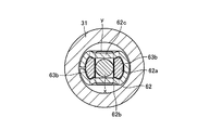
一方の連結部材62と、他方の連結部材72は、同一形状に形成されているため、一方の連結部材62について詳細に説明し、他方の連結部材72についての説明は省略する。一方の連結部材62は、図2、図4および図5に示したように、インナーワイヤ15aのI字状連結部yをインナーワイヤ15aの長手方向に挿通可能な挿通孔部62aと、この挿通孔部62aに挿通されて貫通したI字状連結部yの挿通孔周りの回転を許容する回転許容部62bと、挿通孔部62aに挿通されて貫通したI字状連結部yが回転許容部62bにて所定量(略90度)回転された状態でI字状連結部yとインナーワイヤ15aの長手方向にて係合可能な係合部62cとをワイヤ側端部に有している。   Since one connecting member 62 and the other connecting member 72 are formed in the same shape, one connecting member 62 will be described in detail, and description of the other connecting member 72 will be omitted. As shown in FIGS. 2, 4 and 5, one connecting member 62 includes an insertion hole 62a through which the I-shaped connecting portion y of the inner wire 15a can be inserted in the longitudinal direction of the inner wire 15a, and the insertion hole 62a. A rotation allowing portion 62b that allows rotation around the insertion hole of the I-shaped connecting portion y inserted through the hole portion 62a and an I-shaped connecting portion y that passes through the insertion hole portion 62a and passes therethrough are rotation-allowing portions. The wire-side end portion has an I-shaped connecting portion y and an engaging portion 62c that can be engaged in the longitudinal direction of the inner wire 15a while being rotated by a predetermined amount (approximately 90 degrees) at 62b.

また、一方の連結部材62のワイヤ側端部には、インナーワイヤ15aのI字状連結部yが挿通孔部62aに挿通されて貫通し挿通孔周りの回転を許容されたときにI字状連結部yが当接可能なストッパ部62dと、挿通孔部62aの端部からインナーワイヤ15aの長手方向に所定量延びる一対の突片部62eと、これら各突片部62eに形成されて回転抑止部材63の係止部63aが弾撥的に係合・離脱可能で回転抑止部材63を連結部材62に対して脱着可能とする一対の突起62fが設けられている。   Further, the I-shaped connecting portion y of the inner wire 15a is inserted into the insertion hole 62a at the wire side end of one of the connecting members 62 and is allowed to rotate around the insertion hole. A stopper portion 62d with which the connecting portion y can abut, a pair of protruding piece portions 62e extending in the longitudinal direction of the inner wire 15a from the end of the insertion hole portion 62a, and a rotation formed by these protruding piece portions 62e. A pair of protrusions 62 f are provided that allow the locking portion 63 a of the restraining member 63 to be elastically engaged and disengaged and to allow the rotation restraining member 63 to be attached to and detached from the connecting member 62.

一方の回転抑止部材63と、他方の回転抑止部材73は、同一形状に形成されているため、一方の回転抑止部材63について詳細に説明し、他方の回転抑止部材73についての説明は省略する。一方の回転抑止部材63は、図2、図4〜図6に示したように、連結部材62とインナーワイヤ15aの一端部15a1の連結部位に脱着可能に組付けられていて、I字状連結部yの所定量回転された状態を保持可能である。   Since one rotation suppression member 63 and the other rotation suppression member 73 are formed in the same shape, one rotation suppression member 63 will be described in detail, and description of the other rotation suppression member 73 will be omitted. As shown in FIGS. 2 and 4 to 6, one rotation restraining member 63 is detachably assembled to the connecting portion of the connecting member 62 and the one end portion 15 a 1 of the inner wire 15 a, and has an I-shaped connection. The state where the portion y is rotated by a predetermined amount can be held.

また、一方の回転抑止部材63は、インナーワイヤ15aの長手方向に対して直交する方向にて連結部材62の各突起62fに弾撥的に係合して抜け止めされかつ同弾撥的係合を解除された状態ではインナーワイヤ15aの長手方向に沿って移動可能な一対の係止部63aと、連結部材62の挿通孔部62aに挿通されて一部が貫通し貫通部分にてインナーワイヤ15aのI字状連結部yの回転を抑制する一対の抑制部63bとを一体的に備えている。また、一方の回転抑止部材63には、インナーワイヤ15aのI字状連結部yと連結部材62の両突片部62eが挿通可能な矩形孔63cが形成されるとともに、連結部材62の両突起62fが通過可能な一対の切欠63dが形成されている。   One rotation restraining member 63 is elastically engaged with each protrusion 62f of the connecting member 62 in a direction orthogonal to the longitudinal direction of the inner wire 15a and is prevented from coming off, and the elastic repulsive engagement. In the released state, the inner wire 15a is inserted through the pair of engaging portions 63a movable along the longitudinal direction of the inner wire 15a and the insertion hole portion 62a of the connecting member 62 and partially penetrates the inner wire 15a. And a pair of restraining portions 63b that restrain the rotation of the I-shaped connecting portion y. In addition, one rotation restraining member 63 is formed with a rectangular hole 63c into which the I-shaped connecting portion y of the inner wire 15a and both protruding pieces 62e of the connecting member 62 can be inserted, and both protrusions of the connecting member 62 A pair of notches 63d through which 62f can pass is formed.

また、この実施形態においては、各インナーワイヤ15a,16aの一端部15a1,16a1がハウジング31外からハウジング31を通してイコライザ12の各出力部12a,12bに各連結機構D1,D2を介して脱着可能である。また、各アウターチューブ15b,16bの一端部15b1,16b1が、ハウジング31に対してOリングを介して各インナーワイヤ15a,16aの長手方向に沿って抜き差し可能(脱着可能)であって、各アウターチューブ15b,16bの一端部15b1,16b1を覆う各チューブカバー81,82によってハウジング31に対して抜け止めされている。   Further, in this embodiment, one end portions 15a1 and 16a1 of the inner wires 15a and 16a can be attached to and detached from the output portions 12a and 12b of the equalizer 12 from the outside of the housing 31 through the housing 31 via the connecting mechanisms D1 and D2. is there. Further, one end portions 15b1 and 16b1 of the outer tubes 15b and 16b can be inserted into and removed from the housing 31 along the longitudinal direction of the inner wires 15a and 16a via an O-ring (removable). The tubes 15b and 16b are prevented from being detached from the housing 31 by tube covers 81 and 82 covering the one end portions 15b1 and 16b1.

一方のチューブカバー81と、他方のチューブカバー82は、同一形状に形成されているため、一方のチューブカバー81について詳細に説明し、他方のチューブカバー82についての説明は省略する。一方のチューブカバー81は、アウターチューブ15bの一端部15b1に組付けられた状態にてハウジング31に対して脱着可能であって、図2〜図4に示したように、アウターチューブ15bに対してその長手方向に直交する方向にて抜き差し可能とする切欠部81aと、アウターチューブ15bの外周の一部に嵌合して位置決めされる嵌合部81bと、ハウジング31に設けた一対の係止部31a(溝部)に脱着可能に係合する一対の係合部81c(爪部)を有している。   Since one tube cover 81 and the other tube cover 82 are formed in the same shape, the one tube cover 81 will be described in detail, and the description of the other tube cover 82 will be omitted. One tube cover 81 is detachable from the housing 31 in a state assembled to one end portion 15b1 of the outer tube 15b. As shown in FIGS. 2 to 4, the tube cover 81 is attached to the outer tube 15b. A notch portion 81a that can be inserted and removed in a direction orthogonal to the longitudinal direction, a fitting portion 81b that is fitted and positioned on a part of the outer periphery of the outer tube 15b, and a pair of locking portions provided in the housing 31 It has a pair of engaging part 81c (claw part) engaged with 31a (groove part) so that attachment or detachment is possible.

上記のように構成したこの第1実施形態においては、制動スイッチSW1が操作されると、電気モータ11が正回転駆動されて、変換機構Bのねじ軸41が正回転され、これに伴ってナット42とイコライザ12が図1の右方位置(解除位置)から図1の左方位置(制動位置)に向けてねじ軸41の軸方向に移動する。このため、両ケーブル15,16のインナーワイヤ15a,16aが引っ張られて両パーキングブレーキ13,14が解除状態から制動状態とされる。   In the first embodiment configured as described above, when the brake switch SW1 is operated, the electric motor 11 is driven to rotate in the forward direction, and the screw shaft 41 of the conversion mechanism B is rotated in the forward direction. 42 and the equalizer 12 move in the axial direction of the screw shaft 41 from the right position (release position) in FIG. 1 toward the left position (braking position) in FIG. For this reason, the inner wires 15a and 16a of the cables 15 and 16 are pulled, and the parking brakes 13 and 14 are changed from the released state to the braked state.

このとき(両ケーブル15,16のインナーワイヤ15a,16aが引っ張られるとき)には、張力センサTSにて、両ケーブル15,16のインナーワイヤ15a,16aに作用する引張力が検出される。この引張力は、電気制御装置ECUに入力され、その値が高設定値(制動判定値)になると、電気制御装置ECUからの制御信号に基づいて、電気モータ11の正回転駆動が停止される。なお、電気モータ11の正回転駆動停止時には、ねじ軸41の逆回転が変換機構B、ワンウェイ動力伝達機構Cおよび減速機構A等により規制されて保持されるため、両パーキングブレーキ13,14の制動状態が保持される。   At this time (when the inner wires 15a and 16a of both cables 15 and 16 are pulled), the tension force acting on the inner wires 15a and 16a of both cables 15 and 16 is detected by the tension sensor TS. This tensile force is input to the electric control unit ECU, and when the value reaches a high set value (braking determination value), the forward rotation drive of the electric motor 11 is stopped based on a control signal from the electric control unit ECU. . When the electric motor 11 stops rotating forward, the reverse rotation of the screw shaft 41 is regulated and held by the conversion mechanism B, the one-way power transmission mechanism C, the speed reduction mechanism A, etc. State is maintained.

また、上記した両パーキングブレーキ13,14の制動状態にて、解除スイッチSW2が操作されると、電気モータ11が逆回転駆動されて、変換機構Bのねじ軸41が逆回転され、これによりナット42とイコライザ12が図1の左方位置(制動位置)から図1の右方位置(解除位置)に移動する。このため、両ケーブル15,16のインナーワイヤ15a,16aが緩められて両パーキングブレーキ13,14が制動状態から解除状態とされる。   Further, when the release switch SW2 is operated in the braking state of both the parking brakes 13 and 14, the electric motor 11 is driven in reverse rotation, and the screw shaft 41 of the conversion mechanism B is rotated in reverse, whereby the nut 42 and the equalizer 12 move from the left position (braking position) in FIG. 1 to the right position (release position) in FIG. For this reason, the inner wires 15a and 16a of both the cables 15 and 16 are loosened, and both the parking brakes 13 and 14 are released from the braking state.

このとき(両ケーブル15,16のインナーワイヤ15a,16aが緩められるとき)にも、張力センサTSにて、両ケーブル15,16のインナーワイヤ15a,16aに作用する引張力が検出される。この引張力は、電気制御装置ECUに入力され、その値が低設定値(解除判定値)になると、電気制御装置ECUからの制御信号に基づいて、電気モータ11の逆回転駆動が停止される。   Also at this time (when the inner wires 15a and 16a of both cables 15 and 16 are loosened), the tension force acting on the inner wires 15a and 16a of both cables 15 and 16 is detected by the tension sensor TS. The tensile force is input to the electric control unit ECU, and when the value becomes a low set value (release determination value), the reverse rotation driving of the electric motor 11 is stopped based on the control signal from the electric control unit ECU. .

また、上記した第1実施形態においては、各チューブカバー81,82をハウジング31から取り外すこと(一対の係合部81c(爪部)をハウジング31に設けた一対の係止部31a(溝部)から外して引き抜くこと)で、各アウターチューブ15b,16bの一端部15b1,16b1を、ハウジング31から取り外すこと(各インナーワイヤ15a,16aの長手方向に沿って抜き取ること)ができる。   Further, in the first embodiment described above, the tube covers 81 and 82 are removed from the housing 31 (from a pair of locking portions 31a (grooves) provided with a pair of engaging portions 81c (claw portions) on the housing 31). The one end portions 15b1 and 16b1 of the outer tubes 15b and 16b can be removed from the housing 31 (withdrawn along the longitudinal direction of the inner wires 15a and 16a).

また、各チューブカバー81,82と各アウターチューブ15b,16bの一端部15b1,16b1をハウジング31から取り外した状態では、各連結部材62,72と各インナーワイヤ15a,16aの一端部15a1,16a1との連結部位から各回転抑止部材63,73を外した後に、各インナーワイヤ15a,16aの一端部15a1,16a1に設けたI字状連結部yを、各連結部材62,72の回転許容部(62b)にて各連結部材62,72の挿通孔部(62a)に合わせるまで回転させてインナーワイヤの長手方向に引き抜けば、各連結部材62,72と各インナーワイヤ15a,16aの結合を解いて、イコライザ12と各インナーワイヤ15a,16aの結合を解くことができる。なお、各回転抑止部材63,73は、一対の係止部(63a)を各連結部材62,72の各突起(62f)から外した状態で、インナーワイヤの長手方向に引き抜くことにより、上記した連結部位から外すことができる。   Further, in a state where the tube covers 81 and 82 and the one end portions 15b1 and 16b1 of the outer tubes 15b and 16b are removed from the housing 31, the connection members 62 and 72 and the end portions 15a1 and 16a1 of the inner wires 15a and 16a After the rotation restraining members 63 and 73 are removed from the connecting portions, the I-shaped connecting portions y provided on the one end portions 15a1 and 16a1 of the inner wires 15a and 16a are connected to the rotation permissible portions of the connecting members 62 and 72 ( 62b) until it is aligned with the insertion hole 62a of each connecting member 62, 72 and pulled out in the longitudinal direction of the inner wire, the connection between each connecting member 62, 72 and each inner wire 15a, 16a is released. Thus, the coupling between the equalizer 12 and each of the inner wires 15a and 16a can be released. In addition, each rotation suppression member 63, 73 is described above by pulling out in the longitudinal direction of the inner wire in a state where the pair of locking portions (63a) is removed from the projections (62f) of the connection members 62, 72. It can be removed from the connection site.

一方、各インナーワイヤ15a,16aの一端部15a1,16a1に設けたI字状連結部yを、イコライザ12に連結された各連結部材62,72の挿通孔部(62a)に挿通して貫通させ、I字状連結部yの左端がストッパ部62dに当接する程度まで押し込んだ状態で各連結部材62,72の回転許容部(62b)にて所定量(略90度)回転させた後に、各連結部材62,72と各インナーワイヤ15a,16aの一端部15a1,16a1との連結部位に各回転抑止部材63,73を組付けてI字状連結部yの所定量回転された状態を保持することで、イコライザ12と各インナーワイヤ15a,16aを結合させることができる。   On the other hand, the I-shaped connecting portion y provided at the one end portions 15a1 and 16a1 of the inner wires 15a and 16a is inserted through the insertion hole portions (62a) of the connecting members 62 and 72 connected to the equalizer 12, and penetrated. The I-shaped connecting portion y is rotated by a predetermined amount (approximately 90 degrees) in the rotation allowing portion (62b) of each connecting member 62, 72 in a state where the left end of the I-shaped connecting portion y is pushed to the extent that it abuts against the stopper portion 62d. The rotation restraining members 63 and 73 are assembled to the connecting portions of the connecting members 62 and 72 and the one end portions 15a1 and 16a1 of the inner wires 15a and 16a to maintain the state where the I-shaped connecting portion y is rotated by a predetermined amount. Thereby, the equalizer 12 and each inner wire 15a, 16a can be combined.

また、イコライザ12と各インナーワイヤ15a,16aを各連結機構D1,D2を介して結合させた状態では、各アウターチューブ15b,16bの一端部15b1,16b1を、ハウジング31に取り付けること(各インナーワイヤ15a,16aの長手方向に沿って嵌め込むこと)ができるとともに、各チューブカバー81,82をハウジング31に取り付けること(各チューブカバー81,82をハウジング31に嵌め込むことで、一対の係合部81c(爪部)をハウジング31に設けた一対の係止部31a(溝部)に係合させること)ができる。   Further, in a state where the equalizer 12 and the inner wires 15a and 16a are coupled via the coupling mechanisms D1 and D2, one end portions 15b1 and 16b1 of the outer tubes 15b and 16b are attached to the housing 31 (each inner wire 15a and 16a can be fitted along the longitudinal direction), and the tube covers 81 and 82 are attached to the housing 31 (by fitting the tube covers 81 and 82 into the housing 31, a pair of engaging portions 81c (claw portion) can be engaged with a pair of locking portions 31a (groove portions) provided in the housing 31).

ところで、この第1実施形態においては、イコライザ12と各インナーワイヤ15a,16aの結合状態で、各連結部材62,72の係合部(62c)と各インナーワイヤ15a,16aのI字状連結部yがインナーワイヤの長手方向にて係合可能であり、しかも、各I字状連結部yの所定量回転された状態が各回転抑止部材63,73により保持可能であるため、各インナーワイヤ15a,16aに引張り力が作用するときにも、各インナーワイヤ15a,16aのI字状連結部yがイコライザ12に連結された各連結部材62,72に対して回転し難く、イコライザ12と各インナーワイヤ15a,16aの結合状態での信頼性が極めて高いものである。   By the way, in this 1st Embodiment, in the connection state of the equalizer 12 and each inner wire 15a, 16a, the engaging part (62c) of each connection member 62,72 and the I-shaped connection part of each inner wire 15a, 16a Since y can be engaged in the longitudinal direction of the inner wire, and the state where each I-shaped connecting portion y is rotated by a predetermined amount can be held by each rotation restraining member 63, 73, each inner wire 15a. 16a, the I-shaped connecting portion y of each inner wire 15a, 16a is difficult to rotate with respect to each connecting member 62, 72 connected to the equalizer 12, and the equalizer 12 and each inner wire 15a, 16a are not easily rotated. The reliability in the coupled state of the wires 15a and 16a is extremely high.

また、この第1実施形態においては、各回転抑止部材63,73が、インナーワイヤの長手方向に対して直交する方向にて各連結部材62,72の突起(62f)に弾撥的に係合して抜け止めされかつ同弾撥的係合を解除された状態ではインナーワイヤの長手方向に沿って移動可能な係止部(63a)と、各連結部材62,72の挿通孔部(62a)に挿通されて一部が貫通し貫通部分にてI字状連結部yの回転を抑制する抑制部(63b)とを一体的に備えている。このため、イコライザ12と各インナーワイヤ15a,16aのI字状連結部yを連結する信頼性が極めて高い各連結機構D1,D2を、各連結部材62,72と各回転抑止部材63,73の二部品にて構成することが可能であり、シンプルかつ安価に構成することが可能である。   In the first embodiment, the rotation restraining members 63 and 73 are elastically engaged with the protrusions (62f) of the connecting members 62 and 72 in a direction orthogonal to the longitudinal direction of the inner wire. In the state where the stopper is released and the elastic repellent engagement is released, the engaging portion (63a) movable along the longitudinal direction of the inner wire, and the insertion hole portion (62a) of each of the connecting members 62, 72 And a suppression portion (63b) that is partially penetrated and that suppresses the rotation of the I-shaped coupling portion y at the penetration portion. For this reason, the highly reliable connection mechanisms D1 and D2 for connecting the equalizer 12 and the I-shaped connection portions y of the inner wires 15a and 16a are connected to the connection members 62 and 72 and the rotation suppression members 63 and 73, respectively. It can be configured with two parts, and can be configured simply and inexpensively.

また、この第1実施形態においては、上述したように、各インナーワイヤ15a,16aのI字状連結部y(一端部)が、ハウジング31外からハウジング31に挿入されて、ハウジング31内のイコライザ12の各出力部12a,12bに各連結機構D1,D2を介して脱着可能であり、かつ、各アウターチューブ15b,16bの一端部15b1,16b1がハウジング31に対して脱着可能である。   In the first embodiment, as described above, the I-shaped connecting portion y (one end portion) of each of the inner wires 15a and 16a is inserted into the housing 31 from the outside of the housing 31, and the equalizer in the housing 31 is inserted. The twelve output portions 12a and 12b can be attached to and detached from each other via the connecting mechanisms D1 and D2, and the one end portions 15b1 and 16b1 of the outer tubes 15b and 16b can be attached to and detached from the housing 31.

しかも、各アウターチューブ15b,16bの一端部15b1,16b1はハウジング31に対してインナーワイヤの長手方向に沿って抜き差し可能であり、各アウターチューブ15b,16bの一端部15b1,16b1を覆う各チューブカバー81,82は、ハウジング31に対して脱着可能であって、ハウジング31に組付けられた状態では各アウターチューブ15b,16bの一端部15b1,16b1をハウジング31に対して抜け止めする。また、各チューブカバー81,82は、各アウターチューブ15b,16bに対してその長手方向に直交する方向にて抜き差し可能とする切欠部(81a)と、各アウターチューブ15b,16bの外周の一部に嵌合して位置決めされる嵌合部(81b)と、ハウジング31に設けた係止部31aに脱着可能に係合する係合部(81c)を有している。   Moreover, the end portions 15b1 and 16b1 of the outer tubes 15b and 16b can be inserted into and removed from the housing 31 along the longitudinal direction of the inner wire, and the tube covers that cover the end portions 15b1 and 16b1 of the outer tubes 15b and 16b. Reference numerals 81 and 82 are detachable from the housing 31, and prevent the end portions 15 b 1 and 16 b 1 of the outer tubes 15 b and 16 b from coming off from the housing 31 when assembled to the housing 31. Each tube cover 81, 82 has a notch portion (81a) that can be inserted into and removed from each outer tube 15b, 16b in a direction perpendicular to the longitudinal direction, and a part of the outer periphery of each outer tube 15b, 16b. A fitting portion (81b) that is fitted and positioned on the housing 31 and an engaging portion (81c) that is detachably engaged with a locking portion 31a provided on the housing 31.

このため、ハウジング31への各種部品の組付後において、各ケーブル15,16におけるハウジング側端部の組付を該当部分の構成部品(各インナーワイヤ15a,16a、各アウターチューブ15b,16b、各回転抑制部材63,73、各チューブカバー81,82)のみの組付で行うことが可能であり、電動パーキングブレーキ装置あるいは車両の生産ラインにおいて各ケーブル15,16は途中工程でハウジング31に組付けた状態で取り扱う必要がないため、生産性が極めてよい。また、各ケーブル15,16におけるハウジング側端部の脱着(分解・再組付)が、ハウジング31を分解することなく、該当部分の構成部品のみの脱着で可能であり、市場でのサービス性が極めてよい。   For this reason, after assembling the various parts to the housing 31, the assembly of the housing side end portions of the cables 15 and 16 is made up of the corresponding component parts (inner wires 15a and 16a, outer tubes 15b and 16b, The rotation restraining members 63 and 73 and the tube covers 81 and 82) can be assembled, and the cables 15 and 16 are assembled to the housing 31 in the middle of the electric parking brake device or the vehicle production line. Productivity is extremely good because there is no need to handle it in a wet state. Moreover, the attachment / detachment (disassembly / reassembly) of the housing side end of each cable 15, 16 can be performed by attaching / detaching only the components of the corresponding part without disassembling the housing 31, and the serviceability in the market is improved. Very good.

上記した第1実施形態においては、インナーワイヤの長手方向に対して直交する方向にて各連結部材62,72の突起(62f)に弾撥的に係合して抜け止めされかつ同弾撥的係合を解除された状態ではインナーワイヤの長手方向に沿って移動可能な係止部(63a)と、各連結部材62,72の挿通孔部(62a)に挿通されて一部が貫通し貫通部分にてI字状連結部yの回転を抑制する抑制部(63b)とを一体的に備える各回転抑止部材63,73を採用して実施したが、図7〜図9に示した第2実施形態のように、各連結部材62,72に代えて連結部材162を採用するとともに、各回転抑止部材63,73に代えて回転抑止部材163を採用して実施することも可能である。   In the first embodiment described above, the protrusions (62f) of the connecting members 62 and 72 are elastically engaged with each other in the direction orthogonal to the longitudinal direction of the inner wire to prevent the inner wires from coming off and In a state where the engagement is released, the engaging portion (63a) movable along the longitudinal direction of the inner wire and the insertion hole portion (62a) of each of the connecting members 62 and 72 are partially penetrated and penetrated. The rotation restraining members 63 and 73 that are integrally provided with a restraining portion (63b) that restrains the rotation of the I-shaped connecting portion y at the portion are employed, but the second shown in FIGS. As in the embodiment, the connection member 162 may be used instead of the connection members 62 and 72, and the rotation suppression member 163 may be used instead of the rotation suppression members 63 and 73.

第2実施形態の連結部材162は、上記した第1実施形態の突片部62eと突起62fを備えていないことを除いて、第1実施形態の連結部材62と実質的に同じ構成であり、インナーワイヤ15aのI字状連結部yをインナーワイヤ15aの長手方向に挿通可能な挿通孔部162aと、この挿通孔部162aに挿通されて貫通したI字状連結部yの挿通孔周りの回転を許容する回転許容部162bと、挿通孔部162aに挿通されて貫通したI字状連結部yが回転許容部162bにて所定量(略90度)回転された状態でI字状連結部yとインナーワイヤ15aの長手方向にて係合可能な係合部162cとをワイヤ側端部に有するとともに、インナーワイヤ15aのI字状連結部yが挿通孔部162aに挿通されて貫通した状態で当接可能なストッパ部162dをワイヤ側端部に有している。このため、I字状連結部yは、ストッパ部162dに当接する程度に押し込まれた状態で、挿通孔部162a周りの回転が許容される。   The connecting member 162 of the second embodiment has substantially the same configuration as the connecting member 62 of the first embodiment, except that it does not include the protruding piece portion 62e and the protrusion 62f of the first embodiment described above. An insertion hole 162a through which the I-shaped connecting portion y of the inner wire 15a can be inserted in the longitudinal direction of the inner wire 15a, and rotation around the insertion hole of the I-shaped connecting portion y inserted through the insertion hole 162a. And the I-shaped connecting portion y in a state where the I-shaped connecting portion y inserted through the insertion hole 162a and rotated therethrough is rotated by a predetermined amount (approximately 90 degrees) by the rotation allowing portion 162b. And an engaging portion 162c that can be engaged in the longitudinal direction of the inner wire 15a at the wire side end, and the I-shaped connecting portion y of the inner wire 15a is inserted through the insertion hole 162a and penetrates therethrough. Abutable And a stopper portion 162d on the wire end. For this reason, the I-shaped connecting portion y is allowed to rotate around the insertion hole 162a in a state where the I-shaped connecting portion y is pushed to such an extent that it contacts the stopper portion 162d.

第2実施形態の回転抑止部材163は、インナーワイヤ15aの長手方向に対して直交する方向にてインナーワイヤ15aに設けた環状突起zに弾撥的に係合して抜け止めされかつ同弾撥的係合を解除された状態ではインナーワイヤ15aの長手方向に沿って移動可能な一対の係止部163aと、連結部材162の挿通孔部162aに挿通されて一部が貫通し貫通部分にてインナーワイヤ15aのI字状連結部yの回転を抑制する一対の抑制部163bとを一体的に備えている。また、回転抑止部材163には、インナーワイヤ15aのI字状連結部yが挿通可能な矩形孔163cが形成されている。   The rotation restraining member 163 of the second embodiment is elastically engaged with an annular protrusion z provided on the inner wire 15a in a direction orthogonal to the longitudinal direction of the inner wire 15a and is prevented from coming off. In a state where the general engagement is released, a pair of engaging portions 163a movable along the longitudinal direction of the inner wire 15a and an insertion hole portion 162a of the connecting member 162 are inserted, and a part thereof penetrates at a through portion. A pair of restraining portions 163b that restrains the rotation of the I-shaped connecting portion y of the inner wire 15a are integrally provided. Further, the rotation inhibiting member 163 is formed with a rectangular hole 163c into which the I-shaped connecting portion y of the inner wire 15a can be inserted.

図7〜図9に示した第2実施形態においては、チューブカバー81をハウジング31から取り外すことにより、アウターチューブ15bの一端部15b1をハウジング31から抜き取ることが可能である。また、アウターチューブ15bの一端部15b1をハウジング31から抜き取った状態で、一対の係止部163aを拡げて環状突起zとの係合を解除することにより、回転抑止部材163をハウジング31内から取り出すことが可能である。更に、この状態にてインナーワイヤ15aのI字状連結部yを略90度回転させて引き抜くことにより、インナーワイヤ15aを連結部材162から抜き取ることが可能である。このため、この第2実施形態においても、上記した第1実施形態と同様の作用効果が得られる。   In the second embodiment shown in FIGS. 7 to 9, it is possible to remove the one end 15 b 1 of the outer tube 15 b from the housing 31 by removing the tube cover 81 from the housing 31. Further, in a state where the one end portion 15b1 of the outer tube 15b is extracted from the housing 31, the pair of locking portions 163a are expanded to release the engagement with the annular protrusion z, whereby the rotation restraining member 163 is taken out from the housing 31. It is possible. Furthermore, in this state, the inner wire 15a can be extracted from the connecting member 162 by rotating the I-shaped connecting portion y of the inner wire 15a by approximately 90 degrees and pulling it out. For this reason, also in this 2nd Embodiment, the effect similar to above-mentioned 1st Embodiment is acquired.

また、上記した第1実施形態においては、各アウターチューブ15b,16bの一端部15b1,16b1がこれを覆う各チューブカバー81,82によってハウジング31に対して抜け止めされているが、図10〜図13に示した第3実施形態のように、各チューブカバー81,82に代えてホーク状部材281を採用して実施することも可能である。また、図10〜図13に示した第3実施形態においては、上記した第1実施形態の各連結部材62,72に代えて連結部材262が採用されるとともに、上記した第1実施形態の各回転抑止部材63,73に代えて回転抑止部材263が採用されている。   Further, in the first embodiment described above, the end portions 15b1 and 16b1 of the outer tubes 15b and 16b are prevented from being detached from the housing 31 by the tube covers 81 and 82 covering the outer ends 15b1 and 16b1, respectively. As in the third embodiment shown in FIG. 13, it is possible to employ a hawk-like member 281 instead of the tube covers 81 and 82. In addition, in the third embodiment shown in FIGS. 10 to 13, a connecting member 262 is employed instead of the connecting members 62 and 72 of the first embodiment, and each of the first embodiment described above. Instead of the rotation suppression members 63 and 73, a rotation suppression member 263 is adopted.

第3実施形態のホーク状部材281は、ハウジング231に対して脱着可能であり、一対の脚部281aにてハウジング231に設けた一対のスリット231aに差し込まれている。各脚部281aは、その中間部分にてハウジング231に嵌合されたアウターチューブ215bの一端部215b1と当接可能であって、アウターチューブ215bの一端部215b1を抜け止めしている。また、各脚部281aの先端部には、ハウジング231に係合可能な爪部281a1が設けられていて、この爪部281a1によってホーク状部材281がハウジング231に対して抜け止めされている。   The fork-like member 281 of the third embodiment is detachable from the housing 231 and is inserted into a pair of slits 231a provided in the housing 231 by a pair of legs 281a. Each leg portion 281a can abut on one end portion 215b1 of the outer tube 215b fitted to the housing 231 at an intermediate portion thereof, and prevents the end portion 215b1 of the outer tube 215b from coming off. Further, a claw portion 281a1 that can be engaged with the housing 231 is provided at the tip end portion of each leg portion 281a, and the fork-like member 281 is prevented from coming off from the housing 231 by the claw portion 281a1.

第3実施形態の連結部材262は、インナーワイヤ15aのI字状連結部yをインナーワイヤ15aの長手方向に挿通可能な挿通孔部262aと、この挿通孔部262aに挿通されて貫通したI字状連結部yの挿通孔周りの回転を許容する回転許容部262bと、挿通孔部262aに挿通されて貫通したI字状連結部yが回転許容部262bにて所定量(略90度)回転された状態でI字状連結部yとインナーワイヤ15aの長手方向にて係合可能な係合部262cとをワイヤ側端部に有している。また、連結部材262には、インナーワイヤ15aのI字状連結部yが挿通孔部262aに挿通されて貫通した状態で当接可能なストッパプレート262dが固着されている。このため、I字状連結部yは、ストッパプレート262dに当接する程度に押し込まれた状態で、挿通孔部262a周りの回転が許容される。   The connecting member 262 according to the third embodiment includes an insertion hole portion 262a through which the I-shaped connection portion y of the inner wire 15a can be inserted in the longitudinal direction of the inner wire 15a, and an I-shape inserted through the insertion hole portion 262a. Rotation permitting portion 262b allowing rotation around the insertion hole of the connecting portion y, and I-shaped connecting portion y inserted through the insertion hole portion 262a rotate by a predetermined amount (approximately 90 degrees) at the rotation allowing portion 262b. In this state, the I-shaped connecting portion y and the engaging portion 262c that can be engaged in the longitudinal direction of the inner wire 15a are provided at the wire side end portion. In addition, a stopper plate 262d that can come into contact with the I-shaped connecting portion y of the inner wire 15a through the insertion hole 262a is fixed to the connecting member 262. For this reason, the I-shaped connecting portion y is allowed to rotate around the insertion hole 262a in a state where the I-shaped connecting portion y is pushed to such an extent that it contacts the stopper plate 262d.

第3実施形態の回転抑止部材263は、インナーワイヤ15aの長手方向に対して直交する方向にて連結部材262に設けた係合孔262eに弾撥的に係合して抜け止めされかつ同弾撥的係合を解除された状態ではインナーワイヤ15aの長手方向に沿って移動可能な一対の係止部263aと、連結部材262の挿通孔部262aに挿通されて一部が貫通し貫通部分にてインナーワイヤ15aのI字状連結部yの回転を抑制する一対の抑制部263bとを一体的に備えている。また、回転抑止部材263には、インナーワイヤ15aのI字状連結部yが挿通可能な挿通孔263cが形成されるとともに、上記した各係止部263aと連結部材262の係合孔262eとの係合を解除させるための一対の操作レバー部263dが形成されている。   The rotation restraining member 263 of the third embodiment is elastically engaged with an engagement hole 262e provided in the connecting member 262 in a direction orthogonal to the longitudinal direction of the inner wire 15a and is prevented from coming off. In a state where the repellent engagement is released, a pair of engaging portions 263a movable along the longitudinal direction of the inner wire 15a and an insertion hole portion 262a of the connecting member 262 are inserted and partially penetrated into the through portion. And a pair of suppressing portions 263b that suppress the rotation of the I-shaped connecting portion y of the inner wire 15a. Further, the rotation restraining member 263 is formed with an insertion hole 263c through which the I-shaped connecting portion y of the inner wire 15a can be inserted, and between the above-described locking portions 263a and the engaging holes 262e of the connecting member 262. A pair of operation lever portions 263d for releasing the engagement is formed.

図10〜図13に示した第3実施形態においては、ホーク状部材281をハウジング231から抜き取ることにより、アウターチューブ215bの一端部215b1をハウジング231から抜き取ることが可能である。また、アウターチューブ215bの一端部215b1をハウジング231から抜き取った状態で、一対の操作レバー部263dを近づけて各係止部263aと係合孔262eとの係合を解除することにより、回転抑止部材263をハウジング231内から取り出すことが可能である。更に、この状態にてインナーワイヤ15aのI字状連結部yを略90度回転させて引き抜くことにより、インナーワイヤ15aを連結部材262から抜き取ることが可能である。このため、この第3実施形態においても、上記した第1実施形態と同様の作用効果が得られる。   In the third embodiment shown in FIGS. 10 to 13, the one end 215 b 1 of the outer tube 215 b can be extracted from the housing 231 by extracting the hawk-like member 281 from the housing 231. Further, in a state where the one end portion 215b1 of the outer tube 215b is removed from the housing 231, the pair of operation lever portions 263d are brought close to each other to release the engagement between the locking portions 263a and the engagement holes 262e, thereby preventing the rotation suppression member. 263 can be taken out of the housing 231. Further, in this state, the inner wire 15a can be extracted from the connecting member 262 by rotating the I-shaped connecting portion y of the inner wire 15a by approximately 90 degrees and pulling it out. For this reason, also in this 3rd Embodiment, the same operation effect as above-mentioned 1st Embodiment is acquired.

上記した各実施形態においては、本発明によるケーブル伝達機構を車両用パーキングブレーキ装置に適用したが、本発明によるケーブル伝達機構は車両用パーキングブレーキ装置以外の種々な作動機器にも上記実施形態と同様にまたは適宜変更して実施することが可能である。   In each of the above-described embodiments, the cable transmission mechanism according to the present invention is applied to the vehicle parking brake device. However, the cable transmission mechanism according to the present invention is also applicable to various operating devices other than the vehicle parking brake device. It is possible to carry out by carrying out or changing suitably.

本発明によるケーブル伝達機構を車両用パーキングブレーキ装置に適用した第1実施形態の一部破断平面図である。1 is a partially broken plan view of a first embodiment in which a cable transmission mechanism according to the present invention is applied to a vehicle parking brake device. 図1の要部拡大平面図である。It is a principal part enlarged plan view of FIG. 図2の3−3線に沿った断面図である。FIG. 3 is a cross-sectional view taken along line 3-3 in FIG. 2. 図2の4−4線に沿った断面図である。FIG. 4 is a cross-sectional view taken along line 4-4 of FIG. 図4の5−5線に沿った断面図である。FIG. 5 is a cross-sectional view taken along line 5-5 of FIG. 図1、図2、図4および図5に示した回転抑止部材単体の部分正面図である。FIG. 6 is a partial front view of a single rotation suppression member shown in FIGS. 1, 2, 4, and 5. 本発明の第2実施形態を示す図2相当の要部拡大平面図である。It is a principal part enlarged plan view equivalent to FIG. 2 which shows 2nd Embodiment of this invention. 図7に示した第2実施形態の図4相当の断面図である。It is sectional drawing equivalent to FIG. 4 of 2nd Embodiment shown in FIG. 図7および図8に示した回転抑止部材単体の部分正面図である。It is a partial front view of the rotation suppression member single-piece | unit shown in FIG. 7 and FIG. 本発明の第3実施形態を示す図2相当の要部拡大平面図である。It is a principal part enlarged plan view equivalent to FIG. 2 which shows 3rd Embodiment of this invention. 図10に示した第3実施形態の図4相当の断面図である。It is sectional drawing equivalent to FIG. 4 of 3rd Embodiment shown in FIG. 図10および図11に示したハウジングとホーク状部材の関係を示す図である。It is a figure which shows the relationship between the housing shown in FIG.10 and FIG.11, and a hawk-shaped member. 図10および図11に示した回転抑止部材単体の部分正面図である。It is a partial front view of the rotation suppression member simple substance shown in FIG. 10 and FIG.

符号の説明Explanation of symbols

12…イコライザ(駆動部材)、12a,12b…出力部、13,14…パーキングブレーキ(作動部材)、15,16…ケーブル、15a…インナーワイヤ、15a1…インナーワイヤの一端部、y…I字状連結部、15b…アウターチューブ、15b1…アウターチューブの一端部、31…ハウジング、D1,D2…連結機構、62…連結部材、62a…挿通孔部、62b…回転許容部、62c…係合部、63…回転抑制部材、63a…係止部、63b…抑制部、81…チューブカバー、81a…切欠部、81b…嵌合部、81c…係合部 DESCRIPTION OF SYMBOLS 12 ... Equalizer (drive member), 12a, 12b ... Output part, 13, 14 ... Parking brake (operation member), 15, 16 ... Cable, 15a ... Inner wire, 15a1 ... One end part of an inner wire, y ... I shape Connection part, 15b ... Outer tube, 15b1 ... One end part of outer tube, 31 ... Housing, D1, D2 ... Connection mechanism, 62 ... Connection member, 62a ... Insertion hole part, 62b ... Rotation permission part, 62c ... Engagement part, 63 ... Rotation suppression member, 63a ... Locking portion, 63b ... Suppression portion, 81 ... Tube cover, 81a ... Notch portion, 81b ... Fitting portion, 81c ... engagement portion

Claims (5)

駆動部材(12)と作動部材(13)間に介装されて前記駆動部材(12)から前記作動部材(13)に引張り力を伝達可能なケーブル(15)が、前記駆動部材(12)に連結機構(D1)を介して一端部(15a1)にて連結されるとともに他端部にて前記作動部材(13)に連結されるインナーワイヤ(15a)と、このインナーワイヤ(15a)の両端部以外の外周を被覆し各端部を保持部材により移動不能に保持されるアウターチューブ(15b)を備えているケーブル伝達機構において、
前記インナーワイヤ(15a)の一端部(15a1)には、同インナーワイヤ(15a)の長手方向に対して直交するI字状連結部(y)が一体的に設けられていて、
前記連結機構(D1)が、前記I字状連結部(y)を前記インナーワイヤ(15a)の長手方向に挿通可能な挿通孔部(62a)と、この挿通孔部(62a)に挿通されて貫通した前記I字状連結部(y)の挿通孔周りの回転を許容する回転許容部(62b)と、前記挿通孔部(62a)に挿通されて貫通した前記I字状連結部(y)が前記回転許容部(62b)にて所定量回転された状態で前記I字状連結部(y)と前記インナーワイヤ(15a)の長手方向にて係合可能な係合部(62c)とをワイヤ側端部に有して、駆動側端部にて前記駆動部材(12)に連結される連結部材(62)を備えるとともに、この連結部材(62)と前記インナーワイヤ(15a)の一端部(15a1)の連結部位に脱着可能に組付けられて、前記I字状連結部(y)の所定量回転された状態を保持可能な回転抑止部材(63)を備えていることを特徴とするケーブル伝達機構。
A cable (15) interposed between the drive member (12) and the actuating member (13) and capable of transmitting a tensile force from the drive member (12) to the actuating member (13) is provided to the drive member (12). An inner wire (15a) connected at one end (15a1) via the connecting mechanism (D1) and connected to the actuating member (13) at the other end, and both ends of the inner wire (15a) In the cable transmission mechanism provided with an outer tube (15b) that covers the outer periphery other than and has each end held immovably by a holding member,
An I-shaped connecting portion (y) orthogonal to the longitudinal direction of the inner wire (15a) is integrally provided at one end (15a1) of the inner wire (15a),
The connection mechanism (D1) is inserted through the insertion hole (62a) through which the I-shaped connection (y) can be inserted in the longitudinal direction of the inner wire (15a) and the insertion hole (62a). A rotation allowing portion (62b) that allows rotation of the penetrating I-shaped connecting portion (y) around the insertion hole, and the I-shaped connecting portion (y) that is inserted through the inserting hole portion (62a) and passes therethrough. The I-shaped connecting portion (y) and the engaging portion (62c) that can be engaged in the longitudinal direction of the inner wire (15a) with the rotation allowing portion (62b) rotated by a predetermined amount. A connecting member (62) that is provided at the wire side end and is connected to the driving member (12) at the driving side end, and one end of the connecting member (62) and the inner wire (15a). (15a1) is detachably assembled to the connecting portion, and the I-shaped Cable transmission mechanism, characterized in that it comprises forming unit capable of holding rotation inhibiting member a predetermined amount of rotation state of (y) (63).
請求項1に記載のケーブル伝達機構において、前記回転抑止部材(63)は、前記インナーワイヤ(15a)の長手方向に対して直交する方向にて前記連結部材(62)の一部または前記インナーワイヤ(15a)の一部に弾撥的に係合して抜け止めされかつ同弾撥的係合を解除された状態では前記インナーワイヤ(15a)の長手方向に沿って移動可能な係止部(63a)と、前記挿通孔部(62a)に挿通されて一部が貫通し貫通部分にて前記I字状連結部(y)の回転を抑制する抑制部(63b)とを一体的に備えていることを特徴とするケーブル伝達機構。   The cable transmission mechanism according to claim 1, wherein the rotation restraining member (63) is a part of the connecting member (62) or the inner wire in a direction orthogonal to a longitudinal direction of the inner wire (15a). A locking portion (15a) that is movable along the longitudinal direction of the inner wire (15a) in a state in which it is elastically engaged with a part of (15a) and is prevented from coming off and released. 63a) and a suppression portion (63b) that is inserted through the insertion hole portion (62a) and partially penetrates and suppresses the rotation of the I-shaped connection portion (y) at the penetration portion. A cable transmission mechanism characterized by that. 請求項1または2に記載のケーブル伝達機構において、前記作動部材(13)は車両用パーキングブレーキの作動部に設けられており、前記駆動部材(12)は車体に組付けられるハウジング(31)内に組付けられてパーキングブレーキ操作に伴って生じる駆動力を出力部(12a)にて出力可能であり、前記インナーワイヤ(15a)の一端部(15a1)は前記ハウジング(31)外から前記ハウジング(31)を通して前記駆動部材の出力部(12a)に前記連結機構(D1)を介して脱着可能であり、前記アウターチューブ(15b)の一端部(15b1)は前記ハウジング(31)に対して脱着可能であることを特徴とするケーブル伝達機構。   The cable transmission mechanism according to claim 1 or 2, wherein the operating member (13) is provided in an operating portion of a vehicle parking brake, and the driving member (12) is provided in a housing (31) assembled to a vehicle body. The driving force generated by the parking brake operation can be output at the output portion (12a), and one end portion (15a1) of the inner wire (15a) is connected to the housing (31) from the outside of the housing (31). 31) can be attached to and detached from the output part (12a) of the driving member through the connecting mechanism (D1) through the connecting part (D1), and one end part (15b1) of the outer tube (15b) can be attached to and detached from the housing (31). A cable transmission mechanism characterized by being. 請求項3に記載のケーブル伝達機構において、前記アウターチューブ(15b)の一端部(15b1)は前記ハウジング(31)に対して前記インナーワイヤ(15a)の長手方向に沿って抜き差し可能であり、前記アウターチューブ(15b)の一端部(15b1)を覆うチューブカバー(81)は前記ハウジング(31)に対して脱着可能であって前記ハウジング(31)に組付けられた状態では前記アウターチューブ(15b)の一端部(15b1)を前記ハウジング(31)に対して抜け止めすることを特徴とするケーブル伝達機構。   The cable transmission mechanism according to claim 3, wherein one end (15b1) of the outer tube (15b) is detachable along the longitudinal direction of the inner wire (15a) with respect to the housing (31), A tube cover (81) that covers one end (15b1) of the outer tube (15b) is detachable from the housing (31), and the outer tube (15b) is attached to the housing (31). One end portion (15b1) of the cable is prevented from coming off from the housing (31). 請求項4に記載のケーブル伝達機構において、前記チューブカバー(81)は、前記アウターチューブ(15b)に対してその長手方向に直交する方向にて抜き差し可能とする切欠部(81a)と、前記アウターチューブ(15b)の外周の一部に嵌合して位置決めされる嵌合部(81b)と、前記ハウジング(31)に設けた係止部(31a)に脱着可能に係合する係合部(81c)を有していることを特徴とするケーブル伝達機構。   5. The cable transmission mechanism according to claim 4, wherein the tube cover (81) is capable of being inserted into and removed from the outer tube (15 b) in a direction perpendicular to the longitudinal direction thereof, and the outer cover (81 a). A fitting portion (81b) that is positioned by being fitted to a part of the outer periphery of the tube (15b), and an engaging portion that is detachably engaged with a locking portion (31a) provided in the housing (31). 81c). A cable transmission mechanism characterized by comprising:
JP2007277245A 2007-10-25 2007-10-25 Cable transmission mechanism Pending JP2009103263A (en)

Priority Applications (1)

Application Number Priority Date Filing Date Title
JP2007277245A JP2009103263A (en) 2007-10-25 2007-10-25 Cable transmission mechanism

Applications Claiming Priority (1)

Application Number Priority Date Filing Date Title
JP2007277245A JP2009103263A (en) 2007-10-25 2007-10-25 Cable transmission mechanism

Publications (1)

Publication Number Publication Date
JP2009103263A true JP2009103263A (en) 2009-05-14

Family

ID=40705131

Family Applications (1)

Application Number Title Priority Date Filing Date
JP2007277245A Pending JP2009103263A (en) 2007-10-25 2007-10-25 Cable transmission mechanism

Country Status (1)

Country Link
JP (1) JP2009103263A (en)

Cited By (1)

* Cited by examiner, † Cited by third party
Publication number Priority date Publication date Assignee Title
JP2009166566A (en) * 2008-01-11 2009-07-30 Advics Co Ltd Vehicular electric parking brake device

Cited By (1)

* Cited by examiner, † Cited by third party
Publication number Priority date Publication date Assignee Title
JP2009166566A (en) * 2008-01-11 2009-07-30 Advics Co Ltd Vehicular electric parking brake device

Similar Documents

Publication Publication Date Title
US6047799A (en) Emergency facilities for influencing defective constituents of power trains in motor vehicles
JP4601593B2 (en) Electric parking brake
TWI391292B (en) Bicycle control device
JP2012121566A (en) Actuator device for shifting gears of bicycle, and nut used in the actuator
JP2007270912A (en) Coupling structure of yoke in universal joint and shaft
US20070039406A1 (en) Parking brake apparatus
JP4958863B2 (en) Device for coupling a universal joint shaft to the power output shaft of a towing vehicle
JP2010084893A (en) Connection structure and steering device
EP2093125A4 (en) Vehicle steering device
WO2009122810A1 (en) Range switching device for vehicle
JP2009103263A (en) Cable transmission mechanism
CN211969570U (en) Vehicle steering system and vehicle
US8490756B2 (en) Electric parking brake apparatus having emergency release function for vehicle
JP5242296B2 (en) Control cable slack automatic adjustment device
KR20120016975A (en) Actuator for electric parking brake
JP2012096627A (en) Electric parking brake
JP2008019973A (en) Wire end joining structure
JP2008094281A (en) Parking brake system
KR101789186B1 (en) Automatic release type foot parking brake apparatus for a vehicle
KR100836144B1 (en) Structure for supporting a shift cable of a shifting device for a manual transmission
JP5130294B2 (en) How to release the car parking brake
JP4798136B2 (en) Electric parking brake device for vehicles
JP2008002555A (en) Range selection control device of automatic transmission
KR101419796B1 (en) Actuator for parking brake in vehicles
KR100853872B1 (en) Actuator for electric parking brake