JP2009097370A - Assembly method of stationary blade annular segment, stationary annular segment, joining member, and welding method - Google Patents
Assembly method of stationary blade annular segment, stationary annular segment, joining member, and welding method Download PDFInfo
- Publication number
- JP2009097370A JP2009097370A JP2007267667A JP2007267667A JP2009097370A JP 2009097370 A JP2009097370 A JP 2009097370A JP 2007267667 A JP2007267667 A JP 2007267667A JP 2007267667 A JP2007267667 A JP 2007267667A JP 2009097370 A JP2009097370 A JP 2009097370A
- Authority
- JP
- Japan
- Prior art keywords
- groove
- segment
- coupling member
- welding
- outer shroud
- Prior art date
- Legal status (The legal status is an assumption and is not a legal conclusion. Google has not performed a legal analysis and makes no representation as to the accuracy of the status listed.)
- Granted
Links
Images


Classifications
-
- F—MECHANICAL ENGINEERING; LIGHTING; HEATING; WEAPONS; BLASTING
- F04—POSITIVE - DISPLACEMENT MACHINES FOR LIQUIDS; PUMPS FOR LIQUIDS OR ELASTIC FLUIDS
- F04D—NON-POSITIVE-DISPLACEMENT PUMPS
- F04D29/00—Details, component parts, or accessories
- F04D29/40—Casings; Connections of working fluid
- F04D29/52—Casings; Connections of working fluid for axial pumps
- F04D29/54—Fluid-guiding means, e.g. diffusers
- F04D29/541—Specially adapted for elastic fluid pumps
- F04D29/542—Bladed diffusers
-
- F—MECHANICAL ENGINEERING; LIGHTING; HEATING; WEAPONS; BLASTING
- F04—POSITIVE - DISPLACEMENT MACHINES FOR LIQUIDS; PUMPS FOR LIQUIDS OR ELASTIC FLUIDS
- F04D—NON-POSITIVE-DISPLACEMENT PUMPS
- F04D29/00—Details, component parts, or accessories
- F04D29/26—Rotors specially for elastic fluids
- F04D29/32—Rotors specially for elastic fluids for axial flow pumps
- F04D29/38—Blades
-
- F—MECHANICAL ENGINEERING; LIGHTING; HEATING; WEAPONS; BLASTING
- F01—MACHINES OR ENGINES IN GENERAL; ENGINE PLANTS IN GENERAL; STEAM ENGINES
- F01D—NON-POSITIVE DISPLACEMENT MACHINES OR ENGINES, e.g. STEAM TURBINES
- F01D9/00—Stators
- F01D9/02—Nozzles; Nozzle boxes; Stator blades; Guide conduits, e.g. individual nozzles
- F01D9/04—Nozzles; Nozzle boxes; Stator blades; Guide conduits, e.g. individual nozzles forming ring or sector
- F01D9/041—Nozzles; Nozzle boxes; Stator blades; Guide conduits, e.g. individual nozzles forming ring or sector using blades
-
- F—MECHANICAL ENGINEERING; LIGHTING; HEATING; WEAPONS; BLASTING
- F01—MACHINES OR ENGINES IN GENERAL; ENGINE PLANTS IN GENERAL; STEAM ENGINES
- F01D—NON-POSITIVE DISPLACEMENT MACHINES OR ENGINES, e.g. STEAM TURBINES
- F01D9/00—Stators
- F01D9/02—Nozzles; Nozzle boxes; Stator blades; Guide conduits, e.g. individual nozzles
- F01D9/04—Nozzles; Nozzle boxes; Stator blades; Guide conduits, e.g. individual nozzles forming ring or sector
- F01D9/042—Nozzles; Nozzle boxes; Stator blades; Guide conduits, e.g. individual nozzles forming ring or sector fixing blades to stators
- F01D9/044—Nozzles; Nozzle boxes; Stator blades; Guide conduits, e.g. individual nozzles forming ring or sector fixing blades to stators permanently, e.g. by welding, brazing, casting or the like
-
- F—MECHANICAL ENGINEERING; LIGHTING; HEATING; WEAPONS; BLASTING
- F04—POSITIVE - DISPLACEMENT MACHINES FOR LIQUIDS; PUMPS FOR LIQUIDS OR ELASTIC FLUIDS
- F04D—NON-POSITIVE-DISPLACEMENT PUMPS
- F04D29/00—Details, component parts, or accessories
- F04D29/02—Selection of particular materials
- F04D29/023—Selection of particular materials especially adapted for elastic fluid pumps
-
- F—MECHANICAL ENGINEERING; LIGHTING; HEATING; WEAPONS; BLASTING
- F04—POSITIVE - DISPLACEMENT MACHINES FOR LIQUIDS; PUMPS FOR LIQUIDS OR ELASTIC FLUIDS
- F04D—NON-POSITIVE-DISPLACEMENT PUMPS
- F04D29/00—Details, component parts, or accessories
- F04D29/40—Casings; Connections of working fluid
- F04D29/42—Casings; Connections of working fluid for radial or helico-centrifugal pumps
- F04D29/44—Fluid-guiding means, e.g. diffusers
-
- F—MECHANICAL ENGINEERING; LIGHTING; HEATING; WEAPONS; BLASTING
- F04—POSITIVE - DISPLACEMENT MACHINES FOR LIQUIDS; PUMPS FOR LIQUIDS OR ELASTIC FLUIDS
- F04D—NON-POSITIVE-DISPLACEMENT PUMPS
- F04D29/00—Details, component parts, or accessories
- F04D29/40—Casings; Connections of working fluid
- F04D29/52—Casings; Connections of working fluid for axial pumps
- F04D29/54—Fluid-guiding means, e.g. diffusers
-
- F—MECHANICAL ENGINEERING; LIGHTING; HEATING; WEAPONS; BLASTING
- F05—INDEXING SCHEMES RELATING TO ENGINES OR PUMPS IN VARIOUS SUBCLASSES OF CLASSES F01-F04
- F05D—INDEXING SCHEME FOR ASPECTS RELATING TO NON-POSITIVE-DISPLACEMENT MACHINES OR ENGINES, GAS-TURBINES OR JET-PROPULSION PLANTS
- F05D2230/00—Manufacture
- F05D2230/20—Manufacture essentially without removing material
- F05D2230/23—Manufacture essentially without removing material by permanently joining parts together
- F05D2230/232—Manufacture essentially without removing material by permanently joining parts together by welding
-
- Y—GENERAL TAGGING OF NEW TECHNOLOGICAL DEVELOPMENTS; GENERAL TAGGING OF CROSS-SECTIONAL TECHNOLOGIES SPANNING OVER SEVERAL SECTIONS OF THE IPC; TECHNICAL SUBJECTS COVERED BY FORMER USPC CROSS-REFERENCE ART COLLECTIONS [XRACs] AND DIGESTS
- Y10—TECHNICAL SUBJECTS COVERED BY FORMER USPC
- Y10T—TECHNICAL SUBJECTS COVERED BY FORMER US CLASSIFICATION
- Y10T29/00—Metal working
- Y10T29/49—Method of mechanical manufacture
- Y10T29/49316—Impeller making
- Y10T29/4932—Turbomachine making
- Y10T29/49323—Assembling fluid flow directing devices, e.g., stators, diaphragms, nozzles
Abstract
Description
本発明は、軸流圧縮機の静翼環を構成する静翼環セグメントの組立方法、静翼環セグメント、結合部材等に関する。 The present invention relates to a method for assembling a stationary blade ring segment constituting a stationary blade ring of an axial compressor, a stationary blade ring segment, a coupling member, and the like.
軸流圧縮機の静翼環は、多数枚、例えば数十〜数百枚の静翼が円周方向に配置されて構成されている。
従来、静翼環の組み立ては、車室壁を形成する内側シュラウド、外側シュラウドの間に静翼が挿入されて仮に組み付けられた状態で、内側シュラウド、外側シュラウドの側面から電子ビーム溶接を円周状に施すことで、静翼の両端部と内側シュラウド、外側シュラウドとを接合する手法が多用されていた(特許文献1、2参照。)。
The stationary blade ring of the axial flow compressor is configured by arranging a large number of, for example, several tens to several hundreds of stationary blades in the circumferential direction.
Conventionally, the stator blade ring is assembled by performing electron beam welding from the side surfaces of the inner shroud and outer shroud in a state where the stator blade is temporarily inserted between the inner shroud and outer shroud forming the casing wall. A method of joining both ends of the stationary blade, the inner shroud, and the outer shroud by applying the shape in a shape has been widely used (see Patent Documents 1 and 2).
しかしながら、従来の手法においては、静翼環の全周にわたり、シュラウドの側面から静翼中心部に至るように静翼環の軸方向に電子ビームが入射されて溶接が行われる。このため、静翼およびシュラウドに大量の熱量が作用する。この熱量によって、静翼およびシュラウドが変形する恐れがある。静翼が歪むと、車室内の空気の流れが乱され、圧縮機における圧縮効率が低下する。また、シュラウドが歪むと、例えばシュラウドの内側面が波打って車室内に出っ張ったり逆に引っ込んだりする。その結果、車室のケーシング内面とシュラウド内面との間に段差ができ、車室内の流れが乱れ、圧縮性能の低下につながる。
本発明は、このような技術的課題に基づいてなされたもので、熱変形および強度低下の恐れを抑制し、形状の自由度を確保し、圧縮機の圧縮性能を向上できる静翼環セグメントの組立方法を提供することを目的とする。
However, in the conventional method, the electron beam is incident in the axial direction of the stationary blade ring from the side surface of the shroud to the central portion of the stationary blade, and welding is performed over the entire circumference of the stationary blade ring. For this reason, a large amount of heat acts on the stationary blade and the shroud. This amount of heat may cause deformation of the stationary blade and the shroud. When the stationary blade is distorted, the air flow in the passenger compartment is disturbed, and the compression efficiency of the compressor decreases. When the shroud is distorted, for example, the inner surface of the shroud undulates and protrudes into the vehicle interior or retracts. As a result, a step is formed between the casing inner surface and the shroud inner surface of the passenger compartment, the flow in the passenger compartment is disturbed, and the compression performance is reduced.
The present invention has been made on the basis of such a technical problem, and suppresses the fear of thermal deformation and strength reduction, ensures the freedom of shape, and improves the compression performance of the compressor. An object is to provide an assembly method.
かかる目的のもと、本出願人は、静翼環を複数の静翼環セグメントから構成し、それぞれの静翼環セグメントを以下のようにして構成する提案を既になしている(PCT/JP2007/62597)。
すなわち、静翼の両端部に、この静翼1枚分に対応するように周方向に分割された内側シュラウド部と外側シュラウド部を一体形成してセグメント分割体を形成し、複数個のセグメント分割体を周方向に隣接させ、これら複数個のセグメント分割体の内側シュラウド部および外側シュラウド部の少なくともいずれか一方において、静翼の反対側に結合部材を配置し、セグメント分割体の周方向長さの一部を結合部材に溶接することで、静翼環セグメントを構成する。
このような技術においては、複数個のセグメント分割体を、それぞれ結合部材に溶接することで、これら複数個のセグメント分割体を連結するようにした。各セグメント分割体においては、その周方向長さの一部が結合部材に溶接されるので、入熱量を小さくすることができる。また、セグメント分割体は一個ずつ溶接され、かつその溶接が不連続であるので、溶接によってセグメント分割体に入力された熱を空気中に放散でき、熱が蓄積する恐れが少ない。また、セグメント分割体は、内側シュラウド部あるいは外側シュラウド部において、静翼に対して反対側に配置された結合部材に溶接されるので、熱が静翼に対して影響を及ぼすことが少ない。
このようにして、形成された静翼環が熱によって変形する恐れを抑制することができる。これにより熱変形に起因して圧縮機体の流れが乱れることが抑制され、所定の圧縮性能を保持することができる。
For this purpose, the present applicant has already proposed that a stator blade ring is composed of a plurality of stator blade ring segments and each stator blade ring segment is configured as follows (PCT / JP2007 / 62597).
That is, at both ends of the stationary blade, an inner shroud portion and an outer shroud portion, which are divided in the circumferential direction so as to correspond to one stationary blade, are integrally formed to form a segment divided body. The body is adjacent in the circumferential direction, and at least one of the inner shroud portion and the outer shroud portion of the plurality of segment divided bodies, a coupling member is disposed on the opposite side of the stationary blade, and the circumferential length of the segment divided body is determined. The stator blade ring segment is configured by welding a part of the stator to the coupling member.
In such a technique, a plurality of segment division bodies are connected to each other by welding the plurality of segment division bodies to the connecting members. In each segment division body, since a part of the circumferential direction length is welded to the coupling member, the amount of heat input can be reduced. Moreover, since the segment division bodies are welded one by one and the welding is discontinuous, the heat input to the segment division bodies by welding can be dissipated into the air, and there is little risk of heat accumulation. In addition, since the segmented segment is welded to the coupling member disposed on the opposite side to the stationary blade at the inner shroud portion or the outer shroud portion, heat hardly affects the stationary blade.
In this way, it is possible to suppress the possibility that the formed stationary blade ring is deformed by heat. As a result, the flow of the compressor body is prevented from being disturbed due to thermal deformation, and a predetermined compression performance can be maintained.
ところで、結合部材が設置される内側シュラウド部あるいは外側シュラウド部には、複数個のセグメント分割体にわたるバンド状の結合部材を収容する溝部が形成されているのが好ましい。溝部に結合部材を収容した状態で、結合部材の両側において、結合部材と内側シュラウド部あるいは外側シュラウド部とを溶接するのである。
しかし、本発明者らがこのような構造において鋭意検討を重ねた結果、以下に示すような問題が存在するのを見出した。
すなわち、複数個のセグメント分割体を並べ、それらの内側シュラウド部あるいは外側シュラウド部に形成された溝に、バンド状の結合部材を収めて溶接を行うわけであるが、当初結合部材を溝に収めた状態では結合部材と溝の底面とが密着していても、溶接を開始すると溝から結合部材が浮き上がってきてしまうという問題がある。これは、溶接時に結合部材と溝の底面との間に、ビードの染み込み、フラックス侵入等によって結合部材が浮き上がることで生じると考えられる。また、内側シュラウド部あるいは外側シュラウド部に沿うように結合部材を予め円弧状に形成したときの残留応力が結合部材に内在しており、溶接時に熱が加えられたときに、この残留応力によって結合部材が変形し、上記の現象の発生につながるとも考えられる。
また、各セグメント分割体に対し、溝は機械加工によって形成されるが、図7に示すように、溝1の底面1a両側の角部1bはピン角(90°)に形成するのは機械加向上困難である。このため、結合部材2の角部2aと溝1の角部1bとが干渉し、その結果、そもそも結合部材2を溝1の底面1aに密着させることができないこともある。
By the way, it is preferable that the inner shroud portion or the outer shroud portion in which the coupling member is installed is formed with a groove portion that accommodates a band-shaped coupling member extending over a plurality of segment division bodies. In a state where the coupling member is accommodated in the groove, the coupling member and the inner shroud portion or the outer shroud portion are welded on both sides of the coupling member.
However, as a result of intensive studies by the present inventors in such a structure, it has been found that the following problems exist.
That is, a plurality of segmented segments are arranged, and welding is performed by placing a band-shaped coupling member in a groove formed in the inner shroud portion or the outer shroud portion, but the initial coupling member is accommodated in the groove. In this state, even if the coupling member and the bottom surface of the groove are in close contact with each other, there is a problem that the coupling member is lifted from the groove when welding is started. This is considered to be caused by the coupling member floating between the coupling member and the bottom surface of the groove during welding due to penetration of beads, penetration of flux, or the like. Moreover, the residual stress when the coupling member is formed in an arc shape in advance along the inner shroud portion or the outer shroud portion is inherent in the coupling member, and when heat is applied during welding, the residual stress is coupled by this residual stress. It is considered that the member is deformed and leads to the above phenomenon.
In addition, the grooves are formed by machining for each segment segment, but as shown in FIG. 7, the
そこで、本発明者らは、上記したような問題を解決すべく本発明をなした。
すなわち、本発明は、複数を組み合わせることで、円環状の内側シュラウドと外側シュラウドとの間に複数枚の静翼が設けられた静翼環を構成する静翼環セグメントの組立方法であって、内側シュラウドを周方向に分割してなる内側シュラウド部と外側シュラウドを周方向に分割してなる外側シュラウド部との間に1枚の静翼が設けられたセグメント分割体を複数並べて配置する工程と、複数のセグメント分割体を、内側シュラウド部および外側シュラウド部の少なくとも一方において、帯状の結合部材によって互いに結合するため、内側シュラウド部および外側シュラウド部の少なくとも一方において、静翼が設けられた側とは反対側の面に形成された溝に結合部材を収容し、結合部材を溝の両側において内側シュラウド部および外側シュラウド部の少なくとも一方に溶接する工程と、を備える。
このように、複数個のセグメント分割体を、それぞれ結合部材に溶接することで、これら複数個のセグメント分割体を連結するようにしたので、前述したように、各セグメント分割体においては、その周方向長さの一部を結合部材に溶接することができ、入熱量を小さくすることができる。また、セグメント分割体は一個ずつ溶接され、かつその溶接が不連続であるので、溶接によってセグメント分割体に入力された熱を空気中に放散でき、熱が蓄積する恐れが少ない。また、セグメント分割体は、内側シュラウド部あるいは外側シュラウド部において、静翼に対して反対側に配置された結合部材に溶接されるので、熱が静翼に対して影響を及ぼすことが少ない。
そして、このような手法において、本発明においては、前記の溝が、その幅が底部に向けて漸次小さくなるよう側壁部が傾斜して形成されるとともに、結合部材は、結合部材を溝に収容したときに、溝の側壁部と結合部材の側面との間に、凸部に対して底部側に空間が形成され、凸部に対して底部と反対側に断面略V字状の開先部が形成されるようにし、この開先部において溶接を行うようにした。
結合部材とセグメント分割体とを溶接するときには、空間により、溝の底部の両端部の側壁部との合わせ目の部分において結合部材が溝に干渉することがなく、溝の底部に結合部材を密着させてセットすることができる。さらに、溶接時には、フラックスやアシストガスが空間に流れ込むため、フラックスやアシストガスによって溝から結合部材が浮き上がることもなく、開先部の溶接を良好に行うことができる。
Therefore, the present inventors made the present invention to solve the above-described problems.
That is, the present invention is a method for assembling a stationary blade ring segment that constitutes a stationary blade ring in which a plurality of stationary blades are provided between an annular inner shroud and an outer shroud by combining a plurality of the blades, A step of arranging a plurality of segment pieces each having a single vane between an inner shroud portion obtained by dividing the inner shroud in the circumferential direction and an outer shroud portion obtained by dividing the outer shroud in the circumferential direction; A plurality of segment segments are coupled to each other by a belt-shaped coupling member in at least one of the inner shroud portion and the outer shroud portion, and at least one of the inner shroud portion and the outer shroud portion is provided with a side provided with a stationary blade Accommodates the coupling member in a groove formed on the opposite surface, and the coupling member is disposed on both sides of the groove on the inner shroud portion and the outer shroud. And a step of welding at least one of Udo portion.
As described above, since the plurality of segment pieces are connected to each other by welding the plurality of segment pieces to the coupling members, as described above, A part of the length in the direction can be welded to the coupling member, and the amount of heat input can be reduced. Moreover, since the segment division bodies are welded one by one and the welding is discontinuous, the heat input to the segment division bodies by welding can be dissipated into the air, and there is little risk of heat accumulation. In addition, since the segmented segment is welded to the coupling member disposed on the opposite side to the stationary blade at the inner shroud portion or the outer shroud portion, heat hardly affects the stationary blade.
In such a method, in the present invention, the groove is formed with the side wall portion inclined so that the width thereof gradually decreases toward the bottom portion, and the coupling member accommodates the coupling member in the groove. When this is done, a space is formed on the bottom side of the convex portion between the side wall portion of the groove and the side surface of the coupling member, and a groove portion having a substantially V-shaped cross section on the opposite side of the convex portion from the bottom In this groove portion, welding is performed.
When welding the coupling member and segment segment, due to the space, the coupling member does not interfere with the groove at the joint with the side walls at both ends of the bottom of the groove, and the coupling member is in close contact with the bottom of the groove Can be set. Furthermore, since the flux and the assist gas flow into the space during welding, the joining member can be favorably welded without the coupling member being lifted from the groove by the flux or the assist gas.
複数のセグメント分割体を、結合部材によって互いに結合する工程では、所定数のセグメント分割体を、それぞれのセグメント分割体の軸方向が略鉛直方向となるように並べて配置し、並べて配置されることで連続した複数のセグメント分割体の溝に結合部材を収容するのが好ましい。これにより、セグメント分割体を構成する静翼が横置きにされた状態で溶接が行われる。静翼に荷重がかかるのを抑えることができ、静翼の歪み等を防止できる。 In the step of joining a plurality of segment pieces to each other by the coupling member, a predetermined number of segment pieces are arranged side by side so that the axial direction of each segment piece is substantially vertical, and are arranged side by side. It is preferable that the coupling member is accommodated in a groove of a plurality of continuous segment division bodies. Thereby, welding is performed in a state in which the stationary blades constituting the segment divided body are placed horizontally. It is possible to suppress a load from being applied to the stationary blade, and to prevent distortion of the stationary blade.
また、並べて配置された複数のセグメント分割体のうち、一方の端部に位置するセグメント分割体と結合部材との溶接を行った後に、他方の端部に位置するセグメント分割体と結合部材との溶接を行い、しかる後、並べて配置された複数のセグメント分割体のうち、順次内側に配置されたセグメント分割体と結合部材との溶接を行っていくのが好ましい。
内側シュラウド部あるいは外側シュラウド部に沿うよう、結合部材を予め円弧状に形成したときの残留応力が結合部材に内在している場合においても、このようにして、結合部材の両端部を先に溶接することで、溶接時に熱が加えられるときの残留応力によって生じる結合部材の変形による影響を最小限に抑えることができ、溶接作業を円滑に行える。
Moreover, after performing the welding with the segment division body located in one edge part and a coupling member among the several segment division bodies arrange | positioned side by side, the segment division body located in the other edge part and a coupling member It is preferable that welding is performed, and then, of the plurality of segment segments arranged side by side, the segment segments disposed on the inner side and the coupling member are sequentially welded.
Even in the case where residual stress when the coupling member is formed in an arc shape in advance along the inner shroud portion or the outer shroud portion is inherent in the coupling member, both ends of the coupling member are welded first in this way. By doing so, it is possible to minimize the influence of deformation of the coupling member caused by residual stress when heat is applied during welding, and the welding operation can be performed smoothly.
本発明は、複数を組み合わせることで、円環状の内側シュラウドと外側シュラウドとの間に複数枚の静翼が設けられた静翼環を構成する静翼環セグメントとすることもできる。この静翼環セグメントは、内側シュラウドを周方向に分割してなる内側シュラウド部と外側シュラウドを周方向に分割してなる外側シュラウド部との間に1枚の静翼が設けられたセグメント分割体が複数並べて配置され、これら複数のセグメント分割体が、内側シュラウド部および外側シュラウド部の少なくとも一方において、静翼が設けられた側とは反対側の面に形成された溝に収容された帯状の結合部材が溶接されることによって互いに結合されたものである。結合部材は、厚さ方向中間部において幅が最大となるよう、幅方向両側の側面に凸部が形成され、溝は、その幅が底部に向けて漸次小さくなるよう側壁部が傾斜して形成されて、結合部材が溝に収容された状態で、溝の側壁部と結合部材の側面との間に、凸部に対して溝の底部側に空間が形成されるとともに、凸部に対して底部と反対側に断面略V字状の開先部が形成され、開先部において内側シュラウド部および外側シュラウド部の少なくとも一方と結合部材とが溶接されていることを特徴とする。 The present invention can also be used as a stator blade ring segment constituting a stator blade ring in which a plurality of stator blades are provided between an annular inner shroud and an outer shroud by combining a plurality. This stationary blade ring segment is a segmented segment in which one stationary blade is provided between an inner shroud portion obtained by dividing the inner shroud in the circumferential direction and an outer shroud portion obtained by dividing the outer shroud in the circumferential direction. Are arranged side by side, and the plurality of segment division bodies are accommodated in a groove formed in a groove formed on the surface opposite to the side on which the stationary blade is provided in at least one of the inner shroud portion and the outer shroud portion. The joining members are joined together by welding. The coupling member is formed with convex portions on the side surfaces on both sides in the width direction so that the width is maximum in the middle portion in the thickness direction, and the groove is formed with the side wall portion inclined so that the width gradually decreases toward the bottom portion. In the state where the coupling member is housed in the groove, a space is formed on the bottom side of the groove with respect to the convex portion between the side wall portion of the groove and the side surface of the coupling member. A groove portion having a substantially V-shaped cross section is formed on the side opposite to the bottom portion, and at least one of the inner shroud portion and the outer shroud portion and the coupling member are welded to the groove portion.
本発明は、複数を組み合わせることで、円環状の内側シュラウドと外側シュラウドとの間に複数枚の静翼が設けられた静翼環を構成する静翼環セグメントを形成するため、内側シュラウドを周方向に分割してなる内側シュラウド部と外側シュラウドを周方向に分割してなる外側シュラウド部との間に1枚の静翼が設けられた複数のセグメント分割体を互いに連結するための結合部材とすることもできる。この結合部材は、帯状で、厚さ方向中間部において幅が最大となるよう、幅方向両側の側面に凸部が形成され、セグメント分割体の内側シュラウド部および外側シュラウド部の少なくとも一方に形成された溝に収容されたときに、溝の側壁部と結合部材の側面との間に、凸部に対して溝の底部側に空間が形成されるとともに、凸部に対して底部と反対側に断面略V字状の開先部が形成されることを特徴とする。
このような結合部材は、複数のセグメント分割体の、内側シュラウド部および外側シュラウド部の少なくとも一方に形成された溝に収容した状態で、開先部において溶接を行うことで、複数のセグメント分割体を互いに連結する。
In the present invention, a plurality of combinations are used to form a stator blade ring segment that constitutes a stator blade ring in which a plurality of stator blades are provided between an annular inner shroud and an outer shroud. A coupling member for connecting a plurality of segmented bodies each provided with one stationary blade between an inner shroud portion divided in the direction and an outer shroud portion obtained by dividing the outer shroud in the circumferential direction; You can also This coupling member is in the shape of a belt, and convex portions are formed on the side surfaces on both sides in the width direction so that the width is maximum in the middle portion in the thickness direction, and is formed on at least one of the inner shroud portion and the outer shroud portion of the segment divided body When accommodated in the groove, a space is formed on the bottom side of the groove with respect to the convex portion between the side wall portion of the groove and the side surface of the coupling member, and on the opposite side to the bottom portion with respect to the convex portion. A groove portion having a substantially V-shaped cross section is formed.
Such a coupling member is welded at the groove portion in a state of being accommodated in a groove formed in at least one of the inner shroud portion and the outer shroud portion of the plurality of segment division bodies, so that the plurality of segment division bodies are obtained. Are connected to each other.
ところで、本発明は、軸流圧縮機の静翼環セグメントの組み立て以外にも適用することが可能である。例えば、静翼環セグメントの場合と同様に溝に帯状の部材を溶接する場合や、円形等をはじめとする各種形状の凹部にプラグやプレート等の部材を収容して溶接する場合等にも本発明を適用できる。
すなわち、本発明は、溝または凹部が形成された第一の部材と、溝または凹部に収容された第二の部材とを、第二の部材の外周部の少なくとも一部において溶接する方法であって、溝または凹部は、その開口幅が底部に向けて漸次小さくなるよう側壁部が傾斜して形成されるとともに、第二の部材は、厚さ方向中間部において幅が最大となるよう外周部の側面に凸部が形成され、第二の部材を溝または凹部に収容したときに、側壁部と第二の部材の外周部との間に、凸部に対して底部側に空間が形成され、凸部に対して底部と反対側に断面略V字状の開先部が形成されるようにし、第二の部材の外周部の少なくとも一部において開先部を溶接することで、第一の部材と第二の部材とを溶接することを特徴とする。
第一の部材と第二の部材とを溶接するときには、空間により、溝や凹部の底部の外周部において第二の部材が溝や凹部に干渉することがなく、溝や凹部の底部に第二の部材を密着させてセットすることができる。さらに、溶接時には、フラックスやアシストガスが空間に流れ込むため、フラックスやアシストガスによって溝から結合部材が浮き上がることもない。その結果、開先部において、第一の部材と第二の部材の溶接を良好に行うことが可能となる。
By the way, the present invention can be applied to other than the assembly of the stationary blade ring segment of the axial compressor. For example, this is also the case when a belt-like member is welded to the groove as in the case of the stator blade ring segment, or when a member such as a plug or plate is accommodated and welded in a concave portion of various shapes such as a circle. The invention can be applied.
That is, the present invention is a method of welding a first member formed with a groove or a recess and a second member accommodated in the groove or the recess on at least a part of the outer peripheral portion of the second member. The groove or recess is formed with the side wall inclined so that the opening width gradually decreases toward the bottom, and the second member has an outer peripheral portion with a maximum width in the middle portion in the thickness direction. When the second member is accommodated in the groove or the recess, a space is formed on the bottom side with respect to the convex portion between the side wall portion and the outer peripheral portion of the second member. A groove portion having a substantially V-shaped cross section is formed on the opposite side of the bottom portion with respect to the convex portion, and the groove portion is welded to at least a part of the outer peripheral portion of the second member. The member and the second member are welded.
When welding the first member and the second member, due to the space, the second member does not interfere with the groove or the recess at the outer periphery of the bottom of the groove or the recess. These members can be set in close contact. Furthermore, since the flux and assist gas flow into the space during welding, the coupling member does not float from the groove by the flux or assist gas. As a result, the first member and the second member can be favorably welded at the groove portion.
本発明によれば、結合部材を用いた静翼環セグメントの組み立てを精度良く行うことが可能となり、これによって、軸流圧縮機等における空気の出入りや静翼の変形が抑制され、圧縮空気の流れが乱れるのを防ぐことができる。その結果、軸流圧縮機は所定の圧縮性能を保持することができ、ガスタービン等の熱効率を向上させることができる。
また、本発明の溶接方法によれば、開先部において、第一の部材と第二の部材の溶接を良好に行うことが可能となるので、第一の部材と第二の部材との組み立てを精度良く行うことが可能となる。
According to the present invention, it becomes possible to assemble the stator blade ring segment using the coupling member with high accuracy, thereby suppressing the air flow in and the deformation of the stator blade in the axial flow compressor and the like. It is possible to prevent the flow from being disturbed. As a result, the axial flow compressor can maintain a predetermined compression performance, and can improve the thermal efficiency of a gas turbine or the like.
Further, according to the welding method of the present invention, the first member and the second member can be favorably welded at the groove portion, so that the first member and the second member are assembled. Can be performed with high accuracy.
以下、添付図面に示す実施の形態に基づいてこの発明を詳細に説明する。
図1は、本実施の形態におけるガスタービン20の概略構成を説明するための図である。
図1に示すように、ガスタービン20には、空気の流れの上流側から下流側に向かって空気取入口(図示無し)、圧縮機22、燃焼器23、タービン24が設けられている。
空気取入口(図示無し)から取り込まれた空気は圧縮機22によって圧縮され、高温・高圧の圧縮空気となって燃焼器23へ送り込まれる。燃焼器23では、この圧縮空気に天然ガス等のガス、或いは軽油や軽重油等の油を供給して燃料を燃焼させ、高温・高圧の燃焼ガスを生成させる。この高温・高圧の燃焼ガスはタービン24に噴射され、タービン24内で膨張してタービン24を回転させる。タービン24の回転エネルギーにより、ガスタービン20の主軸(図示無し)に連結された発電機等が駆動される。
Hereinafter, the present invention will be described in detail based on embodiments shown in the accompanying drawings.
FIG. 1 is a diagram for explaining a schematic configuration of a gas turbine 20 in the present embodiment.
As shown in FIG. 1, the gas turbine 20 is provided with an air intake (not shown), a compressor 22, a combustor 23, and a
Air taken in from an air intake (not shown) is compressed by the compressor 22 and is fed into the combustor 23 as high-temperature and high-pressure compressed air. In the combustor 23, a gas such as natural gas or oil such as light oil or light heavy oil is supplied to the compressed air to burn the fuel to generate high-temperature and high-pressure combustion gas. The high-temperature and high-pressure combustion gas is injected into the
圧縮機22、燃焼器23およびタービン24を含むガスタービン20を構成する機器は、ケーシング26によって覆われている。
The equipment constituting the gas turbine 20 including the compressor 22, the combustor 23 and the
圧縮機22は、動翼環31と静翼環32とが回転軸33の軸方向において交互に配列された軸流圧縮機となっている。
動翼環31は、回転軸33の周囲に、多数の動翼34が放射状に取り付けられることで構成されている。これら多数の動翼34は、回転軸33の周方向に沿って等間隔に設置されている。
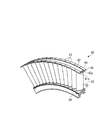
図2に示すように、静翼環32は、リング状の内側シュラウド35と外側シュラウド36との間に、多数の静翼37が放射状に取り付けられることで構成されている。これら多数の静翼37は、静翼環32の周方向に沿って等間隔に設置されている。この静翼環32は、内側シュラウド35、外側シュラウド36が周方向に複数(例えば8個)に分割された静翼環セグメント40によって構成されている。
The compressor 22 is an axial flow compressor in which the moving
The moving
As shown in FIG. 2, the
図3に示すように、各静翼環セグメント40は、複数(例えば10〜20個)のセグメント分割体41を、円弧状の結合部材(第二の部材)42によって結合することで形成されている。
各セグメント分割体41は、一枚の静翼43と、一枚の静翼43に対応するように内側シュラウド35、外側シュラウド36を分割してなる外側シュラウド部(第一の部材)44、内側シュラウド部45とから形成されている。これら静翼43、外側シュラウド部44、内側シュラウド部45は、所定の材料からなるブロック材から加工機械によって削り出すことで一体に形成されている。
As shown in FIG. 3, each stator
Each
図4に示すように、外側シュラウド部44は、所定の断面形状を有した帯状で、外側シュラウド36の曲率に応じた円弧状に湾曲形成されている。外側シュラウド部44の外周面(静翼43が設けられている側と反対側の面)には、その幅方向中央部に、外側シュラウド36の円周方向に連続する溝50が形成されている。この溝50に結合部材42が収容される。
帯状の外側シュラウド部44の幅方向両端部には、外側シュラウド36の円周方向に連続して突出する突条部46が形成されている。
As shown in FIG. 4, the
At both ends in the width direction of the belt-shaped
内側シュラウド部45は、所定の断面形状を有した帯状で、内側シュラウド35の曲率に応じた円弧状に湾曲形成されている。内側シュラウド部45の内周面(静翼43が設けられている側と反対側の面)には、その幅方向中央部に、内側シュラウド35の円周方向に連続する溝47が形成されている。
The
上記したようなセグメント分割体41は、結合部材42によって、一体化されて静翼環セグメント40を構成する。
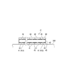
結合部材42は、静翼環セグメント40を構成する所定数のセグメント分割体41を結合するためのものであり、これら所定数のセグメント分割体41に応じた長さを有した帯状とされている。前述したように、結合部材42は、外側シュラウド部44の外周面に形成された溝50に収容される。そして、結合部材42の幅方向両側において、結合部材42と各セグメント分割体41とを溶接することで、所定数のセグメント分割体41が結合され、静翼環セグメント40が形成される。図5に示すように、結合部材42と各セグメント分割体41との溶接箇所48は、互いに隣接するセグメント分割体41、41を跨がないように設定される。これは、互いに隣接するセグメント分割体41、41を跨いで連続して溶接を行うと、熱影響の発生具合が互いに隣接するセグメント分割体41、41どうしで異なった場合に、静翼環セグメント40として変形や歪みが生じることがあるからである。
The
The
また、結合部材42は、所定数のセグメント分割体41を結合した状態で、結合部材42の端面42sが、静翼環セグメント40を構成する両端のセグメント分割体41の端面41aから突出せず、所定寸法(例えば2.5mm程度)内側に位置するように取り付けられる。これは、互いに隣接する静翼環セグメント40の結合部材42どうしが接触するのを防ぐためである。これにより、結合部材42の端面42sについては、鏡面仕上げ等とする必要がなく、加工の手間も省ける。
Further, the
ここで、外側シュラウド部44に形成された溝50と、結合部材42は、以下に示すような断面形状を有している。
すなわち、図6に示すように、溝50は、断面視したときに、底部50aが平面状で、溝50の幅が外周側から底部50aに向けて漸次小さくなるよう、幅方向両側の側壁部50bが底部50aに対して所定角度θ1傾斜して形成されている。ここで、前記の角度θ1は、30〜45°とするのが好ましく、より好ましくは33〜37°とするのが良い。本実施の形態では、例えばθ1=35°としている。
また、底部50aの幅方向両端部の、側壁部50bとの合わせ目の部分50cは、機械加工上の理由により0.4R程度のRが形成されている。
Here, the
That is, as shown in FIG. 6, the
Further, at the both end portions in the width direction of the
一方、結合部材42は、その幅が、厚さ方向中間部で最大になるような断面形状とされている。すなわち、結合部材42の幅方向両側の側面42aには、厚さ方向中間部に凸部42bが形成されている。この凸部42bは、例えば結合部材42の厚さを6mmとした場合、結合部材42を溝50に収容した状態で溝50の底部50aに対向する側の面から2mmの位置に形成されている。この凸部42bは、結合部材42を溝50に収容したときに、両側の凸部42bが溝50の側壁部50bに当接あるいは近接するように形成されている。そして、凸部42bの頂角の角度θ2は所定の角度と設定されている。本実施の形態では、例えばθ2=120°とされている。これにより、凸部42bの上方、下方において、側面42aはそれぞれ溝50の底部50aに直交する方向に対し、同一角度で傾斜し、本実施の形態の場合、30°傾斜して形成されている。
On the other hand, the
このような断面形状を有する結合部材42を溝50に収容すると、両側の凸部42bが溝50の側壁部50bに当接あるいは近接し、溝50の底部50a側には、結合部材42の側面42aと溝50の側壁部50bおよび底部50aに囲まれた空間100が形成され、溝50の底部50aから離れる側には断面略V字状の開先部200が形成される。
When the
結合部材42は、外側シュラウド部44の外周面に形成された溝50に収容され、結合部材42の幅方向両側の所定の溶接箇所48において、結合部材42と各セグメント分割体41とが溶接される。この溶接には、TIG溶接を用いることができる。溶接箇所48においては、断面略V字状の開先部200において溶接が行われる。このとき、開先部200の下方には、凸部42bの下方に空間100が形成されている。この空間100の存在により、溝50の底部50aの両端部の側壁部50bとの合わせ目の部分50cと、結合部材42の両端部との間にはクリアランスが形成される。前述したように、溝50の底部50aの両端部の側壁部50bとの合わせ目の部分50cには、機械加工上の理由により微小なRが存在するため、通常であれば結合部材42の両端部の角部と干渉して結合部材42と溝50の底部50aとを密着させるのが困難である。これに対し、上記構成により、溝50の底部50aに結合部材42を密着させてセットすることができる。
さらに、溶接時には、アシストガスが空間100に流れ込んで溝50の連続する方向に流れていくため、アシストガスによって溝50から結合部材42が浮き上がることもなく、開先部200の溶接を良好に行うことができる。
The
Further, during welding, the assist gas flows into the
このようにして、結合部材42を介して所定数のセグメント分割体41を結合することで構成された各静翼環セグメント40は、図4に示したように、その外周側において、ケーシング26によって、周方向に摺動可能に保持されている。このため、ケーシング26の内周面に、案内溝27が形成されている。この案内溝27は、前記の各セグメント分割体41の外側シュラウド部44に形成された突条部46に対応する断面形状を有しており、これにより複数のセグメント分割体41の集合体たる静翼環32は、外側シュラウド36がケーシング26に保持され、案内溝27が連続する方向、すなわち周方向に摺動可能に保持されている。
In this way, each stator
また、各静翼環セグメント40は、その内周側において、主軸(図示無し)に対し、シールホルダ49によってその径方向の位置が保持されている。シールホルダ49は、静翼環セグメント40に対応した長さを有している。シールホルダ49には、各セグメント分割体41の内側シュラウド部45に嵌合する嵌合部49aが形成されている。また、シールホルダ49の内周側には、シール部材49bが設けられ、主軸(図示無し)との間のシール性を確保するようになっている。
In addition, each stationary
上記のような各静翼環セグメント40は、ケーシング26に形成された案内溝27に順次挿入されてセットされることで、全体として円環状の静翼環32が構成される。
Each of the stator
さて、各静翼環セグメント40の組み立ては、以下のようにして行われる。
セグメント分割体41は、所定の材料からなるブロック材から削り出すことで形成される。また、結合部材42は、所定の材料からなる帯状の板材を、結合部材42の所定の断面形状に加工した後、所定の曲率半径を有する円弧状となるように、曲げ加工を行うことで形成される。
Now, the assembly of each stator
The segment divided
次いで、所定数のセグメント分割体41を結合部材42によって結合する。
これには、予め準備された所定数のセグメント分割体41を、溶接台上にセットする。本実施の形態においては、図5に示すように、これらセグメント分割体41を、溶接台300上に横置きにしてセットする(回転軸方向が溶接台300の上面に直交するように置く)。
複数のセグメント分割体41を、冶具によって互いに密着させた状態で、溶接台300)上で位置決めする。この状態で、複数のセグメント分割体41を点溶接で仮止めした後、溝50が加工され、溝50が連続した状態となる。
そして、溝50に結合部材42をセットする。
Next, a predetermined number of
For this, a predetermined number of
The plurality of
Then, the
続いて、結合部材42をセグメント分割体41に溶接していく。
このとき、溶接の順序は、図5に示したように、複数セットされたセグメント分割体41のうち、まず一方の端に位置するセグメント分割体41Aにおいて溶接を行い、次いで他方の端に位置するセグメント分割体41Bにおいて溶接を行い、この後は、これらセグメント分割体41の内側に配置されているものに向けて、両側を交互に溶接していくのが好ましい。
Subsequently, the
At this time, as shown in FIG. 5, among the plurality of
このようにして、セグメント分割体41を横置きにして溶接を行うことで、静翼43が荷重や熱応力によって歪むのを防ぐことができる。
In this way, by performing the welding with the segment divided
所定数のセグメント分割体41を結合部材42によって互いに結合して静翼環セグメント40を組み立てた後、その内周側にシールホルダ49を取り付ける。
上記と同様にして、静翼環32を構成するすべての静翼環セグメント40を組み立てた後、これら静翼環セグメント40を、ケーシング26に形成された案内溝27に順次挿入させてセットすることで、全体として円環状の静翼環32が構成される。
After assembling the stationary
In the same manner as described above, after assembling all the stator
上述したようにして、セグメント分割体41は、溶接箇所48において、外側シュラウド部44の周方向長さの一部に対してのみ、結合部材42との溶接が行われる。しかも、溶接深さは、開先部200の部分のみである。したがって、従来のように、電子ビーム溶接によって、周方向全域にわたって、静翼環の軸方向の中心部まで入熱する場合に比較すると、セグメント分割体41に対する入熱量は小さい。しかも、結合部材42との溶接は、各溶接箇所48においてセグメント分割体41一つずつに対して個別に行われ、不連続な溶接作業であるため、溶接に伴う熱を空気中に放散でき、熱が蓄積する恐れも少ない。
また、溶接箇所48は、外側シュラウド部44において静翼43が設けられている側と反対の側の面であるため、溶接による熱が静翼43に対して影響を及ぼすことも少ない。
このようにして、形成された静翼環セグメント40は、熱影響によって生じる変形や歪みを抑えることができる。その結果、外側シュラウド36への空気の出入りや静翼43の変形が抑制され、圧縮空気の流れが乱れるのを防ぐことができる。これにより、圧縮機22は所定の圧縮性能を保持することができ、ガスタービン20の熱効率を向上させることができる。
As described above, the segment divided
Further, since the welded
Thus, the formed stator
ここで、各セグメント分割体41に形成された溝50は、断面視したときに、溝50の幅が外周側から底部50aに向けて漸次小さくなるよう、両側の側壁部50bが底部50aに対して傾斜して形成され、結合部材42は、その幅が、厚さ方向中間部の凸部42bで最大になるような断面形状とされている。これにより、結合部材42を溝50に収容すると、両側の凸部42bが溝50の側壁部50bに当接あるいは近接し、溝50の底部50a側に空間100が形成され、溝50の底部50aから離れる側に断面略V字状の開先部200が形成されるようになっている。
このような結合部材42とセグメント分割体41とを溶接するときには、空間100により、溝50の底部50aの両端部の側壁部50bとの合わせ目の部分50cと、結合部材42の両端部との間にはクリアランスが形成されるので、溝50の底部50aに結合部材42を密着させてセットすることができる。さらに、溶接時には、フラックスやアシストガスが空間100に流れ込んで溝50の連続する方向に流れていくため、フラックスやアシストガスによって溝50から結合部材42が浮き上がることもなく、開先部200の溶接を良好に行うことができる。
このようにして、結合部材42を用いた静翼環セグメント40の組み立てを精度良く行うことが可能となり、これによっても、外側シュラウド36への空気の出入りや静翼43の変形が抑制され、圧縮空気の流れが乱れるのを防ぐことができる。その結果、圧縮機22は所定の圧縮性能を保持することができ、ガスタービン20の熱効率を向上させることができる。
Here, the
When welding such a
In this way, it is possible to assemble the stationary
なお、上記実施の形態では、ガスタービン20を構成する静翼環セグメント40において、複数のセグメント分割体41を結合部材42で結合するための溶接箇所48に本発明を適用する例を挙げたが、ガスタービン20の本願の主旨と関係しない他の部分の構成については適宜他の構成とすることができる。
また、溝や凹部に溶接対象物を収容して溶接を行うのであれば、溝50に結合部材42を収容して溶接する場合に限らず、例えば、円形、矩形等の凹部にプラグやプレートを溶接する場合など、他の対象物に対しても本発明を適用することで、溶接対象物の凹部からの浮き上がりを防いで良好な溶接が行えるといった上記と同様の効果を得ることが可能である。
これ以外にも、本発明の主旨を逸脱しない限り、上記実施の形態で挙げた構成を取捨選択したり、他の構成に適宜変更することが可能である。
In the above embodiment, the example in which the present invention is applied to the welded
In addition, if welding is performed with the welding object accommodated in the groove or the recess, the welding is not limited to the case where the
In addition to this, as long as it does not depart from the gist of the present invention, the configuration described in the above embodiment can be selected or changed to another configuration as appropriate.
20…ガスタービン、32…静翼環、35…内側シュラウド、36…外側シュラウド、37…静翼、40…静翼環セグメント、41…セグメント分割体、42…結合部材(第二の部材)、42a…側面、42b…凸部、43…静翼、44…外側シュラウド部(第一の部材)、45…内側シュラウド部、48…溶接箇所、50…溝、50a…底部、50b…側壁部、50c…部分、100…空間、200…開先部 20 ... gas turbine, 32 ... stationary blade ring, 35 ... inner shroud, 36 ... outer shroud, 37 ... stationary blade, 40 ... stationary blade ring segment, 41 ... segment segment, 42 ... coupling member (second member), 42a ... side face, 42b ... convex part, 43 ... stationary blade, 44 ... outer shroud part (first member), 45 ... inner shroud part, 48 ... welded place, 50 ... groove, 50a ... bottom part, 50b ... side wall part, 50c ... part, 100 ... space, 200 ... groove part
Claims (6)
前記内側シュラウドを周方向に分割してなる内側シュラウド部と前記外側シュラウドを周方向に分割してなる外側シュラウド部との間に1枚の前記静翼が設けられたセグメント分割体を複数並べて配置する工程と、
複数の前記セグメント分割体を、前記内側シュラウド部および前記外側シュラウド部の少なくとも一方において、帯状の結合部材によって互いに結合するため、前記内側シュラウド部および前記外側シュラウド部の少なくとも一方において、前記静翼が設けられた側とは反対側の面に形成された溝に前記結合部材を収容し、前記結合部材を前記溝の両側において前記内側シュラウド部および前記外側シュラウド部の少なくとも一方に溶接する工程と、を備え、
前記溝は、その幅が底部に向けて漸次小さくなるよう側壁部が傾斜して形成されるとともに、前記結合部材は、幅方向両側の側面に凸部が形成されて、
前記結合部材を前記溝に収容したときに、前記溝の側壁部と前記結合部材の前記側面との間に、前記凸部に対して前記底部側に空間が形成され、前記凸部に対して前記底部と反対側に断面略V字状の開先部が形成され、前記開先部において溶接を行うことを特徴とする静翼環セグメントの組立方法。 A method of assembling a stator blade ring segment that constitutes a stator blade ring in which a plurality of stator blades are provided between an annular inner shroud and an outer shroud by combining a plurality of the blades,
A plurality of segmented segments provided with one stationary blade are arranged between an inner shroud portion obtained by dividing the inner shroud in the circumferential direction and an outer shroud portion obtained by dividing the outer shroud in the circumferential direction. And a process of
In order to couple a plurality of the segment division bodies to each other by a band-shaped coupling member in at least one of the inner shroud portion and the outer shroud portion, the stationary blade is disposed in at least one of the inner shroud portion and the outer shroud portion. Receiving the coupling member in a groove formed on a surface opposite to the provided side, and welding the coupling member to at least one of the inner shroud portion and the outer shroud portion on both sides of the groove; With
The groove is formed such that the side wall portion is inclined so that its width gradually decreases toward the bottom portion, and the coupling member has convex portions formed on the side surfaces on both sides in the width direction,
When the coupling member is accommodated in the groove, a space is formed on the bottom side with respect to the convex portion between the side wall portion of the groove and the side surface of the coupling member. A method of assembling a stator blade ring segment, wherein a groove portion having a substantially V-shaped cross section is formed on the side opposite to the bottom portion, and welding is performed at the groove portion.
並べて配置されることで連続した複数の前記セグメント分割体の前記溝に前記結合部材を収容することを特徴とする請求項1に記載の静翼環セグメントの組立方法。 In the step of coupling the plurality of segment pieces together by the coupling member, a predetermined number of the segment pieces are arranged side by side so that the axial direction of each of the segment pieces is a substantially vertical direction,
The method of assembling a stator blade ring segment according to claim 1, wherein the coupling member is accommodated in the groove of the plurality of segment divisions that are arranged side by side.
前記内側シュラウドを周方向に分割してなる内側シュラウド部と前記外側シュラウドを周方向に分割してなる外側シュラウド部との間に1枚の前記静翼が設けられたセグメント分割体が複数並べて配置され、これら複数の前記セグメント分割体が、前記内側シュラウド部および前記外側シュラウド部の少なくとも一方において、前記静翼が設けられた側と反対側に形成された溝に収容された帯状の結合部材が溶接されることによって互いに結合され、
前記結合部材は、厚さ方向中間部において幅が最大となるよう、幅方向両側の側面に凸部が形成され、
前記溝は、その幅が底部に向けて漸次小さくなるよう側壁部が傾斜して形成されて、
前記結合部材が前記溝に収容された状態で、前記溝の側壁部と前記結合部材の前記側面との間に、前記凸部に対して前記底部側に空間が形成されるとともに、前記凸部に対して前記底部と反対側に断面略V字状の開先部が形成され、前記開先部において前記内側シュラウド部および前記外側シュラウド部の少なくとも一方と前記結合部材とが溶接されていることを特徴とする静翼環セグメント。 By combining a plurality, a stator blade ring segment constituting a stator blade ring in which a plurality of stator blades are provided between an annular inner shroud and an outer shroud,
A plurality of segment division bodies in which one stationary blade is provided are arranged between an inner shroud portion obtained by dividing the inner shroud in the circumferential direction and an outer shroud portion obtained by dividing the outer shroud in the circumferential direction. A plurality of the segment divided bodies are band-shaped coupling members housed in grooves formed on the side opposite to the side where the stationary blades are provided in at least one of the inner shroud portion and the outer shroud portion. Joined together by welding
The coupling member is formed with convex portions on the side surfaces on both sides in the width direction so that the width is maximum in the middle portion in the thickness direction,
The groove is formed such that the side wall is inclined so that its width gradually decreases toward the bottom,
In a state where the coupling member is accommodated in the groove, a space is formed on the bottom side with respect to the convex portion between the side wall portion of the groove and the side surface of the coupling member, and the convex portion A groove portion having a substantially V-shaped cross section is formed on the opposite side to the bottom portion, and at least one of the inner shroud portion and the outer shroud portion and the coupling member are welded to the groove portion. Stator blade segment characterized by.
前記結合部材は、帯状で、厚さ方向中間部において幅が最大となるよう、幅方向両側の側面に凸部が形成され、
前記セグメント分割体の前記内側シュラウド部および前記外側シュラウド部の少なくとも一方に形成された溝に収容されたときに、前記溝の側壁部と前記結合部材の前記側面との間に、前記凸部に対して前記溝の底部側に空間が形成されるとともに、前記凸部に対して前記底部と反対側に断面略V字状の開先部が形成されることを特徴とする結合部材。 By combining a plurality, the inner shroud is divided in the circumferential direction to form a stator blade ring segment that forms a stator blade ring in which a plurality of stator blades are provided between an annular inner shroud and an outer shroud. A connecting member for connecting a plurality of segmented segments each provided with one stationary blade between an inner shroud portion and an outer shroud portion obtained by dividing the outer shroud in the circumferential direction. And
The coupling member has a band shape, and convex portions are formed on the side surfaces on both sides in the width direction so that the width is maximum in the middle portion in the thickness direction.
When the projection is accommodated in a groove formed in at least one of the inner shroud portion and the outer shroud portion of the segment divided body, the convex portion is provided between the side wall portion of the groove and the side surface of the coupling member. On the other hand, a space is formed on the bottom side of the groove, and a groove portion having a substantially V-shaped cross section is formed on the opposite side to the bottom with respect to the convex portion.
前記溝または前記凹部は、その開口幅が底部に向けて漸次小さくなるよう側壁部が傾斜して形成されるとともに、前記第二の部材は、厚さ方向中間部において幅が最大となるよう外周部の側面に凸部が形成され、
前記第二の部材を前記溝または前記凹部に収容したときに、前記側壁部と前記第二の部材の外周部との間に、前記凸部に対して前記底部側に空間が形成され、前記凸部に対して前記底部と反対側に断面略V字状の開先部が形成されるようにし、
前記第二の部材の外周部の少なくとも一部において前記開先部を溶接することで、前記第一の部材と前記第二の部材とを溶接することを特徴とする溶接方法。 A method of welding a first member in which a groove or a recess is formed and a second member accommodated in the groove or the recess in at least a part of an outer peripheral portion of the second member,
The groove or the recess is formed with an inclined side wall so that the opening width gradually decreases toward the bottom, and the second member has an outer periphery so that the width is maximized in the middle portion in the thickness direction. Convex is formed on the side of the part,
When the second member is accommodated in the groove or the concave portion, a space is formed on the bottom side with respect to the convex portion between the side wall portion and the outer peripheral portion of the second member, A groove portion having a substantially V-shaped cross section is formed on the side opposite to the bottom portion with respect to the convex portion,
Welding method characterized by welding said 1st member and said 2nd member by welding said groove part in at least one part of the perimeter part of said 2nd member.
Priority Applications (6)
| Application Number | Priority Date | Filing Date | Title |
|---|---|---|---|
| JP2007267667A JP5091615B2 (en) | 2007-10-15 | 2007-10-15 | Stator blade ring segment assembly method, stator blade ring segment, connecting member, welding method |
| PCT/JP2008/068535 WO2009051089A1 (en) | 2007-10-15 | 2008-10-14 | Assembling method of stator blade ring segment, stator blade ring segment, coupling member, welding method |
| US12/449,828 US8215904B2 (en) | 2007-10-15 | 2008-10-14 | Assembling method of stator blade ring segment, stator blade ring segment, coupling member, welding method |
| EP08839009.1A EP2187062B1 (en) | 2007-10-15 | 2008-10-14 | Assembling method of a stator blade ring segment, and stator blade ring segment |
| CN2008800056870A CN101617129B (en) | 2007-10-15 | 2008-10-14 | Assembling method of stator blade ring segment, stator blade ring segment, coupling member, welding method |
| KR1020097017419A KR101183791B1 (en) | 2007-10-15 | 2008-10-14 | Assembling method of stator blade ring segment, stator blade ring segment, coupling member, welding method |
Applications Claiming Priority (1)
| Application Number | Priority Date | Filing Date | Title |
|---|---|---|---|
| JP2007267667A JP5091615B2 (en) | 2007-10-15 | 2007-10-15 | Stator blade ring segment assembly method, stator blade ring segment, connecting member, welding method |
Publications (2)
| Publication Number | Publication Date |
|---|---|
| JP2009097370A true JP2009097370A (en) | 2009-05-07 |
| JP5091615B2 JP5091615B2 (en) | 2012-12-05 |
Family
ID=40567353
Family Applications (1)
| Application Number | Title | Priority Date | Filing Date |
|---|---|---|---|
| JP2007267667A Active JP5091615B2 (en) | 2007-10-15 | 2007-10-15 | Stator blade ring segment assembly method, stator blade ring segment, connecting member, welding method |
Country Status (6)
| Country | Link |
|---|---|
| US (1) | US8215904B2 (en) |
| EP (1) | EP2187062B1 (en) |
| JP (1) | JP5091615B2 (en) |
| KR (1) | KR101183791B1 (en) |
| CN (1) | CN101617129B (en) |
| WO (1) | WO2009051089A1 (en) |
Cited By (4)
| Publication number | Priority date | Publication date | Assignee | Title |
|---|---|---|---|---|
| WO2013146590A1 (en) * | 2012-03-30 | 2013-10-03 | 三菱重工業株式会社 | Stator blade segment and axial flow fluid machine with same |
| WO2015056513A1 (en) * | 2013-10-15 | 2015-04-23 | 株式会社Ihi | Method for bonding metal powder injection molded bodies |
| US9086078B2 (en) | 2011-02-28 | 2015-07-21 | Mitsubishi Hitachi Power Systems, Ltd. | Stationary vane unit of rotary machine, method of producing the same, and method of connecting the same |
| JP2016540917A (en) * | 2013-10-25 | 2016-12-28 | シーメンス アクチエンゲゼルシヤフトSiemens Aktiengesellschaft | Outer vane support ring with a rigid back plate in the compressor section of a gas turbine engine |
Families Citing this family (8)
| Publication number | Priority date | Publication date | Assignee | Title |
|---|---|---|---|---|
| CN101652534B (en) * | 2007-06-22 | 2012-07-04 | 三菱重工业株式会社 | Stator blade ring and axial flow compressor using the same |
| EP2770166B1 (en) | 2013-02-20 | 2017-04-12 | General Electric Technology GmbH | Damper for compressor blade feet |
| US8939717B1 (en) * | 2013-10-25 | 2015-01-27 | Siemens Aktiengesellschaft | Vane outer support ring with no forward hook in a compressor section of a gas turbine engine |
| CN104314620A (en) * | 2014-10-28 | 2015-01-28 | 东方电气集团东方汽轮机有限公司 | Fixed blading structure for turbine |
| CN111315963B (en) * | 2017-09-20 | 2023-03-24 | 苏舍涡轮服务芬洛有限公司 | Assembly of blade units |
| CN114211199B (en) * | 2022-01-04 | 2023-10-27 | 重庆江增船舶重工有限公司 | Combined machining method for two-half thin-wall part (stationary blade) |
| CN115319456B (en) * | 2022-07-06 | 2023-12-05 | 中国船舶重工集团公司第七0三研究所 | Assembling method for cylindrical gas turbine compressor casing |
| KR102578467B1 (en) * | 2023-02-22 | 2023-09-14 | 주식회사 근옥 | Prefabricated swirl plate |
Citations (6)
| Publication number | Priority date | Publication date | Assignee | Title |
|---|---|---|---|---|
| JPH02245403A (en) * | 1989-02-21 | 1990-10-01 | Westinghouse Electric Corp <We> | Compressor diaphragm assembly for combustion turbine and assembly method thereof |
| JPH0399780A (en) * | 1989-09-11 | 1991-04-24 | Ford Motor Co | Method of gas metal arc welding of aluminum base work |
| JPH06320277A (en) * | 1993-04-28 | 1994-11-22 | Shimakura Tekkosho:Kk | Welding method for high purity ferritic stainless steel |
| JP2002162391A (en) * | 2000-11-27 | 2002-06-07 | Ishikawajima Harima Heavy Ind Co Ltd | Method and device for inspecting canister lid welded part |
| JP2002242611A (en) * | 2001-02-19 | 2002-08-28 | Mitsubishi Heavy Ind Ltd | Stator vane assembly, and fluid operated rotary machine with the stator vane assembly |
| JP2003164983A (en) * | 2001-11-28 | 2003-06-10 | Toshiba Corp | Welding method for metallic member |
Family Cites Families (13)
| Publication number | Priority date | Publication date | Assignee | Title |
|---|---|---|---|---|
| FR975095A (en) * | 1942-01-29 | 1951-03-01 | & Chantiers De Bretagne Atel | Fixed fin design for steam or gas turbines and rotary compressors |
| US2497041A (en) * | 1945-03-27 | 1950-02-07 | United Aircraft Corp | Nozzle ring for gas turbines |
| US3860785A (en) * | 1974-02-01 | 1975-01-14 | Crc Crose Int Inc | Grounding device for electric welding |
| JPS592761B2 (en) | 1975-11-14 | 1984-01-20 | 株式会社日立製作所 | Nozzle details |
| JPS5857276B2 (en) | 1979-06-20 | 1983-12-19 | 株式会社日立製作所 | Electron beam welding method for dissimilar metals |
| JPS5857276A (en) | 1981-09-30 | 1983-04-05 | 日東電工株式会社 | Terminal board |
| SE455219B (en) | 1982-01-20 | 1988-06-27 | Westinghouse Electric Corp | COMPRESSOR GLASS CRANE IN A COMBUSTION TURBINE |
| JPS592761A (en) | 1982-06-26 | 1984-01-09 | 共成産業株式会社 | Instantaneous valve opening apparatus for supplying fluid |
| IT1234489B (en) * | 1989-02-06 | 1992-05-18 | Chimento Adriano S P A | METHOD OF COMPOSITION OF MANUFACTURES SUITABLE FOR MAKING NECKLACES, BRACELETS OR SIMILAR OBJECTS AND OBJECTS MADE WITH THE SAID METHOD |
| FR2647502B1 (en) * | 1989-05-23 | 1991-09-13 | Europ Propulsion | TURBINE DISTRIBUTOR FOR TURBO-REACTOR AND MANUFACTURING METHOD THEREOF |
| US6893214B2 (en) * | 2002-12-20 | 2005-05-17 | General Electric Company | Shroud segment and assembly with surface recessed seal bridging adjacent members |
| US20070122274A1 (en) * | 2005-11-29 | 2007-05-31 | General Electric Company | Tip shroud attachment for stator vane |
| CN101652534B (en) * | 2007-06-22 | 2012-07-04 | 三菱重工业株式会社 | Stator blade ring and axial flow compressor using the same |
-
2007
- 2007-10-15 JP JP2007267667A patent/JP5091615B2/en active Active
-
2008
- 2008-10-14 EP EP08839009.1A patent/EP2187062B1/en active Active
- 2008-10-14 KR KR1020097017419A patent/KR101183791B1/en active IP Right Grant
- 2008-10-14 CN CN2008800056870A patent/CN101617129B/en active Active
- 2008-10-14 US US12/449,828 patent/US8215904B2/en active Active
- 2008-10-14 WO PCT/JP2008/068535 patent/WO2009051089A1/en active Application Filing
Patent Citations (6)
| Publication number | Priority date | Publication date | Assignee | Title |
|---|---|---|---|---|
| JPH02245403A (en) * | 1989-02-21 | 1990-10-01 | Westinghouse Electric Corp <We> | Compressor diaphragm assembly for combustion turbine and assembly method thereof |
| JPH0399780A (en) * | 1989-09-11 | 1991-04-24 | Ford Motor Co | Method of gas metal arc welding of aluminum base work |
| JPH06320277A (en) * | 1993-04-28 | 1994-11-22 | Shimakura Tekkosho:Kk | Welding method for high purity ferritic stainless steel |
| JP2002162391A (en) * | 2000-11-27 | 2002-06-07 | Ishikawajima Harima Heavy Ind Co Ltd | Method and device for inspecting canister lid welded part |
| JP2002242611A (en) * | 2001-02-19 | 2002-08-28 | Mitsubishi Heavy Ind Ltd | Stator vane assembly, and fluid operated rotary machine with the stator vane assembly |
| JP2003164983A (en) * | 2001-11-28 | 2003-06-10 | Toshiba Corp | Welding method for metallic member |
Cited By (9)
| Publication number | Priority date | Publication date | Assignee | Title |
|---|---|---|---|---|
| US9086078B2 (en) | 2011-02-28 | 2015-07-21 | Mitsubishi Hitachi Power Systems, Ltd. | Stationary vane unit of rotary machine, method of producing the same, and method of connecting the same |
| WO2013146590A1 (en) * | 2012-03-30 | 2013-10-03 | 三菱重工業株式会社 | Stator blade segment and axial flow fluid machine with same |
| JP2013209896A (en) * | 2012-03-30 | 2013-10-10 | Mitsubishi Heavy Ind Ltd | Stator blade segment and axial flow fluid machine with the same |
| KR20140129257A (en) | 2012-03-30 | 2014-11-06 | 미츠비시 쥬고교 가부시키가이샤 | Stator blade segment and axial flow fluid machine with same |
| US9523286B2 (en) | 2012-03-30 | 2016-12-20 | Mitsubishi Heavy Industries, Ltd. | Vane segment and axial-flow fluid machine including the same |
| DE112013001838B4 (en) | 2012-03-30 | 2018-06-14 | Mitsubishi Heavy Industries, Ltd. | Guide vane segment and this containing Axialströmungsfluidmaschine |
| WO2015056513A1 (en) * | 2013-10-15 | 2015-04-23 | 株式会社Ihi | Method for bonding metal powder injection molded bodies |
| JPWO2015056513A1 (en) * | 2013-10-15 | 2017-03-09 | 株式会社Ihi | Joining method of metal powder injection molding |
| JP2016540917A (en) * | 2013-10-25 | 2016-12-28 | シーメンス アクチエンゲゼルシヤフトSiemens Aktiengesellschaft | Outer vane support ring with a rigid back plate in the compressor section of a gas turbine engine |
Also Published As
| Publication number | Publication date |
|---|---|
| EP2187062A1 (en) | 2010-05-19 |
| KR101183791B1 (en) | 2012-09-17 |
| EP2187062A4 (en) | 2014-12-31 |
| EP2187062B1 (en) | 2016-03-16 |
| US8215904B2 (en) | 2012-07-10 |
| WO2009051089A1 (en) | 2009-04-23 |
| CN101617129A (en) | 2009-12-30 |
| KR20090104112A (en) | 2009-10-05 |
| CN101617129B (en) | 2011-11-09 |
| JP5091615B2 (en) | 2012-12-05 |
| US20100135782A1 (en) | 2010-06-03 |
Similar Documents
| Publication | Publication Date | Title |
|---|---|---|
| JP5091615B2 (en) | Stator blade ring segment assembly method, stator blade ring segment, connecting member, welding method | |
| US8459944B2 (en) | Stator blade ring and axial flow compressor using the same | |
| JP4918263B2 (en) | Stator blade ring of axial compressor | |
| EP1479952B1 (en) | Shaft seal mechanism | |
| CN102132011B (en) | Fixed vane assembly for turbine engine with reduced weight, and a turbine engine including at least one such fixed vane assembly | |
| US7618234B2 (en) | Hook ring segment for a compressor vane | |
| JP5634715B2 (en) | Method for manufacturing compliant plate seal assembly | |
| WO2009157817A1 (en) | Vane assembly and method of fabricating, and a turbo-machine with such vane assembly | |
| JP2006052765A (en) | Shaft sealing mechanism, structure for mounting this mechanism on stator, and turbine with the same structure | |
| US9869194B2 (en) | Seal assembly to seal corner leaks in gas turbine | |
| WO2013146590A1 (en) | Stator blade segment and axial flow fluid machine with same | |
| US10655489B2 (en) | Systems and methods for assembling flow path components | |
| US9822669B2 (en) | Turbine assembly with detachable struts | |
| RU2631585C2 (en) | Compressor stator for turbomachine | |
| US20130181412A1 (en) | Shaft sealing apparatus and rotating machine equipped therewith | |
| RU2531094C2 (en) | Transition duct of gas turbine engine and method of its manufacturing, and also gas turbine engine | |
| JP4436273B2 (en) | Turbine partition plate and turbine provided with the same | |
| JP2009002338A (en) | Stationary blade ring, axial flow compressor using the same, and method for repairing stationary blade ring | |
| JP2004197622A (en) | Turbine compressor stationary blade | |
| US10689994B2 (en) | Seal assembly to seal corner leaks in gas turbine | |
| EP3805526A1 (en) | Seal assembly for chute gap leakage reduction in a gas turbine | |
| JP2005113881A (en) | Seal structure for turbine, seal stator and turbine nozzle segment | |
| EA044753B1 (en) | COMPOSITE SEALING STRUCTURE FOR MACHINE AND METHOD FOR MANUFACTURING COMPOSITE SEALING STRUCTURE |
Legal Events
| Date | Code | Title | Description |
|---|---|---|---|
| A621 | Written request for application examination |
Free format text: JAPANESE INTERMEDIATE CODE: A621 Effective date: 20100803 |
|
| TRDD | Decision of grant or rejection written | ||
| A01 | Written decision to grant a patent or to grant a registration (utility model) |
Free format text: JAPANESE INTERMEDIATE CODE: A01 Effective date: 20120821 |
|
| A01 | Written decision to grant a patent or to grant a registration (utility model) |
Free format text: JAPANESE INTERMEDIATE CODE: A01 |
|
| A61 | First payment of annual fees (during grant procedure) |
Free format text: JAPANESE INTERMEDIATE CODE: A61 Effective date: 20120914 |
|
| FPAY | Renewal fee payment (event date is renewal date of database) |
Free format text: PAYMENT UNTIL: 20150921 Year of fee payment: 3 |
|
| R151 | Written notification of patent or utility model registration |
Ref document number: 5091615 Country of ref document: JP Free format text: JAPANESE INTERMEDIATE CODE: R151 |
|
| FPAY | Renewal fee payment (event date is renewal date of database) |
Free format text: PAYMENT UNTIL: 20150921 Year of fee payment: 3 |
|
| S111 | Request for change of ownership or part of ownership |
Free format text: JAPANESE INTERMEDIATE CODE: R313111 |
|
| R350 | Written notification of registration of transfer |
Free format text: JAPANESE INTERMEDIATE CODE: R350 |
|
| R250 | Receipt of annual fees |
Free format text: JAPANESE INTERMEDIATE CODE: R250 |
|
| S533 | Written request for registration of change of name |
Free format text: JAPANESE INTERMEDIATE CODE: R313533 |
|
| R350 | Written notification of registration of transfer |
Free format text: JAPANESE INTERMEDIATE CODE: R350 |