JP2009096236A - Braking device and braking control device - Google Patents
Braking device and braking control device Download PDFInfo
- Publication number
- JP2009096236A JP2009096236A JP2007267164A JP2007267164A JP2009096236A JP 2009096236 A JP2009096236 A JP 2009096236A JP 2007267164 A JP2007267164 A JP 2007267164A JP 2007267164 A JP2007267164 A JP 2007267164A JP 2009096236 A JP2009096236 A JP 2009096236A
- Authority
- JP
- Japan
- Prior art keywords
- brake
- braking
- brake fluid
- electric motor
- fluid pressurizing
- Prior art date
- Legal status (The legal status is an assumption and is not a legal conclusion. Google has not performed a legal analysis and makes no representation as to the accuracy of the status listed.)
- Pending
Links
Images


Landscapes
- Valves And Accessory Devices For Braking Systems (AREA)
- Regulating Braking Force (AREA)
Abstract
Description
本発明は、車両に搭載される制動装置に対する操作を検出することに関する。 The present invention relates to detecting an operation on a braking device mounted on a vehicle.
乗用車やバス、トラック等の車両には、制動装置が設けられている。近年においては、加圧源と液圧制御部とにより、それぞれの車輪に設けられる制動力発生手段への液圧を調整して、それぞれの車輪の制動力を調整できる電子制御式の制動装置が普及してきている。例えば、特許文献1には、ブレーキペダルの操作状態を検出するペダル操作状態検出手段と、液圧発生源から供給される制動装置の作動液の圧力を検出する圧力検出手段とを備え、ペダル操作状態検出手段の出力値の時間変化率と、圧力検出手段の出力値の時間変化率との比に基づいて、両者のうち少なくとも一方に異常が発生していることを判定する車両制動装置が開示されている。 Vehicles such as passenger cars, buses, and trucks are provided with braking devices. In recent years, an electronically controlled braking device that can adjust the braking force of each wheel by adjusting the hydraulic pressure to the braking force generating means provided on each wheel by a pressurizing source and a hydraulic pressure control unit. It has become widespread. For example, Patent Literature 1 includes a pedal operation state detection unit that detects an operation state of a brake pedal, and a pressure detection unit that detects a pressure of hydraulic fluid of a brake device supplied from a hydraulic pressure generation source. Disclosed is a vehicle braking device that determines that an abnormality has occurred in at least one of the two based on the ratio of the time change rate of the output value of the state detection means and the time change rate of the output value of the pressure detection means. Has been.
特許文献1に開示された技術では、複数のセンサ、すなわちペダル操作状態検出手段及び圧力検出手段を用いて運転者の制動要求であるブレーキの操作を検出する。このように、ブレーキの操作を検出する際に複数のセンサ類を用いると、一つのセンサ類に異常が発生した場合でも、正常なセンサ類によって制御を継続できるので信頼性が向上する。しかし、センサ類の数が増加してしまい、製造コストの増加を招くおそれがある。 In the technique disclosed in Patent Literature 1, a brake operation, which is a driver's braking request, is detected using a plurality of sensors, that is, a pedal operation state detection unit and a pressure detection unit. As described above, when a plurality of sensors are used when detecting the operation of the brake, even if an abnormality occurs in one sensor, the control can be continued with the normal sensors, so that the reliability is improved. However, the number of sensors increases, which may increase the manufacturing cost.
そこで、この発明は、上記に鑑みてなされたものであって、新たなブレーキ操作検出手段を追加せずに、ブレーキの操作を検出するブレーキ操作検出手段に異常があった場合でもブレーキの操作を検出できる制動装置及び制動制御装置を提供することを目的とする。 Therefore, the present invention has been made in view of the above, and without adding a new brake operation detecting means, even when there is an abnormality in the brake operation detecting means for detecting the brake operation, the brake operation can be performed. It is an object of the present invention to provide a braking device and a braking control device that can be detected.
上述した課題を解決し、目的を達成するために、本発明に係る制動装置は、車両が備える車輪に制動力を発生させる制動力発生手段へ、ブレーキ液を介して前記制動力を発生させるための力を伝達する制動装置であり、ブレーキの操作状態を検出する少なくとも一つのブレーキ操作検出手段と、前記制動力発生手段へ前記ブレーキ液の圧力を伝達する圧力伝達系統に接続され、前記圧力伝達系統の前記ブレーキ液に圧力を発生させるブレーキ液加圧手段と、少なくとも一つの前記ブレーキ操作検出手段に異常があった場合には、前記ブレーキ液加圧手段を常時駆動するとともに、前記ブレーキ液加圧手段を駆動する負荷に関するパラメータに基づいて、前記ブレーキの操作状態を検出するブレーキ操作補助検出手段と、を含むことを特徴とする。 In order to solve the above-described problems and achieve the object, a braking device according to the present invention generates braking force via braking fluid to braking force generation means that generates braking force on wheels provided in the vehicle. A braking device that transmits the force of the brake, and is connected to at least one brake operation detecting means for detecting an operation state of the brake, and a pressure transmission system for transmitting the pressure of the brake fluid to the braking force generating means, and the pressure transmission When there is an abnormality in the brake fluid pressurizing means for generating pressure in the brake fluid of the system and at least one of the brake operation detecting means, the brake fluid pressurizing means is always driven and the brake fluid pressurizing means is operated. Brake operation assistance detecting means for detecting an operation state of the brake based on a parameter relating to a load for driving the pressure means. .
本発明の望ましい態様としては、前記制動装置において、前記ブレーキ液加圧手段は、電動機により駆動されるポンプであり、また、前記ブレーキ液加圧手段の負荷に関するパラメータは、前記電動機の駆動電流値であり、前記ブレーキ操作補助検出手段は、前記駆動電流値が予め定めた駆動電流閾値よりも大きい場合には、前記ブレーキの操作が発生したと判定することが好ましい。 As a desirable mode of the present invention, in the braking device, the brake fluid pressurizing means is a pump driven by an electric motor, and a parameter relating to a load of the brake fluid pressurizing means is a drive current value of the electric motor. Preferably, the brake operation auxiliary detection means determines that the brake operation has occurred when the drive current value is larger than a predetermined drive current threshold.
本発明の望ましい態様としては、前記制動装置において、前記ブレーキ液加圧手段は、電動機により駆動されるポンプであり、また、前記ブレーキ液加圧手段の負荷に関するパラメータは、前記電動機の回転数であり、前記ブレーキ操作補助検出手段は、前記回転数が予め定めた回転数閾値よりも小さい場合には、前記ブレーキの操作が発生したと判定することが好ましい。 As a desirable mode of the present invention, in the braking device, the brake fluid pressurizing means is a pump driven by an electric motor, and a parameter relating to a load of the brake fluid pressurizing means is a rotational speed of the electric motor. In addition, it is preferable that the brake operation auxiliary detection unit determines that the operation of the brake has occurred when the rotation speed is smaller than a predetermined rotation speed threshold value.
上述した課題を解決し、目的を達成するために、本発明に係る制動制御装置は、車両が備える車輪に制動力を発生させる制動力発生手段へ、ブレーキ液を介して前記制動力を発生させるための力を伝達し、ブレーキの操作状態を検出する少なくとも一つのブレーキ操作検出手段と、前記制動力発生手段へ前記ブレーキ液の圧力を伝達する圧力伝達系統に接続され、前記圧力伝達系統の前記ブレーキ液に圧力を発生させるブレーキ液加圧手段と、を含む制動装置のブレーキの操作状態を検出するものであり、前記ブレーキ操作検出手段の異常の有無を判定する異常判定部と、前記異常判定部が、前記ブレーキ操作検出手段に異常があったと判定した場合には、前記ブレーキ液加圧手段を常時駆動するブレーキ液加圧手段制御部と、前記ブレーキ液加圧手段を駆動する負荷に関するパラメータに基づいて前記ブレーキの操作状態を判定するブレーキ操作判定部と、を含むことを特徴とする。 In order to solve the above-described problems and achieve the object, a braking control device according to the present invention generates the braking force via a brake fluid to a braking force generation unit that generates a braking force on a wheel of the vehicle. And at least one brake operation detecting means for detecting a brake operation state, and a pressure transmission system for transmitting the pressure of the brake fluid to the braking force generation means, A brake fluid pressurizing unit that generates pressure in the brake fluid, and detecting an operation state of a brake of a braking device, an abnormality determination unit that determines whether the brake operation detection unit is abnormal, and the abnormality determination A brake fluid pressurizing means control unit that constantly drives the brake fluid pressurizing means, and the brake when the brake operation detecting means determines that there is an abnormality. Characterized in that it comprises a and a brake operation determining unit determines an operation state of the brake on the basis of parameters related to the load to drive the pressurizing means.
本発明の望ましい態様としては、前記制動制御装置において、前記ブレーキ液加圧手段は、電動機により駆動されるポンプであって、前記ブレーキ液加圧手段の負荷に関するパラメータは、前記電動機の駆動電流値であり、前記ブレーキ操作判定部は、前記駆動電流値が予め定めた駆動電流閾値よりも大きい場合には、前記ブレーキの操作が発生したと判定することが好ましい。 As a desirable mode of the present invention, in the braking control device, the brake fluid pressurizing means is a pump driven by an electric motor, and a parameter relating to a load of the brake fluid pressurizing means is a drive current value of the electric motor. The brake operation determination unit preferably determines that the brake operation has occurred when the drive current value is larger than a predetermined drive current threshold.
本発明の望ましい態様としては、前記制動制御装置において、前記ブレーキ液加圧手段は、電動機により駆動されるポンプであって、前記ブレーキ液加圧手段の負荷に関するパラメータは、前記電動機の回転数であり、前記ブレーキ操作判定部は、前記回転数が予め定めた回転数閾値よりも小さい場合には、前記ブレーキの操作が発生したと判定することが好ましい。 As a desirable mode of the present invention, in the braking control device, the brake fluid pressurizing means is a pump driven by an electric motor, and a parameter relating to a load of the brake fluid pressurizing means is a rotational speed of the electric motor. In addition, it is preferable that the brake operation determination unit determines that the operation of the brake has occurred when the rotation speed is smaller than a predetermined rotation speed threshold.
本発明は、新たなブレーキ操作検出手段を追加せずに、ブレーキの操作を検出するブレーキ操作検出手段に異常があった場合でもブレーキの操作を検出できる。 The present invention can detect the brake operation even when there is an abnormality in the brake operation detection means for detecting the brake operation without adding a new brake operation detection means.
以下、この発明につき図面を参照しつつ詳細に説明する。なお、この発明を実施するための最良の形態(以下実施形態という)によりこの発明が限定されるものではない。また、下記実施の形態における構成要素には、当業者が容易に想定できるもの、実質的に同一のもの、いわゆる均等の範囲のものが含まれる。なお、本発明は、ブレーキ液を介して踏力を各車輪に設けられる制動力発生手段へ伝達する制動装置を備える車両に対して適用でき、その車両の動力発生源や動力伝達方式は問わない。 Hereinafter, the present invention will be described in detail with reference to the drawings. The present invention is not limited by the best mode for carrying out the invention (hereinafter referred to as an embodiment). In addition, constituent elements in the following embodiments include those that can be easily assumed by those skilled in the art, those that are substantially the same, and those in a so-called equivalent range. The present invention can be applied to a vehicle including a braking device that transmits a pedaling force to braking force generating means provided on each wheel via brake fluid, and the power generation source and power transmission system of the vehicle are not limited.
本実施形態は、車両が備える車輪に制動力を発生させる制動力発生手段へ、ブレーキ液を介して前記制動力を発生させるための力を伝達するとともに、ブレーキ操作の有無や踏力等といったブレーキの操作状態を検出する少なくとも一つのブレーキ操作検出手段を備える制動装置であり、少なくとも一つのブレーキ操作検出手段に異常があった場合には、制動力発生手段のブレーキ液の圧力を増加させるブレーキ液加圧手段を常時駆動するとともに、ブレーキ液加圧手段を駆動する負荷に関するパラメータに基づいて、ブレーキの操作状態を判定する点に特徴がある。 In the present embodiment, a force for generating the braking force is transmitted via a brake fluid to a braking force generating means for generating a braking force on a wheel provided in the vehicle, and a brake operation such as presence / absence of a brake operation, a pedaling force, and the like is transmitted. A braking device comprising at least one brake operation detecting means for detecting an operation state, and when there is an abnormality in at least one brake operation detecting means, brake fluid application for increasing the brake fluid pressure of the braking force generating means. It is characterized in that the operating state of the brake is determined based on the parameter relating to the load for driving the brake fluid pressurizing means while always driving the pressure means.
図1は、本実施形態に係る制動装置及び制動制御装置が適用される車両を示す模式図である。車両100は、車輪10FL、10FR、10RL、10RRを備える。また、車両100は、車輪10FL、10FR、10RL、10RRに制動力(機械的な制動力であり、車輪制動力という)を発生させる制動装置101を備える。制動装置101は、ブレーキ液の圧力により、それぞれの車輪10FL、10FR、10RL、10RRに機械的な車輪制動トルクを付与し、それぞれの車輪10FL、10FR、10RL、10RRに車輪制動力を発生させることにより、車両100を制動する力(車両制動力)を発生させる。ここで、FLは車両100の左前を表し、FRは車両100の右前を表し、RLは車両100の左後を表し、RRは車両100の右後を表す(以下同様)。
FIG. 1 is a schematic diagram illustrating a vehicle to which a braking device and a braking control device according to the present embodiment are applied.
本実施形態において、制動装置101は、液圧制動手段41FL、41FR、41RL、41RRと、制動手段側液圧配管42FL、42FR、42RL、42RRと、踏力増加手段(以下ブレーキブースタという)43と、マスタシリンダ44と、液圧調節手段(以下、「ブレーキアクチュエータ」という。)50と、を備える。液圧制動手段41FL、41FR、41RL、41RRは、それぞれの車輪10FL、10FR、10RL、10RRに設けたキャリパーやブレーキパッド、ディスクロータ等から構成される。
In the present embodiment, the
ブレーキブースタ43は、運転者によりブレーキペダル20に入力されたペダル踏力を増加させる。ここで、ブレーキペダル20は、ブレーキブースタ43を介して運転者の踏力をマスタシリンダ44へ伝えるペダルアーム20Aと、ペダルアームに取り付けられて運転者の踏力をペダルアーム20Aへ伝達するペダル本体20Pとで構成される。運転者の踏力は、車輪10FL、10FR、10RL、10RRに車輪制動力を発生させるための力となる。マスタシリンダ44は、ブレーキブースタ43によって増加された踏力を、ブレーキ液の圧力(液圧)へと変換する。ブレーキアクチュエータ50は、変換された液圧をそのまま、又は調節してそれぞれの制動手段側液圧配管42FL、42FR、42RL、42RRに伝える。
The
ブレーキアクチュエータ50と、それぞれの液圧制動手段41FL、41FR、41RL、41RRとは、制動手段側液圧配管42FL、42FR、42RL、42RRによって接続される。また、ブレーキアクチュエータ50とマスタシリンダ44とは、マスタシリンダ側第1液圧配管45A及びマスタシリンダ側第2液圧配管45Bによって接続されている。
The
マスタシリンダ44、制動手段側液圧配管42FL、42FR、42RL、42RR、マスタシリンダ側第1液圧配管45A、マスタシリンダ側第2液圧配管45B及びブレーキアクチュエータ50内に設けられるブレーキ液の通路には、ブレーキ液が満たされている。これによって、ブレーキペダル20から入力され、ブレーキブースタ43を介してマスタシリンダ44へ入力された踏力は、マスタシリンダ側第1液圧配管45A、マスタシリンダ側第2液圧配管45Bや制動手段側液圧配管42FL、42FR、42RL、42RR等の内部のブレーキ液を介して、それぞれの液圧制動手段41FL、41FR、41RL、41RRを構成するキャリパーへ伝達される。このように、制動装置101は、車両100が備える車輪10FL、10FR、10RL、10RRに制動力を発生させる制動力発生手段へ、ブレーキ液を介して、車両100が備える車輪に制動力を発生させるための力を伝達する。
In the brake fluid passage provided in the
本実施形態において、ブレーキアクチュエータ50は、それぞれの制動手段側液圧配管42FL、42FR、42RL、42RRの液圧を個別に調節できる機能を有する。ブレーキアクチュエータ50は、それぞれの車輪10FL、10FR、10RL、10RRに対して、それぞれ独立した大きさの車輪制動力を発生させることができる。そして、図1に示す制動制御装置1が、ブレーキアクチュエータ50を駆動制御することによって、いわゆるABS制御やブレーキアシスト制御等が行われる。
In the present embodiment, the
制動装置101は、制動制御装置1によってその動作が制御され、目標とする車両の制動力(目標車両制動力)に応じた車輪制動力を車輪10FL、10FR、10RL、10RRに発生させる。制動制御装置1は、例えば、マイクロコンピュータやメモリ等を組み合わせて構成され、車輪10FL、10FR、10RL、10RRに対する車輪制動力を制御するとともに、本実施形態に係る制動制御装置を実現する。制動制御装置1には、ブレーキの操作状態、すなわち、車両100の運転者によるブレーキペダル20の操作状態を検出する手段(ブレーキ操作検出手段)として、マスタシリンダ圧力センサ31、ストロークセンサ32、踏力検出スイッチ33が接続されている。制動装置101は、少なくとも一つのブレーキ操作検出手段を備える。なお、ストロークセンサ32は必ずしも備える必要はない。
The operation of the
また、制動制御装置1には、電流計34と、レゾルバ35とが接続されている。電流計は、ブレーキアクチュエータ50内に備えられるブレーキ液加圧手段を駆動するブレーキ液加圧手段駆動手段である電動機の駆動電流を検出する電動機駆動電流検出手段である。また、レゾルバ35は、前記電動機の回転数(単位時間あたりの回転数)を検出する電動機回転数検出手段である。ブレーキアクチュエータ50の構成や、ブレーキアクチュエータ50が備えるブレーキ液加圧手段やブレーキ液加圧手段駆動手段については後述する。
In addition, an
制動制御装置1は、異常判定部1aと、ブレーキ液加圧手段制御部1bと、ブレーキ操作判定部1cと、制動装置制御部1dと、記憶部1mと、を含んで構成される。異常判定部1aは、ブレーキ操作検出手段の異常の有無を判定する。ブレーキ液加圧手段制御部1bは、前記ブレーキ液加圧手段の動作を制御する。ブレーキ操作判定部1cは、前記ブレーキ液加圧手段の負荷に関するパラメータに基づいてブレーキの操作状態を判定する。
The braking control device 1 includes an
制動装置制御部1dは、ブレーキアクチュエータ50の動作を制御して、いわゆるABS制御やブレーキアシスト制御等を実行する。このように、制動装置制御部1dは、それぞれの車輪10FL、10FR、10RL、10RRが目標とする車輪制動力(目標車輪制動力)を、それぞれの車輪10FL、10FR、10RL、10RRに発生させる。記憶部1mは、本実施形態に係る制動制御を実行するためのコンピュータプログラムや制御データ、あるいはABS制御やブレーキアシスト制御を実行するためのコンピュータプログラムや制御データが格納されている。
The braking
ここで、目標車両制動力とは、主として運転者によるブレーキペダル20の操作状態量に応じた、車両100の制動に要する目標値のことである。ブレーキペダル20の操作状態量は、ブレーキペダル20を操作したときの状態やブレーキペダル20に対する入力の状態を示すパラメータであり、例えば、ペダルストローク量、ペダルストローク位置、踏力、ペダル操作速度等である。また、目標車輪制動力とは、目標車両制動力を車両100に働かせるためにそれぞれの車輪10FL、10FR、10RL、10RRに分担させる制動力のことである。
Here, the target vehicle braking force is a target value required for braking the
制動装置制御部1dは、それぞれの車輪10FL、10FR、10RL、10RRに発生させる目標車輪制動力を、目標車両制動力が満たされるように求めるが、その際に、例えば車両100の前後方向における加速度、車両100の横方向における加速度、ヨーモーメントやそれぞれの車輪10FL、10FR、10RL、10RRのスリップ率等を考慮することが望ましい。すなわち、それぞれの車輪10FL、10FR、10RL、10RRの目標車輪制動力は、少なくとも車両100の挙動が不安定にならない範囲内で、目標車両制動力をそれぞれの車輪10FL、10FR、10RL、10RRに分担させることが好ましい。
The braking
図2は、本実施形態に係る制動装置が備えるブレーキアクチュエータの構成を示す装置構成図である。ブレーキアクチュエータ50は、マスタシリンダ44からの液圧を液圧制動手段41FR、41RLへ伝達する第1液圧伝達系統51Aと、液圧制動手段41FL、41RRへ伝達する第2液圧伝達系統51Bとを備える。第1液圧伝達系統51Aは、マスタシリンダ側第1液圧配管45Aによってマスタシリンダ44と接続され、第2液圧伝達系統51Bは、マスタシリンダ側第2液圧配管45Bによってマスタシリンダ44と接続される。
FIG. 2 is a device configuration diagram showing a configuration of a brake actuator provided in the braking device according to the present embodiment. The
第1液圧伝達系統51Aでは、マスタシリンダ44からの液圧は第1マスタカットソレノイドバルブ52A、保持ソレノイドバルブ53FR、53RLを介して、液圧制動手段41FR、41RLへ伝えられる。保持ソレノイドバルブ53FR、53RLと液圧制動手段41FR、41RLとの間には、減圧ソレノイドバルブ54FR、54RLが設けられている。保持ソレノイドバルブ53FR、53RL及び減圧ソレノイドバルブ54FR、54RLを動作させることにより、液圧制動手段41FR、41RLの液圧を増減させて、車輪10FR、10RLの制動力が調整される。例えば、保持ソレノイドバルブ53FR、53RL及び減圧ソレノイドバルブ54FR、54RLの開時間と閉時間とのデューティー比を変更することにより、液圧制動手段41FR、41RLの液圧を増減させる。
In the first hydraulic
第2液圧伝達系統51Bでは、マスタシリンダ44からの液圧は第2マスタカットソレノイドバルブ52B、保持ソレノイドバルブ53FL、53RRを介して、液圧制動手段41FL、41RRへ伝えられる。保持ソレノイドバルブ53FL、53RRと液圧制動手段41FL、41RRとの間には、減圧ソレノイドバルブ54FL、54RRが設けられている。保持ソレノイドバルブ53FL、53RR及び減圧ソレノイドバルブ54FL、54RRを動作させることにより、液圧制動手段41FL、41RRの液圧を増減させて、車輪10FL、10RRの制動力が調整される。例えば、保持ソレノイドバルブ53FL、53RR及び減圧ソレノイドバルブ54FL、54RRの開時間と閉時間とのデューティー比を変更することにより、液圧制動手段41FL、41RRの液圧を増減させる。
In the second hydraulic
減圧ソレノイドバルブ54FR、54RLの出口及びマスタシリンダ側第1液圧配管45Aは、第1ブレーキ液リザーバ57Aが接続されている。また、減圧ソレノイドバルブ54FL、54RRの出口及びマスタシリンダ側第2液圧配管45Bは、第2ブレーキ液リザーバ57Bに接続されている。第1ブレーキ液リザーバ57A及び第2ブレーキ液リザーバ57Bは、ブレーキ液を蓄えるブレーキ液貯留手段である。
A first
ブレーキアクチュエータ50は、第1液圧伝達系統51Aの液圧を調整するため、第1液圧伝達系統51A内のブレーキ液を加圧する第1ポンプ56Aを備え、また、第2液圧伝達系統51Bの液圧を調整するため、第2液圧伝達系統51B内のブレーキ液を加圧する第2ポンプ56Bを備える。第1ポンプ56Aが第1液圧伝達系統51A内のブレーキ液を加圧することにより、液圧制動手段41FR、41RLへ与えられるブレーキ液の圧力、すなわち液圧が上昇する。同様に、第2ポンプ56Bが第2液圧伝達系統51B内のブレーキ液を加圧することにより、液圧制動手段41FL、41RRへ与えられる液圧が上昇する。このように、第1ポンプ56A及び第2ポンプ56Bは、ブレーキ液加圧手段として機能する。
The
第1ポンプ56A及び第2ポンプ56Bは、ブレーキ液加圧手段駆動手段である電動機55によって駆動される。制動制御装置1は、電流計34から検出される電動機55の駆動電流や、レゾルバ35から検出される電動機55の回転角度に基づいて、電動機55の動作を制御する。なお、レゾルバ35は必ずしも設ける必要はない。
The
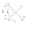
図3は、電動機の駆動電流及び回転数と、電動機のトルクとの関係を説明するための模式図である。図3は、本実施形態において、図2に示すブレーキアクチュエータ50の第1ポンプ56A及び第2ポンプ56Bを駆動する電動機55の駆動電流Id及び回転数Nと、電動機55のトルクTとの関係を示している。本実施形態に係る制動制御では、ブレーキ液加圧手段である第1ポンプ56A及び第2ポンプ56Bを駆動する負荷、すなわち、電動機55の負荷に関するパラメータに基づいて、ブレーキの操作状態を判定する。ブレーキの操作状態には、ブレーキの操作、すなわち車両100の運転者によるブレーキペダル20に対する操作の有無や、ブレーキペダル20に対する踏力のようなブレーキペダル20に対する操作状態量等が含まれる。
FIG. 3 is a schematic diagram for explaining the relationship between the drive current and rotation speed of the electric motor and the torque of the electric motor. FIG. 3 shows the relationship between the drive current Id and the rotational speed N of the
電動機55の負荷に関するパラメータは、例えば、電動機55のトルクTになる。すなわち、第1ポンプ56A及び第2ポンプ56Bを駆動する負荷が大きくなると、電動機55のトルクTが増加する。図3に示すように、電動機55の駆動電流Idが増加すると電動機55のトルクTは増加する。また、電動機55のトルクTが増加すると電動機55の回転数(電動機回転数)Nは低下する。無負荷、すなわち電動機55のトルクT0(=0)における電動機回転数はNnrであり、電動機55の負荷、すなわちトルクTの増加とともに電動機回転数Nは低下し、電動機55のトルクが最大のトルクTmaxになると、電動機回転数はN0(=0)になる。また、電動機55が無負荷のとき駆動電流Idは最小値Idminとなり、電動機の負荷が最大、すなわち、電動機55のトルクが最大のトルクTmaxになると、駆動電流Idは最大値Idmaxとなる。
The parameter relating to the load of the
本実施形態に係る制動制御では、制動装置101が備える少なくとも一つのブレーキ操作検出手段に異常があった場合には、図1に示す制動制御装置1が備えるブレーキ液加圧手段制御部1bがブレーキ液加圧手段である第1ポンプ56A及び第2ポンプ56Bを常時駆動する。すなわち、ブレーキの操作の有無に関わらず、第1ポンプ56A及び第2ポンプ56Bが駆動される。例えば、図1に示す車両100のイグニッションスイッチがONになっている間は、第1ポンプ56A及び第2ポンプ56Bが駆動される。あるいは、車両100が内燃機関を搭載する場合、内燃機関の運転中は第1ポンプ56A及び第2ポンプ56Bが駆動される。そして、図1に示す制動制御装置1が備えるブレーキ操作判定部1cは、第1ポンプ56A及び第2ポンプ56Bを駆動する負荷に関するパラメータに基づいて、ブレーキ操作を判定する。
In the braking control according to the present embodiment, when there is an abnormality in at least one brake operation detecting means provided in the
図2に示すブレーキアクチュエータ50の構成から、ブレーキの操作がない場合には第1液圧伝達系統51A及び第2液圧伝達系統51B内のブレーキ液に圧力は作用していないので、電動機55により第1ポンプ56A及び第2ポンプ56Bを駆動する負荷はほぼ0である。一方、ブレーキの操作があった場合、図2に示すブレーキアクチュエータ50の構成から分かるように、マスタシリンダ44内の液圧が高くなるので、第1液圧伝達系統51A及び第2液圧伝達系統51B内の液圧が高くなる。
From the configuration of the
これによって、第1ポンプ56A及び第2ポンプ56Bの出口側の液圧が高くなるので、第1ポンプ56A及び第2ポンプ56Bを駆動する負荷が増加する。すなわち、第1ポンプ56A及び第2ポンプ56Bを駆動する電動機55の負荷が増加する。電動機55の負荷が増加すると、電動機55のトルクTが増加するので、電動機55の駆動電流Idは増加し、電動機回転数Nは低下する。このように、ブレーキの操作があると、電動機55の駆動電流Id及び電動機回転数Nが変化する。本実施形態では、第1ポンプ56A及び第2ポンプ56Bを駆動する負荷に関するパラメータとして、電動機55の駆動電流Id又は電動機回転数Nを用い、前記パラメータに基づいて、ブレーキの操作の有無を判定する。これによって、本実施形態では、新たなブレーキ操作検出手段を追加することなく、既存のセンサ類を利用してブレーキの操作の有無を検出できる。その結果、本実施形態では、新たなブレーキ操作検出手段を追加することなしに、ブレーキの操作を検出するブレーキ操作検出手段に異常があった場合でもブレーキの操作の有無を検出できる。
As a result, the hydraulic pressure on the outlet side of the
本実施形態では、例えば、電動機55のトルクTが所定の閾値Tcを超えた場合に、ブレーキ液加圧手段制御部1bはブレーキの操作があったと判定する。電動機55の駆動電流Idは電動機55のトルクTと相関があるので、電動機55の駆動電流Idが所定の閾値(駆動電流閾値)Idcよりも大きくなった場合に、ブレーキ液加圧手段制御部1bはブレーキの操作があったと判定する。また、電動機回転数Nも電動機55のトルクTと相関があるので、電動機回転数Nが所定の閾値(電動機回転数閾値)Ncよりも小さくなった場合に、ブレーキ液加圧手段制御部1bはブレーキの操作があったと判定する。このように、本実施形態では、第1ポンプ56A及び第2ポンプ56Bを駆動する負荷に関するパラメータに基づいて、ブレーキの操作を検出できる。ここで、電動機55の駆動電流Idを検出する電流計34、及び電動機回転数Nを検出するレゾルバ35、及び図1に示す制動制御装置1のブレーキ操作判定部1cが、ブレーキ操作補助検出手段として機能する。
In the present embodiment, for example, when the torque T of the
なお、本実施形態では、駆動電流Idや電動機回転数Nと所定の閾値とを比較してブレーキの操作を検出するが、駆動電流Idや電動機回転数Nの単位時間あたりの変化量を用いて、ブレーキの操作を検出してもよい。例えば、駆動電流Idの単位時間当たりの変化量が所定の閾値を超えた場合に、ブレーキ液加圧手段制御部1bはブレーキの操作があったと判定して、ブレーキの操作を検出する。
In this embodiment, the operation of the brake is detected by comparing the drive current Id and the motor rotation speed N with a predetermined threshold, but the change amount per unit time of the drive current Id and the motor rotation speed N is used. The brake operation may be detected. For example, when the amount of change per unit time of the drive current Id exceeds a predetermined threshold, the brake fluid pressurizing means
また、図2に示すブレーキアクチュエータ50の構成から、ブレーキペダル20の踏力が増加することによってマスタシリンダ44内の液圧が高くなると、第1液圧伝達系統51A及び第2液圧伝達系統51B内の液圧が高くなるので、第1ポンプ56A及び第2ポンプ56Bを駆動する負荷も増加する。このように、本実施形態で用いる第1ポンプ56A及び第2ポンプ56Bを駆動する負荷に関するパラメータは、マスタシリンダ44内の液圧と相関が高い。
Further, from the configuration of the
このため、例えば、前記パラメータ(本実施形態では電動機55の駆動電流Id又は電動機回転数N)とマスタシリンダ44内の液圧との関係を予め求めておくことにより、前記パラメータに基づいてマスタシリンダ44内の液圧を推定することもできる。これによって、マスタシリンダ圧力センサ31に異常が発生した場合であっても、電流計34やレゾルバ35の検出値を用いて、マスタシリンダ44内の液圧を推定できる。このように、本実施形態では、新たなブレーキ操作検出手段を追加することなく、既存のセンサを利用してマスタシリンダ44内の液圧も推定できる。これによって、本実施形態では、ブレーキの操作の有無のみならず、ブレーキペダル20に対する踏力のような、ブレーキの操作状態量に関する情報も得ることができる。このように、本実施形態では、ブレーキの操作状態を判定し、検出できる。次に、本実施形態に係る制動制御の手順を説明する。
Therefore, for example, the relationship between the parameter (in this embodiment, the drive current Id of the
図4は、本実施形態に係る制動制御の手順を示すフローチャートである。ここでは、電動機55の駆動電流Idを用いてブレーキの操作の有無を判定し、ブレーキの操作を検出する手順を説明する。本実施形態に係る制動制御を実行するにあたり、ステップS101において、図1に示す制動制御装置1が備える異常判定部1aは、制動装置101が備える少なくとも一つのブレーキ操作検出手段に異常があったか否かを判定する。図1、図2に示すように、制動装置101は、マスタシリンダ圧力センサ31、ストロークセンサ32、踏力検出スイッチ33をブレーキ操作検出手段として備えるので、異常判定部1aは、これらのうち少なくとも一つに異常があったか否かを判定する。
FIG. 4 is a flowchart showing a procedure of braking control according to the present embodiment. Here, a procedure for determining the presence or absence of a brake operation using the drive current Id of the
異常の判定は、例えば、これらのセンサ類から連続して0が出力されたり、これらのセンサ類が正常に動作しているときには出力し得ない値が連続して出力されたりした場合には、制動装置101が備える少なくとも一つのブレーキ操作検出手段に異常があったと判定する。また、同一の対象を検出するために複数のセンサ類が用いられる場合には、複数のセンサの検出値を比較することによって、ブレーキ操作検出手段に異常があったか否かを判定できる。ステップS101においてYesと判定された場合、すなわち異常判定部1aが、制動装置101が備える少なくとも一つのブレーキ操作検出手段に異常があったと判定した場合、ステップS102へ進む。
The determination of abnormality is, for example, when 0 is output continuously from these sensors, or when a value that cannot be output when these sensors are operating normally is output continuously, It is determined that there is an abnormality in at least one brake operation detection means provided in the
ステップS102において、図1に示す制動制御装置1が備えるブレーキ液加圧手段制御部1bは、図2に示す電動機55を駆動する。これによって、第1ポンプ56A及び第2ポンプ56Bを駆動して、ブレーキ液を第1液圧伝達系統51A及び第2液圧伝達系統51Bへ吐出する。次に、ステップS103において、図1に示す制動制御装置1が備えるブレーキ操作判定部1cは、図1、図2に示す電流計34から、現時点における電動機55の駆動電流Idを取得する。そして、ステップS104において、ブレーキ操作判定部1cは、取得した駆動電流Idと、予め定めた所定の駆動電流の閾値(駆動電流閾値)Idcとを比較する。ここで、駆動電流閾値Idcは、ブレーキの操作の有無を判定するための閾値であり、図1に示す制動制御装置1の記憶部1mに格納されている。
In step S102, the brake fluid pressurizing means
ステップS104でYesと判定された場合、すなわち、ブレーキ操作判定部1cがId>Idcであると判定した場合には、ブレーキの操作があったと判断できる。この場合、ステップS105において、図1に示す制動制御装置1が備える制動装置制御部1dは、車両100に必要な所定の制動制御、例えば、ABS制御やブレーキアシスト制御等を実行する。ステップS104でNoと判定された場合、すなわち、ブレーキ操作判定部1cがId≦Idcであると判定した場合には、ブレーキの操作はないと判断できる。この場合、ステップS105の制動制御は実行しないで、本実施形態に係る制動制御を終了する。
When it is determined Yes in step S104, that is, when the brake
次に、ステップS101に戻って説明する。ステップS101でNoと判定された場合、すなわち異常判定部1aが、制動装置101が備えるすべてのブレーキ操作検出手段に異常はないと判定した場合、ステップS106へ進む。ステップS106において、ブレーキ操作判定部1cは、ブレーキ操作検出手段からの値X、すなわち図1、図2に示すマスタシリンダ圧力センサ31、ストロークセンサ32、踏力検出スイッチ33からの出力を取得する。そして、ステップS107において、ブレーキ操作判定部1cは、取得したブレーキ操作検出手段からの値Xと、予め定めた所定のブレーキ操作判定値βとを比較する。ここで、ブレーキ操作判定値βは、ブレーキの操作の有無を判定するための閾値であり、図1に示す制動制御装置1の記憶部1mに格納されている。
Next, it returns to step S101 and demonstrates. When it is determined No in step S101, that is, when the
ステップS107でYesと判定された場合、すなわち、ブレーキ操作判定部1cがX>βであると判定した場合には、ブレーキの操作があったと判断できる。この場合、ステップS105において、制動装置制御部1dは、車両100に必要な所定の制動制御、例えば、ABS制御やブレーキアシスト制御等を実行する。ステップS107でNoと判定された場合、すなわち、ブレーキ操作判定部1cがX≦βであると判定した場合には、ブレーキ操作はないと判断できる。この場合、ステップS105の制動制御は実行しないで、本実施形態に係る制動制御を終了する。
When it is determined Yes in step S107, that is, when the brake
図5は、本実施形態に係る制動制御の他の手順を示すフローチャートである。ここでは、電動機回転数Nを用いてブレーキの操作の有無を判定し、ブレーキの操作を検出する手順を説明する。この制動制御のステップS201、ステップS202、ステップS205、ステップS206、ステップS207は、上述した制動制御のステップS101、ステップS102、ステップS105、ステップS106、ステップS107と同様なので、これらの説明は省略する。 FIG. 5 is a flowchart showing another procedure of the braking control according to the present embodiment. Here, a procedure for determining whether or not the brake is operated using the motor rotation speed N and detecting the brake operation will be described. Since step S201, step S202, step S205, step S206, and step S207 of this braking control are the same as step S101, step S102, step S105, step S106, and step S107 of the above-described braking control, description thereof will be omitted.
ステップS202で、図1に示すブレーキ液加圧手段制御部1bが、図2に示す電動機55を駆動したら、ステップS203へ進む。ステップS203において、図1に示すブレーキ操作判定部1cは、図1、図2に示すレゾルバ35から、現時点における電動機回転数Nを取得する。そして、ステップS204において、ブレーキ操作判定部1cは、取得した電動機回転数Nと、予め定めた所定の電動機回転数の閾値(電動機回転数閾値)Ncとを比較する。ここで、電動機回転数閾値Ncは、ブレーキの操作の有無を判定するための閾値であり、図1に示す制動制御装置1の記憶部1mに格納されている。
If the brake fluid pressurizing means
ステップS204でYesと判定された場合、すなわち、ブレーキ操作判定部1cがN<Ncであると判定した場合には、ブレーキの操作があったと判断できる。この場合、ステップS205に進み、車両100に必要な所定の制動制御、例えば、ABS制御やブレーキアシスト制御等が実行される。ステップS204でNoと判定された場合、すなわち、ブレーキ操作判定部1cがN≧Ncであると判定した場合には、ブレーキの操作はないと判断できる。この場合、ステップS205の制動制御は実行しないで、本実施形態に係る制動制御を終了する。
When it is determined Yes in step S204, that is, when the brake
以上、本実施形態では、少なくとも一つのブレーキ操作検出手段に異常があった場合には、制動力発生手段のブレーキ液の圧力を増加させるブレーキ液加圧手段を常時駆動するとともに、ブレーキ液加圧手段を駆動する負荷に関するパラメータに基づいて、ブレーキの操作の有無や踏力等といったブレーキの操作状態を判定する。これにより、ブレーキの操作や操作状態を検出するためのブレーキ操作検出手段を新たに追加することなく、既存のセンサ類を用いてブレーキの操作状態を検出できる。その結果、制動装置の製造コストを抑制できる。 As described above, in this embodiment, when there is an abnormality in at least one brake operation detecting means, the brake fluid pressurizing means for increasing the brake fluid pressure of the braking force generating means is always driven and the brake fluid pressurization is performed. Based on a parameter relating to a load for driving the means, a brake operation state such as the presence / absence of a brake operation and a pedaling force is determined. Thus, the brake operation state can be detected using existing sensors without newly adding a brake operation detection means for detecting the brake operation and the operation state. As a result, the manufacturing cost of the braking device can be suppressed.
以上のように、本発明に係る制動装置及び制動制御装置は、車両の制動装置に有用であり、特に、センサ類を追加することなくブレーキの操作状態を検出することに適している。 As described above, the braking device and the braking control device according to the present invention are useful for a vehicle braking device, and are particularly suitable for detecting an operation state of a brake without adding sensors.
1 制動制御装置
1a 異常判定部
1b ブレーキ液加圧手段制御部
1c ブレーキ操作判定部
1d 制動装置制御部
1m 記憶部
10FL、10FR、10RL、10RR 車輪
20 ブレーキペダル
31 マスタシリンダ圧力センサ
32 ストロークセンサ
33 踏力検出スイッチ
34 電流計
35 レゾルバ
41FL、41FR、41RL、41RR 液圧制動手段
42FL、42FR、42RL、42RR 制動手段側液圧配管
43 ブレーキブースタ
44 マスタシリンダ
50 ブレーキアクチュエータ
51A 第1液圧伝達系統
51B 第2液圧伝達系統
55 電動機
56A 第1ポンプ
56B 第2ポンプ
100 車両
101 制動装置
DESCRIPTION OF SYMBOLS 1
Claims (6)
ブレーキの操作状態を検出する少なくとも一つのブレーキ操作検出手段と、
前記制動力発生手段へ前記ブレーキ液の圧力を伝達する圧力伝達系統に接続され、前記圧力伝達系統の前記ブレーキ液に圧力を発生させるブレーキ液加圧手段と、
少なくとも一つの前記ブレーキ操作検出手段に異常があった場合には、前記ブレーキ液加圧手段を常時駆動するとともに、前記ブレーキ液加圧手段を駆動する負荷に関するパラメータに基づいて、前記ブレーキの操作状態を検出するブレーキ操作補助検出手段と、
を含むことを特徴とする制動装置。 A braking device for transmitting a force for generating the braking force via a brake fluid to a braking force generating means for generating a braking force on a wheel of the vehicle;
At least one brake operation detecting means for detecting an operation state of the brake;
A brake fluid pressurizing unit connected to a pressure transmission system for transmitting the pressure of the brake fluid to the braking force generation unit, and generating a pressure in the brake fluid of the pressure transmission system;
When there is an abnormality in at least one of the brake operation detecting means, the brake fluid pressurizing means is always driven, and the brake operation state is based on a parameter relating to a load for driving the brake fluid pressurizing means. Brake operation auxiliary detection means for detecting
The braking device characterized by including.
前記ブレーキ操作補助検出手段は、前記駆動電流値が予め定めた駆動電流閾値よりも大きい場合には、前記ブレーキの操作が発生したと判定することを特徴とする請求項1に記載の制動装置。 The brake fluid pressurizing means is a pump driven by an electric motor, and the parameter relating to the load of the brake fluid pressurizing means is a drive current value of the electric motor,
2. The braking device according to claim 1, wherein the brake operation auxiliary detection unit determines that the operation of the brake has occurred when the drive current value is larger than a predetermined drive current threshold value.
前記ブレーキ操作補助検出手段は、前記回転数が予め定めた回転数閾値よりも小さい場合には、前記ブレーキの操作が発生したと判定することを特徴とする請求項1に記載の制動装置。 The brake fluid pressurizing means is a pump driven by an electric motor, and the parameter relating to the load of the brake fluid pressurizing means is the rotational speed of the electric motor,
2. The braking device according to claim 1, wherein the brake operation auxiliary detection unit determines that the operation of the brake has occurred when the rotation speed is smaller than a predetermined rotation speed threshold value.
前記ブレーキ操作検出手段の異常の有無を判定する異常判定部と、
前記異常判定部が、前記ブレーキ操作検出手段に異常があったと判定した場合には、前記ブレーキ液加圧手段を常時駆動するブレーキ液加圧手段制御部と、
前記ブレーキ液加圧手段を駆動する負荷に関するパラメータに基づいて前記ブレーキの操作状態を判定するブレーキ操作判定部と、
を含むことを特徴とする制動制御装置。 At least one brake operation detecting means for detecting a brake operation state by transmitting a force for generating the braking force via a brake fluid to a braking force generating means for generating a braking force on a wheel provided in the vehicle; The brake operating state of the braking device includes: a brake fluid pressurizing unit that is connected to a pressure transmission system that transmits the pressure of the brake fluid to the braking force generation unit and that generates a pressure on the brake fluid of the pressure transmission system Is to detect
An abnormality determination unit for determining presence or absence of abnormality of the brake operation detection means;
When the abnormality determining unit determines that the brake operation detecting unit is abnormal, a brake fluid pressurizing unit control unit that constantly drives the brake fluid pressurizing unit;
A brake operation determination unit that determines an operation state of the brake based on a parameter related to a load that drives the brake fluid pressurizing unit;
A braking control device comprising:
前記ブレーキ操作判定部は、前記駆動電流値が予め定めた駆動電流閾値よりも大きい場合には、前記ブレーキの操作が発生したと判定することを特徴とする請求項4に記載の制動制御装置。 The brake fluid pressurizing means is a pump driven by an electric motor, and the parameter relating to the load of the brake fluid pressurizing means is a drive current value of the electric motor,
The brake control device according to claim 4, wherein the brake operation determination unit determines that the operation of the brake has occurred when the drive current value is larger than a predetermined drive current threshold.
前記ブレーキ操作判定部は、前記回転数が予め定めた回転数閾値よりも小さい場合には、前記ブレーキの操作が発生したと判定することを特徴とする請求項4に記載の制動制御装置。 The brake fluid pressurizing means is a pump driven by an electric motor, and the parameter relating to the load of the brake fluid pressurizing means is the rotational speed of the electric motor,
The braking control device according to claim 4, wherein the brake operation determination unit determines that the operation of the brake has occurred when the rotation speed is smaller than a predetermined rotation speed threshold value.
Priority Applications (1)
| Application Number | Priority Date | Filing Date | Title |
|---|---|---|---|
| JP2007267164A JP2009096236A (en) | 2007-10-12 | 2007-10-12 | Braking device and braking control device |
Applications Claiming Priority (1)
| Application Number | Priority Date | Filing Date | Title |
|---|---|---|---|
| JP2007267164A JP2009096236A (en) | 2007-10-12 | 2007-10-12 | Braking device and braking control device |
Publications (1)
| Publication Number | Publication Date |
|---|---|
| JP2009096236A true JP2009096236A (en) | 2009-05-07 |
Family
ID=40699669
Family Applications (1)
| Application Number | Title | Priority Date | Filing Date |
|---|---|---|---|
| JP2007267164A Pending JP2009096236A (en) | 2007-10-12 | 2007-10-12 | Braking device and braking control device |
Country Status (1)
| Country | Link |
|---|---|
| JP (1) | JP2009096236A (en) |
Cited By (1)
| Publication number | Priority date | Publication date | Assignee | Title |
|---|---|---|---|---|
| JP2016193652A (en) * | 2015-03-31 | 2016-11-17 | オートリブ日信ブレーキシステムジャパン株式会社 | Brake fluid pressure control device for vehicle |
Citations (5)
| Publication number | Priority date | Publication date | Assignee | Title |
|---|---|---|---|---|
| JPH092232A (en) * | 1995-06-22 | 1997-01-07 | Aisin Seiki Co Ltd | Hydraulic pressure control device |
| JPH1159380A (en) * | 1997-08-19 | 1999-03-02 | Unisia Jecs Corp | Brake device |
| JP2006193136A (en) * | 2004-12-16 | 2006-07-27 | Honda Motor Co Ltd | Brake equipment of vehicle |
| JP2007083814A (en) * | 2005-09-21 | 2007-04-05 | Bosch Corp | Brake master cylinder pressure estimating method and anti-lock brake control device |
| JP2007112160A (en) * | 2005-10-17 | 2007-05-10 | Toyota Motor Corp | Vehicle braking device and failure sensing method of vehicle braking device |
-
2007
- 2007-10-12 JP JP2007267164A patent/JP2009096236A/en active Pending
Patent Citations (5)
| Publication number | Priority date | Publication date | Assignee | Title |
|---|---|---|---|---|
| JPH092232A (en) * | 1995-06-22 | 1997-01-07 | Aisin Seiki Co Ltd | Hydraulic pressure control device |
| JPH1159380A (en) * | 1997-08-19 | 1999-03-02 | Unisia Jecs Corp | Brake device |
| JP2006193136A (en) * | 2004-12-16 | 2006-07-27 | Honda Motor Co Ltd | Brake equipment of vehicle |
| JP2007083814A (en) * | 2005-09-21 | 2007-04-05 | Bosch Corp | Brake master cylinder pressure estimating method and anti-lock brake control device |
| JP2007112160A (en) * | 2005-10-17 | 2007-05-10 | Toyota Motor Corp | Vehicle braking device and failure sensing method of vehicle braking device |
Cited By (1)
| Publication number | Priority date | Publication date | Assignee | Title |
|---|---|---|---|---|
| JP2016193652A (en) * | 2015-03-31 | 2016-11-17 | オートリブ日信ブレーキシステムジャパン株式会社 | Brake fluid pressure control device for vehicle |
Similar Documents
| Publication | Publication Date | Title |
|---|---|---|
| JP4765487B2 (en) | Brake device for vehicle | |
| US8494745B2 (en) | Motor vehicle braking system having a hydraulically actuated service braking system and an electromechanically actuated braking system | |
| US8886375B2 (en) | Control apparatus for electric vehicle | |
| EP2876007B1 (en) | Vehicle brake force generation device | |
| JP6849822B2 (en) | Electric booster and brake control device | |
| US20100174430A1 (en) | Automotive braking control apparatus and method thereof | |
| JP2009292386A (en) | Brake system | |
| KR101732832B1 (en) | Vehicle movement dynamics control method | |
| JP4193706B2 (en) | Road surface friction coefficient detector | |
| US9517758B2 (en) | Vehicle braking device | |
| JP6153857B2 (en) | Braking device for vehicle | |
| JP4396589B2 (en) | Brake control device for vehicle | |
| JP5997565B2 (en) | Brake control device | |
| JP5024072B2 (en) | Brake control device | |
| JP4581905B2 (en) | Brake device for vehicle | |
| JP6117074B2 (en) | Braking force generator for vehicle | |
| JP2009096236A (en) | Braking device and braking control device | |
| JP2002240692A (en) | Electric brake system and computer program | |
| JP5228815B2 (en) | Brake control device | |
| JP4239861B2 (en) | Vehicle behavior control device | |
| JP4978447B2 (en) | Vehicle motion control system | |
| WO2018139529A1 (en) | Electric brake device | |
| JP6300385B2 (en) | Vehicle behavior control device | |
| JP2007230342A (en) | Braking force control system | |
| JP6488215B2 (en) | Braking device for vehicle |
Legal Events
| Date | Code | Title | Description |
|---|---|---|---|
| A621 | Written request for application examination |
Free format text: JAPANESE INTERMEDIATE CODE: A621 Effective date: 20101001 |
|
| A711 | Notification of change in applicant |
Free format text: JAPANESE INTERMEDIATE CODE: A711 Effective date: 20101203 |
|
| A977 | Report on retrieval |
Effective date: 20120224 Free format text: JAPANESE INTERMEDIATE CODE: A971007 |
|
| A131 | Notification of reasons for refusal |
Effective date: 20120313 Free format text: JAPANESE INTERMEDIATE CODE: A131 |
|
| A02 | Decision of refusal |
Free format text: JAPANESE INTERMEDIATE CODE: A02 Effective date: 20120703 |