JP2009090663A - Gravure simultaneously perfecting printer - Google Patents
Gravure simultaneously perfecting printer Download PDFInfo
- Publication number
- JP2009090663A JP2009090663A JP2008241519A JP2008241519A JP2009090663A JP 2009090663 A JP2009090663 A JP 2009090663A JP 2008241519 A JP2008241519 A JP 2008241519A JP 2008241519 A JP2008241519 A JP 2008241519A JP 2009090663 A JP2009090663 A JP 2009090663A
- Authority
- JP
- Japan
- Prior art keywords
- gravure
- printing
- layer
- plate
- photosensitive composition
- Prior art date
- Legal status (The legal status is an assumption and is not a legal conclusion. Google has not performed a legal analysis and makes no representation as to the accuracy of the status listed.)
- Pending
Links
Images


Abstract
Description
本発明は、板状被印刷材料への両面同時印刷、例えば段ボール等の粗面に両面同時印刷したり、あるいはコンパクトディスク等に画像を両面同時印刷したり、あるいは液晶パネル用ガラスへカラーフィルタを構成するためのマトリックス画像をカラー印刷するのに好適なクッション性を有するグラビア版胴を一対備えたグラビア両面同時印刷装置に関し、さらに、当該印刷装置を用いて製造されるグラビア印刷物、マイクロレンズ、壁紙、電磁波シールドシート、カラーフィルタ、偏光板、コンデンサー、電子ペーパー等に関する。 The present invention provides simultaneous double-sided printing on a plate-shaped printing material, for example, simultaneous double-sided printing on a rough surface such as cardboard, or simultaneous double-sided printing of images on a compact disk, etc. The present invention relates to a gravure double-sided simultaneous printing apparatus provided with a pair of gravure printing cylinders having cushioning properties suitable for color printing of a matrix image for composition, and further, gravure printed matter, microlens, and wallpaper produced using the printing apparatus , Electromagnetic wave shield sheet, color filter, polarizing plate, condenser, electronic paper and the like.
グラビア印刷では、グラビア製版ロール(グラビアシリンダー)に対し、製版情報に応じた微小な凹部(グラビアセル)を形成して版面を製作し当該グラビアセルにインキを充填して被印刷物に転写するものである。一般的なグラビア製版ロールにおいては、アルミニウムや鉄などの版母材の表面に版面形成用の銅メッキ層(版材)を設け、該銅メッキ層にエッチングによって製版情報に応じ多数の微小な凹部(グラビアセル)を形成し、次いでグラビア製版ロールの耐刷力を増すためのクロムメッキによって硬質のクロム層を形成して表面強化被覆層とし、製版(版面の製作)が完了する。 In gravure printing, for a gravure printing roll (gravure cylinder), a micro concave portion (gravure cell) corresponding to the plate making information is formed to produce a plate surface, and the gravure cell is filled with ink and transferred to a printing material. is there. In a general gravure plate-making roll, a copper plating layer (plate material) for forming a plate surface is provided on the surface of a plate base material such as aluminum or iron, and a number of minute concave portions are formed on the copper plating layer according to plate making information by etching. (Gravure cell) is formed, and then a hard chromium layer is formed by chromium plating for increasing the printing durability of the gravure plate making roll to form a surface-enhanced coating layer, and plate making (plate surface production) is completed.
従来、印刷版、特に、液晶パネル用ガラスへカラーフィルタを構成するためのマトリックス画像をカラー印刷したり、あるいはコンパクトディスク等に画像をカラー印刷するには、グラビアオフセット印刷または水なしオフセット印刷が採用されてきており、グラビア印刷は採用されてこなかった。その理由は、グラビア印刷は、グラビア版胴がクッション性がないので印圧が増大するとガラスを割ってしまったり、コンパクトディスク等に歪みを与えるおそれがあるからである。 Conventionally, gravure offset printing or waterless offset printing has been adopted for color printing of matrix images for forming color filters on printing plates, especially glass for liquid crystal panels, or color printing of images on compact discs, etc. Gravure printing has not been adopted. The reason for this is that gravure printing has a cushioning property of the gravure printing cylinder, so that if the printing pressure is increased, the glass may be broken or a compact disk or the like may be distorted.
そこで、この種の従来の印刷装置50は、図7に示すように、表面に多数のグラビアセル52を形成したグラビア版胴54からガラス板等の硬脆性の板状被印刷材料56に対して直接印刷することはなく、ゴムからなるブランケットロール58を介して印刷することにより、印圧が増大するときはゴムの変形により印圧の増大を抑制できるグラビアオフセット印刷が採用されていた。図8において、60はドクターブレード、62はインクである。
Therefore, as shown in FIG. 7, this type of
液晶パネル用ガラスへカラー印刷するには、ガラスに転移した直後のウエットのインキの膜厚を均一な5〜6μmとして、ドライなインキの膜厚を均一な1〜1.5μmとして、バックライト光を均一に透過しかつ高い透過率を保障する必要がある。また、コンパクトディスク等に画像をカラー印刷するには、画像がシャープに得られる限度にインキの膜厚を可能な限り薄くする必要がある。その理由は、コンパクトディスク等に印刷する画像は、中心に対して偏って印刷されるので、画像を形成しているインキの重量が、次世代のコンパクトディスク装置の流体動圧軸受を採用したスピンドルモータの高速回転化にともなって、アンバランス回転の原因として無視できなくなることが分かったからである。 For color printing on glass for liquid crystal panels, the thickness of the wet ink film immediately after transfer to the glass is set to a uniform 5-6 μm, and the dry ink film thickness is set to a uniform 1-1.5 μm. It is necessary to ensure uniform transmission and high transmittance. In addition, in order to print an image on a compact disk or the like, it is necessary to make the ink film thickness as thin as possible to the extent that the image can be obtained sharply. The reason is that the image printed on a compact disk or the like is printed with a bias with respect to the center, so the weight of the ink forming the image is the spindle that uses the fluid dynamic pressure bearing of the next generation compact disk device It is because it became clear that it became non-negligible as a cause of unbalanced rotation with high-speed rotation of a motor.
従来のグラビア印刷版は、銅メッキの表層部に深さが15〜25μmとなるようにセルを形成する必要があり、そうすると、ウエットのインキの膜厚が15〜25μmとなるから、液晶パネル用ガラスへカラー印刷する、あるいはコンパクトディスク等に画像をカラー印刷するのにはインキの膜厚が厚すぎて適していない。 In conventional gravure printing plates, it is necessary to form cells in the surface layer portion of copper plating so that the depth is 15 to 25 μm. Then, the film thickness of the wet ink is 15 to 25 μm. The ink film is too thick for color printing on glass or color printing of images on compact discs.
従来のグラビア印刷版において、銅メッキの表面に深さが5〜6μmとなるようにエッチングし、セルをエッチング形成できないのは、セルの大きさにより、エッチング速度にバラツキが出来、セルの深度が均一にならないためである。セルの輪郭や底面に凹凸が生じたり、大きさによって深度が異なったセルができるのは避けられない。特にシャドウ部の大きなセルについて、深さが5〜6μmとなるようにできても、ハイライト部の小さなセルについては、輪郭や底面に凹凸が生じる確率が高く、深さが5〜6μmになるようにすることはほとんど望めない。 In the conventional gravure printing plate, etching is performed so that the depth is 5 to 6 μm on the surface of the copper plating, and the cell cannot be formed by etching. The etching rate varies depending on the size of the cell. This is because it is not uniform. It is inevitable that the contour and bottom surface of the cell are uneven, and cells having different depths depending on the size are formed. In particular, even for a cell having a large shadow portion, even if the depth can be 5 to 6 μm, a cell having a small highlight portion has a high probability of irregularities on the contour and bottom surface, and the depth is 5 to 6 μm. I can hardly hope to do so.
そこで、セルの深さが5〜6μmのグラビア版を確実に得るには、ガラスに画像を焼き付けて現像しフッ酸によりエッチングすることにより深さが均一なかなり正確なセルを形成することができる。ただし、これは、グラビア印刷とはならず、ブランケットロールを介して印刷を行うグラビアオフセット印刷となる。 Therefore, in order to reliably obtain a gravure plate having a cell depth of 5 to 6 μm, a fairly accurate cell having a uniform depth can be formed by printing an image on glass, developing it, and etching with hydrofluoric acid. . However, this is not gravure printing but gravure offset printing in which printing is performed via a blanket roll.
こうして、従来は、液晶パネル用ガラスへカラー印刷したり、あるいはコンパクトディスク等にカラー印刷するには、グラビアオフセット印刷、または水なし平版オフセット印刷が採用されてきており、グラビア印刷は採用されてこなかった。 Thus, conventionally, gravure offset printing or waterless lithographic offset printing has been adopted for color printing on glass for liquid crystal panels or color printing on compact discs, etc., but gravure printing has not been adopted. It was.
他方、従来のフレキソ版(樹脂凸版)は、光硬化性樹脂にマスクフィルムを重ねて、紫外線で露光するか、または半導体サーマルレーザ、YAGレーザ等を照射して現像する、又は光硬化性樹脂にカーボンブラックの被膜を塗布し、レーザーでカーボンブラックを焼飛ばしてポジ画像を形成し、紫外線により最初の光硬化性樹脂を焼き付けて現像することにより製版している。 On the other hand, a conventional flexographic plate (resin relief plate) is developed by applying a mask film on a photocurable resin and exposing it with ultraviolet rays, or irradiating with a semiconductor thermal laser, a YAG laser or the like, or developing a photocurable resin. A plate of carbon black is applied, carbon black is burned off with a laser to form a positive image, and the first photocurable resin is baked and developed with ultraviolet rays to make a plate.
しかしながら、従来の印刷法によって製作される液晶パネル用カラーフィルタは、画像のシャープさが低く、線画像のエッジの乱れ、線画像の凹凸があり、フィルム法によって製作される液晶パネル用カラーフィルタに比べて著しく品質が劣り、このため、玩具関係にしか用途が広がらず、TFTの付いているコンピュータディスプレイや液晶テレビジョン等の高級品には全く採用されていない。 However, the color filter for liquid crystal panels manufactured by the conventional printing method has low image sharpness, the edge of the line image is irregular, and the line image has irregularities. The quality is remarkably inferior to that of the above, and therefore, its use is widespread only for toys, and it is not used at all for high-end products such as computer displays and liquid crystal televisions with TFTs.
グラビアオフセット印刷によって製作される液晶パネル用カラーフィルタの品質が劣る原因は、次のように考えられる。グラビアオフセット印刷は、ブランケットロールからガラス等の被印刷物にインキを転移させる際に多少なりとも印圧が加わる。該印圧は、インキを押圧するので、インキの輪郭が外側に広がりあるいは乱れ、これが、解像性或いは精細性の指標として用いるラインアンドスペースの数値を小さくできない原因の一つである。また、転移するインキが版からブランケットロールに、さらにブランケットロールからガラス等の被印刷物に、それぞれ100%の確率で転移しないときは、インキが引きちぎられる結果となり、ガラス等の被印刷物に印刷されるインキの膜厚は均一でなく表面に凹凸ができる。 The reason why the quality of the color filter for a liquid crystal panel manufactured by gravure offset printing is inferior is considered as follows. In gravure offset printing, a printing pressure is applied to some extent when ink is transferred from a blanket roll to a substrate such as glass. Since the printing pressure presses the ink, the contour of the ink spreads outward or is disturbed, which is one of the reasons why the line and space value used as an indicator of resolution or fineness cannot be reduced. In addition, when the transferred ink does not transfer from the plate to the blanket roll and from the blanket roll to the printed material such as glass with a probability of 100%, the ink is torn off and printed on the printed material such as glass. The ink film thickness is not uniform and the surface is uneven.
グラビアオフセット印刷機械の高精度をいくら追求しても、印圧をかける必要があり、印圧の変動を抑えることは不可能である。従って、印圧がかかり、印圧が変動することが必須なので、ブランケットロールから液晶パネル用ガラスに100%の確率でインキを転移させることは、実験ではできたとしても、実用化はとても困難であると考えられる。 No matter how high the precision of a gravure offset printing machine is pursued, it is necessary to apply printing pressure, and it is impossible to suppress fluctuations in printing pressure. Therefore, since it is essential that printing pressure is applied and the printing pressure fluctuates, it is very difficult to put it into practical use even if it is possible to transfer ink from the blanket roll to the liquid crystal panel glass with a probability of 100%. It is believed that there is.
他方、従来のフレキソ版(樹脂凸版)は、光硬化性樹脂を使用しているので、ちいさなドットを柱状に形成すると容易に折損してしまい、硬化樹脂の脆性を解消できず、高精細な版を作ることができなかった。 On the other hand, the conventional flexographic plate (resin relief plate) uses a photo-curing resin, so if a small dot is formed in a columnar shape, it easily breaks, and the brittleness of the cured resin cannot be eliminated. Could not make.
本発明は、クッション性を有するグラビア版胴を一対用いることにより、硬脆性な被印刷物に対してブランケットロールを用いないダイレクトな両面同時グラビア印刷を可能とすることによって両面に異なる画像を同時印刷できかつ印刷効率を倍増することができ、段ボール印刷等、粗面に対するグラビア両面同時印刷が良好に行えて、液晶パネル用ガラスへカラーフィルタを構成するためのマトリックス画像をカラー印刷する、あるいはコンパクトディスク等に画像をカラー印刷するのに好適であるクッション性を有するグラビア版胴を備えたグラビア両面同時印刷装置を提供することを目的としている。さらに本発明は、当該印刷装置を用いて製造されるグラビア印刷物、マイクロレンズ、壁紙、電磁波シールドシート、カラーフィルタ、偏光板、コンデンサー、電子ペーパー等を提供することを目的としている。 By using a pair of gravure printing cylinders having cushioning properties, the present invention can simultaneously print different images on both sides by enabling direct double-sided simultaneous gravure printing without using a blanket roll on a hard and brittle substrate. In addition, printing efficiency can be doubled, and gravure double-sided simultaneous printing on rough surfaces, such as corrugated cardboard printing, can be performed satisfactorily, and matrix images for configuring color filters on liquid crystal panel glass can be printed in color, compact discs, etc. Another object of the present invention is to provide a gravure double-sided simultaneous printing apparatus provided with a gravure printing cylinder having cushioning properties suitable for color printing of images. Furthermore, an object of the present invention is to provide a gravure printed material, a microlens, a wallpaper, an electromagnetic wave shielding sheet, a color filter, a polarizing plate, a capacitor, electronic paper, and the like manufactured using the printing apparatus.
上記課題を解決するため、本発明のグラビア両面同時印刷装置は、板状被印刷材料の表面及び裏面の両面に対するグラビア両面同時印刷装置であって、該板状被印刷材料を一定方向に搬送進行させる搬送手段と、該進行する被印刷材料の表面及び裏面に当接可能に設置されかつ版面にグラビアセルを設けたクッション性を有する一対のグラビア版胴と、該一対のグラビア版胴の版面にそれぞれ接触可能に設けられたドクターブレードと、を含み、前記一対のグラビア版胴に供給されるインクを前記ドクターブレードによって前記グラビアセルに貯留せしめ、該一対のグラビア版胴を回転させるとともに前記板状被印刷材料を一定方向に進行させた状態で該一対のグラビア版胴を該板状被印刷材料の表面及び裏面に当接させることによって前記グラビアセルに貯留されたインクを前記板状被印刷材料の表面及び裏面に直接転写して該板状被印刷材料の表面及び裏面に同時にグラビア印刷を行うようにしたことを特徴とする。 In order to solve the above problems, the gravure double-sided simultaneous printing device of the present invention is a gravure double-sided simultaneous printing device for both the front and back surfaces of a plate-like printing material, and the plate-like printing material is conveyed in a certain direction. Conveying means, a pair of gravure printing cylinders that are installed so as to be in contact with the front and back surfaces of the material to be printed and have a gravure cell on the printing plate, and a plate surface of the pair of gravure printing drums A doctor blade provided in contact with each other, the ink supplied to the pair of gravure plate cylinders is stored in the gravure cell by the doctor blade, the pair of gravure plate cylinders are rotated and the plate-like By bringing the pair of gravure plate cylinders into contact with the front and back surfaces of the plate-like printing material in a state where the printing material is advanced in a certain direction, The ink stored in Rabiaseru is characterized in that to perform simultaneously gravure printing on the surface and the back surface of the plate-like printed material is transferred directly to the front and back surfaces of the plate-like printed material.
前記クッション性を有するグラビア版胴の第1の態様は、ゴム又はクッション性を有する樹脂からなるクッション層を表面に設けた版母材と、該クッション層の表面に形成された感光性組成物層と、該感光性組成物層の表面に形成されたグラビアセルと、該グラビアセルを形成した感光性組成物層の表面に形成された強化被覆層と、を含むものである。 The first aspect of the gravure plate cylinder having cushioning properties includes a plate base material provided with a cushion layer made of rubber or a resin having cushioning properties on the surface, and a photosensitive composition layer formed on the surface of the cushion layer. And a gravure cell formed on the surface of the photosensitive composition layer, and a reinforcing coating layer formed on the surface of the photosensitive composition layer on which the gravure cell is formed.
前記感光性組成物層がネガ型感光性組成物を用いて形成されてなることが好ましい。
該ネガ型感光性組成物の第1の態様としては、(A)カルボキシル基を有し且つエチレン性不飽和結合を有するポリマーと、(B)近赤外線吸収色素と、(C)少なくとも1個のエチレン性不飽和結合を有するモノマーと、(D)アミノアルコール、アミノアルコールの誘導体及び環状アミンからなる群から選択される1種以上のアミン類と、(E)有機ホウ素化合物と、(F)下記式(1)で示されるスルホニル化合物と、を含有する組成を採用することが好適である。
It is preferable that the photosensitive composition layer is formed using a negative photosensitive composition.
As a first aspect of the negative photosensitive composition, (A) a polymer having a carboxyl group and having an ethylenically unsaturated bond, (B) a near-infrared absorbing dye, and (C) at least one A monomer having an ethylenically unsaturated bond; (D) one or more amines selected from the group consisting of amino alcohols, amino alcohol derivatives and cyclic amines; (E) organoboron compounds; and (F) It is preferable to employ a composition containing a sulfonyl compound represented by the formula (1).

[式(1)中、Qはアリール基又はヘテロ環基を示し、X1〜X3は各々独立してハロゲン原子を示す] Wherein (1), Q represents an aryl group or a heterocyclic group, a halogen atom X 1 to X 3 are each independently]
前記アミノアルコールの誘導体が、アミノアルコールの(メタ)アクリル酸エステルであるのが好ましい。また、前記環状アミンが、モルホリノ基含有化合物又はピペラジン系化合物であることが好適である。なお、本願明細書において、アクリルとメタクリルをあわせて(メタ)アクリルと称し、アクリレートとメタクリレートをあわせて(メタ)アクリレートと称する。 The amino alcohol derivative is preferably a (meth) acrylic acid ester of amino alcohol. Moreover, it is preferable that the cyclic amine is a morpholino group-containing compound or a piperazine-based compound. In the present specification, acrylic and methacryl are collectively referred to as (meth) acrylic, and acrylate and methacrylate are collectively referred to as (meth) acrylate.
前記式(1)で示される化合物(F)が、トリブロモメチルフェニルスルホン又は2−[(トリブロモメチル)スルホニル]ピリジンであることが好ましい。 The compound (F) represented by the formula (1) is preferably tribromomethylphenyl sulfone or 2-[(tribromomethyl) sulfonyl] pyridine.
前記ネガ型感光性組成物の第2の態様としては、(A)カルボキシル基を有し且つエチレン性不飽和結合を有するポリマーと、(B)近赤外線吸収色素と、(C)少なくとも1個のエチレン性不飽和結合を有するモノマーと、(G)2−メルカプトベンゾオキサゾール及び/又は2−メルカプトオキサゾールと、(H)下記式(2)で示されるジフェニルヨードニウム塩と、を含有する組成を採用することが好適である。 As a second aspect of the negative photosensitive composition, (A) a polymer having a carboxyl group and having an ethylenically unsaturated bond, (B) a near-infrared absorbing dye, (C) at least one A composition containing a monomer having an ethylenically unsaturated bond, (G) 2-mercaptobenzoxazole and / or 2-mercaptooxazole, and (H) a diphenyliodonium salt represented by the following formula (2) is adopted. Is preferred.
前記ネガ型感光性組成物の第2の態様が、(I)下記一般式(3)で示されるトリアジン化合物をさらに含有することが好ましい。 It is preferable that the second aspect of the negative photosensitive composition further contains (I) a triazine compound represented by the following general formula (3).
[前記一般式(3)において、R1はビニル基又はビニル基を含む1価の有機基である] [In the general formula (3), R 1 is a vinyl group or a monovalent organic group containing a vinyl group]
前記(I)トリアジン化合物が、2,4−ジアミノ−6−ビニル−s−トリアジン及び/又は2,4−ジアミノ−6−メタクリロイルオキシエチル−s−トリアジンであることが好適である。 The (I) triazine compound is preferably 2,4-diamino-6-vinyl-s-triazine and / or 2,4-diamino-6-methacryloyloxyethyl-s-triazine.
前記ネガ型感光性組成物の第1及び第2の態様が、(J)シランカップリング剤をさらに含有することが好ましい。 The first and second aspects of the negative photosensitive composition preferably further contain (J) a silane coupling agent.
前記ネガ型感光性組成物の第1及び第2の態様が、(K)重合禁止剤をさらに含有することが好適である。 It is preferable that the first and second aspects of the negative photosensitive composition further contain (K) a polymerization inhibitor.
前記クッション性を有するグラビア版胴の第2の態様は、ゴム又はクッション性を有する樹脂からなるクッション層を表面に設けた版母材と、該クッション層の表面に形成されたグラビアセルと、該グラビアセルを形成したクッション層の表面に形成された強化被覆層と、を含むものである。 The second aspect of the gravure plate cylinder having the cushioning property includes a plate base material provided with a cushion layer made of rubber or a resin having cushioning property on the surface, a gravure cell formed on the surface of the cushion layer, And a reinforcing coating layer formed on the surface of the cushion layer on which the gravure cell is formed.
前記クッション性を有するグラビア版胴の第3の態様は、ゴム又はクッション性を有する樹脂からなるクッション層を表面に設けた版母材と、該クッション層の表面に形成された銅メッキ層と、該銅メッキ層にエッチングによって形成されたグラビアセルと、該グラビアセルを形成した銅メッキ層の表面に形成された強化被覆層と、を含むものである。 The third aspect of the gravure plate cylinder having cushioning properties is a plate base material provided with a cushion layer made of rubber or a resin having cushioning properties on the surface, a copper plating layer formed on the surface of the cushion layer, A gravure cell formed by etching on the copper plating layer and a reinforcing coating layer formed on the surface of the copper plating layer on which the gravure cell is formed are included.
前記クッション性を有するグラビア版胴の第4の態様は、ゴム又はクッション性を有する樹脂からなるクッション層を表面に設けた版母材と、該クッション層の表面に形成された銅メッキ層と、該銅メッキ層の表面に金属メッキ層からなるグラビアセル壁体を形成することによって形成されたグラビアセルと、該グラビアセルを形成した銅メッキ層及び金属メッキ層の表面に形成された強化被覆層と、を含むことを含むものである。 The fourth aspect of the gravure plate cylinder having the cushioning property is a plate base material provided with a cushion layer made of rubber or a resin having cushioning property on the surface, a copper plating layer formed on the surface of the cushion layer, A gravure cell formed by forming a gravure cell wall made of a metal plating layer on the surface of the copper plating layer, a copper plating layer on which the gravure cell is formed, and a reinforcing coating layer formed on the surface of the metal plating layer Including.
本発明の印刷物は、本発明の印刷装置を用いて製造されることを特徴とする。
前記印刷物としては、被印刷物シートの表面に水性インキ、油性インキ又は相変化インキからなるグラビアインキを印刷により所定のパターンを形成するように配置することによってグラビア印刷される印刷物であって、本発明の印刷装置を用いて前記グラビアインキの印刷を行うようにした印刷物が好適である。
The printed matter of the present invention is manufactured using the printing apparatus of the present invention.
The printed matter is a printed matter that is gravure-printed by arranging a gravure ink composed of water-based ink, oil-based ink, or phase change ink so as to form a predetermined pattern by printing on the surface of the sheet to be printed. A printed material in which the gravure ink is printed using the printing apparatus is suitable.
本発明のマイクロレンズは、シート状基材の表面にマイクロレンズ形成用インキを印刷により所定間隔を保って突条状に配置することによって製造されるマイクロレンズであって、本発明の印刷装置を用いて前記マイクロレンズ形成用インキの印刷を行うようにしたことを特徴とする。 The microlens of the present invention is a microlens manufactured by arranging microlens forming ink on a surface of a sheet-like base material in a protruding shape at a predetermined interval by printing, and the printing apparatus of the present invention The ink for microlens formation is used for printing.
本発明の壁紙は、壁紙基材の表面に壁紙用インキを印刷により所定のパターンを形成するように配置することによって製造される壁紙であって、本発明の印刷装置を用いて前記壁紙用インキの印刷を行うようにしたことを特徴とする。 The wallpaper of the present invention is a wallpaper produced by arranging the ink for wallpaper on the surface of the wallpaper substrate so as to form a predetermined pattern by printing, and the wallpaper ink using the printing apparatus of the present invention This is characterized in that printing is performed.
本発明の電磁波シールドシートは、電磁波シールド基材の表面に導電性ペーストを印刷により所定パターンの電磁波シールド層を形成するように配置することによって製造される電磁波シールドシートであって、本発明の印刷装置を用いて前記導電性ペーストの印刷を行うようにしたことを特徴とする。 The electromagnetic wave shielding sheet of the present invention is an electromagnetic wave shielding sheet produced by disposing a conductive paste on a surface of an electromagnetic wave shielding substrate so as to form an electromagnetic wave shielding layer having a predetermined pattern by printing, The conductive paste is printed using an apparatus.
本発明のカラーフィルタは、カラーフィルタ基材の表面にカラーフィルタインキを印刷により所定パターンのカラーフィルタ層を形成するように配置することによって製造されるカラーフィルタであって、本発明の印刷装置を用いて前記カラーフィルタインキの印刷を行うようにしたことを特徴とする。 The color filter of the present invention is a color filter manufactured by arranging a color filter ink on a surface of a color filter substrate so as to form a color filter layer having a predetermined pattern by printing, and the printing apparatus of the present invention The color filter ink is used for printing.
本発明の偏光板は、偏光板基材の表面に偏光インキを印刷により所定パターンの偏光層を形成するように配置することによって製造される偏光板であって、本発明の印刷装置を用いて前記偏光インキの印刷を行うようにしたことを特徴とする。 The polarizing plate of the present invention is a polarizing plate produced by arranging a polarizing ink on the surface of a polarizing plate substrate so as to form a polarizing layer having a predetermined pattern by printing, and using the printing apparatus of the present invention. The polarizing ink is printed.
本発明のセラミックコンデンサは、セラミック基材上に導電性ペーストを印刷により内部電極を形成するように配置することによって製造されるセラミックコンデンサであって、本発明の印刷装置を用いて前記導電性ペーストの印刷を行うようにしたことを特徴とする。 The ceramic capacitor of the present invention is a ceramic capacitor manufactured by arranging a conductive paste on a ceramic substrate so as to form an internal electrode by printing, and the conductive paste using the printing apparatus of the present invention. This is characterized in that printing is performed.
本発明の電子ペーパーは、基材フィルム上に磁性粉を含有するマイクロカプセル化セルをバインダーを介して塗布することにより所定のパターンを形成するように配置することによって製造される電子ペーパーであって、本発明の印刷装置を用いて前記マイクロカプセル化セルを塗布するようにしたことを特徴とする。 The electronic paper of the present invention is an electronic paper manufactured by arranging a microencapsulated cell containing magnetic powder on a base film so as to form a predetermined pattern by applying it through a binder. The microencapsulated cell is applied using the printing apparatus of the present invention.
本発明のクッション性を有するグラビア版胴を備えたグラビア印刷装置によれば、硬質な被印刷物に対してブランケットロールを用いないダイレクトな両面同時グラビア印刷を可能とすることによって両面に異なる画像を同時印刷できかつ印刷効率を倍増することができ、液晶パネル用ガラスへカラーフィルタを構成するためのマトリックス画像をカラー印刷したり、あるいはコンパクトディスク等に画像をカラー印刷するのに好適であり、また、段ボール印刷等、粗面に対する印刷も良好にできる。さらに、本発明の印刷装置を用いることによって、印刷物、マイクロレンズ、壁紙、電磁波シールドシート、カラーフィルタ、偏光板、コンデンサー、電子ペーパー等の製造において、インキ材料や塗布材料の微細転写や微細転移が容易となり、性能に優れた最終製品を得ることが可能となる。 According to the gravure printing apparatus equipped with the gravure printing cylinder having cushioning properties of the present invention, it is possible to simultaneously print different images on both sides by enabling direct double-sided simultaneous gravure printing without using a blanket roll on a hard substrate. It can be printed and the printing efficiency can be doubled. It is suitable for color printing a matrix image for constituting a color filter on glass for a liquid crystal panel, or for color printing an image on a compact disk, etc. Printing on rough surfaces such as cardboard printing can also be performed well. Furthermore, by using the printing apparatus of the present invention, in the production of printed matter, microlens, wallpaper, electromagnetic wave shield sheet, color filter, polarizing plate, capacitor, electronic paper, etc., fine transfer and fine transfer of ink materials and coating materials are possible. It becomes easy and it becomes possible to obtain a final product with excellent performance.
特に、本発明装置のグラビア版胴の製造に好適に用いられる前述した第1及び第2の態様のネガ型感光性組成物は、露光前のバーニング及びオーバーコートが不要であり、優れた感度、密着性及び保存安定性を有するもので、このネガ型感光性組成物を用いてフォトリソグラフィを利用して形成されたグラビアセルはグラビア印刷に対応しうる実用性のあるシャープなグラビアセル形状を有するという著大な効果を有する。 In particular, the negative photosensitive composition of the first and second aspects described above that is preferably used for the production of the gravure plate cylinder of the apparatus of the present invention does not require burning and overcoat before exposure, and has excellent sensitivity, A gravure cell that has adhesion and storage stability and is formed using photolithography using this negative photosensitive composition has a sharp gravure cell shape that is practical and compatible with gravure printing. It has a remarkable effect.
以下に本発明の実施の形態を説明するが、これら実施の形態は例示的に示されるもので、本発明の技術思想から逸脱しない限り種々の変形が可能なことはいうまでもない。 Embodiments of the present invention will be described below, but these embodiments are exemplarily shown, and it goes without saying that various modifications can be made without departing from the technical idea of the present invention.
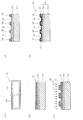
図1は本発明のグラビア両面同時印刷装置の実施形態の一例を示す断面的説明図である。
図1において、50Aは本発明のグラビア両面同時印刷装置で、ガラス板やダンボール等の板状被印刷材料56を一定方向に搬送進行させる搬送手段57と、該進行する被印刷材料56の表面56a及び裏面56bに当接可能に設置されかつ版面にグラビアセル14a,14bをそれぞれ設けたクッション性を有する一対のグラビア版胴10a,10bとを有している。60a,60bは該一対のグラビア版胴10a,10bの版面にそれぞれ接触可能に設けられたドクターブレードである。
FIG. 1 is a sectional explanatory view showing an example of an embodiment of a gravure double-sided simultaneous printing apparatus of the present invention.
In FIG. 1, 50A is a gravure double-sided simultaneous printing apparatus of the present invention, a conveying
上記構成により、前記一対のグラビア版胴10a,10bに供給されるインク62a,62bを前記ドクターブレード60a,60bによって前記グラビアセル14a,14bに貯留せしめ、該一対のグラビア版胴10a,10bを回転させるとともに前記板状被印刷材料を一定方向に進行させた状態で該一対のグラビア版胴10a,10bを該板状被印刷材料56の表面56a及び裏面56bに当接させることによって前記グラビアセル14a,14bに貯留されたインク62a,62bを前記板状被印刷材料56の表面56a及び裏面56bに直接転写して該板状被印刷材料56の表面56a及び裏面56bに同時にグラビア印刷を行うものである。
With the above configuration, the
このように一対のグラビア版胴10a,10bとしてクッション性を有するグラビア版胴を用いることによって、液晶パネル用ガラスへカラーフィルタを構成するためのマトリックス画像をカラー印刷する際などのように硬脆性のガラス板等に対する印刷を、従来のようにブランケットロールを介在させることなくダイレクトに効率よく行うことができ、また表面に凹凸のあるダンボール等に対する印刷も効果的に行うことができるものである。特に、本発明装置においては、一対のグラビア版胴10a,10bを用いることによって、硬脆性な被印刷物に対してブランケットロールを用いないダイレクトな両面同時グラビア印刷を可能とすることによって両面に異なる画像を同時印刷できかつ印刷効率を倍増することができるという利点を有するものである。
Thus, by using a gravure plate cylinder having cushioning properties as a pair of
前記クッション性を有するグラビア版胴10a,10bの態様としては、グラビア版胴がクッション性を有すればよいもので、特別の限定はないが、次の4つの態様を採用することができる。なお、グラビア版胴10a,10bは同一の構造であるので、以下に述べる図2〜図6では、グラビア版胴10aのみについて言及して説明し、グラビアセル14a,14bについてはグラビアセル14として説明する。
The
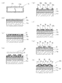
前記クッション性を有するグラビア版胴10aの第1の態様は、図2(e)及び図3(e)に示すように、ゴム又はクッション性を有する樹脂からなるクッション層11bを表面に設けた版母材10と、該クッション層の表面に形成された感光性組成物層12と、該感光性組成物層12の表面に形成されたグラビアセル14と、該グラビアセル14を形成した感光性組成物層12の表面に形成された強化被覆層18とを含むものである。
As shown in FIGS. 2 (e) and 3 (e), the first aspect of the
図2は本発明のグラビア両面同時印刷装置に用いられるクッション性を有するグラビア版胴10aの第1の態様の製造方法の工程の一例を模式的に示す説明図で、(a)はゴム又はクッション性を有する樹脂からなるクッション層を表面に形成した中空ロール(版母材)の全体断面図、(b)はクッション層の表面にネガ型感光性組成物層を形成した状態を示す部分拡大断面図、(c)はネガ型感光性組成物層の表面にマスクを設けた状態を示す部分拡大断面図、(d)はネガ型感光性組成物層の表面にグラビアセルを形成した状態を示す部分拡大断面図、(e)はネガ型感光性組成物層の表面に強化被覆層を形成した状態を示す部分拡大断面図である。図3は本発明のグラビア両面同時印刷装置に用いられるクッション性を有するグラビア版の第1の態様の製造方法の工程の他の例を示す図2と同様の図面である。
FIG. 2 is an explanatory view schematically showing an example of the steps of the manufacturing method of the first aspect of the
まず、ゴム又はクッション性を有する樹脂からなるクッション層を表面に設けた版母材を準備する。図2(a)において、符号10は版母材であり、中空ロール11aの表面にクッション層11bを設けたものが用いられる。該クッション層11bは、ゴム又はクッション性を有する樹脂からなり、1mm〜10cm程度の均一な厚さで表面の平滑度が高いシート状のものを、継ぎ目に隙間が開かないように中空ロール11aに巻付け強固に接着し、その後精密円筒研削、鏡面研磨される。前記中空ロール11aが、アルミニウム、鉄等の金属製又は炭素繊維強化樹脂(CFRP)製であることが好適である。
First, a plate base material provided with a cushion layer made of rubber or a resin having cushioning properties on the surface is prepared. In FIG. 2 (a),
次に、前記クッション層11bの表面に感光性組成物層12を形成する[図2(b)]。感光性組成物層12の膜厚については特別の限定はなく、版の使用目的と関連してセルの深さに対応して決める。
Next, a
例えば、段ボール印刷等ではグラビアセルの深さを1mm以上とすることがあるので、ネガ型感光性組成物層12の膜厚はそれよりも数mm厚くする。
For example, since the depth of the gravure cell may be 1 mm or more in corrugated cardboard printing or the like, the film thickness of the negative
例えば、液晶パネル用ガラスへカラーフィルタを構成するためのマトリックス画像をカラー印刷するには、インキ膜厚が均一になるようにするため、グラビアセルを均一な5〜6μmの深さに形成する必要がある。従って、感光性組成物層12をコーティングにより5〜6μmの厚さとなるように形成して、クッション層11bが露出するようにセルを形成する。さらに好ましくは、クッション層11bをシリコンゴムにより形成してセルに盛られるインキの液晶パネル用ガラスへの転移性を高めるのが良い。
For example, in order to color-print a matrix image for forming a color filter on a glass for a liquid crystal panel, it is necessary to form a gravure cell to a uniform depth of 5 to 6 μm in order to make the ink film thickness uniform. There is. Therefore, the
コンパクトディスク等も極めて薄いインキ膜厚となるのが良いので、セルの深さを数μmとする。感光性組成物層12の膜厚は、1〜2mmでも良いし、又は5〜6μmの薄膜としても良い。要は、感光性組成物層12の形成の容易性、コスト、現像との関連で適宜に決定できる。
Since a compact disc or the like should have a very thin ink film thickness, the cell depth is set to several μm. The film thickness of the
前記感光性組成物層は、感光性組成物を用いて形成される。該感光性組成物としては、ネガ型及びポジ型のいずれでも使用可能であるが、ネガ型感光性組成物を用いることが好ましい。前記ネガ型感光性組成物は特に制限はなく、公知のネガ型感光性組成物を用いることができるが、後述する第1及び第2の態様のネガ型感光性組成物を用いることが好適である。 The photosensitive composition layer is formed using a photosensitive composition. As the photosensitive composition, either a negative type or a positive type can be used, but it is preferable to use a negative photosensitive composition. There is no restriction | limiting in particular in the said negative photosensitive composition, Although a well-known negative photosensitive composition can be used, It is suitable to use the negative photosensitive composition of the 1st and 2nd aspect mentioned later. is there.
前記ネガ型感光性組成物の第1の態様として、(A)カルボキシル基を有し且つエチレン性不飽和結合を有するポリマーと、(B)近赤外線吸収色素と、(C)少なくとも1個のエチレン性不飽和結合を有するモノマーと、(D)アミノアルコール、アミノアルコールの誘導体及び環状アミンからなる群から選択される1種以上のアミン類と、(E)有機ホウ素化合物と、(F)下記式(1)で示されるスルホニル化合物と、を含有する組成を採用することが好適である。 As a first aspect of the negative photosensitive composition, (A) a polymer having a carboxyl group and having an ethylenically unsaturated bond, (B) a near-infrared absorbing dye, and (C) at least one ethylene A monomer having a polar unsaturated bond, (D) one or more amines selected from the group consisting of amino alcohols, amino alcohol derivatives and cyclic amines, (E) organoboron compounds, and (F) the following formula It is preferable to employ a composition containing the sulfonyl compound represented by (1).
[式(1)中、Qはアリール基又はヘテロ環基を示し、X1〜X3は各々独立してハロゲン原子を示す] Wherein (1), Q represents an aryl group or a heterocyclic group, a halogen atom X 1 to X 3 are each independently]
前記ポリマー(A)としては、カルボキシル基及びエチレン性不飽和結合を有するポリマーであれば特に限定されないが、例えば、カルボキシル基を有する不飽和化合物を単量体単位として有する(共)重合体を、エチレン性不飽和結合を有する化合物と反応させることにより得られるポリマーが好適に用いられる。前記ポリマー(A)は、カルボキシル基を酸価が30〜500、特に、200〜250になるように含むことが好ましい。重量平均分子量としては1,500〜100,000が好適で好ましく、6,000〜50,000前後のものが更に好ましい。 The polymer (A) is not particularly limited as long as it is a polymer having a carboxyl group and an ethylenically unsaturated bond. For example, a (co) polymer having an unsaturated compound having a carboxyl group as a monomer unit, A polymer obtained by reacting with a compound having an ethylenically unsaturated bond is preferably used. The polymer (A) preferably contains a carboxyl group so that the acid value is 30 to 500, particularly 200 to 250. The weight average molecular weight is preferably 1,500 to 100,000, more preferably around 6,000 to 50,000.
前記カルボキシル基を有する不飽和化合物としては、(メタ)アクリル酸、マレイン酸、フマール酸、イタコン酸、及びそれらの誘導体等が好ましく、これらを単独又は2種以上を組み合わせて使用することができる。 As the unsaturated compound having a carboxyl group, (meth) acrylic acid, maleic acid, fumaric acid, itaconic acid, and derivatives thereof are preferable, and these can be used alone or in combination of two or more.
カルボキシル基を有する不飽和化合物を単量体単位として有する(共)重合体は、単量体単位として、前記カルボキシル基を有する不飽和化合物以外の他の不飽和化合物を併用してもよい。該他の不飽和化合物としては、不飽和二重結合を有する化合物が好ましく、スチレン、α−メチルスチレン、m又はp−メトキシスチレン、p−メチルスチレン、p−ヒドロキシスチレン、3−ヒドロキシメチル−4−ヒドロキシ−スチレン等のスチレン系単量体や、(メタ)アクリル酸メチル、(メタ)アクリル酸エチル、(メタ)アクリル酸ブチル、ヒドロキシエチル(メタ)アクリレート等の(メタ)アクリル酸エステルがより好ましい。これらを単独又は2種以上組み合わせて使用することができる。 The (co) polymer having an unsaturated compound having a carboxyl group as a monomer unit may be used in combination with another unsaturated compound other than the unsaturated compound having a carboxyl group as a monomer unit. As the other unsaturated compound, a compound having an unsaturated double bond is preferable, and styrene, α-methylstyrene, m or p-methoxystyrene, p-methylstyrene, p-hydroxystyrene, 3-hydroxymethyl-4. -Styrenic monomers such as hydroxy-styrene, and (meth) acrylic acid esters such as methyl (meth) acrylate, ethyl (meth) acrylate, butyl (meth) acrylate, hydroxyethyl (meth) acrylate, etc. preferable. These can be used alone or in combination of two or more.
前記エチレン性不飽和結合を有する化合物としては、例えば、不飽和アルコール(例えば、アリルアルコール、2−ブテン−1−2−オール、フルフリルアルコール、オレイルアルコール、シンナミルアルコール、2−ヒドロキシエチルアクリレート、ヒドロキシエチルメタクリレート、N−メチロールアクリルアミド等),アルキル(メタ)アクリレート(例えば、メチルメタクリレート、t−ブチルメタクリレート等),オキシラン環及びエチレン性不飽和結合をそれぞれ1個有するエポキシ化合物(例えば、グリシジルアクリレート、グリシジルメタクリレート、アリルグリシジルエーテル、α−エチルグリシジルアクリレート、クロトニルグリシジルエーテル、イタコン酸モノアルキルモノグリシジルエステル等)等が好適な例として挙げられる。 Examples of the compound having an ethylenically unsaturated bond include unsaturated alcohols (for example, allyl alcohol, 2-buten-1--2-ol, furfuryl alcohol, oleyl alcohol, cinnamyl alcohol, 2-hydroxyethyl acrylate, Hydroxyethyl methacrylate, N-methylolacrylamide, etc.), alkyl (meth) acrylate (eg, methyl methacrylate, t-butyl methacrylate, etc.), epoxy compound having one oxirane ring and one ethylenically unsaturated bond (eg, glycidyl acrylate, Suitable examples include glycidyl methacrylate, allyl glycidyl ether, α-ethyl glycidyl acrylate, crotonyl glycidyl ether, itaconic acid monoalkyl monoglycidyl ester, and the like. And the like.
また、上記ポリマー(A)として、不飽和アルコールによりエチレン性不飽和結合を導入されたものに、さらにエチレン性不飽和結合濃度を大きくするために、前記したオキシラン環及びエチレン性不飽和結合をそれぞれ1個有するエポキシ化合物を反応させ、さらにエチレン性不飽和結合濃度を大きくしたものを用いてもよい。 Further, as the polymer (A), in order to further increase the concentration of the ethylenically unsaturated bond in the polymer having the ethylenically unsaturated bond introduced by the unsaturated alcohol, the above-described oxirane ring and ethylenically unsaturated bond are respectively You may use what reacted the epoxy compound which has one, and also enlarged the ethylenically unsaturated bond density | concentration.
前記ネガ型感光性組成物の第1の態様における前記ポリマー(A)の含有割合は、特に限定されないが、組成物の固形分総量に対して、45〜65重量%であるのが好ましく、50〜60重量%であるのが更に好ましい。前記ポリマー(A)は単独で用いてもよく、2種以上組み合わせて用いてもよい。 The content ratio of the polymer (A) in the first aspect of the negative photosensitive composition is not particularly limited, but is preferably 45 to 65% by weight based on the total solid content of the composition, 50 More preferred is -60% by weight. The polymer (A) may be used alone or in combination of two or more.
前記(B)近赤外線吸収色素としては、波長700〜1,100nmの赤外線領域の一部又は全部に吸収帯を有する有機又は無機の色素が挙げられ、前記波長域の光を効率良く吸収し、且つ紫外線領域の光は殆ど吸収しないか又は吸収しても実質的に感応しない光吸収色素が好ましく、下記一般式(4)で示される化合物及びその誘導体、下記式(5)で示されるポリメチン系化合物(例えば、特開2001−64255号及びWO2005/049736号等参照)等がより好適に用いられる。 Examples of the (B) near-infrared absorbing dye include organic or inorganic dyes having an absorption band in part or all of the infrared region having a wavelength of 700 to 1,100 nm, efficiently absorbing light in the wavelength region, In addition, a light-absorbing dye that absorbs almost no light in the ultraviolet region or is substantially insensitive even when absorbed is preferable, a compound represented by the following general formula (4) and a derivative thereof, and a polymethine type represented by the following formula (5) Compounds (for example, see JP-A No. 2001-64255 and WO 2005/049736) and the like are more preferably used.
[前記一般式(4)において、R2〜R5は各々独立して、水素原子、アルコキシル基、又は3級アミノ基であり、メトキシ基、−N(CH3)2、又は−N(C2H5)2が好ましい。X−は対アニオンを示し、XとしてはC4H9−B(C6H5)3、p−CH3C6H4SO3、又はCF3SO3等が好ましい。] [In General Formula (4), R 2 to R 5 are each independently a hydrogen atom, an alkoxyl group, or a tertiary amino group, and include a methoxy group, —N (CH 3 ) 2 , or —N (C 2 H 5) 2 is preferred. X - is represents a counter anion, as the X C 4 H 9 -B (C 6 H 5) 3, p-CH 3 C 6 H 4 SO 3, or CF 3 SO 3 and the like are preferable. ]
[前記一般式(5)において、R6は水素原子、置換基を有してもよいアルキル基又は置換基を有してもよいアルコキシ基を示し、水素原子又は炭素数1〜4のアルコキシ基が好ましい。R7は水素原子、置換基を有してもよいアルキル基又は置換基を有してもよいアルコキシ基を示し、炭素数1〜8のアルキル基、総炭素数2〜8のアルコキシアルキル基、炭素数1〜8のスルホアルキル基、又は総炭素数2〜9のカルボキシアルキル基が好ましい。R8及びR9はそれぞれ炭素数1〜4のアルキル基を示し、メチル基が好ましく、またR8とR9は互いに連結して環状構造を形成してもよく、シクロペンタン環又はシクロヘキサン環を形成していることが好ましい。Y1は水素原子、置換基を有してもよいアルコキシ基又は置換基を有してもよいアルキル基を示し、水素原子、炭素数1〜4のアルコキシ基又は炭素数1〜4のアルキル基が好ましい。Y2は水素原子、ハロゲン原子又は置換アルキル基を示し、H、Cl、Br又はジフェニルアミノ基が好ましい。Zは電荷中和イオンを示し、Cl−、Br−、I−、ClO4 −、BF4 −、CF3CO2 −、PF6 −、SbF6 −、CH3SO3 −又はp−トルエンスルホネート、Na+、K+、トリエチルアンモニウムイオンが好ましい。] [In the general formula (5), R 6 represents a hydrogen atom, an alkyl group which may have a substituent or an alkoxy group which may have a substituent, and a hydrogen atom or an alkoxy group having 1 to 4 carbon atoms. Is preferred. R 7 represents a hydrogen atom, an optionally substituted alkyl group or an optionally substituted alkoxy group, an alkyl group having 1 to 8 carbon atoms, an alkoxyalkyl group having 2 to 8 carbon atoms in total, A sulfoalkyl group having 1 to 8 carbon atoms or a carboxyalkyl group having 2 to 9 carbon atoms is preferable. R 8 and R 9 each represent an alkyl group having 1 to 4 carbon atoms, preferably a methyl group, and R 8 and R 9 may be linked to each other to form a cyclic structure, and a cyclopentane ring or a cyclohexane ring It is preferable to form. Y 1 represents a hydrogen atom, an alkoxy group which may have a substituent or an alkyl group which may have a substituent, a hydrogen atom, an alkoxy group having 1 to 4 carbon atoms or an alkyl group having 1 to 4 carbon atoms. Is preferred. Y 2 represents a hydrogen atom, a halogen atom or a substituted alkyl group, and is preferably H, Cl, Br or a diphenylamino group. Z represents a charge neutralizing ion, and Cl − , Br − , I − , ClO 4 − , BF 4 − , CF 3 CO 2 − , PF 6 − , SbF 6 − , CH 3 SO 3 − or p-toluenesulfonate. , Na + , K + , and triethylammonium ion are preferable. ]
また、他の光吸収色素としては、例えば、特開平11−231515号公報に記載されているような窒素原子、酸素原子、又は硫黄原子等を含む複素環等がポリメチン(−CH=)nで結合された、広義の所謂シアニン系色素が代表的なものとして挙げられ、具体的には、例えば、キノリン系(所謂、シアニン系)、インドール系(所謂、インドシアニン系)、ベンゾチアゾール系(所謂、チオシアニン系)、イミノシクロヘキサジエン系(所謂、ポリメチン系)、ピリリウム系、チアピリリウム系、スクアリリウム系、クロコニウム系、アズレニウム系等が挙げられ、中で、キノリン系、インドール系、ベンゾチアゾール系、イミノシクロヘキサジエン系、ピリリウム系、又はチアピリリウム系が好ましい。特に、フタロシアニンやシアニンが好ましい。 As other light-absorbing dyes, for example, polymethine (—CH═) n is a heterocyclic ring containing a nitrogen atom, an oxygen atom, a sulfur atom, or the like as described in JP-A-11-231515. The so-called cyanine dyes in a broad sense bound to each other can be cited as representative examples. Specifically, for example, quinoline (so-called cyanine), indole (so-called indocyanine), benzothiazole (so-called) , Thiocyanine series), iminocyclohexadiene series (so-called polymethine series), pyrylium series, thiapyrylium series, squarylium series, croconium series, azurenium series, etc. Among them, quinoline series, indole series, benzothiazole series, iminocyclo Hexadiene, pyrylium, or thiapyrylium are preferred. In particular, phthalocyanine and cyanine are preferable.
前記ネガ型感光性組成物の第1の態様における近赤外線吸収色素(B)の含有割合は、特に限定されないが、組成物の固形分総量に対して、0.2〜4.0重量%であるのが好ましく、0.4〜3.0重量%であるのが更に好ましい。前記近赤外線吸収色素(B)は単独で用いてもよく、2種以上組み合わせて用いてもよい。 Although the content rate of the near-infrared absorption pigment | dye (B) in the 1st aspect of the said negative photosensitive composition is not specifically limited, It is 0.2 to 4.0 weight% with respect to the solid content total amount of a composition. It is preferable that it is 0.4 to 3.0% by weight. The near infrared absorbing dye (B) may be used alone or in combination of two or more.
前記(C)少なくとも1個のエチレン性不飽和結合を有するモノマーとしては、エチレン性不飽和結合を分子中に1個以上有する化合物であれば特に制限はないが、例えば、メチル(メタ)アクリレート、エチル(メタ)アクリレート、n−ブチル(メタ)アクリレート、イソブチル(メタ)アクリレート、2−エチルヘキシル(メタ)アクリレート、シクロヘキシル(メタ)アクリレート等のアルキル(メタ)アクリレート、テトラヒドロフルフリル(メタ)アクリレート、フルフリル(メタ)アクリレート、ベンジル(メタ)アクリレート、2−ヒドロキシエチル(メタ)アクリレート、ジメチルアミノエチル(メタ)アクリレート、グリシジル(メタ)アクリレート、モノ(2−(メタ)アクリロイルオキシエチル)アシッドホスフェート、ジメチルアミノエチル(メタ)アクリレート四級化物、N−(メタ)アクリロイルオキシエチルヘキサヒドロフタルイミド等のイミド基又はマレイミド基を有する(メタ)アクリレート、トリメチロールプロパントリ(メタ)アクリレート、トリメチロールプロパンジ(メタ)アクリレート、トリエチレングリコールジ(メタ)アクリレート、ジエチレングリコールジ(メタ)アクリレート、テトラエチレングリコールジ(メタ)アクリレート、ヘキサメチレングリコールジ(メタ)アクリレート、ネオペンチルグリコールジ(メタ)アクリレート、テトラメチロールメタンテトラ(メタ)アクリレート、レゾルシノールジ(メタ)アクリレート、p,p’−ジヒドロキシジフェニルジ(メタ)アクリレート、スピログリコールジ(メタ)アクリレート、シクロヘキサンジメチロールジ(メタ)アクリレート、ビスフェノールAジ(メタ)アクリレート、ポリプロピレングリコールジ(メタ)アクリレート、ジペンタエリスリトールヘキサ(メタ)アクリレート、メチレンビス(メタ)アクリルアミド、ウレタン系ジ(メタ)アクリレート等が挙げられる。 The monomer (C) having at least one ethylenically unsaturated bond is not particularly limited as long as it is a compound having at least one ethylenically unsaturated bond in the molecule. For example, methyl (meth) acrylate, Alkyl (meth) acrylates such as ethyl (meth) acrylate, n-butyl (meth) acrylate, isobutyl (meth) acrylate, 2-ethylhexyl (meth) acrylate, cyclohexyl (meth) acrylate, tetrahydrofurfuryl (meth) acrylate, furfuryl (Meth) acrylate, benzyl (meth) acrylate, 2-hydroxyethyl (meth) acrylate, dimethylaminoethyl (meth) acrylate, glycidyl (meth) acrylate, mono (2- (meth) acryloyloxyethyl) acid phosphate , (Meth) acrylate having imide group or maleimide group such as dimethylaminoethyl (meth) acrylate quaternized product, N- (meth) acryloyloxyethyl hexahydrophthalimide, trimethylolpropane tri (meth) acrylate, trimethylolpropane Di (meth) acrylate, triethylene glycol di (meth) acrylate, diethylene glycol di (meth) acrylate, tetraethylene glycol di (meth) acrylate, hexamethylene glycol di (meth) acrylate, neopentyl glycol di (meth) acrylate, tetra Methylolmethane tetra (meth) acrylate, resorcinol di (meth) acrylate, p, p'-dihydroxydiphenyl di (meth) acrylate, spiroglycol di (meth) ) Acrylate, cyclohexanedimethylol di (meth) acrylate, bisphenol A di (meth) acrylate, polypropylene glycol di (meth) acrylate, dipentaerythritol hexa (meth) acrylate, methylenebis (meth) acrylamide, urethane di (meth) acrylate Etc.
前記ネガ型感光性組成物の第1の態様におけるモノマー(C)の含有割合は、特に限定されないが、組成物の固形分総量に対して、25〜46重量%であるのが好ましく、30〜40重量%であるのが更に好ましい。前記モノマー(C)は単独で用いてもよく、2種以上組み合わせて用いてもよい。 The content ratio of the monomer (C) in the first aspect of the negative photosensitive composition is not particularly limited, but is preferably 25 to 46% by weight with respect to the total solid content of the composition, 30 to More preferably, it is 40% by weight. The monomer (C) may be used alone or in combination of two or more.
前記(D)アミン類における前記アミノアルコールとしては、1分子中にアミノ基とアルコール性の水酸基とを有する有機化合物が使用可能であり、例えば、N,N−ジメチルエタノールアミン、N,N−ジエチルエタノールアミン、N,N−ジブチルエタノールアミン、N−メチルエタノールアミン、N−メチルジエタノールアミン等が好適な例として挙げられる。 As the amino alcohol in the (D) amine, an organic compound having an amino group and an alcoholic hydroxyl group in one molecule can be used, and examples thereof include N, N-dimethylethanolamine, N, N-diethyl. Preferable examples include ethanolamine, N, N-dibutylethanolamine, N-methylethanolamine, N-methyldiethanolamine and the like.
前記(D)アミン類における前記アミノアルコールの誘導体としては、アミノアルコールのエステルや塩が好ましく、ジメチルアミノエチル(メタ)アクリレート、ジエチルアミノエチル(メタ)アクリレート等のアミノアルコールと(メタ)アクリル酸とのエステルがより好ましい。 As the derivative of the amino alcohol in the (D) amines, an ester or salt of an amino alcohol is preferable, and an amino alcohol such as dimethylaminoethyl (meth) acrylate or diethylaminoethyl (meth) acrylate and (meth) acrylic acid Esters are more preferred.
前記(D)アミン類における前記環状アミンとしては、環の内外にアミン性窒素を有する化合物であれば特に制限はないが、モルホリン、N−メチルモルホリン、N−エチルモルホリン及びモルホリノエチルメタクリレート等のモルホリノ基含有化化合物や、ピペラジン、ヒドロキシエチルピペラジン及び2−メチルピペラジン等のピペラジン環を有する化合物(ピペラジン系化合物)が好ましい。 The cyclic amine in the (D) amine is not particularly limited as long as it is a compound having an amine nitrogen inside and outside the ring, but morpholino such as morpholine, N-methylmorpholine, N-ethylmorpholine and morpholinoethyl methacrylate. A group-containing compound and a compound having a piperazine ring such as piperazine, hydroxyethylpiperazine and 2-methylpiperazine (piperazine-based compound) are preferable.
前記ネガ型感光性組成物の第1の態様における前記アミン類(D)の含有割合は、特に限定されないが、組成物の固形分総量に対して、0.3〜5.0重量%であるのが好ましく、0.5〜4.0重量%であるのが更に好ましい。前記アミン類(D)は単独で用いてもよく、2種以上組み合わせて用いてもよい。 Although the content rate of the said amines (D) in the 1st aspect of the said negative photosensitive composition is not specifically limited, It is 0.3 to 5.0 weight% with respect to the solid content total amount of a composition. And is more preferably 0.5 to 4.0% by weight. The amines (D) may be used alone or in combination of two or more.
前記(E)有機ホウ素化合物としては、例えば、4級ホウ素アニオンのアンモニウム塩の構造を有するものが好ましく、具体的には、下記一般式(6)で示される構造を有する化合物が好適である。 As said (E) organic boron compound, what has the structure of the ammonium salt of a quaternary boron anion, for example is preferable, and the compound which specifically has a structure shown by following General formula (6) is suitable.
[前記一般式(6)において、R10は、1価の有機基であり、アルキル基が好ましく、n−ブチル基がより好ましい。R11〜R13は各々独立して1価の有機基であり、アリール基が好ましく、フェニル基、ナフチル基、アルキルフェニル基がより好ましい。R14〜R17は各々独立して1価の有機基であり、アルキル基が好ましい。] [In the general formula (6), R 10 is a monovalent organic group, preferably an alkyl group, and more preferably an n-butyl group. R 11 to R 13 are each independently a monovalent organic group, preferably an aryl group, and more preferably a phenyl group, a naphthyl group, or an alkylphenyl group. R 14 to R 17 are each independently a monovalent organic group, preferably an alkyl group. ]
また、前記一般式(6)で示される化合物として、下記式(7)で示される化合物が好適に用いられる。 Moreover, as the compound represented by the general formula (6), a compound represented by the following formula (7) is preferably used.
前記ネガ型感光性組成物の第1の態様における有機ホウ素化合物(E)の含有割合は、特に限定されないが、組成物の固形分総量に対して、0.3〜4.0重量%であるのが好ましく、0.5〜3.0重量%であるのが更に好ましい。前記有機ホウ素化合物(E)は単独で用いてもよく、2種以上組み合わせて用いてもよい。 The content ratio of the organoboron compound (E) in the first aspect of the negative photosensitive composition is not particularly limited, but is 0.3 to 4.0% by weight with respect to the total solid content of the composition. And is more preferably 0.5 to 3.0% by weight. The organoboron compound (E) may be used alone or in combination of two or more.
(F)前記式(1)で示されるスルホニル化合物において、Qはアリール基又はヘテロ環基であり、アリール基は単環のアリール基及び多環のアリール基のいずれでもよく、また置換されていてもよい。前記アリール基としては、例えば、置換又は非置換のベンゼン環、置換又は非置換のナフタレン環が挙げられ、フェニレン基が好ましい。
前記ヘテロ環基は単環又は多環のヘテロ環基であり、芳香族のヘテロ環基が好ましく、他のアリール基と縮環していてもよい。前記ヘテロ環基としては、例えば、ピリジン環、ピリミジン環、イミダゾール環、ピラゾール環、キノリン環、イソキノリン環、ベンズイミダゾール環、チアゾール環、ベンゾチアゾール環等が挙げられ、ピリジン環がより好ましい。
前記スルホニル化合物(F)としては、具体的には、トリブロモメチルフェニルスルホン又は2−[(トリブロモメチル)スルホニル]ピリジンがより好ましい。
(F) In the sulfonyl compound represented by the formula (1), Q is an aryl group or a heterocyclic group, and the aryl group may be either a monocyclic aryl group or a polycyclic aryl group, and is substituted. Also good. Examples of the aryl group include a substituted or unsubstituted benzene ring and a substituted or unsubstituted naphthalene ring, and a phenylene group is preferable.
The heterocyclic group is a monocyclic or polycyclic heterocyclic group, preferably an aromatic heterocyclic group, and may be condensed with other aryl groups. Examples of the heterocyclic group include a pyridine ring, a pyrimidine ring, an imidazole ring, a pyrazole ring, a quinoline ring, an isoquinoline ring, a benzimidazole ring, a thiazole ring, and a benzothiazole ring, and a pyridine ring is more preferable.
Specifically, the sulfonyl compound (F) is more preferably tribromomethylphenyl sulfone or 2-[(tribromomethyl) sulfonyl] pyridine.
前記ネガ型感光性組成物の第1の態様におけるスルホニル化合物(F)の含有割合は、特に限定されないが、組成物の固形分総量に対して、0.1〜5.0重量%であるのが好ましく、0.3〜4.0重量%であるのが更に好ましい。前記スルホニル化合物(F)は単独で用いてもよく、2種以上組み合わせて用いてもよい。 The content ratio of the sulfonyl compound (F) in the first aspect of the negative photosensitive composition is not particularly limited, but is 0.1 to 5.0% by weight with respect to the total solid content of the composition. Is preferable, and it is further more preferable that it is 0.3 to 4.0 weight%. The said sulfonyl compound (F) may be used independently and may be used in combination of 2 or more type.
前記ネガ型感光性組成物の第1の態様は、(J)シランカップリング剤をさらに含有することが好ましい。前記(J)シランカップリング剤を添加することにより、密着性を向上させることができる。前記(J)シランカップリング剤としては、反応性官能基を有するアルコキシシラン化合物が好ましく、例えば、ビニルトリクロルシラン、ビニルトリメトキシシラン及びビニルトリエトキシシラン等のビニル基を有するアルコキシシラン化合物、2−(3,4−エポキシシクロへキシル)エチルトリメトキシシラン、3−グリシドキシプロピルトリメトキシシラン、3−グリシドキシプロピルメチルジエトキシシラン及び3−グリシドキシプロピルトリエトキシシラン等のエポキシ基を含有するアルコキシシラン化合物、p−スチリルトリメトキシシラン等のスチリル基を有するアルコキシシラン化合物、3−メタクリロキシプロピルメチルジメトキシシラン、3−メタクリロキシプロピルトリメトキシシラン、3−メタクリロキシプロピルメチルジエトキシシラン及び3−メタクリロキシプロピルトリエトキシシラン等のメタクリロキシ基を有するアルコキシシラン化合物、3−アクリロキシプロピルトリメトキシシラン等のアクリロキシ基を有するアルコキシシラン化合物、N−2(アミノエチル)3−アミノプロピルメチルジメトキシシラン、N−2(アミノエチル)3−アミノプロピルトリメトキシシラン、N−2(アミノエチル)3−アミノプロピルトリエトキシシラン、3−アミノプロピルトリメトキシシラン、3−アミノプロピルトリエトキシシラン、3−トリエトキシシリル−N−(1,3−ジメチルブチリデン)プロピルアミン、N−フェニル−3−アミノプロピルトリメトキシシラン、及びN−(ビニルベンジル)−2−アミノエチル−3−アミノプロピルトリメトキシシランの塩酸塩等のアミノ基を有するアルコキシシラン化合物、3−ウレイドプロピルトリエトキシシラン等のウレイド基を有するアルコキシシラン化合物、3−クロロプロピルトリメトキシシラン等のクロロプロピル基を有するアルコキシシラン化合物、3−メルカプトプロピルメチルジメトキシシラン及び3−メルカプトプロピルトリメトキシシラン等のメルカプト基を有するアルコキシシラン化合物、ビス(トリエトキシシリルプロピル)テトラスルフィド等のスルフィド基を有するアルコキシシラン化合物、3−イソシアネートプロピルトリエトキシシラン等のイソシアネート基を有するアルコキシシラン化合物、イミダゾールシラン等のイミダゾール基を有するアルコキシシラン化合物が挙げられ、特に、イミダゾール基を有するアルコキシシラン化合部が、ニッケルやステンレス等の鏡面基材に対する密着性をより向上させることができ好ましい。 The first aspect of the negative photosensitive composition preferably further comprises (J) a silane coupling agent. Adhesion can be improved by adding the (J) silane coupling agent. The (J) silane coupling agent is preferably an alkoxysilane compound having a reactive functional group, for example, an alkoxysilane compound having a vinyl group such as vinyltrichlorosilane, vinyltrimethoxysilane, or vinyltriethoxysilane, 2- Epoxy groups such as (3,4-epoxycyclohexyl) ethyltrimethoxysilane, 3-glycidoxypropyltrimethoxysilane, 3-glycidoxypropylmethyldiethoxysilane and 3-glycidoxypropyltriethoxysilane Contained alkoxysilane compounds, alkoxysilane compounds having a styryl group such as p-styryltrimethoxysilane, 3-methacryloxypropylmethyldimethoxysilane, 3-methacryloxypropyltrimethoxysilane, 3-methacryloxypropiyl Alkoxysilane compounds having a methacryloxy group such as methyldiethoxysilane and 3-methacryloxypropyltriethoxysilane, alkoxysilane compounds having an acryloxy group such as 3-acryloxypropyltrimethoxysilane, N-2 (aminoethyl) 3- Aminopropylmethyldimethoxysilane, N-2 (aminoethyl) 3-aminopropyltrimethoxysilane, N-2 (aminoethyl) 3-aminopropyltriethoxysilane, 3-aminopropyltrimethoxysilane, 3-aminopropyltriethoxy Silane, 3-triethoxysilyl-N- (1,3-dimethylbutylidene) propylamine, N-phenyl-3-aminopropyltrimethoxysilane, and N- (vinylbenzyl) -2-aminoethyl-3-amino Propyl Alkoxysilane compounds having an amino group such as hydrochloride of rmethoxysilane, alkoxysilane compounds having a ureido group such as 3-ureidopropyltriethoxysilane, and alkoxysilane compounds having a chloropropyl group such as 3-chloropropyltrimethoxysilane Alkoxysilane compounds having a mercapto group such as 3-mercaptopropylmethyldimethoxysilane and 3-mercaptopropyltrimethoxysilane, alkoxysilane compounds having a sulfide group such as bis (triethoxysilylpropyl) tetrasulfide, 3-isocyanatopropyltri Examples include alkoxysilane compounds having an isocyanate group such as ethoxysilane, and alkoxysilane compounds having an imidazole group such as imidazolesilane. An alkoxysilane compound having a group is preferable because it can further improve the adhesion to a mirror surface substrate such as nickel or stainless steel.
前記ネガ型感光性組成物の第1の態様におけるシランカップリング剤(J)の含有割合は、特に限定されないが、組成物の固形分総量に対して、0〜3.0重量%であるのが好ましく、0.3〜2.0重量%であるのが更に好ましい。前記シランカップリング剤(J)は単独で用いてもよく、2種以上組み合わせて用いてもよい。 The content ratio of the silane coupling agent (J) in the first aspect of the negative photosensitive composition is not particularly limited, but is 0 to 3.0% by weight based on the total solid content of the composition. Is preferable, and it is still more preferable that it is 0.3 to 2.0 weight%. The said silane coupling agent (J) may be used independently and may be used in combination of 2 or more type.
前記ネガ型感光性組成物は、(K)重合禁止剤をさらに含むことが好適である。重合禁止剤としては、エチレン性不飽和結合含有基の重合を抑制しうる化合物であればよいが、例えば、ハイドロキノン、2,5−ジ−t−ブチルハイドロキノン、2,5−ジ−t−アミルハイドロキノン、2,5−ビス(1,1,3,3−テトラメチルブチル)ハイドロキノン等のハイドロキノン系化合物;4−メトキシフェノール、2,6−ジ−t−ブチル−4−メチルフェノール、4,4’−ブチリデンビス(3−メチル−6−t−ブチルフェノール)、2,2’−メチレンビス(4−メチル−6−t−ブチルフェノール)、2,2’−メチレンビス(4−エチル−6−t−ブチルフェノール)等のフェノール類;フェノチアジン及びフェノチアジン誘導体等のフェノチアジン系化合物;ジブチルジチオカルバミン酸銅等のジチオカルバミン酸塩;N−ニトロソフェニルヒドロキシルアミン、N−ニトロソフェニルヒドロキシルアミンアルミニウム塩等のニトロソ系化合物;2−メルカプトベンゾチアゾール、2−ベンゾチアゾリルジスルフィド、2−メルカプトベンゾチアゾールの亜鉛塩、N−シクロヘキシル−2−ベンゾチアゾールスルフェンアミド、N,N−ジシクロヘキシル−2−ベンゾチアゾールスルフェンアミド、N−オキシジエチレン−2−ベンゾチアゾールスルフェンアミド、N−t−ブチル−2−ベンゾチアゾールスルフェンアミド、2(4−モルフォリニルジチオ)ベンゾチアゾール等のチアゾール系化合物が挙げられ、チアゾール系化合物がより好ましい。 The negative photosensitive composition preferably further comprises (K) a polymerization inhibitor. The polymerization inhibitor may be any compound that can suppress the polymerization of the ethylenically unsaturated bond-containing group. For example, hydroquinone, 2,5-di-t-butylhydroquinone, 2,5-di-t-amyl Hydroquinone compounds such as hydroquinone and 2,5-bis (1,1,3,3-tetramethylbutyl) hydroquinone; 4-methoxyphenol, 2,6-di-t-butyl-4-methylphenol, 4,4 '-Butylidenebis (3-methyl-6-t-butylphenol), 2,2'-methylenebis (4-methyl-6-t-butylphenol), 2,2'-methylenebis (4-ethyl-6-t-butylphenol) Phenols such as: phenothiazine compounds such as phenothiazine and phenothiazine derivatives; dithiocarls such as copper dibutyldithiocarbamate Minates; nitroso compounds such as N-nitrosophenylhydroxylamine and N-nitrosophenylhydroxylamine aluminum salts; 2-mercaptobenzothiazole, 2-benzothiazolyl disulfide, zinc salt of 2-mercaptobenzothiazole, N- Cyclohexyl-2-benzothiazole sulfenamide, N, N-dicyclohexyl-2-benzothiazole sulfenamide, N-oxydiethylene-2-benzothiazole sulfenamide, Nt-butyl-2-benzothiazole sulfenamide Examples include thiazole compounds such as 2 (4-morpholinyldithio) benzothiazole, and thiazole compounds are more preferable.
前記ネガ型感光性組成物の第1の態様における重合禁止剤(K)の含有割合は、特に限定されないが、組成物の固形分総量に対して、0.1〜7重量%であるのが好ましく、0.1〜5重量%であるのが更に好ましい。前記重合禁止剤(K)は単独で用いてもよく、2種以上組み合わせて用いてもよい。 The content of the polymerization inhibitor (K) in the first aspect of the negative photosensitive composition is not particularly limited, but is 0.1 to 7% by weight based on the total solid content of the composition. Preferably, it is 0.1 to 5 weight%. The said polymerization inhibitor (K) may be used independently and may be used in combination of 2 or more type.
また、本発明で用いられる前記ネガ型感光性組成物の第2の態様として、(A)カルボキシル基を有し且つエチレン性不飽和結合を有するポリマーと、(B)近赤外線吸収色素と、(C)少なくとも1個のエチレン性不飽和結合を有するモノマーと、(G)2−メルカプトベンゾオキサゾール及び/又は2−メルカプトオキサゾールと、(H)下記式(2)で示されるジフェニルヨードニウム塩と、を含有する組成を採用することが好適である。 Further, as a second aspect of the negative photosensitive composition used in the present invention, (A) a polymer having a carboxyl group and having an ethylenically unsaturated bond, (B) a near infrared absorbing dye, C) a monomer having at least one ethylenically unsaturated bond, (G) 2-mercaptobenzoxazole and / or 2-mercaptooxazole, and (H) a diphenyliodonium salt represented by the following formula (2): It is preferable to adopt the composition to be contained.
前記ネガ型感光性組成物の第2の態様における、(A)カルボキシル基を有し且つエチレン性不飽和結合を有するポリマー、(B)近赤外線吸収色素、及び(C)少なくとも1個のエチレン性不飽和結合を有するモノマーは、前記第1の態様のネガ型感光性組成物と同様の成分であり、これら成分の具体例や含有割合については前述した内容と同様であるので再度の説明は省略する。 In the second embodiment of the negative photosensitive composition, (A) a polymer having a carboxyl group and having an ethylenically unsaturated bond, (B) a near-infrared absorbing dye, and (C) at least one ethylenic compound The monomer having an unsaturated bond is the same component as in the negative photosensitive composition of the first aspect, and the specific examples and content ratios of these components are the same as those described above, so that the description thereof is omitted. To do.
前記成分(G)は、2−メルカプトベンゾオキサゾール、2−メルカプトオキサゾール、又は両者の併用であり、連鎖移動剤として用いられる。前記ネガ型感光性組成物の第2の態様における成分(G)の含有割合は、特に限定されないが、組成物の固形分総量に対して、0.5〜20重量%であるのが好ましく、3〜15重量%であるのが更に好ましい。 The component (G) is 2-mercaptobenzoxazole, 2-mercaptooxazole, or a combination of both, and is used as a chain transfer agent. The content ratio of the component (G) in the second aspect of the negative photosensitive composition is not particularly limited, but is preferably 0.5 to 20% by weight based on the total solid content of the composition, More preferably, it is 3 to 15% by weight.
前記成分(H)は、前記式(2)で示されるジフェニルヨードニウム塩であり、光開始剤として用いられる。前記ネガ型感光性組成物の第2の態様における成分(H)の含有割合は、特に限定されないが、組成物の固形分総量に対して、0.5〜20.0重量%であるのが好ましく、4.0〜15.0重量%であるのが更に好ましい。 The component (H) is a diphenyliodonium salt represented by the formula (2) and is used as a photoinitiator. Although the content rate of the component (H) in the 2nd aspect of the said negative photosensitive composition is not specifically limited, It is 0.5-20.0 weight% with respect to the solid content total amount of a composition. It is preferably 4.0 to 15.0% by weight.
前記ネガ型感光性組成物の第2の態様は、(I)下記一般式(3)で示されるトリアジン化合物をさらに含有することが好ましい。 The second aspect of the negative photosensitive composition preferably further comprises (I) a triazine compound represented by the following general formula (3).
前記一般式(3)において、R1はビニル基又はビニル基を含む1価の有機基であり、ビニル基又は(メタ)アクリロイルオキシアルキル基が好ましい。前記(I)トリアジン化合物としては、2,4−ジアミノ−6−ビニル−s−トリアジン及び/又は2,4−ジアミノ−6−メタクリロイルオキシエチル−s−トリアジン等が好適な例として挙げられる。 In the general formula (3), R 1 is a vinyl group or a monovalent organic group containing a vinyl group, preferably a vinyl group or a (meth) acryloyloxyalkyl group. Preferred examples of the (I) triazine compound include 2,4-diamino-6-vinyl-s-triazine and / or 2,4-diamino-6-methacryloyloxyethyl-s-triazine.
前記ネガ型感光性組成物の第2の態様における成分(I)の含有割合は、特に限定されないが、組成物の固形分総量に対して、0.1〜5.0重量%であるのが好ましく、0.2〜4.0重量%であるのが更に好ましい。前記(I)トリアジン化合物は単独で用いてもよく、2種以上組み合わせて用いてもよい。 The content ratio of component (I) in the second aspect of the negative photosensitive composition is not particularly limited, but is 0.1 to 5.0% by weight based on the total solid content of the composition. Preferably, it is 0.2 to 4.0 weight%. The (I) triazine compounds may be used alone or in combination of two or more.
前記ネガ型感光性組成物の第2の態様において、前記ネガ型感光性組成物の第1の態様における成分である(D)アミノアルコール、アミノアルコールの誘導体及び環状アミンからなる群から選択される1種以上のアミン類をさらに含有することが好適である。このアミン類の具体例や含有割合については前述した内容と同様であるので再度の説明は省略する。 In the second aspect of the negative photosensitive composition, the negative photosensitive composition is selected from the group consisting of (D) amino alcohol, a derivative of amino alcohol, and a cyclic amine, which are components in the first aspect of the negative photosensitive composition. It is preferred to further contain one or more amines. Since specific examples and content ratios of the amines are the same as those described above, the description thereof will be omitted.
前記ネガ型感光性組成物の第2の態様において、前記ネガ型感光性組成物の第1の態様の場合と同様に(J)シランカップリング剤をさらに含有するのが好ましい。このシランカップリング剤の具体例や含有割合については前述した内容と同様であるので再度の説明は省略する。 In the second aspect of the negative photosensitive composition, it is preferable that the composition further contains (J) a silane coupling agent as in the case of the first aspect of the negative photosensitive composition. Since specific examples and content ratios of the silane coupling agent are the same as those described above, description thereof will be omitted.
前記ネガ型感光性組成物の第2の態様において、前記ネガ型感光性組成物の第1の態様の場合と同様に(K)重合禁止剤をさらに含有するのが好ましい。この重合禁止剤の具体例や含有割合については前述した内容と同様であるので再度の説明は省略する。 In the second aspect of the negative photosensitive composition, it is preferable that the composition further contains (K) a polymerization inhibitor as in the case of the first aspect of the negative photosensitive composition. Since specific examples and content ratios of the polymerization inhibitor are the same as those described above, the description thereof will be omitted.
前記ネガ型感光性組成物(第1及び第2の態様を含めて)は、上記した成分に加えて、必要に応じて、顔料又は染料等の着色剤、増感剤、現像促進剤、密着性改質剤、塗布性改良剤、表面調整剤等の各種添加剤を配合してもよい。 In addition to the above components, the negative photosensitive composition (including the first and second embodiments) may include a colorant such as a pigment or a dye, a sensitizer, a development accelerator, and an adhesion as necessary. Various additives such as a property modifier, a coating property improver, and a surface conditioner may be blended.
現像促進剤は、例えば、ジカルボン酸又はアミン類又はグリコール類を微量添加することが好ましい。 The development accelerator is preferably added with a small amount of, for example, dicarboxylic acid, amines or glycols.
前記着色剤は特に限定されないが、トリアリールメタン系染料が好ましい。該トリアリールメタン系染料としては、従来公知のトリアリールメタン系の着色染料を広く使用できるが、具体的には、メチルバイオレット、クリスタルバイオレット、ビクトリアブルーB、オイルブルー613(オリエント化学工業(株)製の商品名)及びこれらの誘導体が好ましい。これらトリアリールメタン系色素は単独又は2種以上組み合わせて使用することができる。 The colorant is not particularly limited, but a triarylmethane dye is preferable. As the triarylmethane-based dye, conventionally known triarylmethane-based colored dyes can be widely used. Specifically, methyl violet, crystal violet, Victoria blue B, oil blue 613 (Orient Chemical Co., Ltd.) Product names) and derivatives thereof. These triarylmethane dyes can be used alone or in combination of two or more.
着色染料を用いることにより、現像によりパターンができた際に感光膜の表面のピンホール、ゴミ等がはっきり認識でき修正液(オペーク)で塗込み作業がし易いという効果がある。染料の濃度が高いほど見やすく好ましい。なお、半導体産業では修正出来ないため、クリーンルームで製造を行っているが、印刷業界、電子部品関連では失敗品を再生させるため、修正を行う。 By using a colored dye, there is an effect that when a pattern is formed by development, pinholes, dust and the like on the surface of the photosensitive film can be clearly recognized and the coating operation can be easily performed with a correction solution (opaque). The higher the concentration of the dye, the better it is easy to see. Since the semiconductor industry cannot make corrections, manufacturing is performed in a clean room. However, in the printing industry and electronic parts, corrections are made to regenerate failed products.
前記ネガ型感光性組成物は、通常、溶媒に溶解した溶液(感光液)として使用される。溶媒の使用割合は、感光性組成物の固形分総量に対して、通常、重量比で1〜20倍程度の範囲である。 The negative photosensitive composition is usually used as a solution (photosensitive solution) dissolved in a solvent. The ratio of the solvent used is usually in the range of about 1 to 20 times by weight with respect to the total solid content of the photosensitive composition.
溶媒としては、使用成分に対して十分な溶解度を持ち、良好な塗膜性を与えるものであれば特に制限はなく、セロソルブ系溶媒、プロピレングリコール系溶媒、エステル系溶媒、アルコール系溶媒、ケトン系溶媒、高極性溶媒を使用できる。セロソルブ系溶媒としては、メチルセロソルブ、エチルセロソルブ、メチルセロソルブアセテート、エチルセロソルブアセテート等が挙げられる。プロピレングリコール系溶媒としては、プロピレングリコールモノメチルエーテル、プロピレングリコールモノエチルエーテル、プロピレングリコールモノブチルエーテル、プロピレングリコールモノメチルエーテルアセテート、プロピレングリコールモノエチルエーテルアセテート、プロピレングリコールモノブチルエーテルアセテート、ジプロピレングリコールジメチルエーテル等が挙げられる。エステル系溶媒としては、酢酸ブチル、酢酸アミル、酪酸エチル、酪酸ブチル、ジエチルオキサレート、ピルビン酸エチル、エチル−2−ヒドロキシブチレート、エチルアセトアセテート、乳酸メチル、乳酸エチル、3−メトキシプロピオン酸メチル等が挙げられる。アルコール系溶媒としては、ヘプタノール、ヘキサノール、ジアセトンアルコール、フルフリルアルコール等が挙げられる。高極性溶媒としては、シクロヘキサノン、メチルアミルケトン等のケトン系溶媒やジメチルホルムアミド、ジメチルアセトアミド、N−メチルピロリドン等が挙げられる。その他、酢酸、あるいはこれらの混合溶媒、更にはこれらに芳香族炭化水素を添加したもの等が挙げられる。 The solvent is not particularly limited as long as it has sufficient solubility with respect to the components used and gives good coating properties. Cellosolve solvent, propylene glycol solvent, ester solvent, alcohol solvent, ketone solvent Solvents and highly polar solvents can be used. Examples of the cellosolve solvent include methyl cellosolve, ethyl cellosolve, methyl cellosolve acetate, and ethyl cellosolve acetate. Examples of the propylene glycol solvent include propylene glycol monomethyl ether, propylene glycol monoethyl ether, propylene glycol monobutyl ether, propylene glycol monomethyl ether acetate, propylene glycol monoethyl ether acetate, propylene glycol monobutyl ether acetate, dipropylene glycol dimethyl ether and the like. . As ester solvents, butyl acetate, amyl acetate, ethyl butyrate, butyl butyrate, diethyl oxalate, ethyl pyruvate, ethyl-2-hydroxybutyrate, ethyl acetoacetate, methyl lactate, ethyl lactate, methyl 3-methoxypropionate Etc. Examples of the alcohol solvent include heptanol, hexanol, diacetone alcohol, furfuryl alcohol and the like. Examples of the highly polar solvent include ketone solvents such as cyclohexanone and methyl amyl ketone, dimethylformamide, dimethylacetamide, and N-methylpyrrolidone. In addition, acetic acid or a mixed solvent thereof, and those obtained by adding aromatic hydrocarbons to these may be used.
ネガ型感光性組成物を感光液として用いたネガ型感光性組成物層の形成方法の一例を以下に説明する。
まず、クッション層11bの表面に感光液を塗布する[図2(b)]。塗布方法としては、メニスカスコート、ファウンティンコート、ディップコート、回転塗布、ロール塗布、ワイヤーバー塗布、エアーナイフ塗布、ブレード塗布、及びカーテン塗布等を用いることができる。
この感光液の塗布膜の膜厚は、所望の感光性組成物層12の膜厚に応じて適宜設定すればよいが、ドライ膜厚で1〜10μmの範囲とすることが好ましく、3〜7μmとするのがより好ましい。塗布膜の厚さは、ピンホールを無くすためには、膜は厚い方が良いが、薄い方が感光液の使用量が少ない分コストは安くなる利点がある。
An example of a method for forming a negative photosensitive composition layer using the negative photosensitive composition as a photosensitive solution will be described below.
First, a photosensitive solution is applied to the surface of the
The film thickness of the coating film of the photosensitive solution may be appropriately set according to the desired film thickness of the
次に、塗布した感光液を乾燥し、ネガ型感光膜からなる感光性組成物層12を形成する。乾燥方法は特に制限はないが、感光液をクッション層の表面に塗布し自然乾燥した後、高速回転してクッション層の表面で風を切り感光膜内における遠心力による質量作用と表面近傍が若干の負圧状態になることで溶剤残留濃度を6%以下に低減することが好適である。この乾燥に要する時間は膜厚にもよるが、タッチドライまで15分程度であり、乾燥終了までは15〜20分程度である。前述した第1及び第2の態様のネガ型感光性組成物により形成されるネガ型感光膜は、露光前のバーニング処理(加熱処理)を行なわなくても十分な密着性を発揮するという効果を奏する。
Next, the applied photosensitive solution is dried to form a
前記形成された感光性組成物層12の表面に、フォトリソグラフィによって、グラビアセル14を形成する。感光性組成物として、ネガ型感光性組成物を用いた場合を例としてフォトリソグラフィの手順を以下に説明する。
図2(c)に示すように、ネガ型の感光性組成物層12の表面にグラビア画像であるマスク画像を有するマスク13を積層し又は密着して重ね、光線(紫外線等)20を必要な時間だけ照射し、ネガ型感光性組成物層12の必要な部分に光反応を生じさせ、現像液に対して露光部分を不溶化する。
A
As shown in FIG. 2 (c), a
前記マスク13としては、カーボン含有ポリマーよりなる黒色コート剤、又は、ネガチブのフォトクロミック剤をコーティングにより成膜してなるものが好適である。前記ネガチブのフォトクロミック剤とは、有色のときに紫外線遮蔽性を有しレーザ照射により透明になる有機フォトクロミック分子単独、又は有機フォトクロミック分子と高分子との相溶体であり、半導体レーザによる焼付けが良好にでき省エネルギーが図れる。
The
感光性組成物層を画像露光する光源としては、波長700〜1,100nmの赤外レーザー光線を発生する半導体レーザーやYAGレーザーが好ましく、例えば、波長830nm、強度220mJ/cm2の半導体レーザー20を用いることが好適である。他に、ルビーレーザー、LED等の固体レーザーを用いることが出来る。レーザー光源の光強度としては、2.0×106mJ/s・cm2以上とすることが好ましく、1.0×107mJ/s・cm2以上とすることが特に好ましい。
As a light source for image exposure of the photosensitive composition layer, a semiconductor laser or YAG laser that generates an infrared laser beam having a wavelength of 700 to 1,100 nm is preferable. For example, a
上記露光後のネガ型感光性組成物層に対して、現像前にバーニング処理(加熱処理)を行なっても良い。バーニング処理を行なうことにより、より密着性を高めることができる。バーニング処理を行なう場合、処理条件は特に制限はないが、過熱水蒸気を用いて所定時間加熱処理することが好ましい。過熱水蒸気の温度は100℃以上、好ましくは100℃を越え300℃以下、より好ましくは105℃以上200℃以下が好適である。加熱時間は過熱水蒸気の温度によって変動するが、5分から1時間程度で十分である。また、複数回バーニング処理を行なってもよい。 You may perform a burning process (heat processing) before image development with respect to the negative photosensitive composition layer after the said exposure. Adhesion can be further improved by performing the burning treatment. When performing the burning treatment, the treatment conditions are not particularly limited, but it is preferable to perform the heat treatment for a predetermined time using superheated steam. The temperature of the superheated steam is 100 ° C or higher, preferably more than 100 ° C and 300 ° C or lower, more preferably 105 ° C or higher and 200 ° C or lower. The heating time varies depending on the temperature of the superheated steam, but about 5 minutes to 1 hour is sufficient. Moreover, you may perform a burning process in multiple times.
続いて、図2(d)に示すように、マスク13を除いて現像してネガ型感光性組成物層12の光反応した不溶化露光部分を残し未露光部分をクッション層11bが露出するように現像液に溶解してグラビアセル14を形成する。
Subsequently, as shown in FIG. 2 (d), development is performed except for the
現像は、浸漬現像、スプレー現像、ブラシ現像、超音波現像等により、通常、15〜45℃程度の温度、好ましくは22〜32℃で行なう。
該現像に用いられる現像液としては、無機アルカリ(例えば、Na、Kの塩等)、又は有機アルカリ(例えば、TMAH(Tetra Methyl Ammonium Hydroxide)、又はコリン、トリエタノールアミン、ジエタノールアミン、モノエタノールアミン等)などの無機又は有機のアルカリからなる現像剤が好ましい。例えば、トリエタノールアミン0.8%液等の現像液を用いて、20℃〜30℃の温度で60〜90秒程度現像を行うことが好適である。
Development is usually performed at a temperature of about 15 to 45 ° C., preferably 22 to 32 ° C., by immersion development, spray development, brush development, ultrasonic development and the like.
Examples of the developer used for the development include inorganic alkalis (for example, Na and K salts), organic alkalis (for example, TMAH (Tetra Methyl Ammonium Hydroxide), choline, triethanolamine, diethanolamine, monoethanolamine, and the like. A developer made of an inorganic or organic alkali such as For example, it is preferable to perform development at a temperature of 20 ° C. to 30 ° C. for about 60 to 90 seconds using a developer such as a triethanolamine 0.8% solution.
この現像処理されたクッション層表面をスプレー水洗等で20秒〜1分程度水洗し未露光部分を完全に除去する。上記した工程によって、不溶化露光部分12aがグラビアセルの壁体として残存し、クッション層表面に多数のグラビアセル14を形成することができる。前記グラビアセルの深度が5〜150μmであることが好ましい。
The developed cushion layer surface is washed with spray water for about 20 seconds to 1 minute to completely remove unexposed portions. Through the steps described above, the insolubilized exposed
なお、この実施の形態では感光性組成物層12にクッション層11bが露出するようにグラビアセル14を形成したが、後述する図3に示すように、クッション層11bが露出しないようにグラビアセル14を形成することもできる。
In this embodiment, the
前記グラビア版胴10aの第1の態様においては、図2(e)に示すように、前記グラビアセル14を形成した感光性組成物層12の表面に強化被覆層18を形成する。これによって、グラビア製版ロール(グラビア版、グラビア版胴)が完成する。
In the first embodiment of the
前記強化被覆層18としてはDLC層、二酸化珪素被膜又はクロムめっき層を適用することができる。
前記DLC層はCVD法又はスパッタ法によって好適に形成される。前記DLC層の厚さは0.1〜10μmを適用することができる。
また、前記クロムメッキ層は常法により形成することができる。前記クロムメッキ層の厚さは0.1〜10μm程度が好適である。
As the reinforcing
The DLC layer is preferably formed by CVD or sputtering. The thickness of the DLC layer may be 0.1 to 10 μm.
The chrome plating layer can be formed by a conventional method. The thickness of the chromium plating layer is preferably about 0.1 to 10 μm.
前記二酸化珪素被膜はペルヒドロポリシラザン溶液を用いて形成するのが好適である。前記ペルヒドロポリシラザン溶液を用いて二酸化珪素被膜を形成する方法としては、前記感光性組成物層の表面にペルヒドロポリシラザン溶液を塗布し所定の膜厚の塗布膜を形成する塗布膜形成工程と、前記塗布されたペルヒドロポリシラザン塗布膜を過熱水蒸気によって所定の条件で加熱処理して所定の硬度の二酸化珪素被膜を前記感光性組成物層の表面に形成する工程と、を含むことが好ましい。 The silicon dioxide film is preferably formed using a perhydropolysilazane solution. As a method of forming a silicon dioxide film using the perhydropolysilazane solution, a coating film forming step of forming a coating film having a predetermined thickness by applying a perhydropolysilazane solution to the surface of the photosensitive composition layer; It is preferable to include a step of heat-treating the coated perhydropolysilazane coating film with superheated steam under predetermined conditions to form a silicon dioxide film having a predetermined hardness on the surface of the photosensitive composition layer.
ペルヒドロポリシラザンを溶解する溶剤としては公知のものを用いればよいが、例えばベンゼン、トルエン、キシレン、エーテル、THF、塩化メチレン、四塩化炭素、アニソール、デカリン、シクロヘキセン、メチルシクロヘキサン、ソルベッソ、デカヒドロナフタリン、メチルターシャリーブチルエーテル、ジイソブチルエーテル、エチルシクロヘキサン、リモネン、ヘキサン、オクタン、ノナン,デカン、C8−C11アルカン混合物、C18−C11芳香族炭化水素混合物、C8以上の芳香族炭化水素を5重量%以上25重量%以下含有する脂肪族/脂環式炭化水素混合物、及びジブチルエーテルなどを用いることができる。 As the solvent for dissolving perhydropolysilazane, known solvents may be used. For example, benzene, toluene, xylene, ether, THF, methylene chloride, carbon tetrachloride, anisole, decalin, cyclohexene, methylcyclohexane, sorbeso, decahydronaphthalene. , Methyl tertiary butyl ether, diisobutyl ether, ethylcyclohexane, limonene, hexane, octane, nonane, decane, C8-C11 alkane mixture, C18-C11 aromatic hydrocarbon mixture, C8 or higher aromatic hydrocarbon in an amount of 5 wt% or more 25 Aliphatic / alicyclic hydrocarbon mixtures containing not more than% by weight, dibutyl ether and the like can be used.
上記した各種溶剤に溶解されて作製されるペルヒドロポリシラザン溶液は、そのままでも過熱水蒸気による加熱処理によって二酸化珪素へ転化するが、反応速度の増加、反応時間の短縮、反応温度の低下、形成される二酸化珪素被膜の密着性の向上等を図る目的で触媒を用いるのが好ましい。これらの触媒も公知であり、例えばアミンやパラジウムが用いられるが、具体的には、有機アミン、例えばC1−5のアルキル基が1−3個配置された第1−第3級の直鎖状脂肪族アミン、フェニル基が1−3個配置された第1−第3級の芳香族アミン、ピリジン又はこれにメチル、エチル基等のアルキル基が核置換された環状脂肪族アミン等が挙げられ、さらに好ましいものとして、ジエチルアミン、トリエチルアミン、モノブチルアミン、モノプロピルアミン、ジプロピルアミン等を挙げることができる。これらの触媒はペルヒドロポリシラザン溶液に予め添加しておいてもよく、また過熱水蒸気による加熱処理の際の処理雰囲気中に気化状態で含有させることもできる。 The perhydropolysilazane solution prepared by dissolving in the above-mentioned various solvents can be converted into silicon dioxide by heating with superheated steam, but the reaction rate is increased, the reaction time is shortened, the reaction temperature is decreased, and formed. It is preferable to use a catalyst for the purpose of improving the adhesion of the silicon dioxide film. These catalysts are also known. For example, amines and palladium are used. Specifically, organic amines such as primary to tertiary straight chain in which 1-3 alkyl groups of C1-5 are arranged. Aliphatic amines, primary to tertiary aromatic amines having 1 to 3 phenyl groups arranged, pyridine or cyclic aliphatic amines in which an alkyl group such as methyl or ethyl group is substituted with a nucleus. More preferable examples include diethylamine, triethylamine, monobutylamine, monopropylamine, dipropylamine and the like. These catalysts may be added in advance to the perhydropolysilazane solution, or may be contained in a vaporized state in the treatment atmosphere during the heat treatment with superheated steam.
ペルヒドロポリシラザン溶液の塗布層の形成方法としては、ペルヒドロポリシラザン溶液をスプレーコート方式やインクジェット方式で塗布すればよい。 As a method for forming the coating layer of the perhydropolysilazane solution, the perhydropolysilazane solution may be applied by a spray coating method or an inkjet method.
続いて、前記ペルヒドロポリシラザン塗布層に対して過熱水蒸気による熱処理を行うことにより二酸化珪素被膜とする。前記過熱水蒸気の温度は100〜300℃が用いられるが、中空ロールの材質がアルミニウムの場合には200℃を超える加熱は中空ロールの劣化を招くため、高い硬度の二酸化珪素被膜の形成は100〜200℃が好適である。 Subsequently, a heat treatment with superheated steam is performed on the perhydropolysilazane coating layer to form a silicon dioxide coating. The temperature of the superheated steam is 100 to 300 ° C. However, when the material of the hollow roll is aluminum, heating exceeding 200 ° C. causes deterioration of the hollow roll. 200 ° C. is preferred.
前記加熱処理としては、第1次及び第2次加熱処理を含む複数段の加熱処理とするのがより好ましく、第1次加熱処理の条件を100℃〜170℃、1分〜30分、及び第2次加熱処理の条件を140℃〜200℃、1分〜30分とし、第2次加熱処理の温度を第1次加熱処理の温度よりも高く設定するようにした構成を採用するのが好適である。さらに、上記第2次加熱処理の温度を第1次加熱処理の温度よりも5℃以上、好ましくは10℃以上高く設定するのがよい。 The heat treatment is more preferably a multi-stage heat treatment including a primary heat treatment and a secondary heat treatment, and the conditions of the primary heat treatment are 100 ° C. to 170 ° C., 1 minute to 30 minutes, and Adopting a configuration in which the conditions of the secondary heat treatment are 140 ° C. to 200 ° C., 1 minute to 30 minutes, and the temperature of the secondary heat treatment is set higher than the temperature of the primary heat treatment. Is preferred. Furthermore, the temperature of the second heat treatment is preferably set to 5 ° C. or more, preferably 10 ° C. or more higher than the temperature of the first heat treatment.
前記加熱処理によって形成された二酸化珪素被膜の表面を冷水又は温水で洗浄する工程をさらに設けることによって、得られた二酸化珪素被膜の硬度をさらに向上させることが可能である。 By further providing a step of washing the surface of the silicon dioxide film formed by the heat treatment with cold water or hot water, the hardness of the obtained silicon dioxide film can be further improved.
前記二酸化珪素被膜の厚さは0.1〜5μm、好ましくは0.1〜3μm、さらに好ましくは0.1〜1μmであることが好適である。 The thickness of the silicon dioxide film is 0.1 to 5 μm, preferably 0.1 to 3 μm, and more preferably 0.1 to 1 μm.
図3は本発明のグラビア両面同時印刷装置に用いられるクッション性を有するグラビア版胴の第1の態様の製造方法の工程の他の例を示す図2と同様の図面である。図2に示した工程においては、感光性組成物層12にクッション層11bが露出するようにグラビアセル14を形成した例を示したが、図3(d)に示すようにクッション層11bが露出しないようにグラビアセル14を形成することもできる。図3において、他の工程の構成及び作用は図2と同様であるので再度の説明は省略する。なお、この場合は、未露光部分はクッション層11bが露出しない限度で現像液に溶解してグラビアセル14を形成するので、グラビアセル形成後、光線(紫外線等)を全面照射して感光性組成物層12の光反応しなかった部分も光反応させて安定化処理する必要がある。
FIG. 3 is a view similar to FIG. 2 showing another example of the process of the first embodiment of the gravure plate cylinder having cushioning properties used in the gravure double-sided simultaneous printing apparatus of the present invention. In the process shown in FIG. 2, the example in which the
前記クッション性を有するグラビア版胴10aの第2の態様は、図4(g)に示す如く、ゴム又はクッション性を有する樹脂からなるクッション層11bを表面に設けた版母材10と、該クッション層11bの表面に形成されたグラビアセル14と、該グラビアセル14を形成したクッション層11bの表面に形成された強化被覆層18とを含むものである。
As shown in FIG. 4G, the second aspect of the
図4は本発明のグラビア両面同時印刷装置に用いられるクッション性を有するグラビア版胴の第2の態様の製造方法の工程の一例を模式的に示す説明図で、(a)はゴム又はクッション性を有する樹脂からなるクッション層を表面に形成した中空ロール(版母材)の全体断面図、(b)はクッション層の表面にネガ型感光性組成物層を形成した状態を示す部分拡大断面図、(c)はネガ型感光性組成物層の表面にマスクを設けた状態を示す部分拡大断面図、(d)は露光によって露光部分を現像液に対する不溶化露光部分とし現像液によって未露光部分をクッション層面まで溶解除去した状態を示す部分拡大断面図、(e)はエッチングによってクッション層にグラビアセルを形成した状態を示す部分拡大断面図、(f)は不溶化露光部分を剥離除去した状態を示す部分拡大断面図、(g)はクッション層の表面に強化被覆層を形成した状態を示す部分拡大断面図である。 FIG. 4 is an explanatory view schematically showing an example of the process of the production method of the second embodiment of the gravure plate cylinder having cushioning properties used in the gravure double-sided simultaneous printing apparatus of the present invention, wherein (a) is rubber or cushioning properties. FIG. 5B is an overall cross-sectional view of a hollow roll (plate base material) having a cushion layer made of a resin having a surface formed thereon, and FIG. 5B is a partially enlarged cross-sectional view showing a state in which a negative photosensitive composition layer is formed on the surface of the cushion layer. (C) is a partially enlarged cross-sectional view showing a state where a mask is provided on the surface of the negative photosensitive composition layer, and (d) is a case where an exposed portion is insolubilized exposed portion by a developer by exposure, and an unexposed portion is formed by the developer. The partial expanded sectional view which shows the state melt | dissolved and removed to the cushion layer surface, (e) is the partial expanded sectional view which shows the state which formed the gravure cell in the cushion layer by etching, (f) is an insolubilized exposure part. Partially enlarged sectional view showing a state in which separated removed, (g) is a partially enlarged sectional view showing a state of forming a reinforcing coating layer on the surface of the cushion layer.
まず、前述と同様に、ゴム又はクッション性を有する樹脂からなるクッション層11bを表面に設けた版母材10を準備する[図4(a)]。
First, in the same manner as described above, a
次に、クッション層11bの表面にグラビアセルを形成する。クッション層の表面にグラビアセルを形成する方法は特に制限はないが、感光性組成物を用いたリソグラフィ法によりクッション層の表面にグラビアセルを形成することが好適である。前記感光性組成物としては、ポジ型及びネガ型のいずれも使用可能であるが、ネガ型感光性組成物を用いることが好適であり、前述した第1及び第2の態様のネガ型感光性組成物を用いることがより好適である。
Next, a gravure cell is formed on the surface of the
ネガ型感光性組成物を用いたクッション層11bへのグラビアセルの形成方法を以下に説明する。
前述と同様に、前記クッション層11bの表面にネガ型感光性組成物からなるネガ型感光性組成物層12を形成する[図4(b)]。続いて、前述と同様に、マスク13を介してネガ型感光性組成物層12に光線(紫外線等)20を照射して露光する[図4(c)]。この露光したネガ型感光性組成物層12上のマスクを除去し、前述と同様に現像する。この現像処理により、未露光部分が溶解除去され、光反応した不溶化露光部分12aのみを残した状態となる。この現像処理されたクッション層表面をスプレー水洗等で20秒〜1分程度水洗し未露光部分を完全に除去し、未露光部分に対応するクッション層11bの面を露出させる[図4(d)]。
A method for forming a gravure cell on the
In the same manner as described above, a negative
続いて、露出したクッション層の面に対して、エッチング手段、例えば、有機溶剤やプラズマエッチングによってエッチングをおこない、所定の深度の凹部(グラビアセル)を形成する[図4(e)]。
上記エッチング手段としての有機溶剤は、トルエン、キシレンの他に、アセトンやメチルエチルケトンなどのケトン系、酢酸エチルや酢酸ブチルなどのエステル系、n−ヘキサン、シクロヘキサン、メチルシクロへキサン等の炭化水素系、メタノールやエタノール等のアルコール系の溶剤を挙げることができる。
Subsequently, the exposed surface of the cushion layer is etched by an etching means such as an organic solvent or plasma etching to form a recess (gravure cell) having a predetermined depth [FIG. 4 (e)].
In addition to toluene and xylene, organic solvents as the above etching means include ketones such as acetone and methyl ethyl ketone, esters such as ethyl acetate and butyl acetate, hydrocarbons such as n-hexane, cyclohexane and methylcyclohexane, methanol And alcohol solvents such as ethanol.
次に、前記不溶化露光部分12aを剥離除去する[図4(f)]。剥離除去方法としては、特に制限はないが、KOH水溶液、NaOH水溶液等のアルカリ水溶液(濃度は5wt%程度でよい)を用いることが好ましい。
Next, the insolubilized exposed
グラビア版胴の第2の態様においては、表面に凹部(グラビアセル)14が形成されたクッション層11bの表面に前述と同様に強化被覆層18を形成する[図4(g)]。これによって、グラビア製版ロール(グラビア版)が完成する。
In the second aspect of the gravure plate cylinder, the reinforcing
前記クッション性を有するグラビア版胴の第3の態様は、図5(i)に示したように、ゴム又はクッション性を有する樹脂からなるクッション層11bを表面に設けた版母材10と、該クッション層11bの表面に形成された銅メッキ層15と、該銅メッキ層15にエッチングによって形成されたグラビアセル14と、該グラビアセルを形成した銅メッキ層の表面に形成された強化被覆層18とを含むものである。
As shown in FIG. 5 (i), the third aspect of the gravure printing cylinder having cushioning properties is the
図5は本発明のグラビア両面同時印刷装置に用いられるクッション性を有するグラビア版胴の第3の態様の製造方法の工程の一例を模式的に示す説明図で、(a)はゴム又はクッション性を有する樹脂からなるクッション層を表面に形成した中空ロール(版母材)の全体断面図、(b)はクッション層の表面に銅メッキ層を形成した状態を示す部分拡大断面図、(c)は銅メッキ層の表面にネガ型感光性組成物層を形成した状態を示す部分拡大断面図、(d)はネガ型感光性組成物層の表面にマスクを設けた状態を示す部分拡大断面図、(e)は露光によって露光部分を現像液に対する不溶化露光部分とし現像液によって未露光部分を銅メッキ層面まで溶解除去した状態を示す部分拡大断面図、(f)は銅メッキ層表面にエッチングによって凹部(グラビアセル)を形成した状態を示す部分拡大断面図、(g)は不溶化露光部分を剥離除去した状態を示す部分拡大断面図、(h)は銅メッキ層の表面に下地層(例えば、クロムメッキ層)を形成した状態を示す部分拡大断面図、(i)はクロムメッキ層の表面に強化被覆層を形成した状態を示す部分拡大断面図である。 FIG. 5 is an explanatory view schematically showing an example of the process of the third embodiment of the method for producing a gravure plate cylinder having cushioning properties used in the gravure double-sided simultaneous printing apparatus of the present invention, wherein (a) is rubber or cushioning properties. The whole sectional view of the hollow roll (plate base material) which formed the cushion layer which consists of resin which has a surface on the surface, (b) is the partial expanded sectional view showing the state where the copper plating layer was formed in the surface of the cushion layer, (c) Is a partially enlarged sectional view showing a state in which a negative photosensitive composition layer is formed on the surface of the copper plating layer, and (d) is a partially enlarged sectional view showing a state in which a mask is provided on the surface of the negative photosensitive composition layer. (E) is a partially enlarged cross-sectional view showing a state in which an exposed portion is insolubilized exposed to a developer by exposure and an unexposed portion is dissolved and removed to the copper plating layer surface by the developer, and (f) is an etching on the surface of the copper plating layer. (G) is a partially enlarged cross-sectional view showing a state where the insolubilized exposed part is peeled and removed, and (h) is a base layer (for example, on the surface of the copper plating layer). (C) is a partially enlarged sectional view showing a state in which a chrome plating layer is formed, and (i) is a partially enlarged sectional view showing a state in which a reinforcing coating layer is formed on the surface of the chrome plating layer.
まず、前述と同様に、ゴム又はクッション性を有する樹脂からなるクッション層11bを表面に設けた版母材10を準備する[図5(a)]。
First, in the same manner as described above, a
次に、クッション層11bの表面に銅メッキ層15を形成する[図6(b)]。前記銅メッキ層の形成方法は特に制限はなく、公知の銅メッキ方法を採用することができる。銅メッキ層の膜厚は特に制限はないが、50〜200μmであることが好ましい。
Next, a
次いで、該銅メッキ層15の表面にエッチングによってグラビアセル14を形成する。銅メッキ層15の表面にグラビアセルを形成するエッチング方法は特に制限はないが、感光性組成物を用いたリソグラフィ法により銅メッキ層の表面にグラビアセルを形成することが好適である。前記感光性組成物としては、ポジ型及びネガ型のいずれも使用可能であるが、ネガ型感光性組成物を用いることが好適であり、前述した第1及び第2の態様のネガ型感光性組成物を用いることがより好適である。
Next, a
ネガ型感光性組成物を用いた銅メッキ層15へのグラビアセルの形成方法を以下に説明する。
前述と同様に、前記銅メッキ層15の表面にネガ型感光性組成物からなる感光性組成物層12を形成する[図5(c)]。続いて、前述と同様に、マスク13を介して感光性組成物層12に光線(紫外線等)20を照射して露光し、露光部分を不溶化露光部分とする[図5(d)]。この露光した感光性組成物層12上のマスクを除去し、前述と同様に現像し未露光部分を銅メッキ層15まで溶解除去する。この現像処理により、未露光部分が溶解除去され、光反応した不溶化露光部分12aのみを残した状態となる。この現像処理された銅メッキ層表面をスプレー水洗等で20秒〜1分程度水洗し未露光部分を完全に除去し、未露光部分に対応する銅メッキ層15の面を露出させる[図5(e)]。
A method for forming a gravure cell on the
Similarly to the above, the
続いて、露出した銅メッキ層の面をエッチングして凹部(グラビアセル)14を形成する。[図5(f)]。
次に、前記不溶化露光部分12aを前述と同様に剥離除去する。この不溶化露光部分12aの除去によってグラビアセル14が形成される[図5(g)]。
Subsequently, the surface of the exposed copper plating layer is etched to form a recess (gravure cell) 14. [FIG. 5 (f)].
Next, the insolubilized exposed
グラビア版胴の第3の態様においては、表面にグラビアセル14が形成された銅メッキ層13の表面に前述と同様に強化被覆層18を形成する[図5(i)]。これによって、グラビア製版ロール(グラビア版)が完成する。なお、銅メッキ層13と強化被覆層18との密着性を高めるために、銅メッキ層13と強化被覆層18との間に下地層16を形成することが好ましい[図5(h)]。該下地層16としてはクロムメッキ層が好適である。
In the third aspect of the gravure plate cylinder, the reinforcing
前記クッション性を有するグラビア版胴10aの第4の態様は、図6(h)に示すように、ゴム又はクッション性を有する樹脂からなるクッション層11bを表面に設けた版母材10と、該クッション層11bの表面に形成された銅メッキ層15と、該銅メッキ層15の表面に金属メッキ層16からなるグラビアセル壁体を形成することによって形成されたグラビアセル14と、該グラビアセル14を形成した銅メッキ層15及び金属メッキ層16の表面に形成された強化被覆層18とを含むことを含むものである。
As shown in FIG. 6 (h), the fourth aspect of the
図6は本発明のグラビア両面同時印刷装置に用いられるクッション性を有するグラビア版胴の第4の態様の製造方法の工程の一例を模式的に示す説明図で、(a)はゴム又はクッション性を有する樹脂からなるクッション層を表面に形成した中空ロール(版母材)の全体断面図、(b)はクッション層の表面に銅メッキ層を形成した状態を示す部分拡大断面図、(c)は銅メッキ層の表面にネガ型感光性組成物層を形成した状態を示す部分拡大断面図、(d)はネガ型感光性組成物層の表面にマスクを設けた状態を示す部分拡大断面図、(e)は露光によって露光部分を現像液に対する不溶化露光部分とし現像液によって未露光部分を銅メッキ層面まで溶解除去し非グラビアセル部分を形成した状態を示す部分拡大断面図、(f)は金属メッキによって非グラビアセル部分に金属メッキ層を形成した状態を示す部分拡大断面図、(g)は不溶化露光部分を剥離除去して銅メッキ層を露出しグラビアセルを形成した状態を示す部分拡大断面図、(h)は銅メッキ層及び金属メッキ層の表面に強化被覆層を形成した状態を示す部分拡大断面図である。 FIG. 6 is an explanatory view schematically showing an example of the process of the fourth embodiment of the method for producing a gravure plate cylinder having cushioning properties used in the gravure double-sided simultaneous printing apparatus of the present invention, wherein (a) is rubber or cushioning properties. The whole sectional view of the hollow roll (plate base material) which formed the cushion layer which consists of resin which has a surface on the surface, (b) is the partial expanded sectional view showing the state where the copper plating layer was formed in the surface of the cushion layer, (c) Is a partially enlarged sectional view showing a state in which a negative photosensitive composition layer is formed on the surface of the copper plating layer, and (d) is a partially enlarged sectional view showing a state in which a mask is provided on the surface of the negative photosensitive composition layer. (E) is a partially enlarged cross-sectional view showing a state in which an exposed portion is insolubilized exposed portion with respect to a developer by exposure and an unexposed portion is dissolved and removed to the copper plating layer surface by the developer to form a non-gravure cell portion, (f) Metal mesh FIG. 4G is a partially enlarged cross-sectional view showing a state in which a metal plating layer is formed on a non-gravure cell portion, and FIG. 4G is a partial enlarged cross-sectional view showing a state in which a gravure cell is formed by peeling and removing the insolubilized exposed portion to expose a copper plating layer (H) is a partial expanded sectional view which shows the state which formed the reinforcement coating layer on the surface of a copper plating layer and a metal plating layer.
まず、前述と同様に、ゴム又はクッション性を有する樹脂からなるクッション層11bを表面に設けた版母材10を準備する[図6(a)]。次に、前述と同様に、クッション層11bの表面に銅メッキ層15を形成する[図6(b)]。
First, in the same manner as described above, a
前記グラビア版胴10aの第4の態様は、エッチングを用いることなく、リソグラフィ法を用いて前記銅メッキ層13の表面に金属メッキ層のグラビアセル壁体を有するグラビアセルを形成するものである。具体的には、前記銅メッキ層の表面に感光性組成物層を形成した後、該感光性組成物層のグラビアセル形成部分を残し、非グラビアセル形成部分の感光性組成物層を除去して、感光性組成物層の表面に非グラビアセル凹部を形成する。その後、該非グラビアセル凹部に金属メッキ層を形成した後、前記グラビアセル形成部分の感光性組成物層を除去してグラビアセル凹部を形成する。
In the fourth aspect of the
前記感光性組成物層は、感光性組成物を用いて形成される。該感光性組成物としては、ネガ型及びポジ型のいずれでも使用可能であるが、ネガ型感光性組成物を用いることが好ましく、前述した第1及び第2の態様のネガ型感光性組成物を用いることがより好ましい。 The photosensitive composition layer is formed using a photosensitive composition. As the photosensitive composition, either a negative type or a positive type can be used, but it is preferable to use a negative type photosensitive composition, and the negative type photosensitive composition of the first and second aspects described above. It is more preferable to use
ネガ型感光性組成物を用いたグラビアセルの形成方法を以下に説明する。
前述と同様に、前記銅メッキ層15の表面にネガ型感光性組成物からなる感光性組成物層12を形成する[図6(c)]。続いて、前述と同様に、マスク13を介して感光性組成物層12に光線(紫外線等)20を照射して露光し、露光部分を不溶化露光部分とする[図6(d)]。この露光した感光性組成物層12上のマスクを除去し、前述と同様に現像し未露光部分を銅メッキ層15まで溶解除去する。この現像処理により、未露光部分が溶解除去されて凹部状の非グラビアセル部分12bとなり、光反応した不溶化露光部分12aのみを残した状態となる。この現像処理された銅メッキ層15表面をスプレー水洗等で20秒〜1分程度水洗し未露光部分を完全に除去し、未露光部分12bに対応する銅メッキ層15の面を露出させる[図6(e)]。
A method for forming a gravure cell using a negative photosensitive composition will be described below.
Similarly to the above, a
続いて、露出した銅メッキ層の面、即ち凹部状の非グラビアセル部分12bに金属メッキ処理を施して金属メッキ層16を形成する[図6(f)]。好適な金属メッキとしてはニッケルメッキ、クロムメッキ及び銅メッキ等を挙げることができる。
次に、前記不溶化露光部分12aを前述と同様に剥離除去する。この不溶化露光部分12aの除去によってグラビアセル14が形成される[図6(g)]。
Subsequently, the surface of the exposed copper plating layer, that is, the concave
Next, the insolubilized exposed
グラビア版胴の第4の態様においては、表面にグラビアセル14が形成された銅メッキ層15及び金属メッキ層16の表面に前述と同様に強化被覆層18を形成する[図6(h)]。これによって、グラビア製版ロール(グラビア版)が完成する。
In the fourth aspect of the gravure plate cylinder, the reinforced
以下に実施例をあげて本発明についてさらに具体的に説明するが、これらの実施例は例示的に示されるもので限定的に解釈されるべきでないことはいうまでもない。 The present invention will be described more specifically with reference to the following examples. However, it is needless to say that these examples are shown by way of illustration and should not be construed in a limited manner.
(製造例1〜6)
表1に示す配合物質及び配合割合(重量部)によりネガ型感光性組成物を調製し、テスト感光液とした。
(Production Examples 1-6)
A negative photosensitive composition was prepared with the compounding substances and blending ratios (parts by weight) shown in Table 1, and used as a test photosensitive solution.
表1中の各成分は下記の通りである。
ポリマーA1:下記式(8)で示される構造を有するポリマー[酸価(mgKOH/g)=55]
Each component in Table 1 is as follows.
Polymer A1: Polymer having a structure represented by the following formula (8) [acid value (mgKOH / g) = 55]
(前記式(8)において、R21はメチル基又はエチル基を示し、lは20〜50、mは15〜25、nは5〜25である。) (In the formula (8), R 21 represents a methyl group or an ethyl group, l is 20 to 50, m is 15 to 25, and n is 5 to 25.)
ポリマーA2:下記式(9)で示される構造を有するポリマー(酸価65) Polymer A2: a polymer having a structure represented by the following formula (9) (acid value 65)
[前記式(9)において、R22は水素又は下記式(10)で示される基であり、ポリマー中のR22における水素原子:下記式(10)で示される基の当量比は、0.6:0.4である。mは37〜40である。] [In the formula (9), R 22 is hydrogen or a group represented by the following formula (10), and the equivalent ratio of the hydrogen atom in R 22 in the polymer to the group represented by the following formula (10) is 0.00. 6: 0.4. m is 37-40. ]
近赤外線吸収色素B1:IR−T(昭和電工(株)製、下記式(11)で示される構造を有する化合物) Near-infrared absorbing dye B1: IR-T (made by Showa Denko KK, compound having a structure represented by the following formula (11))
近赤外線吸収色素B2:YKR−2100(山本化成(株)製、近赤外線吸収色素)
モノマーC1:DPE−6A(ジペンタエリスリトールヘキサアクリレート)
アミン類D1:ジメチルアミノエチルアクリレート
アミン類D2:N,N−ジメチルエタノールアミン
アミン類D3:モルホリン
アミン類D4:ピペラジン・6水塩
有機ホウ素化合物E1:P3B(昭和電工(株)製、下記式(12)で示される構造を有する化合物)
Near-infrared absorbing dye B2: YKR-2100 (manufactured by Yamamoto Kasei Co., Ltd., near-infrared absorbing dye)
Monomer C1: DPE-6A (dipentaerythritol hexaacrylate)
Amines D1: Dimethylaminoethyl acrylate Amines D2: N, N-dimethylethanolamine Amines D3: Morpholine Amines D4: Piperazine hexahydrate Organic boron compounds E1: P3B (made by Showa Denko K.K. 12) a compound having the structure
有機ホウ素化合物E2:CGI909(チバ・スペシャルティ・ケミカルズ(株)製、前記式(7)で示される化合物)
スルホニル化合物F1:α,α,α−トリブロモメチルフェニルスルホン
スルホニル化合物F2:2−[(トリブロモメチル)スルホニル]ピリジン
シランカップリング剤J1:イミダゾールシラン[(株)日鉱マテリアルズ製]
重合禁止剤K1:クペロン(和光純薬工業(株)製、商品名Q−1300)
重合禁止剤K2:2−メルカプトベンゾチアゾール
着色色素:オイルブルー613(オリエント化学工業(株)製、Color Index(C.I.)No. 42595)
表面調整剤:BYK−378(3%溶液、ビックケミー社製、ポリエーテル変性ジメチルポリシロキサン)
PM:プロピレングリコールモノメチルエーテル
MeOH:メタノール
IPA:イソプロピルアルコール
MEK:メチルエチルケトン
Organoboron compound E2: CGI909 (Ciba Specialty Chemicals Co., Ltd., compound represented by formula (7))
Sulfonyl Compound F1: α, α, α-Tribromomethylphenylsulfone Sulfonyl Compound F2: 2-[(Tribromomethyl) sulfonyl] pyridine Silane coupling agent J1: Imidazolesilane [manufactured by Nikko Materials Co., Ltd.]
Polymerization inhibitor K1: Cuperon (manufactured by Wako Pure Chemical Industries, Ltd., trade name Q-1300)
Polymerization inhibitor K2: 2-mercaptobenzothiazole Coloring pigment: Oil blue 613 (manufactured by Orient Chemical Co., Ltd., Color Index (CI) No. 42595)
Surface conditioner: BYK-378 (3% solution, manufactured by Big Chemie, polyether-modified dimethylpolysiloxane)
PM: Propylene glycol monomethyl ether MeOH: Methanol IPA: Isopropyl alcohol MEK: Methyl ethyl ketone
(製造例7〜9)
表2に示す配合物質及び配合割合(重量部)によりネガ型感光性組成物を調製し、テスト感光液とした。
(Production Examples 7 to 9)
A negative photosensitive composition was prepared with the compounding substances and blending ratios (parts by weight) shown in Table 2, and used as a test photosensitive solution.
表2中の各成分は下記の通りである。
ポリマーA3:下記式(13)で示される構造を有するポリマー[酸価(mgKOH/g)=97、分子量Mw=17000,Mn=9200]
Each component in Table 2 is as follows.
Polymer A3: a polymer having a structure represented by the following formula (13) [acid value (mgKOH / g) = 97, molecular weight Mw = 17000, Mn = 9200]
[前記式(13)において、R23はメチル基又はエチル基を示し、mは15〜60、nは40〜85である。] [In Formula (13), R 23 represents a methyl or ethyl group, m is 15 to 60, n is 40 to 85. ]
イルガキュア(イルガキュアはチバ スペシャルティ ケミカルズ ホールディング インコーポレーテッドの登録商標)250:チバ・ジャパン(株)製の光開始剤、前記式(2)で示される化合物。
トリアジン化合物I1:キュアゾール(キュアゾールは四国化成工業(株)の登録商標)VT(四国化成工業(株)製、2,4−ジアミノ−6−ビニル−s−トリアジン)
トリアジン化合物I2:キュアゾール(キュアゾールは四国化成工業(株)の登録商標)MAVT(四国化成工業(株)製、2,4−ジアミノ−6−メタクリロイルオキシエチル−s−トリアジン)
重合禁止剤K3:MNT(4−メトキシナフトール)
なお、近赤外線吸収色素B2、モノマーC1、着色色素、表面調整剤、PM、MeOH、IPA及びMEKは表1と同じである。
Irgacure (Irgacure is a registered trademark of Ciba Specialty Chemicals Holdings Inc.) 250: a photoinitiator manufactured by Ciba Japan, a compound represented by the formula (2).
Triazine compound I1: Curezole (Cureazole is a registered trademark of Shikoku Kasei Kogyo Co., Ltd.) VT (2,4-diamino-6-vinyl-s-triazine, manufactured by Shikoku Kasei Kogyo Co., Ltd.)
Triazine Compound I2: Cureazole (Cureazole is a registered trademark of Shikoku Chemicals Co., Ltd.) MAVT (manufactured by Shikoku Chemicals Co., Ltd., 2,4-diamino-6-methacryloyloxyethyl-s-triazine)
Polymerization inhibitor K3: MNT (4-methoxynaphthol)
The near-infrared absorbing dye B2, the monomer C1, the coloring dye, the surface conditioner, PM, MeOH, IPA, and MEK are the same as in Table 1.
(製造例10)
表3に示す配合物質及び配合割合(重量部)によりネガ型感光性組成物を調製し、テスト感光液とした。
(Production Example 10)
A negative photosensitive composition was prepared with the compounding substances and blending ratios (parts by weight) shown in Table 3, and used as a test photosensitive solution.
表3中の各成分は表1と同じである。 Each component in Table 3 is the same as Table 1.
(実施例1)
製造例1で得られたテスト感光液を用いて図2に示したグラビア版胴(グラビア製版ロール)を製造するために下記の実験を行った。
まず、円周600mm、面長1100mmの鉄製中空ロールの表面に厚さ5cmの合成ゴムシートを巻きつけ強固に接着して研磨機を用いて円筒研削及び鏡面研磨してその表面を均一な研磨面とし、クッション層を有する被製版ロールを形成した。
(Example 1)
In order to produce the gravure plate cylinder (gravure plate making roll) shown in FIG. 2 using the test photosensitive solution obtained in Production Example 1, the following experiment was conducted.
First, a synthetic rubber sheet having a thickness of 5 cm is wound around the surface of an iron hollow roll having a circumference of 600 mm and a surface length of 1100 mm, and is firmly bonded, and then the surface is uniformly polished by cylindrical grinding and mirror polishing using a polishing machine. And a plate-making roll having a cushion layer was formed.
上記被製版ロールを、ファウンテンコーティング装置(除湿装置と加湿装置が付設されていて湿度を所望にコントロールできる装置)で両端チャックして25r.p.mで回転し、ワイピングクロスで十分に拭浄した。なお、該ファウンテンコーティング装置は、ネガ型感光性組成物中の溶剤がコーティング中に蒸発して溶剤の割合が徐々にシリンダーが回転しながらレベリングするのに適している。 The plate making roll is chucked at both ends with a fountain coating device (a device in which a dehumidifying device and a humidifying device are attached so that the humidity can be controlled as desired). p. Rotate at m and wipe thoroughly with a wiping cloth. The fountain coating apparatus is suitable for leveling while the solvent in the negative photosensitive composition evaporates during coating and the ratio of the solvent gradually rotates.
その後、上端からテスト感光液が涌き出るパイプを被製版ロールの一端に約500μmのギャップを有するように位置させ、テスト感光液をコーティングに必要な量だけ湧き出させるようにして、該パイプを被製版ロールの一端から他端まで移動してスパイラルスキャン方式でテスト感光液を5μmの厚さに均一に塗布し、塗布終了から8分間25r.p.mで回転を続行した後タッチドライ(塗膜のベトツキのない状態)になり回転停止した。 After that, the pipe from which the test photosensitive solution is sprinkled from the upper end is positioned so as to have a gap of about 500 μm at one end of the plate making roll, and the test photosensitive solution is swelled by an amount necessary for coating, and the pipe is made to plate making. The test photosensitive solution was moved from one end of the roll to the other end and uniformly applied in a thickness of 5 μm by a spiral scan method, and 25 r. p. After continuing the rotation at m, it became touch dry (the state without the stickiness of the coating film) and stopped rotating.
5分間待って、液垂れについて観察したところ、肉眼で液垂れが生じたことが観察できなかった。そして、膜厚測定をしたところ、ロールの下面部分と上面部分とで差異はなかった。もって、液垂れが生じなく状態に乾固した感光膜をセットできたことを確認した。 After waiting for 5 minutes and observing the dripping, it was not possible to observe that dripping occurred with the naked eye. When the film thickness was measured, there was no difference between the lower surface portion and the upper surface portion of the roll. Thus, it was confirmed that the dried photosensitive film could be set in a state without dripping.
引き続いて、被製版ロールを100r.p.mで20分間回転して停止し、感光膜中の溶剤残留濃度を測定したところ、2%であった。 Subsequently, the plate making roll was set to 100 r. p. After rotating at m for 20 minutes and stopping, the residual solvent concentration in the photosensitive film was measured and found to be 2%.
この感光膜の表面にフォトリソグラフィによってグラビアセルを形成した。即ち、被製版ロールをクレオサイテックス社の高出力半導体レーザーヘッドを搭載した露光装置(株式会社シンク・ラボラトリー製)に取付けて感光膜の表面にグラビア画像であるマスク画像を有するマスクを積層し、該被製版ロールに赤外波長域のレーザーを照射してネガ画像を焼き付け、次いで、マスクを除いて被製版ロールを現像装置に取付けて回転して現像槽を上昇させて現像を行い、感光膜の光反応した不溶化露光部分を残し未露光部分をクッション層が露出するように現像液に溶解して深さ5μmのグラビアセルを形成し、その後水洗した。なお、現像液はトリエタノールアミン0.8%(24℃)を用いた。 A gravure cell was formed on the surface of the photosensitive film by photolithography. That is, the plate-making roll is attached to an exposure apparatus (manufactured by Sink Laboratories) equipped with a high-power semiconductor laser head of Creositex, and a mask having a mask image which is a gravure image is laminated on the surface of the photosensitive film, A negative image is printed by irradiating the plate-making roll with a laser in the infrared wavelength region, and then the plate-making roll is attached to a developing device except for the mask and rotated to raise the developing tank for development. The photo-reacted insolubilized exposed portion was left and the unexposed portion was dissolved in a developer so that the cushion layer was exposed to form a gravure cell having a depth of 5 μm, and then washed with water. The developer used was 0.8% triethanolamine (24 ° C.).
このグラビアセルを形成した被製版ロールのクッション層の上面にスパッタリング法によって厚さ1μmのダイヤモンドライクカーボン(DLC)被膜を被覆形成して、グラビア製版ロール(グラビアシリンダー)を完成した。 A gravure printing roll (gravure cylinder) was completed by forming a diamond-like carbon (DLC) film having a thickness of 1 μm on the upper surface of the cushion layer of the plate-making roll on which the gravure cell was formed by sputtering.
続いて、得られたグラビアシリンダーに対して印刷インキとしてシアンインキ(ザーンカップ粘度18秒、サカタインクス社製水性インクスーパーラミピュア藍800PR−5)を適用しOPP(Oriented Polypropylene Film:2軸延伸ポリプロピレンフィルム)を用いて印刷テスト(印刷速度:120m/分)を行った。得られた印刷物は版カブリがなく、50,000mの長さまで印刷できた。パターンの精度は変化がなかった。このグラビア版のハイライト部からシャドウ部のグラデーションは、常法に従って作製した従来のグラビア版と変わらなかったことからインキ転移性は問題ないと判断される。また、ガラス板に対して印刷テストを行ったところガラス板が割れることなく良好な印刷が行えることを確認した。 Subsequently, cyan ink (Zahn cup viscosity 18 seconds, water-based ink Super Lampy Pure Indigo 800PR-5, manufactured by Sakata Inks Co., Ltd.) was applied to the obtained gravure cylinder, and OPP (Oriented Polypropylene Film: biaxially stretched polypropylene film) ) Was used to perform a printing test (printing speed: 120 m / min). The obtained printed matter had no plate fog and could be printed up to a length of 50,000 m. The accuracy of the pattern did not change. Since the gradation from the highlight portion to the shadow portion of this gravure plate is not different from that of the conventional gravure plate produced according to a conventional method, it is determined that there is no problem in ink transferability. Moreover, when the printing test was done with respect to the glass plate, it confirmed that favorable printing could be performed without a glass plate breaking.
(実施例2〜9)
テスト感光液として製造例2〜9で得られたテスト感光液を用いた以外は実施例1と同様の手順でグラビアセルを形成したグラビアシリンダーを製造した。このグラビアシリンダーを用いて印刷テストを行ったところ、実施例1と同様に良好な印刷性能を示した。
(Examples 2-9)
A gravure cylinder in which a gravure cell was formed was manufactured in the same procedure as in Example 1 except that the test photosensitive solution obtained in Production Examples 2 to 9 was used as the test photosensitive solution. When a printing test was performed using this gravure cylinder, good printing performance was shown as in Example 1.
(実施例10)
テスト感光液として、製造例10で得られたテスト感光液を用い、露光前にバーニング処理を行った以外は実施例1と同様に実験を行った結果、多数の凹部を形成することができたが、実施例1〜9に比べて凹部にムラがあり、凹凸形状の精度が劣っていた。
(Example 10)
As a test sensitizing solution, the test sensitizing solution obtained in Production Example 10 was used, and an experiment was performed in the same manner as in Example 1 except that the burning treatment was performed before exposure. As a result, a large number of recesses could be formed. However, compared with Examples 1-9, there was unevenness | corrugation in a recessed part and the uneven | corrugated shaped precision was inferior.
(実施例11)
実施例1と同様の被製版ロール作製し、製造例1で得られたテスト感光液を用いて図4に示したグラビア版胴(グラビア製版ロール)を製造するために下記の実験を行った。感光液の塗布及び乾燥までは実施例1と同様に行った。
(Example 11)
The same plate-making roll as in Example 1 was produced, and the following experiment was conducted to produce the gravure plate cylinder (gravure plate-making roll) shown in FIG. 4 using the test photosensitive solution obtained in Production Example 1. The same procedure as in Example 1 was performed until the photosensitive solution was applied and dried.
続いて、被製版ロールをクレオサイテックス社の高出力半導体レーザーヘッドを搭載した露光装置(株式会社シンク・ラボラトリー製)に取付けて感光膜の表面にグラビア画像であるマスク画像を有するマスクを積層し、該被製版ロールに赤外波長域のレーザーを照射してネガ画像を焼き付け、次いで、マスクを除いて被製版ロールを現像装置に取付けて回転して現像槽を上昇させて現像を行い、感光膜の光反応した不溶化露光部分を残し未露光部分をクッション層が露出するように現像液に溶解し、その後水洗した。なお、現像液はトリエタノールアミン0.8%(24℃)を用いた。 Subsequently, the plate-making roll is attached to an exposure apparatus (manufactured by Sink Laboratories, Inc.) equipped with a high-power semiconductor laser head of Creositex, and a mask having a mask image as a gravure image is laminated on the surface of the photosensitive film. The plate-making roll is irradiated with a laser in the infrared wavelength region to print a negative image, and then the plate-making roll is attached to the developing device except for the mask and rotated to raise the developing tank for development and photosensitivity. The insolubilized exposed part of the film that had been photoreacted was left, and the unexposed part was dissolved in the developer so that the cushion layer was exposed, and then washed with water. The developer used was 0.8% triethanolamine (24 ° C.).
この現像処理され不溶化露光部分を残した被製版ロールをスプレー水洗等で20秒〜1分程度水洗し未露光部分を完全に除去した。次いで、不溶化露光部分(レジスト)を残した被製版ロールのクッション層表面をエッチングした。このエッチングはトルエンを用いて行った。凹部(グラビアセル)の深度は5μmとした。エッチング終了後、不溶化露光部分(レジスト)をNaOH水溶液で剥離除去した。最後に、不溶化露光部分(レジスト)を除去した被製版ロールの表面を水洗した。得られた被製版ロールのクッション層の表面にはエッジの綺麗な深度5μmの凹部(グラビアセル)を形成することができた。 The plate-making roll that had been developed and left the insolubilized exposed portion was washed with spray water for about 20 seconds to 1 minute to completely remove the unexposed portion. Subsequently, the cushion layer surface of the plate-making roll leaving the insolubilized exposed portion (resist) was etched. This etching was performed using toluene. The depth of the recess (gravure cell) was 5 μm. After completion of the etching, the insolubilized exposed portion (resist) was peeled off with an aqueous NaOH solution. Finally, the surface of the plate making roll from which the insolubilized exposed portion (resist) was removed was washed with water. A concave part (gravure cell) having a beautiful edge depth of 5 μm could be formed on the surface of the cushion layer of the plate-making roll obtained.
このグラビアセルを形成した被製版ロールのクッション層の上面にスパッタリング法によって厚さ1μmのダイヤモンドライクカーボン(DLC)被膜を被覆形成して、グラビア製版ロール(グラビアシリンダー)を完成した。 A gravure printing roll (gravure cylinder) was completed by forming a diamond-like carbon (DLC) film having a thickness of 1 μm on the upper surface of the cushion layer of the plate-making roll on which the gravure cell was formed by sputtering.
続いて、得られたグラビアシリンダーを用いて印刷テストを行ったところ、実施例1と同様に良好な印刷性能を示した。 Subsequently, when a printing test was performed using the obtained gravure cylinder, good printing performance was shown as in Example 1.
(実施例12)
実施例1と同様の被製版ロール作製し、製造例1で得られたテスト感光液を用いて図5に示したグラビア版胴(グラビア製版ロール)を製造するために下記の実験を行った。
Example 12
The same plate-making roll as in Example 1 was produced, and the following experiment was conducted to produce the gravure plate cylinder (gravure plate-making roll) shown in FIG. 5 using the test photosensitive solution obtained in Production Example 1.
この被製版ロールをメッキ槽に装着し、陽極室をコンピュータシステムによる自動スライド装置で20mmまで被製版ロールに近接させ、メッキ液をオーバーフローさせ、被製版ロールを全没させて18A/dm2、6.0Vで80μmの銅メッキ層を形成した。メッキ時間は20分、メッキ表面はブツやピットの発生がなく、均一な銅メッキ層を得た。上記銅メッキ層を形成した被製版ロールに対する感光液の塗布及び乾燥までは実施例1と同様に行った。 This plate making roll is mounted on a plating tank, the anode chamber is brought close to the plate making roll up to 20 mm by an automatic slide device by a computer system, the plating solution is overflowed, and the plate making roll is completely submerged, and 18A / dm2,6. An 80 μm copper plating layer was formed at 0V. The plating time was 20 minutes, and the surface of the plating was free of spots and pits, and a uniform copper plating layer was obtained. The same procedure as in Example 1 was performed until the photosensitive solution was applied to the plate-making roll on which the copper plating layer was formed and dried.
続いて、被製版ロールをクレオサイテックス社の高出力半導体レーザーヘッドを搭載した露光装置(株式会社シンク・ラボラトリー製)に取付けて感光膜の表面にグラビア画像であるマスク画像を有するマスクを積層し、該被製版ロールに赤外波長域のレーザーを照射してネガ画像を焼き付け、次いで、マスクを除いて被製版ロールを現像装置に取付けて回転して現像槽を上昇させて現像を行い、感光膜の光反応した不溶化露光部分を残し未露光部分を銅メッキ層が露出するように現像液に溶解し、その後水洗した。なお、現像液はトリエタノールアミン0.8%(24℃)を用いた。 Subsequently, the plate-making roll is attached to an exposure apparatus (manufactured by Sink Laboratory Co., Ltd.) equipped with a high-power semiconductor laser head manufactured by Creositex, and a mask having a mask image as a gravure image is laminated on the surface of the photosensitive film. The plate-making roll is irradiated with a laser in the infrared wavelength region to print a negative image, and then the plate-making roll is attached to the developing device except for the mask and rotated to raise the developing tank for development and photosensitivity. The insolubilized exposed portion that was photoreacted on the film was left, and the unexposed portion was dissolved in the developer so that the copper plating layer was exposed, and then washed with water. The developer used was 0.8% triethanolamine (24 ° C.).
この現像処理され不溶化露光部分を残した被製版ロールをスプレー水洗等で20秒〜1分程度水洗し未露光部分を完全に除去した。次いで、銅メッキ層に対してプラズマエッチングによるドライエッチングを行ってグラビアセルから画像を彫り込み、その後、不溶化露光部分(レジスト)を5%KOH水溶液で剥離除去した。最後に、不溶化露光部分(レジスト)を除去した被製版ロールの表面を水洗した。得られた被製版ロールの銅メッキ層の表面にはエッジの綺麗な深度5μmの凹部(グラビアセル)を形成することができた。 The plate-making roll that had been developed and left the insolubilized exposed portion was washed with spray water for about 20 seconds to 1 minute to completely remove the unexposed portion. Next, the copper plating layer was dry-etched by plasma etching to engrave an image from the gravure cell, and then the insolubilized exposed portion (resist) was peeled off with a 5% KOH aqueous solution. Finally, the surface of the plate making roll from which the insolubilized exposed portion (resist) was removed was washed with water. A concave portion (gravure cell) having a beautiful depth of 5 μm could be formed on the surface of the copper plating layer of the plate making roll obtained.
このグラビアセルを形成した被製版ロールの銅メッキ層の上面に厚さ1μmの下地層(クロムメッキ層)を形成した。 A foundation layer (chromium plating layer) having a thickness of 1 μm was formed on the upper surface of the copper plating layer of the plate-making roll on which the gravure cell was formed.
上記クロムメッキ層の上面にスパッタリング法によって厚さ1μmのダイヤモンドライクカーボン(DLC)被膜を被覆形成して、グラビア製版ロール(グラビアシリンダー)を完成した。 A diamond-like carbon (DLC) film having a thickness of 1 μm was formed on the upper surface of the chromium plating layer by sputtering to complete a gravure printing roll (gravure cylinder).
続いて、得られたグラビアシリンダーを用いて印刷テストを行ったところ、実施例1と同様に良好な印刷性能を示した。 Subsequently, when a printing test was performed using the obtained gravure cylinder, good printing performance was shown as in Example 1.
(実施例13)
実施例1と同様の被製版ロール作製し、製造例1で得られたテスト感光液を用いて図6に示したグラビア版胴(グラビア製版ロール)を製造するために下記の実験を行った。この被製版ロールに対して実施例8と同様に銅メッキ層を形成し、次いでこの銅メッキ層を形成した被製版ロールに対する感光液の塗布及び乾燥までは実施例1と同様に行った。
(Example 13)
The same plate-making roll as in Example 1 was produced, and the following experiment was conducted to produce the gravure plate cylinder (gravure plate-making roll) shown in FIG. 6 using the test photosensitive solution obtained in Production Example 1. A copper plating layer was formed on the plate making roll in the same manner as in Example 8, and then the same procedure as in Example 1 was performed until the photosensitive solution was applied and dried on the plate making roll on which the copper plating layer was formed.
続いて、被製版ロールをクレオサイテックス社の高出力半導体レーザーヘッドを搭載した露光装置(株式会社シンク・ラボラトリー製)に取付けて感光膜の表面にグラビア画像であるマスク画像を有するマスクを積層し、該被製版ロールに赤外波長域のレーザーを照射してネガ画像を焼き付け、次いで、マスクを除いて被製版ロールを現像装置に取付けて回転して現像槽を上昇させて現像を行い、感光膜の光反応した不溶化露光部分を残し未露光部分を銅メッキ層が露出するように現像液に溶解し、その後水洗した。なお、現像液はトリエタノールアミン0.8%(24℃)を用いた。 Subsequently, the plate-making roll is attached to an exposure apparatus (manufactured by Sink Laboratory Co., Ltd.) equipped with a high-power semiconductor laser head manufactured by Creositex, and a mask having a mask image as a gravure image is laminated on the surface of the photosensitive film. The plate-making roll is irradiated with a laser in the infrared wavelength region to print a negative image, and then the plate-making roll is attached to the developing device except for the mask and rotated to raise the developing tank for development and photosensitivity. The insolubilized exposed portion that was photoreacted on the film was left, and the unexposed portion was dissolved in the developer so that the copper plating layer was exposed, and then washed with water. The developer used was 0.8% triethanolamine (24 ° C.).
この現像処理され不溶化露光部分を残した被製版ロールをスプレー水洗等で20秒〜1分程度水洗し未露光部分を完全に除去した。次いで、不溶化露光部分(レジスト)を残した被製版ロールに対してNiメッキ処理を施して未露光部分が除去された凹部にNiメッキ層を形成した。このNiメッキ処理は8〜10Vで10分処理して前記未露光部分が除去された凹部の高さである5μmのNiメッキ層を形成した。このNiメッキ処理終了後、不溶化露光部分(レジスト)を5%KOH水溶液で剥離除去して凹部(グラビアセル)を形成した。最後に、不溶化露光部分(レジスト)を除去した被製版ロールの表面を水洗した。得られた被製版ロールの銅メッキ層の表面にはグラビアセルの壁体がNiメッキ層であるエッジの綺麗な深度5μmの凹部(グラビアセル)を形成することができた。 The plate-making roll that had been developed and left the insolubilized exposed portion was washed with spray water for about 20 seconds to 1 minute to completely remove the unexposed portion. Next, the plate-making roll leaving the insolubilized exposed portion (resist) was subjected to Ni plating treatment to form a Ni plating layer in the recess from which the unexposed portion was removed. This Ni plating treatment was performed at 8 to 10 V for 10 minutes to form a Ni plating layer having a thickness of 5 μm, which is the height of the recess from which the unexposed portions were removed. After the completion of the Ni plating treatment, the insolubilized exposed portion (resist) was peeled and removed with a 5% KOH aqueous solution to form a recess (gravure cell). Finally, the surface of the plate making roll from which the insolubilized exposed portion (resist) was removed was washed with water. A concave portion (gravure cell) having a beautiful depth of 5 μm at the edge, in which the wall of the gravure cell was a Ni plating layer, could be formed on the surface of the copper plating layer of the plate making roll obtained.
このグラビアセルを形成した被製版ロールの銅メッキ層及びNiメッキ層の上面にスパッタリング法によって厚さ1μmのダイヤモンドライクカーボン(DLC)被膜を被覆形成して、グラビア製版ロール(グラビアシリンダー)を完成した。 A diamond-like carbon (DLC) film having a thickness of 1 μm was formed on the upper surfaces of the copper plating layer and the Ni plating layer of the plate-making roll on which the gravure cell was formed by sputtering to complete a gravure printing roll (gravure cylinder). .
続いて、得られたグラビアシリンダーを用いて印刷テストを行ったところ、実施例1と同様に良好な印刷性能を示した。 Subsequently, when a printing test was performed using the obtained gravure cylinder, good printing performance was shown as in Example 1.
(実施例14)
Niメッキ層の替わりにCrメッキによって未露光部分が除去された凹部にCrメッキ層を形成した以外は、実施例13と同様にしてグラビア製版ロールを製造して、印刷テストを行ったところ、実施例13と同様に良好な印刷結果が得られた。
(Example 14)
A gravure platemaking roll was produced in the same manner as in Example 13 except that a Cr plating layer was formed in a recess from which an unexposed portion was removed by Cr plating instead of a Ni plating layer. As in Example 13, good printing results were obtained.
(実施例15)
Niメッキ層の替わりにCuメッキによって未露光部分が除去された凹部にCuメッキ層を形成した以外は、実施例13と同様にしてグラビア製版ロールを製造して、印刷テストを行ったところ、実施例13と同様に良好な印刷結果が得られた。
(Example 15)
A gravure platemaking roll was produced in the same manner as in Example 13 except that a Cu plating layer was formed in a recess from which an unexposed portion was removed by Cu plating instead of a Ni plating layer. As in Example 13, good printing results were obtained.
(実施例16)
実施例1と同様の手順でグラビアセルを形成し、このグラビアセルを形成した被製版ロールのクッション層の上面に二酸化珪素被膜の形成を以下のように行った。ペルヒドロポリシラザンの20%ジブチルエーテル溶液(製品名:アクアミカ(AZエレクトロニックマテリアルズ(株)の登録商標)NL120A、AZエレクトロニックマテリアルズ(株)製)を、上記感光性組成物層の表面に対してHVLPスプレー塗布を行った。当該感光性組成物層の表面に均一に塗布された塗布膜厚は0.8μmであった。このペルヒドロポリシラザンが塗布されたシリンダーに対して過熱水蒸気を用いて二段階の加熱処理(140℃5分+170℃5分)を施して二酸化珪素被膜を形成した。この被膜はカッターナイフで傷が付かない程度の極めて高い被膜硬度を有していた。このようにして、クッション性を有するグラビアシリンダーを完成した。このグラビアシリンダーを用いて印刷テストを行ったところ、実施例1と同様に良好な印刷性能を示した。
(Example 16)
A gravure cell was formed in the same procedure as in Example 1, and a silicon dioxide film was formed on the upper surface of the cushion layer of the plate-making roll on which this gravure cell was formed as follows. A 20% dibutyl ether solution of perhydropolysilazane (product name: AQUAMICA (registered trademark of AZ Electronic Materials Co., Ltd.) NL120A, manufactured by AZ Electronic Materials Co., Ltd.) is applied to the surface of the photosensitive composition layer. HVLP spray application was performed. The coating film thickness uniformly applied on the surface of the photosensitive composition layer was 0.8 μm. The cylinder coated with perhydropolysilazane was subjected to two-stage heat treatment (140 ° C. 5 minutes + 170 ° C. 5 minutes) using superheated steam to form a silicon dioxide film. This film had an extremely high film hardness that was not damaged by a cutter knife. In this way, a gravure cylinder having cushioning properties was completed. When a printing test was performed using this gravure cylinder, good printing performance was shown as in Example 1.
(実施例17)
強化被覆層としてDLC層(W層及びWC層を含めて)の替わりに常法によってクロムメッキ層を形成した以外は実施例1と同様の手順でグラビアシリンダーを製造した。このグラビアシリンダーを用いて印刷テストを行ったところ、実施例1と同様に良好な印刷性能を示した。
(Example 17)
A gravure cylinder was produced in the same procedure as in Example 1 except that a chromium plating layer was formed by a conventional method instead of the DLC layer (including the W layer and the WC layer) as the reinforcing coating layer. When a printing test was performed using this gravure cylinder, good printing performance was shown as in Example 1.
(実施例18)
DLC膜をスパッタリングで形成した替わりにプラズマCVD法によって0.1μmのAl層及び1μmのDLC層を形成した以外は、実施例1と同様にしてグラビア製版ロールを製造して、実施例1と同様の結果が得られることを確認した。
(Example 18)
A gravure printing roll was produced in the same manner as in Example 1 except that a 0.1 μm Al layer and a 1 μm DLC layer were formed by plasma CVD instead of forming a DLC film by sputtering. It was confirmed that the results were obtained.
上記した実施形態及び実施例においては感光性組成物(感光液)の好ましい例として上記したネガ型感光性組成物を用いた例を示したが、本発明の技術思想から逸脱しない限り、ポジ型感光性組成物を用いることもでき、例示した以外のネガ型感光性組成物を使用できることはいうまでもない。本発明においてはグラビア版胴に対する強化被覆層としては、DLC膜(スパッタ法又はCVD法による)、二酸化珪素被膜(ペルヒドロポリシラザン溶液使用)及び従来のクロムメッキ層が使用可能である。上記実施例において実施例1のグラビア版胴(グラビア製版ロール)についてはいずれの強化被覆層も適用できることが示されているが、他の実施例によって得たグラビア版胴(グラビア製版ロール)についても適用可能であることは確認した。 In the above-described embodiments and examples, examples in which the above-described negative photosensitive composition is used as a preferred example of the photosensitive composition (photosensitive solution) have been described. However, a positive type is used unless departing from the technical idea of the present invention. It is needless to say that a photosensitive composition can be used, and negative photosensitive compositions other than those exemplified can be used. In the present invention, a DLC film (by a sputtering method or a CVD method), a silicon dioxide film (using a perhydropolysilazane solution), and a conventional chromium plating layer can be used as the reinforcing coating layer for the gravure plate cylinder. In the above embodiment, it is shown that any reinforced coating layer can be applied to the gravure plate cylinder (gravure plate making roll) of Example 1, but also about the gravure plate cylinder (gravure plate making roll) obtained by other examples. Confirmed that it is applicable.
10:版母材、10a,10b:グラビア版(グラビア版胴、グラビア製版ロール)、11a:中空ロール、11b:クッション層、12:感光性組成物層、12a:不溶化露光部分、13:マスク、14,14a,14b:グラビアセル、15:銅メッキ層、16:クロムメッキ層、18:強化被覆層、20:光線、50:従来のグラビアオフセット印刷装置、50A,50B:本発明のグラビア印刷装置、52:グラビアセル、54:グラビア版胴、56:板状被印刷材料、58:ブランケットロール、60,60a,60b:ドクターブレード、62,62a,62b:インク、64:圧胴。 10: Plate base material, 10a, 10b: Gravure plate (gravure plate cylinder, gravure plate roll), 11a: Hollow roll, 11b: Cushion layer, 12: Photosensitive composition layer, 12a: Insolubilized exposed portion, 13: Mask, 14, 14a, 14b: gravure cell, 15: copper plating layer, 16: chrome plating layer, 18: reinforced coating layer, 20: light, 50: conventional gravure offset printing apparatus, 50A, 50B: gravure printing apparatus of the present invention 52: gravure cell, 54: gravure printing cylinder, 56: plate-shaped printing material, 58: blanket roll, 60, 60a, 60b: doctor blade, 62, 62a, 62b: ink, 64: impression cylinder.
Claims (25)
該板状被印刷材料を一定方向に搬送進行させる搬送手段と、
該進行する被印刷材料の表面及び裏面に当接可能に設置されかつ版面にグラビアセルを設けたクッション性を有する一対のグラビア版胴と、
該一対のグラビア版胴の版面にそれぞれ接触可能に設けられたドクターブレードと、
を含み、
前記一対のグラビア版胴に供給されるインクを前記ドクターブレードによって前記グラビアセルに貯留せしめ、該一対のグラビア版胴を回転させるとともに前記板状被印刷材料を一定方向に進行させた状態で該一対のグラビア版胴を該板状被印刷材料の表面及び裏面に当接させることによって前記グラビアセルに貯留されたインクを前記板状被印刷材料の表面及び裏面に直接転写して該板状被印刷材料の表面及び裏面に同時にグラビア印刷を行うようにしたことを特徴とするグラビア両面同時印刷装置。 A gravure double-sided simultaneous printing device for both the front and back surfaces of a plate-shaped printing material,
Transport means for transporting the plate-shaped printing material in a certain direction;
A pair of gravure printing cylinders having cushioning properties that are installed so as to be able to come into contact with the front and back surfaces of the material to be printed and have gravure cells on the printing plate;
A doctor blade provided so as to be in contact with the plate surface of the pair of gravure plate cylinders,
Including
The ink supplied to the pair of gravure plate cylinders is stored in the gravure cell by the doctor blade, and the pair of gravure plate cylinders is rotated and the pair of gravure printing materials is advanced in a certain direction. The gravure plate cylinder is brought into contact with the front and back surfaces of the plate-like printing material, so that the ink stored in the gravure cell is directly transferred to the front and back surfaces of the plate-like printing material and the plate-like printing material A gravure double-sided simultaneous printing apparatus, wherein gravure printing is performed simultaneously on the front and back surfaces of a material.
ゴム又はクッション性を有する樹脂からなるクッション層を表面に設けた版母材と、
該クッション層の表面に形成された感光性組成物層と、
該感光性組成物層の表面に形成されたグラビアセルと、
該グラビアセルを形成した感光性組成物層の表面に形成された強化被覆層と、
を含むことを特徴とする請求項1記載のグラビア両面同時印刷装置。 The gravure plate cylinder having the cushioning property,
A plate base material provided with a cushion layer made of rubber or a resin having cushioning properties on the surface;
A photosensitive composition layer formed on the surface of the cushion layer;
A gravure cell formed on the surface of the photosensitive composition layer;
A reinforcing coating layer formed on the surface of the photosensitive composition layer on which the gravure cell is formed;
The gravure double-sided simultaneous printing apparatus according to claim 1, further comprising:
該ネガ型感光性組成物が、
(A)カルボキシル基を有し且つエチレン性不飽和結合を有するポリマーと、
(B)近赤外線吸収色素と、
(C)少なくとも1個のエチレン性不飽和結合を有するモノマーと、
(D)アミノアルコール、アミノアルコールの誘導体及び環状アミンからなる群から選択される1種以上のアミン類と、
(E)有機ホウ素化合物と、
(F)下記式(1)で示されるスルホニル化合物と、
を含有することを特徴とする請求項2記載のグラビア両面同時印刷装置。
The negative photosensitive composition is
(A) a polymer having a carboxyl group and having an ethylenically unsaturated bond;
(B) a near infrared absorbing dye,
(C) a monomer having at least one ethylenically unsaturated bond;
(D) one or more amines selected from the group consisting of amino alcohols, amino alcohol derivatives and cyclic amines;
(E) an organoboron compound;
(F) a sulfonyl compound represented by the following formula (1);
The gravure double-sided simultaneous printing apparatus according to claim 2, further comprising:
該ネガ型感光性組成物が、
(A)カルボキシル基を有し且つエチレン性不飽和結合を有するポリマーと、
(B)近赤外線吸収色素と、
(C)少なくとも1個のエチレン性不飽和結合を有するモノマーと、
(G)2−メルカプトベンゾオキサゾール及び/又は2−メルカプトオキサゾールと、
(H)下記式(2)で示されるジフェニルヨードニウム塩と、
を含有することを特徴とする請求項2記載のグラビア両面同時印刷装置。
The negative photosensitive composition is
(A) a polymer having a carboxyl group and having an ethylenically unsaturated bond;
(B) a near infrared absorbing dye,
(C) a monomer having at least one ethylenically unsaturated bond;
(G) 2-mercaptobenzoxazole and / or 2-mercaptooxazole;
(H) a diphenyliodonium salt represented by the following formula (2);
The gravure double-sided simultaneous printing apparatus according to claim 2, further comprising:
ゴム又はクッション性を有する樹脂からなるクッション層を表面に設けた版母材と、
該クッション層の表面に形成されたグラビアセルと、
該グラビアセルを形成したクッション層の表面に形成された強化被覆層と、
を含むことを特徴とする請求項1記載のグラビア両面同時印刷装置。 The gravure plate cylinder having the cushioning property,
A plate base material provided with a cushion layer made of rubber or a resin having cushioning properties on the surface;
A gravure cell formed on the surface of the cushion layer;
A reinforcing coating layer formed on the surface of the cushion layer forming the gravure cell;
The gravure double-sided simultaneous printing apparatus according to claim 1, further comprising:
ゴム又はクッション性を有する樹脂からなるクッション層を表面に設けた版母材と、
該クッション層の表面に形成された銅メッキ層と、
該銅メッキ層にエッチングによって形成されたグラビアセルと、
該グラビアセルを形成した銅メッキ層の表面に形成された強化被覆層と、
を含むことを特徴とする請求項1記載のグラビア両面同時印刷装置。 The gravure plate cylinder having the cushioning property,
A plate base material provided with a cushion layer made of rubber or a resin having cushioning properties on the surface;
A copper plating layer formed on the surface of the cushion layer;
A gravure cell formed by etching on the copper plating layer;
A reinforced coating layer formed on the surface of the copper plating layer on which the gravure cell is formed;
The gravure double-sided simultaneous printing apparatus according to claim 1, further comprising:
ゴム又はクッション性を有する樹脂からなるクッション層を表面に設けた版母材と、
該クッション層の表面に形成された銅メッキ層と、
該銅メッキ層の表面に金属メッキ層からなるグラビアセル壁体を形成することによって形成されたグラビアセルと、
該グラビアセルを形成した銅メッキ層及び金属メッキ層の表面に形成された強化被覆層と、
を含むことを特徴とする請求項1記載のグラビア両面同時印刷装置。 The gravure plate cylinder having the cushioning property,
A plate base material provided with a cushion layer made of rubber or a resin having cushioning properties on the surface;
A copper plating layer formed on the surface of the cushion layer;
A gravure cell formed by forming a gravure cell wall comprising a metal plating layer on the surface of the copper plating layer;
A reinforced coating layer formed on the surface of the copper plating layer and the metal plating layer on which the gravure cell is formed;
The gravure double-sided simultaneous printing apparatus according to claim 1, further comprising:
Priority Applications (1)
| Application Number | Priority Date | Filing Date | Title |
|---|---|---|---|
| JP2008241519A JP2009090663A (en) | 2007-09-20 | 2008-09-19 | Gravure simultaneously perfecting printer |
Applications Claiming Priority (2)
| Application Number | Priority Date | Filing Date | Title |
|---|---|---|---|
| JP2007243816 | 2007-09-20 | ||
| JP2008241519A JP2009090663A (en) | 2007-09-20 | 2008-09-19 | Gravure simultaneously perfecting printer |
Publications (1)
| Publication Number | Publication Date |
|---|---|
| JP2009090663A true JP2009090663A (en) | 2009-04-30 |
Family
ID=40663111
Family Applications (1)
| Application Number | Title | Priority Date | Filing Date |
|---|---|---|---|
| JP2008241519A Pending JP2009090663A (en) | 2007-09-20 | 2008-09-19 | Gravure simultaneously perfecting printer |
Country Status (1)
| Country | Link |
|---|---|
| JP (1) | JP2009090663A (en) |
Cited By (7)
| Publication number | Priority date | Publication date | Assignee | Title |
|---|---|---|---|---|
| JP2011247934A (en) * | 2010-05-24 | 2011-12-08 | Dic Corp | Polymerizable liquid crystal composition, and cholesteric reflection film and reflection type polarizing plate using the same |
| CN102385083A (en) * | 2010-09-03 | 2012-03-21 | 株式会社Lg化学 | Apparatus and method for manufacturing color filter substrate by using ink-jet print method |
| JP2013171253A (en) * | 2012-02-22 | 2013-09-02 | Dainippon Printing Co Ltd | Retardation film production plate and method of manufacturing retardation film production plate |
| EP2674969A1 (en) * | 2011-02-10 | 2013-12-18 | Think Laboratory Co., Ltd. | Substrate having etching mask and method for producing same |
| KR101530749B1 (en) * | 2011-12-27 | 2015-06-22 | 주식회사 엘지화학 | Both sided printing apparatus and method |
| CN106739450A (en) * | 2016-11-29 | 2017-05-31 | 安徽紫荆花壁纸股份有限公司 | A kind of energy-efficient wall paper transfer laminating system of processing |
| CN112644158A (en) * | 2020-06-28 | 2021-04-13 | 正扬科技有限公司 | Continuous ultraviolet light curing device |
Citations (7)
| Publication number | Priority date | Publication date | Assignee | Title |
|---|---|---|---|---|
| JPS56137989A (en) * | 1980-03-29 | 1981-10-28 | Toppan Printing Co Ltd | Printing plate and printing method by use thereof |
| JPS61137768A (en) * | 1984-12-10 | 1986-06-25 | Ookurashiyou Insatsu Kyokucho | Intaglio printing method |
| JPH0233908A (en) * | 1988-07-23 | 1990-02-05 | Tdk Corp | Component having plural terminal electrodes and its manufacture |
| JPH11314470A (en) * | 1998-05-02 | 1999-11-16 | Think Laboratory Co Ltd | Intaglio plate having cushion property |
| JPH11314471A (en) * | 1998-05-07 | 1999-11-16 | Think Laboratory Co Ltd | Intaglio plate material having cushioning property and intaglio plate |
| JPH11321141A (en) * | 1998-05-09 | 1999-11-24 | Think Laboratory Co Ltd | Intaglio plate having cushioning property |
| JPH11327124A (en) * | 1998-05-15 | 1999-11-26 | Think Laboratory Co Ltd | Intaglio board with cushioning characteristic and manufacture thereof |
-
2008
- 2008-09-19 JP JP2008241519A patent/JP2009090663A/en active Pending
Patent Citations (7)
| Publication number | Priority date | Publication date | Assignee | Title |
|---|---|---|---|---|
| JPS56137989A (en) * | 1980-03-29 | 1981-10-28 | Toppan Printing Co Ltd | Printing plate and printing method by use thereof |
| JPS61137768A (en) * | 1984-12-10 | 1986-06-25 | Ookurashiyou Insatsu Kyokucho | Intaglio printing method |
| JPH0233908A (en) * | 1988-07-23 | 1990-02-05 | Tdk Corp | Component having plural terminal electrodes and its manufacture |
| JPH11314470A (en) * | 1998-05-02 | 1999-11-16 | Think Laboratory Co Ltd | Intaglio plate having cushion property |
| JPH11314471A (en) * | 1998-05-07 | 1999-11-16 | Think Laboratory Co Ltd | Intaglio plate material having cushioning property and intaglio plate |
| JPH11321141A (en) * | 1998-05-09 | 1999-11-24 | Think Laboratory Co Ltd | Intaglio plate having cushioning property |
| JPH11327124A (en) * | 1998-05-15 | 1999-11-26 | Think Laboratory Co Ltd | Intaglio board with cushioning characteristic and manufacture thereof |
Cited By (9)
| Publication number | Priority date | Publication date | Assignee | Title |
|---|---|---|---|---|
| JP2011247934A (en) * | 2010-05-24 | 2011-12-08 | Dic Corp | Polymerizable liquid crystal composition, and cholesteric reflection film and reflection type polarizing plate using the same |
| CN102385083A (en) * | 2010-09-03 | 2012-03-21 | 株式会社Lg化学 | Apparatus and method for manufacturing color filter substrate by using ink-jet print method |
| EP2674969A1 (en) * | 2011-02-10 | 2013-12-18 | Think Laboratory Co., Ltd. | Substrate having etching mask and method for producing same |
| EP2674969A4 (en) * | 2011-02-10 | 2017-04-26 | Think Laboratory Co., Ltd. | Substrate having etching mask and method for producing same |
| KR101530749B1 (en) * | 2011-12-27 | 2015-06-22 | 주식회사 엘지화학 | Both sided printing apparatus and method |
| JP2013171253A (en) * | 2012-02-22 | 2013-09-02 | Dainippon Printing Co Ltd | Retardation film production plate and method of manufacturing retardation film production plate |
| CN106739450A (en) * | 2016-11-29 | 2017-05-31 | 安徽紫荆花壁纸股份有限公司 | A kind of energy-efficient wall paper transfer laminating system of processing |
| CN112644158A (en) * | 2020-06-28 | 2021-04-13 | 正扬科技有限公司 | Continuous ultraviolet light curing device |
| CN112644158B (en) * | 2020-06-28 | 2023-02-28 | 正扬科技有限公司 | Continuous ultraviolet light curing device |
Similar Documents
| Publication | Publication Date | Title |
|---|---|---|
| JP5198999B2 (en) | Method for producing a gravure plate having cushioning properties | |
| JP5198998B2 (en) | Gravure plate having cushioning properties and manufacturing method thereof | |
| JP2009096189A (en) | Center drum type gravure printing apparatus | |
| JP2009090663A (en) | Gravure simultaneously perfecting printer | |
| JP5344879B2 (en) | Gravure printing device | |
| JP2009090661A (en) | Gravure platemaking roll and its manufacturing method | |
| WO2018082499A1 (en) | Heat-sensitive processless planographic printing plate material containing thermosensitive protection layer, and use | |
| JP4225979B2 (en) | Photosensitive laminated printing original for letter press printing and method for producing letter press printing using the photosensitive laminated printing original for letter press printing | |
| CN102460308B (en) | Preparing lithographc printing plates with enhanced contrast | |
| KR20070033357A (en) | Positive photosensitive composition | |
| JP5131707B2 (en) | Gravure plate having cushioning properties and manufacturing method thereof | |
| JP5166016B2 (en) | Negative photosensitive composition | |
| JPH11212252A (en) | Lithographic printing plate | |
| JP2010094807A (en) | Heating roller with recessed part | |
| KR100676737B1 (en) | Positive photosensitive composition | |
| JP4242815B2 (en) | Positive photosensitive composition | |
| JP5117790B2 (en) | Negative photosensitive composition | |
| JP2009090660A (en) | Gravure platemaking roll and its manufacturing method | |
| JP4339201B2 (en) | Photosensitive composition | |
| JP2009072828A (en) | Embossing roll, and method for producing the same | |
| JP5185843B2 (en) | Photosensitive composition and planographic printing plate | |
| JP2005284143A (en) | Photosensitive composition and photosensitive lithographic printing plate | |
| JP2008216748A (en) | Photosensitive composition and photosensitive lithographic printing plate | |
| JP2008170665A (en) | Waterless planographic printing plate precursor | |
| JP4983976B2 (en) | Waterless planographic printing plate precursor |
Legal Events
| Date | Code | Title | Description |
|---|---|---|---|
| A621 | Written request for application examination |
Free format text: JAPANESE INTERMEDIATE CODE: A621 Effective date: 20110615 |
|
| A131 | Notification of reasons for refusal |
Free format text: JAPANESE INTERMEDIATE CODE: A131 Effective date: 20120817 |
|
| A02 | Decision of refusal |
Free format text: JAPANESE INTERMEDIATE CODE: A02 Effective date: 20121219 |