JP2009089779A - Game machine - Google Patents
Game machine Download PDFInfo
- Publication number
- JP2009089779A JP2009089779A JP2007261042A JP2007261042A JP2009089779A JP 2009089779 A JP2009089779 A JP 2009089779A JP 2007261042 A JP2007261042 A JP 2007261042A JP 2007261042 A JP2007261042 A JP 2007261042A JP 2009089779 A JP2009089779 A JP 2009089779A
- Authority
- JP
- Japan
- Prior art keywords
- ball
- flow path
- pair
- rotating body
- rotating bodies
- Prior art date
- Legal status (The legal status is an assumption and is not a legal conclusion. Google has not performed a legal analysis and makes no representation as to the accuracy of the status listed.)
- Granted
Links
Images


Abstract
Description
本発明は、遊技球を用いる遊技機に関するものである。 The present invention relates to a gaming machine using game balls.
従来の遊技機において、遊技球を貯留する貯留タンクの遊技球を賞球又は貸し球として遊技機前面側の供給皿に排出する遊技球排出装置を備えるものが知られている。 2. Description of the Related Art Conventional gaming machines are known that include a gaming ball discharge device that discharges gaming balls in a storage tank that stores gaming balls to a supply tray on the front side of the gaming machine as prize balls or rental balls.
特許文献1には、2条に整流されて供給される遊技球を、モータ等の駆動源で回転する一対のスプロケットによって排出する遊技球排出装置を備える遊技機が開示されている。
特許文献1に開示の遊技機の場合、遊技球排出装置に遊技球を供給するにあたって遊技球を2条に整流する必要があった。これは、遊技球が2条に整流されて一対のスプロケットに供給される場合には、一対のスプロケットの全ての球受部に遊技球が流入するが、整流されずに1条で一対のスプロケットに供給された場合には、その遊技球は、本来流入すべきスプロケットではない方のスプロケットに流入してしまうことがある。このような場合には、遊技球を排出しない球受部が存在することになり、決められた個数の遊技球が排出されない事態が発生する。 In the case of the gaming machine disclosed in Patent Document 1, it is necessary to rectify the gaming balls into two when supplying the gaming balls to the gaming ball discharge device. This is because when a game ball is rectified into two spheres and supplied to a pair of sprockets, the game sphere flows into all the ball receiving portions of the pair of sprockets. If it is supplied to the game, the game ball may flow into the sprocket that is not the sprocket that should flow into. In such a case, there is a ball receiving unit that does not discharge game balls, and a situation occurs in which a predetermined number of game balls are not discharged.
そのため、一対のスプロケットに対して、遊技球を2条で供給するための整流装置を設ける必要があった。整流装置を設ける場合、遊技機の構造が複雑になると共に、コストが増加するという問題があった。 Therefore, it was necessary to provide a rectifier for supplying game balls in two pairs to the pair of sprockets. When the rectifier is provided, there is a problem that the structure of the gaming machine becomes complicated and the cost increases.
本発明は、上記の問題点に鑑みてなされたものであり、遊技球排出装置を備える遊技機において、簡便な構造で遊技球を整流し排出することができる遊技機を提供することを目的とする。 The present invention has been made in view of the above-described problems, and it is an object of the present invention to provide a gaming machine that can rectify and discharge a gaming ball with a simple structure in a gaming machine including a gaming ball discharge device. To do.
第1の発明は、所定の排出条件の成立に基づき所要数の遊技球を排出する排出装置を備えた遊技機において、前記排出装置は、同一の回転軸を中心に回転可能な一対の回転体と、前記一対の回転体に対して遊技球を2条で供給可能な待機流路と、前記一対の回転体のそれぞれの周面に形成され、前記待機流路の下流端部にて待機する遊技球を、当該回転体の回転に伴い1個保持可能な複数の球保持部と、前記球保持部に保持され前記回転体の回転により搬送された遊技球が排出される排出流路と、を備え、前記一対の回転体は、回転に伴ってそれぞれの前記球保持部が交互に前記待機流路の下流端部に臨むように、互いの前記球保持部が所定の位相差を持って前記回転軸に固定され、前記待機流路の下流端部にて待機する遊技球が1個だけの場合に、その遊技球を、次に前記待機流路の下流端部に臨む球保持部へと誘導する誘導部が前記一対の回転体の周面に形成され、前記誘導部は、前記一対の回転体の互いに隣合う前記球保持部の間に配設され、当該一対の回転体の周方向に沿って窪んで形成されることを特徴とする。 According to a first aspect of the present invention, there is provided a gaming machine including a discharging device that discharges a required number of game balls based on establishment of a predetermined discharging condition, wherein the discharging device is a pair of rotating bodies that are rotatable about the same rotation axis. And a standby flow channel that can supply game balls to the pair of rotating bodies in two strips, and a circumferential end surface of each of the pair of rotating bodies, and waits at a downstream end of the standby flow channel A plurality of ball holding units capable of holding one game ball as the rotating body rotates, a discharge passage through which the game balls held by the ball holding unit and conveyed by the rotation of the rotating body are discharged; The pair of rotating bodies has a predetermined phase difference between the sphere holding portions so that each of the sphere holding portions alternately faces the downstream end portion of the standby flow path with rotation. There is only one game ball fixed to the rotating shaft and waiting at the downstream end of the standby flow path. In addition, a guide portion that guides the game ball to the ball holding portion that faces the downstream end of the standby flow path is formed on the peripheral surfaces of the pair of rotating bodies, and the guide portion is The rotating body is disposed between the adjacent ball holding portions, and is formed to be recessed along the circumferential direction of the pair of rotating bodies.
第2の発明は、前記誘導部は、前記一対の回転体の境界から後続の球保持部に向かって形成されることを特徴とする。 According to a second aspect of the present invention, the guide portion is formed from a boundary between the pair of rotating bodies toward a subsequent sphere holding portion.
第3の発明は、前記誘導部は、前記一対の回転体の境界を横切って形成されることを特徴とする。 In a third aspect of the present invention, the guide portion is formed across a boundary between the pair of rotating bodies.
第4の発明は、前記誘導部は、後続の球保持部に向かって幅広に形成され、当該誘導部の先端部は、前記一対の回転体の境界に対して先行の球保持部側へと寄った位置に設けられると共に、後端部は、後続の球保持部に対して開口することを特徴とする。 According to a fourth aspect of the present invention, the guide portion is formed wider toward the subsequent sphere holding portion, and a leading end portion of the guide portion extends toward the preceding sphere holding portion side with respect to the boundary between the pair of rotating bodies. The rear end portion is provided at a close position, and the rear end portion opens to the subsequent ball holding portion.
第1の発明によれば、待機流路の下流端部にて待機する遊技球が1個だけの場合でも、その遊技球は、回転体の周方向に沿って窪んで形成される誘導部によって次に待機流路の下流端部に臨む球保持部へと誘導されるため、一対の回転体の全ての球保持部に遊技球が収容される。このように、排出装置は、遊技球の排出と共に、回転体に供給される遊技球の整流も行うことができるため、遊技機に別途整流装置を設ける必要がなく、遊技機を簡便な構造にすることができる。 According to the first invention, even when there is only one game ball waiting at the downstream end portion of the standby flow path, the game ball is formed by the guide portion that is recessed along the circumferential direction of the rotating body. Next, since the ball is guided to the ball holding portion facing the downstream end of the standby flow path, the game balls are accommodated in all the ball holding portions of the pair of rotating bodies. In this way, the discharge device can discharge the game ball and rectify the game ball supplied to the rotating body, so there is no need to provide a separate rectification device in the gaming machine, and the gaming machine has a simple structure. can do.
第2の発明によれば、誘導部は、一対の回転体の境界から後続の球保持部に向かって形成されるため、待機流路の下流端部にて遊技球が1個だけ待機する場合には、その遊技球を後続の球保持部へと誘導するように作用する。 According to the second invention, since the guide portion is formed from the boundary between the pair of rotating bodies toward the subsequent ball holding portion, only one game ball waits at the downstream end portion of the standby flow path. Acts to guide the game ball to the subsequent ball holding unit.
第3の発明によれば、誘導部は、一対の回転体の境界を横切って形成されるため、一対の回転体の境界付近で待機する1個の遊技球は、回転体の回転に伴って誘導部へとスムーズに導かれ、後続の球保持部へと誘導される。 According to the third invention, since the guiding portion is formed across the boundary between the pair of rotating bodies, one game ball waiting near the boundary between the pair of rotating bodies is accompanied by the rotation of the rotating body. It is smoothly guided to the guide part and guided to the subsequent ball holding part.
第4の発明によれば、誘導部の先端部は、一対の回転体の境界に対して先行の球保持部側へと寄った位置に設けられると共に、後端部は、後続の球保持部に対して開口するため、誘導部は、一対の回転体の境界を横切って形成されることになり、一対の回転体の境界付近で待機する1個の遊技球を後続の球保持部へと誘導する。 According to the fourth invention, the leading end portion of the guide portion is provided at a position close to the preceding ball holding portion side with respect to the boundary between the pair of rotating bodies, and the rear end portion is the following ball holding portion. Therefore, the guiding portion is formed across the boundary between the pair of rotating bodies, and one game ball waiting near the boundary between the pair of rotating bodies is transferred to the subsequent ball holding portion. Induce.
以下、図面を参照して、本発明の実施の形態について説明する。 Embodiments of the present invention will be described below with reference to the drawings.
まず、図1を参照して、本発明の実施の形態に係る遊技機(パチンコ機)100の裏面側について説明する。図1は遊技機100の背面図である。
First, with reference to FIG. 1, the back side of the gaming machine (pachinko machine) 100 according to the embodiment of the present invention will be described. FIG. 1 is a rear view of the
遊技機100は、島設備に固定される機枠(外枠)1にヒンジを介して一側部が開閉回動自在に取り付けられる前面枠2を備え、前面枠2の略正方形状の開口部には、遊技領域を有する遊技盤(図示省略)が取り付けられる。
The
遊技機100の裏面側、具体的には、前面枠2の裏面側には、中央に略正方形状の開口部を有する枠状の裏機構盤3が取り付けられる。裏機構盤3の開口部には、遊技盤に配設された入賞装置(図示省略)の後部や、遊技盤に形成された開口に遊技盤前方から嵌装されるセンターケース(図示省略)の後部等が配置され、これらは、裏機構盤3の開口部に取り付けられるカバー4によって後方から覆われる。
On the back side of the
裏機構盤3の上部には、遊技機100を外部機器に電気的に接続するための外部ターミナル10と、島設備に設けられた補給装置(図示省略)から補給された遊技球を貯留すると共に、貯留した遊技球を排出する球貯留ユニット11とが配設される。
In the upper part of the
裏機構盤3の側部(図1中右側)には、球貯留ユニット11から排出された遊技球を、遊技機前面に配設された上皿及び下皿(図示省略)に払い出す球排出ユニット12が配設される。
On the side of the back mechanism board 3 (right side in FIG. 1), the ball discharged from the
裏機構盤3の下部には、球排出ユニット12を制御する排出制御装置13が配設される。
A
球貯留ユニット11は、遊技球を貯留可能な貯留タンク14と、貯留タンク14の下方に配置され、貯留タンク14から供給される遊技球を球排出ユニット12へと誘導する誘導樋15とを備える。なお、誘導樋15は、遊技球が2条で転動可能に形成される。
The
球排出ユニット12はカバー16によって覆われ、カバー16内には、所定の排出条件の成立に基づき所要数の遊技球を排出する排出装置20が収装される。
The
ここで、所定の排出条件の成立とは、打球発射装置より遊技領域内に発射された遊技球が遊技領域内に配設された各入賞口に入賞した場合や、遊技機100の前面側に配設されたカード球貸ユニット用の操作パネル(図示省略)の球貸スイッチが遊技者によって押された場合等である。
Here, the establishment of the predetermined discharge condition means that a game ball launched into the game area from the hitting ball launching device wins each winning opening arranged in the game area, or on the front side of the
遊技球が各入賞口に入賞した場合には、遊技制御装置(図示省略)から排出制御装置13に賞球信号が出力され、排出装置20は、所要数の遊技球を上皿等に排出する。また、球貸スイッチが遊技者によって押された場合には、遊技機100に併設されたカード球貸ユニット(図示省略)から排出制御装置13に球貸し要求信号が出力され、排出装置20は、所要数の遊技球を上皿等に排出する。
When a game ball wins each winning opening, a prize ball signal is output from the game control device (not shown) to the
以下に、図2〜図5を参照して、排出装置20について説明する。図2は排出装置20の斜視図であり、図3は排出装置20の内部の構成を示す正面図であり、図4は排出装置20の分解斜視図であり、図5は排出装置20の断面斜視図である。なお、図5に示す断面は、回転体の回転軸と平行な断面である。
Hereinafter, the
排出装置20は、透明な合成樹脂からなるケーシング21と、ケーシング21内に配置され回転軸22を中心に回転可能な回転体23と、出力軸24aが回転軸22に連結され回転体23を回転駆動するモータ24とを備える。
The
ケーシング21は、図4に示すように、回転体23を収容する第1ケース25及び第2ケース26と、モータ24を収容する第3ケース27の3つのケースからなり、第2ケース26を第1ケース25と第3ケース27とによって挟んで一体に締結される。なお、図3は、第1ケース25を取り外した状態の図である。
As shown in FIG. 4, the
図2に示すように、第1ケース25及び第2ケース26の上面には、それぞれ凹部25a、26aが形成される。この凹部25a及び凹部26aによって、ケーシング21の上面には、球貯留ユニット11の誘導樋15によって導かれる遊技球がケーシング21内へ流入する際の入口部28が形成される。
As shown in FIG. 2, recesses 25 a and 26 a are formed on the upper surfaces of the
入口部28は、遊技球が2条でケーシング21内へと流入可能なように、幅が少なくとも遊技球の直径の2倍以上に形成される。
The
回転体23は、同一の回転軸22に固定され、同一の形状である一対の第1回転体23A及び第2回転体23Bからなる。なお、以下において、一対の第1回転体23A及び第2回転体23Bを総称する場合、回転体23と称する。
The rotating
第1回転体23A及び第2回転体23Bの周面には、遊技球を1個保持可能な球保持部30が等間隔に複数形成される。球保持部30は、円弧状に窪んで形成される。本実施の形態では、球保持部30は、図3に示すように、第1回転体23A及び第2回転体23Bのそれぞれの周面に120度間隔で3個形成される。
A plurality of
第1回転体23Aと第2回転体23Bは、互いの球保持部30が所定の位相差を持って回転軸22に固定される。本実施の形態では、第1回転体23Aと第2回転体23Bの互いに隣合う球保持部30が60度の位相差を持って固定される(図6参照)。
The first
図3に示すように、第1ケース25と第2ケース26の内部には、入口部28からケーシング21内に流入した遊技球を回転体23に対して供給する待機流路31が形成される。
As shown in FIG. 3, a
待機流路31は、回転体23の回転軸22の軸方向の幅が少なくとも遊技球の直径の2倍以上に形成され、回転体23に対して遊技球を2条で供給可能なように構成される。また、待機流路31は、下流端部が回転体23の周面に臨んで形成される。したがって、遊技球が待機流路31を2条で流下する場合には、第1回転体23A及び第2回転体23Bのそれぞれの周面に遊技球が1球ずつ供給されることになる。
The standby flow
また、図3に示すように、待機流路31は、下流端部の鉛直下方に回転体23の回転軸22が位置するように配置される。したがって、回転体23の回転の過程で、球保持部30の開口部が真上を向いたときに、球保持部30は待機流路31の下流端部に臨むことになる。なお、本実施の形態では、回転体23は、図3及び図4の方向から見て時計回りに回転する。
As shown in FIG. 3, the
遊技球は、球貯留ユニット11の貯留タンク14から待機流路31の下流端部まで数珠つなぎ状態で存在するため、待機流路31の下流端部では、回転体23の周面上に遊技球が待機した状態となる。そして、第1回転体23A及び第2回転体23Bのそれぞれの球保持部30は、回転体23の回転に伴って交互に待機流路31の下流端部に臨むため、待機流路31の下流端部で待機している遊技球は、交互に第1回転体23Aと第2回転体23Bの球保持部30に収容される。搬送される。
Since the game balls exist in a daisy chain from the
第2回転体23Bの球保持部30に収容された遊技球は、第2ケース26に形成された円弧状のガイド34(図3参照)に案内されて搬送される。そして、第1ケース25と第2ケース26の内部に形成された排出流路32に臨んだ時点で、自重によって球保持部30から流出し排出流路32へと排出される。同様に、第1回転体23Aの球保持部30に収容された遊技球は、第1ケース25に形成された円弧状のガイド34(図示省略)に案内されて搬送され、排出流路32に臨んだ時点で、自重によって球保持部30から流出し排出流路32へと排出される。
The game balls accommodated in the
排出流路32に排出された遊技球は、第2ケース26下部に配設された排出センサ33の開口部33aからケーシング21の外部へと排出される。
The game ball discharged to the
このように、回転体23は、待機流路31の下流端部にて待機した遊技球を、球保持部30にて保持すると共に回転によって搬送し、排出流路32へと排出する。ここで、第1回転体23Aと第2回転体23Bは、互いの球保持部30が所定の位相差を持って回転軸22に固定されているため、遊技球は、第1回転体23Aと第2回転体23Bとから交互に排出流路32に排出される。具体的には、第1回転体23Aと第2回転体23Bは、互いに隣合う球保持部30が60度の位相差を持って配置されているため、遊技球は、回転体23の1/6回転毎に1球ずつ排出流路32に排出され、排出センサ33を通過する。したがって、排出センサ33の開口部33aは、遊技球が1個通過可能な程度の大きさに形成される。
As described above, the rotating
モータ24は、モータ本体の締結部24b(図4参照)を介して第2ケース26の背面に固定されて配置されると共に、出力軸24aが第2ケース26に形成された開口部26bを挿通して回転体23の回転軸22に直接連結される(図5参照)。また、モータ24は、後端部が第3ケース27に形成された放熱用の円形の開口部27aに臨んで配置されるため、モータ24にて発生する熱は、開口部27aを通じて排出される。なお、ケーシング21の側部には、排出制御装置13とモータ24とを電気的に接続する中継基板36が配設される。
The
モータ24は、パルスモータが用いられ、Nパルスで1/6回転するように設定される。したがって、排出制御装置13に遊技球X個の排出要求があった場合には、モータ24には、排出制御装置13からN×Xパルスの信号が入力される。なお、排出センサ33では、開口部33aにおける遊技球の通過が検出され、その検出信号に基づいて排出制御装置13では賞球数や貸し球数が正常であるかが定期的に監視される。
The
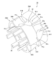
次に、図6〜図10を参照して、回転体23について詳しく説明する。図6は回転体23の斜視図であり、図7は回転体23の正面図であり、図8は回転体23の側面図であり、図9は待機流路31の下流端部にて遊技球が2個待機している状態の図であり、図10は待機流路31の下流端部にて遊技球が1個待機している状態の図である。なお、第1回転体23Aに形成される3つの球保持部を30A,30B,30C、第2回転体23Bに形成される3つの球保持部を30a,30b,30cとし、全てを総称する場合、球保持部30と称する。球保持部30は、回転体23の回転に伴って、30A、30a、30B、30b、30C、30cの順番で、待機流路31の下流端部に臨む。
Next, the rotating
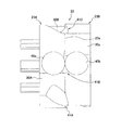
上述のように、待機流路31は、回転体23の回転軸22の軸方向の幅が少なくとも遊技球の直径の2倍以上に形成される。したがって、通常は、遊技球は、待機流路31を2条で流下し、図9に示すように、第1回転体23A及び第2回転体23Bのそれぞれの周面上に1球ずつ供給され、待機流路31の下流端部にて遊技球が2個(図9中、符号40a,40bにて示す遊技球)待機する状態となる。この場合には、回転体23の回転に伴い、待機流路31の下流端部にて待機する遊技球40a,40bは、第1回転体23A及び第2回転体23Bのそれぞれの球保持部30に交互に収容されるため、回転体23の全ての球保持部30にて遊技球が保持されることになる。
As described above, the
しかし、遊技機100は、球貯留ユニット11の誘導樋15に遊技球を2条に整流するための装置を有さないため、図10に示すように、待機流路31の下流端部にて遊技球が1個(図10中、符号40cにて示す遊技球)しか待機しない状態、つまり、直上の2個の遊技球40dと40eの間の溝に嵌り込んだ状態となる場合がある。この状態は、排出装置20に遊技球が全く無い状態で、遊技球を排出装置20へと供給開始する際に起こり易い。また、遊技球が誘導樋15から排出装置20へと導かれる過程で、前2個と後2個の遊技球の間に嵌り込んだ場合にも起こり得る。
However, since the
待機流路31の下流端部にて遊技球が1個しか待機しない状態では、その遊技球40cは、第1回転体23Aと第2回転体23Bとの境界付近で待機することとなるため、回転体23が回転し、球保持部30が待機流路31の下流端部に臨んでも、球保持部30へと収容されない場合がある。また、図10の状態では、遊技球40cは、回転体23の回転に伴い、次に待機流路31の下流端部に臨む第2回転体23Bの球保持部30aに収容されなければならいが、第2回転体23Bの球保持部30aには収容されずに、その次に待機流路31の下流端部に臨む第1回転体23Aの球保持部30Bに収容されてしまう場合がある。
In the state where only one game ball waits at the downstream end of the
このように、待機流路31の下流端部にて遊技球が1個しか待機しない状態では、その1個の遊技球40cは、収容されるべき球保持部30へと収容されない場合があり、その場合には、排出装置20は、排出要求通りの遊技球を排出できないことになる。
Thus, in a state where only one game ball is waiting at the downstream end of the
このような事態を回避するため、回転体23の周面には、待機流路31の下流端部にて待機する遊技球が1個だけの場合に、その遊技球を、次に待機流路31の下流端部に臨む球保持部30へと誘導する誘導部41が複数形成される。
In order to avoid such a situation, when there is only one game ball waiting at the downstream end of the
誘導部41は、図6及び図8に示すように、第1回転体23Aと第2回転体23Bの互いに隣合う球保持部30の間に配設され、回転体23の周方向に沿って窪んで形成される。本実施の形態では、誘導部41は、6個(41A〜41F)形成され、41A,41B,・・・41Fの順番で待機流路31の下流端部に臨む。
As shown in FIGS. 6 and 8, the
誘導部41は、第1回転体23Aと第2回転体23Bとの境界23a付近で待機する遊技球を後続の球保持部30へと誘導可能なように、第1回転体23Aと第2回転体23Bとの境界23aから後続の球保持部30に向かって形成される。また、誘導部41は、略V字状に形成され、後続の球保持部30に向かって幅広に形成される。
The guiding
誘導部41は、断面が円弧状に形成され、後続の球保持部30に対して円弧状に開口する。誘導部41の断面が円弧状に形成されることによって、誘導部41には最底部である谷部42(図6参照)が形成され、その谷部42は、第1回転体23Aと第2回転体23Bとの境界23aに対して、つまり、回転体23の回転方向に対して所定の角度差を持って延在する。
The
さらに、誘導部41は、第1回転体23Aと第2回転体23Bとの境界23aを横切って形成される。つまり、第1回転体23Aと第2回転体23Bとの周面を跨いで形成される。
Furthermore, the
これを具体的に説明すると、誘導部41は、V字状の先端部41aが境界23aに対して先行の球保持部30側へと寄った位置に設けられると共に、遊技球を排出する後端部41bが上述のように後続の球保持部30に対して開口する。このように、誘導部41は境界23aを横切って形成されるため、第1回転体23Aと第2回転体23Bとの境界23a付近で待機する遊技球は、回転体23の回転に伴って誘導部41へとスムーズに導かれ、後続の球保持部30へと誘導される。
More specifically, the
ここで、後続の球保持部30、先行の球保持部30とは、誘導部41を挟む2つの球保持部30のうち、それぞれ回転方向後方側、回転方向前方側のものを指す。
Here, the succeeding
誘導部41における先端部41aから後続の球保持部30に向かって延び、後続の球保持部30に誘導される遊技球をガイドする2つの案内縁41c,41dは、第1回転体23Aと第2回転体23Bとの境界23a付近で待機する遊技球を最短の経路で後続の球保持部30へと案内するように直線状に形成される。
Two guide edges 41c and 41d that extend from the
また、誘導部41は、後続の球保持部30に向かって下り傾斜して形成される。したがって、遊技球は、誘導部41にて誘導される際、後続の球保持部30へとスムーズに誘導される。
In addition, the
以上で説明した誘導部41について、図6及び図8に示す符号を参照して説明する。
The guiding
誘導部41Aは、先端部41aが境界23aに対して先行の球保持部30c側へと寄った位置、つまり第2回転体23Bに設けられると共に、後端部41bが第1回転体23Aに形成された後続の球保持部30Aに対して開口する。これにより、誘導部41Aは、遊技球を第1回転体23Aに形成された後続の球保持部30Aへと誘導する。
The
また、誘導部41Bは、先端部41aが境界23aに対して先行の球保持部30A側へと寄った位置、つまり第1回転体23Aに設けられると共に、後端部41bが第2回転体23Bに形成された後続の球保持部30aに対して開口する。これにより、誘導部41Bは、遊技球を第2回転体23Bに形成された後続の球保持部30aへと誘導する。
In addition, the
このように、誘導部41は、後続の球保持部30へと遊技球を誘導可能なように、1つ毎に逆向きに配設される。
In this way, the guiding
なお、第1ケース25内には光電センサ37(図4及び図5参照)が配設される。光電センサ37は、凹状に形成され、一方の突部が発光部であり、他方の突部が受光部である。第1回転体23Aには、回転軸22の周りに環状に配置された6つの遮光棒38が配設され、各遮光棒38は、回転体23の回転に伴って順次に光電センサ37の凹部を通過する。
A photoelectric sensor 37 (see FIGS. 4 and 5) is disposed in the
光電センサ37は、回転軸22の鉛直上方に配設され、また、各遮光棒38は、図7に示すように、各誘導部41A〜41Fに対応して配設される。したがって、光電センサ37は、各誘導部41A〜41Fが待機流路31の下流端部に臨んだ状態を検出することができるため、その検出信号を基に、遊技球が球保持部30に収容される直前の状態(図9の状態)で回転体23を止めることができる。これにより、回転体23の停止位置を正確に制御することができ、遊技球が余分に排出することを防止することができる。
The
次に、主に図11〜図13を参照して、誘導部41の作用について説明する。図11は待機流路31の下流端部にて遊技球が2個待機している状態の図であり、図12は待機流路31の下流端部にて遊技球が1個待機している状態の図であり、図13は遊技球が球保持部30へと流入した状態の図である。なお、図11〜図13は、回転体23を待機流路31側から見た、つまり回転体23を真上から見た図であり、遊技球は、待機流路31の下流端部に存在するもののみを示す。
Next, the operation of the guiding
まず、図11に示すように、待機流路31の下流端部に2個の遊技球40a,40bが待機する通常の場合について説明する。回転体23の回転に伴って、第2回転体23Bの周上にて待機する遊技球40bは、誘導部41Bに案内されて、次に待機流路31の下流端部に臨む第2回転体23Bの球保持部30aに収容される。また、第1回転体23Aの周上にて待機する遊技球40aは、誘導部41Cに案内されて、その次に待機流路31の下流端部に臨む第1回転体23Aの球保持部30Bに収容される。
First, as shown in FIG. 11, a normal case where two
このように、誘導部41は、待機流路31の下流端部にて待機する遊技球が2個の場合には、その待機する2個の遊技球を、それぞれが待機する回転体23の周方向に沿って案内し、球保持部30へとスムーズに誘導する。
Thus, when there are two game balls waiting at the downstream end of the
次に、図12に示すように、待機流路31の下流端部に1個の遊技球40cだけが待機し、その遊技球40cを誘導部41Bにて誘導する場合について説明する。
Next, as shown in FIG. 12, a case where only one
誘導部41Bは、境界23aを横切り後続の球保持部30aに連通して形成される。したがって、回転体23の回転に伴って、境界23a付近にて待機する遊技球40cは、誘導部41Bによって第2回転体23B側へと移動し、図13に示すように、次に待機流路31の下流端部に臨む第2回転体23Bの球保持部30aに収容される。
The
このように、誘導部41は、待機流路31の下流端部にて待機する遊技球が1個の場合には、その待機する1個の遊技球を、次に待機流路31の下流端部に臨む球保持部30へと誘導する。
As described above, when the number of game balls waiting at the downstream end of the
以上に示す実施の形態によれば、以下に示す効果を奏する。 According to the embodiment described above, the following effects can be obtained.
待機流路31の下流端部にて待機する遊技球が1個だけの場合でも、その遊技球は、誘導部41によって次に待機流路31の下流端部に臨む球保持部30へと確実に誘導されるため、第1回転体23A及び第2回転体23Bの全ての球保持部30に遊技球が収容される。このように、排出装置20は、遊技球の排出と共に、回転体23に供給される遊技球の整流も行うことができるため、遊技機100に別途整流装置を設ける必要がなく、遊技機100を簡便な構造にすることができる。
Even if there is only one game ball waiting at the downstream end of the
また、仮に、誘導部41が、回転体23の周面に隆起して形成され、その隆起した形状によって境界23a付近にて待機する1個の遊技球を誘導する場合について考える。この場合、待機する遊技球を誘導部にて誘導する際、その遊技球は隆起した誘導部によって持ち上げられて誘導される。また、その際、待機流路31にて待機する上方の遊技球も持ち上げられるため、モータ24に高負荷が作用するおそれがある。これに対して、本実施の形態では、誘導部41は、回転体23の周面に窪んで形成されるため、待機する遊技球を誘導部41にて誘導する際、その遊技球は誘導部41によって持ち上げられることはなく、モータ24に高負荷が作用することはない。したがって、境界23a付近にて待機する1個の遊技球を誘導部41によって誘導する場合でもモータ24は安定して回転すると共に、モータ24の省電力化にも寄与する。
Further, suppose that the
本発明は上記の実施の形態に限定されずに、その技術的な思想の範囲内において種々の変更がなしうることは明白である。 The present invention is not limited to the above-described embodiment, and it is obvious that various modifications can be made within the scope of the technical idea.
本発明の遊技機は、前記実施の形態に示されるようなパチンコ遊技機に限られるものではなく、例えば、その他のパチンコ遊技機、アレンジボール遊技機、雀球遊技機などの遊技球を使用する全ての遊技機に適用可能である。 The gaming machine of the present invention is not limited to the pachinko gaming machine as shown in the above embodiment, and uses, for example, gaming balls such as other pachinko gaming machines, arrange ball gaming machines, and sparrow ball gaming machines. Applicable to all gaming machines.
100 遊技機
3 裏機構盤
11 球貯留ユニット
12 球排出ユニット
13 排出制御装置
14 貯留タンク
15 誘導樋
20 排出装置
21 ケーシング
22 回転軸
23 回転体
23A 第1回転体
23B 第2回転体
23a 境界
24 モータ
25 第1ケース
26 第2ケース
27 第3ケース
28 入口部
30 球保持部
31 待機流路
32 排出流路
41 誘導部
41a 先端部
41b 後端部
41c,41d 案内縁
42 谷部
100
Claims (4)
前記排出装置は、
同一の回転軸を中心に回転可能な一対の回転体と、
前記一対の回転体に対して遊技球を2条で供給可能な待機流路と、
前記一対の回転体のそれぞれの周面に形成され、前記待機流路の下流端部にて待機する遊技球を、当該回転体の回転に伴い1個保持可能な複数の球保持部と、
前記球保持部に保持され前記回転体の回転により搬送された遊技球が排出される排出流路と、を備え、
前記一対の回転体は、回転に伴ってそれぞれの前記球保持部が交互に前記待機流路の下流端部に臨むように、互いの前記球保持部が所定の位相差を持って前記回転軸に固定され、
前記待機流路の下流端部にて待機する遊技球が1個だけの場合に、その遊技球を、次に前記待機流路の下流端部に臨む球保持部へと誘導する誘導部が前記一対の回転体の周面に形成され、
前記誘導部は、前記一対の回転体の互いに隣合う前記球保持部の間に配設され、当該一対の回転体の周方向に沿って窪んで形成されることを特徴とする遊技機。 In a gaming machine equipped with a discharge device that discharges a required number of game balls based on establishment of a predetermined discharge condition,
The discharging device is
A pair of rotating bodies rotatable around the same rotation axis;
A standby flow path capable of supplying game balls in two strips to the pair of rotating bodies;
A plurality of ball holding portions formed on respective peripheral surfaces of the pair of rotating bodies and capable of holding one game ball waiting at the downstream end of the standby flow path as the rotating body rotates;
A discharge flow path for discharging the game ball held by the rotation of the rotating body and held by the ball holding unit,
The pair of rotators are configured such that each of the sphere holding portions has a predetermined phase difference so that each of the sphere holding portions alternately faces the downstream end portion of the standby flow path with rotation. Fixed to
When there is only one game ball waiting at the downstream end of the standby flow path, the guide section for guiding the game ball to the ball holding section facing the downstream end of the standby flow path is Formed on the peripheral surfaces of the pair of rotating bodies,
The gaming machine is characterized in that the guide portion is disposed between the ball holding portions adjacent to each other of the pair of rotating bodies and is recessed along a circumferential direction of the pair of rotating bodies.
当該誘導部の先端部は、前記一対の回転体の境界に対して先行の球保持部側へと寄った位置に設けられると共に、後端部は、後続の球保持部に対して開口することを特徴とする請求項3に記載の遊技機。 The guide part is formed wide toward the subsequent sphere holding part,
The leading end portion of the guide portion is provided at a position close to the preceding ball holding portion side with respect to the boundary between the pair of rotating bodies, and the rear end portion opens to the following ball holding portion. The gaming machine according to claim 3.
Priority Applications (1)
| Application Number | Priority Date | Filing Date | Title |
|---|---|---|---|
| JP2007261042A JP4783350B2 (en) | 2007-10-04 | 2007-10-04 | Game machine |
Applications Claiming Priority (1)
| Application Number | Priority Date | Filing Date | Title |
|---|---|---|---|
| JP2007261042A JP4783350B2 (en) | 2007-10-04 | 2007-10-04 | Game machine |
Publications (2)
| Publication Number | Publication Date |
|---|---|
| JP2009089779A true JP2009089779A (en) | 2009-04-30 |
| JP4783350B2 JP4783350B2 (en) | 2011-09-28 |
Family
ID=40662378
Family Applications (1)
| Application Number | Title | Priority Date | Filing Date |
|---|---|---|---|
| JP2007261042A Expired - Fee Related JP4783350B2 (en) | 2007-10-04 | 2007-10-04 | Game machine |
Country Status (1)
| Country | Link |
|---|---|
| JP (1) | JP4783350B2 (en) |
Cited By (1)
| Publication number | Priority date | Publication date | Assignee | Title |
|---|---|---|---|---|
| JP2009089778A (en) * | 2007-10-04 | 2009-04-30 | Sophia Co Ltd | Game machine |
Citations (4)
| Publication number | Priority date | Publication date | Assignee | Title |
|---|---|---|---|---|
| JP2002172240A (en) * | 2000-09-28 | 2002-06-18 | Adachi Light Co Ltd | Ball control device for pachinko machine |
| JP2003019306A (en) * | 2000-06-14 | 2003-01-21 | Adachi Light Co Ltd | Ball controller for pachinko machine |
| JP2005304787A (en) * | 2004-04-21 | 2005-11-04 | Adachi Light Co Ltd | Pachinko ball flow separating device |
| JP2009089778A (en) * | 2007-10-04 | 2009-04-30 | Sophia Co Ltd | Game machine |
-
2007
- 2007-10-04 JP JP2007261042A patent/JP4783350B2/en not_active Expired - Fee Related
Patent Citations (4)
| Publication number | Priority date | Publication date | Assignee | Title |
|---|---|---|---|---|
| JP2003019306A (en) * | 2000-06-14 | 2003-01-21 | Adachi Light Co Ltd | Ball controller for pachinko machine |
| JP2002172240A (en) * | 2000-09-28 | 2002-06-18 | Adachi Light Co Ltd | Ball control device for pachinko machine |
| JP2005304787A (en) * | 2004-04-21 | 2005-11-04 | Adachi Light Co Ltd | Pachinko ball flow separating device |
| JP2009089778A (en) * | 2007-10-04 | 2009-04-30 | Sophia Co Ltd | Game machine |
Cited By (1)
| Publication number | Priority date | Publication date | Assignee | Title |
|---|---|---|---|---|
| JP2009089778A (en) * | 2007-10-04 | 2009-04-30 | Sophia Co Ltd | Game machine |
Also Published As
| Publication number | Publication date |
|---|---|
| JP4783350B2 (en) | 2011-09-28 |
Similar Documents
| Publication | Publication Date | Title |
|---|---|---|
| JP2014117466A (en) | Pachinko game machine | |
| JP5127172B2 (en) | Pachinko machine | |
| JP4457044B2 (en) | Game machine | |
| JP4783350B2 (en) | Game machine | |
| JP4860767B1 (en) | Amusement stand | |
| JP4783349B2 (en) | Game machine | |
| JP5744149B2 (en) | Bullet ball machine | |
| JP5927547B2 (en) | Game machine | |
| JP4677830B2 (en) | Ball dispensing device and game machine | |
| JP2011156206A (en) | Pinball game machine | |
| JP4916260B2 (en) | Pachinko machine | |
| JP5230036B2 (en) | Unitized ball payout mechanism | |
| JP2004049744A (en) | Ball dispenser | |
| JP2004089506A (en) | Inner frame structure of game machine, winning ball paying out mechanism | |
| JP6145625B2 (en) | Amusement stand | |
| JP5066048B2 (en) | Game ball screw dispenser | |
| JP6014843B2 (en) | Amusement stand | |
| JP2022040327A (en) | Game machine | |
| JP6103399B2 (en) | Amusement stand | |
| JP2006000495A (en) | Game ball pay-out device | |
| JP2022040330A (en) | Game machine | |
| JP2022040326A (en) | Game machine | |
| JP2022051917A (en) | Game machine | |
| JP2022058937A (en) | Game machine | |
| JP5630846B2 (en) | Unitized ball payout mechanism |
Legal Events
| Date | Code | Title | Description |
|---|---|---|---|
| A977 | Report on retrieval |
Free format text: JAPANESE INTERMEDIATE CODE: A971007 Effective date: 20110412 |
|
| A131 | Notification of reasons for refusal |
Free format text: JAPANESE INTERMEDIATE CODE: A131 Effective date: 20110419 |
|
| A521 | Written amendment |
Free format text: JAPANESE INTERMEDIATE CODE: A523 Effective date: 20110608 |
|
| TRDD | Decision of grant or rejection written | ||
| A01 | Written decision to grant a patent or to grant a registration (utility model) |
Free format text: JAPANESE INTERMEDIATE CODE: A01 Effective date: 20110705 |
|
| A01 | Written decision to grant a patent or to grant a registration (utility model) |
Free format text: JAPANESE INTERMEDIATE CODE: A01 |
|
| A61 | First payment of annual fees (during grant procedure) |
Free format text: JAPANESE INTERMEDIATE CODE: A61 Effective date: 20110708 |
|
| FPAY | Renewal fee payment (event date is renewal date of database) |
Free format text: PAYMENT UNTIL: 20140715 Year of fee payment: 3 |
|
| R150 | Certificate of patent or registration of utility model |
Ref document number: 4783350 Country of ref document: JP Free format text: JAPANESE INTERMEDIATE CODE: R150 Free format text: JAPANESE INTERMEDIATE CODE: R150 |
|
| FPAY | Renewal fee payment (event date is renewal date of database) |
Free format text: PAYMENT UNTIL: 20140715 Year of fee payment: 3 |
|
| R250 | Receipt of annual fees |
Free format text: JAPANESE INTERMEDIATE CODE: R250 |
|
| R250 | Receipt of annual fees |
Free format text: JAPANESE INTERMEDIATE CODE: R250 |
|
| R250 | Receipt of annual fees |
Free format text: JAPANESE INTERMEDIATE CODE: R250 |
|
| R250 | Receipt of annual fees |
Free format text: JAPANESE INTERMEDIATE CODE: R250 |
|
| R250 | Receipt of annual fees |
Free format text: JAPANESE INTERMEDIATE CODE: R250 |
|
| R250 | Receipt of annual fees |
Free format text: JAPANESE INTERMEDIATE CODE: R250 |
|
| LAPS | Cancellation because of no payment of annual fees |