JP2009088251A - Core and transformer using the same, and switching power supply - Google Patents
Core and transformer using the same, and switching power supply Download PDFInfo
- Publication number
- JP2009088251A JP2009088251A JP2007256141A JP2007256141A JP2009088251A JP 2009088251 A JP2009088251 A JP 2009088251A JP 2007256141 A JP2007256141 A JP 2007256141A JP 2007256141 A JP2007256141 A JP 2007256141A JP 2009088251 A JP2009088251 A JP 2009088251A
- Authority
- JP
- Japan
- Prior art keywords
- core
- beam portion
- upper beam
- cross
- magnetic flux
- Prior art date
- Legal status (The legal status is an assumption and is not a legal conclusion. Google has not performed a legal analysis and makes no representation as to the accuracy of the status listed.)
- Granted
Links
Images


Landscapes
- Dc-Dc Converters (AREA)
Abstract
Description
本発明はトランスに用いるコアに関し、特に、放熱特性が改善されたコアに関する。また、本発明は、このようなコアを用いたトランスに関する。また、本発明はこのようなトランスを用いたスイッチング電源装置に関する。 The present invention relates to a core used for a transformer, and more particularly to a core having improved heat dissipation characteristics. The present invention also relates to a transformer using such a core. The present invention also relates to a switching power supply device using such a transformer.
スイッチング電源装置などに用いられるトランスは、動作時において発熱することから、放熱特性の高いコアを採用することが望ましい。放熱特性の改善されたコアとしては、特許文献1に記載されたコアが知られている。
Since a transformer used in a switching power supply or the like generates heat during operation, it is desirable to employ a core having high heat dissipation characteristics. As a core with improved heat dissipation characteristics, a core described in
特許文献1に記載されたコアは、ベースプレート側に位置させる下側梁部の厚さを薄くし、その分、上側梁部の厚さを増大させた構造を有している。かかる構造により、放熱性の高い下側梁部における発熱量が増大し、放熱性の低い上側梁部における発熱量が減少することから、コアの温度分布をほぼ一定とすることが可能となるとされている。
しかしながら、上側梁部にて発生する熱は下側梁部を介してベースプレートに放熱されることから、単に上側梁部の厚さを厚くするだけでは、実際には上側梁部に熱が蓄積しやすい場合があった。このため、特に発熱量の大きいトランスにおいては、特許文献1に記載のコアよりもさらに温度特性の優れたコアを用いることが望まれる。
However, since the heat generated in the upper beam is radiated to the base plate through the lower beam, simply increasing the thickness of the upper beam actually accumulates heat in the upper beam. Sometimes it was easy. For this reason, it is desirable to use a core having superior temperature characteristics as compared with the core described in
したがって、本発明の目的は、下側梁部からの放熱効率が高められたコアを提供することである。 Accordingly, an object of the present invention is to provide a core with improved heat dissipation efficiency from the lower beam portion.
また、本発明の他の目的は、このようなコアを用いたトランスを提供することである。 Another object of the present invention is to provide a transformer using such a core.
また、本発明のさらに他の目的は、このようなトランスを用いたスイッチング電源装置を提供することである。 Still another object of the present invention is to provide a switching power supply device using such a transformer.
本発明によるコアは、巻線が巻回される主脚部と、主脚部を介して互いに対向する位置に設けられた第1梁部及び第2梁部とを含むコアであって、第1梁部の平面積をP1、第2梁部の平面積をP2、第1梁部の単位磁束当たりの断面積をS1、第2梁部の単位磁束当たりの断面積をS2とした場合、
P1>P2 且つ、
S1<S2
を満たしていることを特徴とする。
A core according to the present invention is a core including a main leg portion around which a winding is wound, and a first beam portion and a second beam portion provided at positions facing each other via the main leg portion, The plane area of one beam part is P 1 , the plane area of the second beam part is P 2 , the cross-sectional area per unit magnetic flux of the first beam part is S 1 , and the cross-sectional area per unit magnetic flux of the second beam part is S 2. If
P 1 > P 2 and
S 1 <S 2
It is characterized by satisfying.
本発明によれば、第1梁部及び第2梁部における磁束密度をそれぞれB1及びB2とすると、
B1>B2
となる。つまり、第1梁部がベースプレートなどの放熱体と直接的又は間接的に接するようにコアを載置すると、放熱性の低い第2梁部の磁束密度が低くなることから、第2梁部の発熱量を小さくすることが可能となる。しかも、第1梁部の断面積が縮小されていることから、第2梁部及び主脚部とベースプレート等の放熱体との距離が短縮され、第2梁部及び主脚部にて発生した熱をベースプレート等へ効果的に放熱することが可能となる。さらに、第1梁部の平面積が第2梁部の平面積に対して拡大されていることから、第1梁部とベースプレート等との接触面積が拡大し、放熱効率が高められる。これらにより、コア全体として高い放熱特性を得ることが可能となる。ここで、「直接的又間接的に接する」とは、第1梁部と放熱体との間に、接着剤や取り付け部材などが介在するケースを含む意である。
According to the present invention, when the magnetic flux density in the first beam portion and a second beam portion respectively B 1 and B 2,
B 1 > B 2
It becomes. That is, when the core is placed so that the first beam portion is in direct or indirect contact with the heat radiating body such as the base plate, the magnetic flux density of the second beam portion having low heat dissipation becomes low. It is possible to reduce the amount of heat generation. In addition, since the cross-sectional area of the first beam portion is reduced, the distance between the second beam portion and the main leg portion and the radiator such as the base plate is shortened, and the second beam portion and the main leg portion are generated. Heat can be effectively radiated to the base plate or the like. Furthermore, since the plane area of the first beam portion is larger than the plane area of the second beam portion, the contact area between the first beam portion and the base plate or the like is increased, and the heat radiation efficiency is improved. Accordingly, it is possible to obtain high heat dissipation characteristics as a whole core. Here, “directly or indirectly contacting” means including a case in which an adhesive, a mounting member, or the like is interposed between the first beam portion and the radiator.
本発明において、主脚部の単位磁束当たりの断面積をS3とした場合、
S1≦S3≦S2
を満たしていることが好ましい。これによれば、主脚部における磁束密度をB3とすると、
B1≧B3≧B2 且つ、
B1>B2
となる。つまり、放熱性の低い部分ほど磁束密度が低くなることから、放熱性の低い部分ほど発熱量を小さくすることが可能となる。しかも、第2梁部からの放熱ルートとなる主脚部の断面積を十分に確保していることから、ベースプレート等の放熱板上に載置した際、第2梁部にて発生した熱をベースプレート等へ効果的に放熱することが可能となる。
If in the present invention, the cross-sectional area per unit flux of main leg and a S 3,
S 1 ≦ S 3 ≦ S 2
Is preferably satisfied. According to this, when the magnetic flux density at the main leg and B 3,
B 1 ≧ B 3 ≧ B 2 and
B 1 > B 2
It becomes. That is, since the magnetic flux density is lower in the portion with lower heat dissipation, it is possible to reduce the heat generation amount in the portion with lower heat dissipation. In addition, since the cross-sectional area of the main leg portion that becomes the heat dissipation route from the second beam portion is sufficiently secured, the heat generated in the second beam portion is placed when placed on the heat sink such as the base plate. Heat can be effectively radiated to the base plate and the like.
上記の効果をより高めるためには、S1<S3を満たしていることが好ましく、S3<S2を満たしていることもまた好ましい。特に、S1<S3<S2を満たしていることが最も好ましい。 In order to further enhance the above effect, it is preferable that S 1 <S 3 is satisfied, and it is also preferable that S 3 <S 2 is satisfied. In particular, it is most preferable that S 1 <S 3 <S 2 is satisfied.
本発明において、コアは、第1梁部の略端部及び第2梁部の略端部と接する少なくとも一つの側脚部をさらに含んでおり、側脚部の単位磁束当たりの断面積をS4とした場合、
S1≦S4≦S2 且つ、
S1<S2
を満たしていることが好ましい。これによれば、側脚部の発熱を抑制することができるとともに、側脚部を介した第2梁部の放熱特性を改善することが可能となる。少なくとも一つの側脚部は、第1及び第2梁部の一端と接する第1側脚部と、第1及び第2梁部の他端と接する第2側脚部とを含んでいることが好ましい。すなわち、本発明はいわゆるEE型、EI型又は日の字型コアに適用することが好適である。
In the present invention, the core further includes at least one side leg portion in contact with the substantially end portion of the first beam portion and the substantially end portion of the second beam portion, and the cross-sectional area per unit magnetic flux of the side leg portion is S. 4
S 1 ≦ S 4 ≦ S 2 and
S 1 <S 2
Is preferably satisfied. According to this, while being able to suppress heat_generation | fever of a side leg part, it becomes possible to improve the thermal radiation characteristic of the 2nd beam part via a side leg part. The at least one side leg portion includes a first side leg portion in contact with one end of the first and second beam portions, and a second side leg portion in contact with the other end of the first and second beam portions. preferable. That is, the present invention is preferably applied to a so-called EE type, EI type, or Japanese character type core.
また、本発明によるトランスは、上記のコアと、コアの主脚部に巻回された巻線とを備えることを特徴とする。本発明によれば、放熱性の高いトランスが提供されることから、トランスが伝送する電力を増やしたり、トランスを小型化することが可能となる。 In addition, a transformer according to the present invention includes the core described above and a winding wound around a main leg portion of the core. According to the present invention, since a transformer with high heat dissipation is provided, it is possible to increase the power transmitted by the transformer or to reduce the size of the transformer.
また、本発明によるスイッチング電源装置は、上記のトランスを備えることを特徴とする。これによれば、トランスにて発生する熱が効率よく排出されることから、信頼性の高いスイッチング電源装置を提供することが可能となる。 In addition, a switching power supply device according to the present invention includes the above-described transformer. According to this, since the heat generated in the transformer is efficiently discharged, it is possible to provide a highly reliable switching power supply device.
このように、本発明によるコアは、第2梁部の発熱が低減されるとともに、第1梁部からの放熱効率が高められた構造を有していることから、第1梁部が放熱体と直接的又は間接的に接するようにコアを載置した場合、従来に比べて高い放熱特性を得ることが可能となる。 As described above, the core according to the present invention has a structure in which the heat generation of the second beam portion is reduced and the heat dissipation efficiency from the first beam portion is increased. When the core is placed so as to be in direct or indirect contact with it, it is possible to obtain higher heat dissipation characteristics than in the past.
以下、添付図面を参照しながら、本発明の好ましい実施の形態について詳細に説明する。 Hereinafter, preferred embodiments of the present invention will be described in detail with reference to the accompanying drawings.
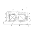
図1は、本発明の好ましい第1の実施形態によるコアの構造を示す略斜視図である。また、図2は、図1に示すコアを用いたトランスをベースプレートに載置した状態を示す模式的な断面図である。 FIG. 1 is a schematic perspective view showing the structure of a core according to a first preferred embodiment of the present invention. FIG. 2 is a schematic cross-sectional view showing a state in which a transformer using the core shown in FIG. 1 is placed on a base plate.
図1に示すように、本実施形態によるコア10は、第1梁部である下側梁部11、第2梁部である上側梁部12、主脚部13及び一対の側脚部14を有している。下側梁部11は、実装時において図2に示すベースプレート100と直接的又は間接的に接する載置面11aを有する板状体である。上側梁部12は、下側梁部11と対向する板状体である。主脚部13は、下側梁部11の中央部及び上側梁部12の中央部と接する柱状体である。側脚部14は、下側梁部11の端部及び上側梁部12の端部と接する板状体である。側脚部14は一対備えられており、下側梁部11及び上側梁部12の一端と接する第1側脚部と、下側梁部11及び上側梁部12の他端と接する第2側脚部とによって構成されている。これにより、コア10の全体形状はEE型、EI型又は日の字型である。
As shown in FIG. 1, the
本実施形態によるコア10は、下側梁部11、上側梁部12、主脚部13及び側脚部14の断面積をそれぞれSL、SU、SM、SSとした場合、
SL<SM/2=SS=SU
を満たしている。ここで「断面積」とは、図2に示すように、主脚部13に巻線19を巻回することによりトランスを構成した場合、磁束Mと直交する方向における面積を指す。主脚部13の断面積SMを2で割っているのは、図2に示すように、この部分には他の部分の2倍の磁束が形成されるからである。したがって、下側梁部11、上側梁部12、主脚部13及び側脚部14の単位磁束当たりの断面積をそれぞれS1、S2、S3、S4とすると、
S1<S2=S3=S4
となる。
In the core 10 according to the present embodiment, when the cross-sectional areas of the
S L <S M / 2 = S S = S U
Meet. Here, the “cross-sectional area” indicates an area in a direction orthogonal to the magnetic flux M when a transformer is configured by winding a winding 19 around the
S 1 <S 2 = S 3 = S 4
It becomes.
また、図1に示すように、下側梁部11の平面積PLは、上側梁部12の平面積PUよりも大きい。つまり、
PL>PU
に設定されている。ここで「平面積」とは、磁束Mと平行な方向における面積を指す。
Further, as shown in FIG. 1, the plane area P L of the
P L > P U
Is set to Here, “planar area” refers to an area in a direction parallel to the magnetic flux M.
かかる構成により、PL=PUに設定した場合と比べ、下側梁部11の厚さTLが低減されることから、上側梁部12、主脚部13及び側脚部14とベースプレート100との距離が短縮される。上側梁部12の厚さTUとの比較においては、
TL<TU
が満たされる。これにより、下側梁部11を介したベースプレート100への放熱をより効果的に行うことが可能となる。
With this configuration, since the thickness T L of the
T L <T U
Is satisfied. Thereby, it is possible to more effectively dissipate heat to the
また、図2に示すように、下側梁部11、上側梁部12、主脚部13及び側脚部14における磁束密度をそれぞれBL、BU、BM、BSとすると、本実施形態では、
BL>BM=BS=BU
となる。つまり、上側梁部12、主脚部13及び側脚部14の磁束密度が相対的に低くなることから、ベースプレート100と接することにより放熱性の高い下側梁部11と比べ、相対的に放熱性の低い部分の発熱が抑制される。しかも、主脚部13の断面積SMが上側梁部12の断面積SUの2倍に設定されていることから、上側梁部12からの放熱ルートを十分に確保することが可能となる。つまり、特許文献1に記載されたコアのように主脚部13の断面積SMが小さい場合、上側梁部12における発熱を低減させたとしても、発生した熱を放出するルートが狭いため上側梁部12に熱が溜まりやすくなる。これに対し、本実施形態によるコア10では、主脚部13の断面積SMが十分に確保されていることから、主脚部13自体の発熱が抑制されるだけでなく、上側梁部12の放熱特性を高めることが可能となる。
Further, as shown in FIG. 2, when the magnetic flux densities in the
B L > B M = B S = B U
It becomes. That is, since the magnetic flux density of the
また、本実施形態では、上側梁部12の平面積PUが下側梁部11の平面積PLよりも小さいことから、製造時において、上側梁部12を含む部分を平面的に多数個並べて焼成する際、一度に焼成できる数を増やすことができる。つまり、上側梁部12の平面積PUを下側梁部11の平面積PLと同様に拡大した場合と比べ、上側梁部12を含む部分を一度により多く作製することができることから、製造コストを削減することが可能となる。
Further, in the present embodiment, since the plane area P U of the
図3は、本発明の好ましい第2の実施形態によるコアの構造を示す略斜視図である。 FIG. 3 is a schematic perspective view showing the structure of the core according to the second preferred embodiment of the present invention.
図3に示すように、本実施形態によるコア20は、下側梁部21、上側梁部22、主脚部23及び一対の側脚部24を有しており、これらの断面積SL、SU、SM、SSが
SL=SM/2=SS<SU
を満たしている。したがって、下側梁部21、上側梁部22、主脚部23及び側脚部24の単位磁束当たりの断面積S1、S2、S3、S4は、
S1=S3=S4<S2
となる。本実施形態においても、下側梁部21の平面積PLは、上側梁部22の平面積PUよりも大きい。つまり、
PL>PU
に設定されている。このため、PL=PUに設定した場合と比べ、下側梁部21の厚さTLが低減され、
TL<TU
が満たされている。これにより、下側梁部21を介したベースプレート100への放熱をより効果的に行うことが可能となる。
As shown in FIG. 3, the core 20 according to the present embodiment includes a
Meet. Therefore, the cross-sectional areas S 1 , S 2 , S 3 , S 4 per unit magnetic flux of the
S 1 = S 3 = S 4 <S 2
It becomes. In this embodiment, the planar area P L of the
P L > P U
Is set to For this reason, compared with the case where P L = P U is set, the thickness T L of the
T L <T U
Is satisfied. Thereby, it is possible to more effectively dissipate heat to the
また、下側梁部21、上側梁部22、主脚部23及び側脚部24における磁束密度BL、BU、BM、BSは、
BL=BM=BS>BU
となる。これにより、上側梁部22の磁束密度が相対的に低くなることから、上側梁部22の発熱が抑制される。しかも、主脚部23の断面積SMが下側梁部21の断面積SLの2倍に設定されていることから、上側梁部22からの放熱ルートを十分に確保することが可能となる。
Further, the magnetic flux densities B L , B U , B M , and B S in the
B L = B M = B S > B U
It becomes. Thereby, since the magnetic flux density of the upper beam part 22 becomes relatively low, the heat generation of the upper beam part 22 is suppressed. Moreover, since the cross-sectional area S M of the
本実施形態によるコア20は、第1の実施形態によるコア10の下側梁部11及び上側梁部12の厚さTL,TUを増大させた構造と考えることができる。これにより、コア10と比べると、上側梁部22、主脚部23及び側脚部24とベースプレート100との距離が長くなるが、磁束密度が全体的に低くなる。その結果、第1の実施形態によるコア10よりも温度上昇率を低く抑えることが可能となる。
The core 20 according to the present embodiment can be considered as a structure in which the thicknesses T L and T U of the
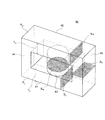
図4は、本発明の好ましい第3の実施形態によるコアの構造を示す略斜視図である。 FIG. 4 is a schematic perspective view showing the structure of a core according to a preferred third embodiment of the present invention.
図4に示すように、本実施形態によるコア30は、下側梁部31、上側梁部32、主脚部33及び一対の側脚部34を有しており、これらの断面積SL、SU、SM、SSが
SL<SM/2=SS<SU
を満たしている。したがって、下側梁部31、上側梁部32、主脚部33及び側脚部34の単位磁束当たりの断面積S1、S2、S3、S4は、
S1<S3=S4<S2
となる。本実施形態においても、下側梁部31の平面積PLは、上側梁部32の平面積PUよりも大きい。つまり、
PL>PU
に設定されている。このため、PL=PUに設定した場合と比べ、下側梁部31の厚さTLが低減され、
TL<TU
が満たされている。これにより、下側梁部31を介したベースプレート100への放熱をより効果的に行うことが可能となる。
As shown in FIG. 4, the core 30 according to the present embodiment includes a
Meet. Therefore, the cross-sectional areas S 1 , S 2 , S 3 , and S 4 per unit magnetic flux of the
S 1 <S 3 = S 4 <S 2
It becomes. In this embodiment, the planar area P L of the
P L > P U
Is set to For this reason, compared with the case where P L = P U is set, the thickness T L of the
T L <T U
Is satisfied. Thereby, it is possible to more effectively dissipate heat to the
また、下側梁部31、上側梁部32、主脚部33及び側脚部34における磁束密度BL、BU、BM、BSは、
BL>BM=BS>BU
となる。これにより、ベースプレート100から離れるほど磁束密度が低くなるという構造を得ることが可能となる。しかも、主脚部33の断面積SMが下側梁部31の断面積SLの2倍以上に設定されていることから、上側梁部32からの放熱ルートを十分に確保することが可能となる。
Further, the magnetic flux densities B L , B U , B M , and B S in the
B L > B M = B S > B U
It becomes. This makes it possible to obtain a structure in which the magnetic flux density decreases as the distance from the
本実施形態によるコア30は、第1の実施形態によるコア10の上側梁部12の厚さTUを増大させた構造と考えることができる。これにより、上側梁部32、主脚部33及び側脚部34とベースプレート100との距離をコア10と同程度としつつ、上側梁部32の磁束密度BUをさらに低くすることができる。その結果、コア10,20よりも温度上昇率を低く抑えることが可能となる。しかも、コア20よりも全体的なサイズが小さいという利点がある。
本発明によるコアを用いたトランスは、スイッチング電源装置に用いることが可能である。 The transformer using the core according to the present invention can be used for a switching power supply device.
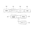
図5は、スイッチング電源装置の構成を示すブロック図である。 FIG. 5 is a block diagram showing a configuration of the switching power supply apparatus.
図5に示すスイッチング電源装置200は、直流入力電圧Vinを直流出力電圧Voutに変換するための装置(DC/DCコンバーター)であり、直流出力電圧Vinに含まれるノイズ成分を除去する入力フィルタ201と、入力フィルタ201の出力を交流に変換するスイッチング回路202と、スイッチング回路202の出力を変圧するトランス203と、トランス203の出力を直流に変換する整流回路204と、整流回路の出力を平滑化する平滑回路205とを備えている。このような構成を有するスイッチング電源装置200において、トランス203のコアとして本発明によるコアを用いれば、トランス203にて発生する熱が効率よく排出されることから、スイッチング電源装置200の信頼性を高めることが可能となる。
A switching
図5に示したスイッチング電源装置200は、特に自動車用のスイッチング電源装置として利用することが好適である。
The switching
図6は、スイッチング電源装置200を備えた自動車の主要部分を概略的に示すブロック図である。
FIG. 6 is a block diagram schematically showing a main part of an automobile provided with the switching
図6に示すように、スイッチング電源装置200を自動車用に用いた場合、スイッチング電源装置200は、高圧バッテリー210と電気機器220及び低圧バッテリー230との間に設けられ、高圧バッテリー210より供給される約144Vや約288Vの高電圧を約14Vに降圧してこれを電気機器220に供給するとともに、低圧バッテリー230を充電する役割を果たす。電気機器220としては、自動車に備えられるエアコンやオーディオ等が挙げられる。
As shown in FIG. 6, when the switching
高圧バッテリー210への充電は、発電装置240より供給される電力によって行われる。また、高圧バッテリー210の出力はモータ250にも供給され、モータ250は、高圧バッテリー210より供給される高電圧(約144Vや約288V)に基づいて駆動系260を駆動する。尚、燃料電池車においては燃料電池本体が発電装置240となり、ハイブリッド車においてはモータ250が発電装置240を兼ねることになる。
Charging the high-
以上、本発明の好ましい実施形態について説明したが、本発明は、上記の実施形態に限定されることなく、本発明の主旨を逸脱しない範囲で種々の変更が可能であり、それらも本発明の範囲内に包含されるものであることはいうまでもない。 The preferred embodiments of the present invention have been described above, but the present invention is not limited to the above-described embodiments, and various modifications can be made without departing from the spirit of the present invention. Needless to say, it is included in the range.
例えば、上記の各実施形態においては、下側梁部の断面積SL、主脚部の断面積SM、上側梁部の断面積SUとの関係が全て
SL≦SM/2≦SU
に設定されているが、本発明がこれに限定されるものではない。しかしながら、上記の関係を満たす構造とすれば、下側梁部の厚さTLをより薄くすることができることから、高い放熱特性を得ることが可能となる。
For example, in each of the above embodiments, the relationship between the cross-sectional area S L of the lower beam part, the cross-sectional area S M of the main leg part, and the cross-sectional area S U of the upper beam part is all S L ≦ S M / 2 ≦ SU
However, the present invention is not limited to this. However, if the structure satisfies the above relationship, the thickness TL of the lower beam portion can be further reduced, so that high heat dissipation characteristics can be obtained.
また、上記の各実施形態においては、主脚部の断面積SMと側脚部の断面積SSとの関係が全てSM/2=SSに設定されているが、本発明がこれに限定されるものではない。したがって、SM/2>SSに設定しても構わないし、SM/2<SSに設定しても構わない。但し、側脚部は、ベースプレートからの距離が主脚部と等しく、且つ、主脚部と同様に上側梁部からの放熱ルートとなることから、下側梁部の断面積SLと上側梁部の断面積SUとの関係においては、側脚部の断面積SSを主脚部の断面積SMの1/2と同程度に設定することが望ましい。すなわち、
SL≦SS≦SU 且つ、
SL<SU
に設定することが望ましい。
Further, in the above embodiments, although the relationship between the sectional area S S of the cross-sectional area S M and the side legs of the main leg is all set to S M / 2 = S S, the present invention this It is not limited to. Therefore, S M / 2> S S may be set, or S M / 2 <S S may be set. However, side legs, the distance from the base plate is equal to the main leg, and, since a heat radiation route from upper beam portion similarly to the main leg, the cross-sectional area S L and the upper beam of the lower beam portion In relation to the cross-sectional area S U of the part, it is desirable to set the cross-sectional area S S of the side leg part to be approximately the same as ½ of the cross-sectional area S M of the main leg part. That is,
S L ≦ S S ≦ S U and
S L <S U
It is desirable to set to.
また、主脚部は周囲が巻線に囲まれるため、側脚部よりも巻線の損失の影響が大きくなり、温度が高くなりやすい。したがって、より好ましくは、上記条件に加え、さらに
SM>SS
を満たすことで、巻線から受ける熱をより効果的にベースプレートに放熱し、コアの温度上昇を抑えることができる。
Moreover, since the periphery of the main leg is surrounded by the winding, the influence of the loss of the winding becomes larger than that of the side leg, and the temperature is likely to increase. Therefore, more preferably, in addition to the above conditions, S M > S S
By satisfying the above, it is possible to more effectively dissipate the heat received from the windings to the base plate and suppress the temperature rise of the core.
さらに、上記の各実施形態においては、1つの主脚部と2つの側脚部を有するいわゆる日の字型コア、EE型コア又はEI型コアを例に説明したが、本発明がこれに限定されるものではない。したがって、本発明をロの字型コア、UU字コア、UI字コアなどに適用することも可能である。UU字コアとはU字型のコアを2つ用いたコアであり、UI字コアとはU字型のコアとI字型のコアを用いたコアである。これらロの字型コア、UU字コア、UI字コアは、巻線が巻回される主脚部と、主脚部と略平行に配置された1つの側脚部と、主脚部及び側脚部の一端同士を接続する第1梁部と、主脚部及び側脚部の他端同士を接続する第2梁部とを有する環状体である。 Furthermore, in each of the above embodiments, a so-called Japanese-shaped core, EE core, or EI core having one main leg and two side legs has been described as an example, but the present invention is not limited thereto. Is not to be done. Therefore, the present invention can be applied to a rectangular core, UU core, UI core, and the like. The UU-shaped core is a core using two U-shaped cores, and the UI-shaped core is a core using a U-shaped core and an I-shaped core. These B-shaped cores, UU-shaped cores, and UI-shaped cores are composed of a main leg around which a winding is wound, one side leg disposed substantially parallel to the main leg, and the main leg and the side. It is an annular body having a first beam portion connecting one end of the leg portion and a second beam portion connecting the other end of the main leg portion and the side leg portion.
以下、本発明の実施例について説明するが、本発明はこの実施例に何ら限定されるものではない。 Hereinafter, although the Example of this invention is described, this invention is not limited to this Example at all.
まず、比較例サンプルとして、図7に示すコア40を想定についてシミュレータを用いて温度上昇の解析を行った。図7に示すコア40は、下側梁部41、上側梁部42、主脚部43及び一対の側脚部44を有しており、これらの断面積SL、SU、SM、SSは、図8に示すとおりに設定した。すなわち、
SL=SM/2=SS=SU
に設定されている。したがって、下側梁部41、上側梁部42、主脚部43及び側脚部44の単位磁束当たりの断面積S1、S2、S3、S4は、
S1=S2=S3=S4
である。
First, as a comparative example sample, the temperature rise was analyzed using a simulator assuming the core 40 shown in FIG. The core 40 shown in FIG. 7 has a
S L = S M / 2 = S S = S U
Is set to Therefore, the cross-sectional areas S 1 , S 2 , S 3 , and S 4 per unit magnetic flux of the
S 1 = S 2 = S 3 = S 4
It is.
また、下側梁部41の平面積PLと上側梁部42の平面積PUについても図8に示されている。このように、下側梁部41の平面積PLと上側梁部42の平面積PUが一致しており、下側梁部41の厚さTLも上側梁部42の厚さTUと一致している。
Also shown in Figure 8 for the planar area P U plane area P L and the
このようなコア40の下側梁部41をアルミニウムベースプレートに密着させて放熱特性をシミュレーションした。そして、コアの各部において磁束密度に相当する損失を与えたときの、アルミニウムベースプレートに対する温度上昇を計算した。与えた損失は、Mn−Zn系低損失フェライト材料で、同等形状のサンプルを作製して、100℃において周波数100kHz、最大磁束密度200mTの正弦波で磁束が変化したときの鉄損を測定した結果から、単位体積あたりの鉄損を計算した値を用いた。また、この測定と同時に、100kHz、100℃時に最大磁束密度を変化させて鉄損を測定し、鉄損と磁束密度との関係式を求めている。これによれば、鉄損は磁束密度の2.7乗に比例するという結果が得られている。
The
次に、図1、図3、図4に示したコア10,20,30について、上記で測定した鉄損の磁束密度特性を基に、主脚部に最大磁束密度200mTが発生した時の各部の磁束密度を計算し、鉄損に換算して各部の断面積に相当する鉄損を与えたときの温度上昇率ΔTを計算した。これらサンプルの断面積などについても図8に示した。温度上昇率ΔTは、比較例サンプルであるコア40における温度上昇を1として比率で表したものである。
Next, with respect to the
図8に示すように、コア10,20,30の温度上昇率△Tは、それぞれ0.87、0.66、0.64であり、いずれも比較例サンプルよりも温度上昇が少なかった。特に、
SL<SM/2=SS<SU
を満たしているコア30の温度上昇率△Tは、非常に小さかった。
As shown in FIG. 8, the temperature increase rates ΔT of the
S L <S M / 2 = S S <S U
The temperature increase rate ΔT of the core 30 satisfying the requirements was very small.
10,20,30,40 コア
11,21,31,41 下側梁部
11a 載置面
12,22,32,42 上側梁部
13,23,33,43 主脚部
14,24,34,44 側脚部
19 巻線
100 ベースプレート
200 スイッチング電源装置
203 トランス
B 磁束密度
M 磁束
P 平面積
S 断面積
10, 20, 30, 40
Claims (10)
前記第1梁部の平面積をP1、前記第2梁部の平面積をP2、前記第1梁部の単位磁束当たりの断面積をS1、前記第2梁部の単位磁束当たりの断面積をS2とした場合、
P1>P2 且つ、
S1<S2
を満たしていることを特徴とするコア。 A core including a main leg portion around which a winding is wound, and a first beam portion and a second beam portion provided at positions facing each other via the main leg portion,
The plane area of the first beam part is P 1 , the plane area of the second beam part is P 2 , the cross-sectional area per unit magnetic flux of the first beam part is S 1 , and the unit area magnetic flux of the second beam part is per unit magnetic flux. If the cross-sectional area was S 2,
P 1 > P 2 and
S 1 <S 2
A core characterized by satisfying
S1≦S3≦S2
を満たしていることを特徴とする請求項1に記載のコア。 If the cross-sectional area per unit flux of the main leg and the S 3,
S 1 ≦ S 3 ≦ S 2
The core according to claim 1, wherein:
S1≦S4≦S2
を満たしていることを特徴とする請求項1乃至5のいずれか一項に記載のコア。 The includes a first beam portion further substantially ends and the at least one side leg portion in contact with a substantially end portion of the second beam portion of, if the cross-sectional area per unit flux of the side legs and the S 4 ,
S 1 ≦ S 4 ≦ S 2
The core according to any one of claims 1 to 5, wherein:
Priority Applications (1)
| Application Number | Priority Date | Filing Date | Title |
|---|---|---|---|
| JP2007256141A JP4840320B2 (en) | 2007-09-28 | 2007-09-28 | Core, transformer using the same, and switching power supply device |
Applications Claiming Priority (1)
| Application Number | Priority Date | Filing Date | Title |
|---|---|---|---|
| JP2007256141A JP4840320B2 (en) | 2007-09-28 | 2007-09-28 | Core, transformer using the same, and switching power supply device |
Publications (2)
| Publication Number | Publication Date |
|---|---|
| JP2009088251A true JP2009088251A (en) | 2009-04-23 |
| JP4840320B2 JP4840320B2 (en) | 2011-12-21 |
Family
ID=40661281
Family Applications (1)
| Application Number | Title | Priority Date | Filing Date |
|---|---|---|---|
| JP2007256141A Active JP4840320B2 (en) | 2007-09-28 | 2007-09-28 | Core, transformer using the same, and switching power supply device |
Country Status (1)
| Country | Link |
|---|---|
| JP (1) | JP4840320B2 (en) |
Cited By (1)
| Publication number | Priority date | Publication date | Assignee | Title |
|---|---|---|---|---|
| CN102820125A (en) * | 2011-06-06 | 2012-12-12 | 株式会社丰田自动织机 | Magnetic core |
Citations (10)
| Publication number | Priority date | Publication date | Assignee | Title |
|---|---|---|---|---|
| JPH01176911A (en) * | 1987-12-30 | 1989-07-13 | Yokohama Rubber Co Ltd:The | Method and device for measuring external tire diameter in uniformity machine |
| JPH02129716A (en) * | 1988-11-10 | 1990-05-17 | Nec Corp | Input device |
| JPH04209509A (en) * | 1990-12-04 | 1992-07-30 | Mitsubishi Electric Corp | Transformer for metal-based board |
| JPH0837113A (en) * | 1994-07-25 | 1996-02-06 | Nemic Lambda Kk | Core |
| JPH09186024A (en) * | 1995-12-28 | 1997-07-15 | Hitachi Ferrite Denshi Kk | Transformer for back light |
| JPH09213534A (en) * | 1996-01-30 | 1997-08-15 | Matsushita Electric Works Ltd | Coil device |
| JPH10189351A (en) * | 1996-12-24 | 1998-07-21 | Toyota Autom Loom Works Ltd | Insulated transformer |
| JPH11102819A (en) * | 1997-09-25 | 1999-04-13 | Tdk Corp | Magnetic core |
| JP2001015350A (en) * | 1999-04-27 | 2001-01-19 | Tdk Corp | Coil device |
| JP2002203726A (en) * | 2001-01-05 | 2002-07-19 | Toyota Industries Corp | Magnetic core |
-
2007
- 2007-09-28 JP JP2007256141A patent/JP4840320B2/en active Active
Patent Citations (10)
| Publication number | Priority date | Publication date | Assignee | Title |
|---|---|---|---|---|
| JPH01176911A (en) * | 1987-12-30 | 1989-07-13 | Yokohama Rubber Co Ltd:The | Method and device for measuring external tire diameter in uniformity machine |
| JPH02129716A (en) * | 1988-11-10 | 1990-05-17 | Nec Corp | Input device |
| JPH04209509A (en) * | 1990-12-04 | 1992-07-30 | Mitsubishi Electric Corp | Transformer for metal-based board |
| JPH0837113A (en) * | 1994-07-25 | 1996-02-06 | Nemic Lambda Kk | Core |
| JPH09186024A (en) * | 1995-12-28 | 1997-07-15 | Hitachi Ferrite Denshi Kk | Transformer for back light |
| JPH09213534A (en) * | 1996-01-30 | 1997-08-15 | Matsushita Electric Works Ltd | Coil device |
| JPH10189351A (en) * | 1996-12-24 | 1998-07-21 | Toyota Autom Loom Works Ltd | Insulated transformer |
| JPH11102819A (en) * | 1997-09-25 | 1999-04-13 | Tdk Corp | Magnetic core |
| JP2001015350A (en) * | 1999-04-27 | 2001-01-19 | Tdk Corp | Coil device |
| JP2002203726A (en) * | 2001-01-05 | 2002-07-19 | Toyota Industries Corp | Magnetic core |
Cited By (3)
| Publication number | Priority date | Publication date | Assignee | Title |
|---|---|---|---|---|
| CN102820125A (en) * | 2011-06-06 | 2012-12-12 | 株式会社丰田自动织机 | Magnetic core |
| JP2012253264A (en) * | 2011-06-06 | 2012-12-20 | Toyota Industries Corp | Magnetic core |
| US9041500B2 (en) | 2011-06-06 | 2015-05-26 | Kabushiki Kaisha Toyota Jidoshokki | Magnetic core |
Also Published As
| Publication number | Publication date |
|---|---|
| JP4840320B2 (en) | 2011-12-21 |
Similar Documents
| Publication | Publication Date | Title |
|---|---|---|
| JP5881015B2 (en) | Reactor, converter, and power converter | |
| JP6400663B2 (en) | Contactless power transformer | |
| KR101610493B1 (en) | Device for cooling transformer | |
| JP5958877B2 (en) | Reactor, converter, and power converter | |
| JP6127365B2 (en) | Reactor, composite material, reactor core, converter, and power converter | |
| JP2012156461A (en) | Electronic apparatus | |
| JP2015230904A (en) | Reactor | |
| US9041500B2 (en) | Magnetic core | |
| JP4840319B2 (en) | Core, transformer using the same, and switching power supply device | |
| JP2013179186A (en) | Reactor, component for reactor, converter, and power conversion device | |
| JP2016025137A (en) | Reactor device | |
| JP4840320B2 (en) | Core, transformer using the same, and switching power supply device | |
| JP6064943B2 (en) | Electronics | |
| JP2014150171A (en) | Reactor, converter, and electric power conversion device | |
| JP2007287956A (en) | Reactor | |
| JP4882804B2 (en) | Reactor and air conditioner | |
| JP6379353B2 (en) | DC-DC converter | |
| JP2018082129A (en) | Reactor | |
| JP2015012145A (en) | Reactor | |
| JP2018006650A (en) | Reactor | |
| JP2009111316A (en) | Reactor | |
| JP2017224715A (en) | Reactor structure | |
| JP2014067907A (en) | Core, coil component using the same, and switching power supply device | |
| JP2015188019A (en) | Gap member, magnetic core and reactor | |
| WO2021144945A1 (en) | In-vehicle charger |
Legal Events
| Date | Code | Title | Description |
|---|---|---|---|
| A131 | Notification of reasons for refusal |
Free format text: JAPANESE INTERMEDIATE CODE: A131 Effective date: 20101102 |
|
| A521 | Written amendment |
Free format text: JAPANESE INTERMEDIATE CODE: A523 Effective date: 20101228 |
|
| TRDD | Decision of grant or rejection written | ||
| A01 | Written decision to grant a patent or to grant a registration (utility model) |
Free format text: JAPANESE INTERMEDIATE CODE: A01 Effective date: 20110906 |
|
| A01 | Written decision to grant a patent or to grant a registration (utility model) |
Free format text: JAPANESE INTERMEDIATE CODE: A01 |
|
| A61 | First payment of annual fees (during grant procedure) |
Free format text: JAPANESE INTERMEDIATE CODE: A61 Effective date: 20110919 |
|
| R150 | Certificate of patent or registration of utility model |
Ref document number: 4840320 Country of ref document: JP Free format text: JAPANESE INTERMEDIATE CODE: R150 Free format text: JAPANESE INTERMEDIATE CODE: R150 |
|
| FPAY | Renewal fee payment (event date is renewal date of database) |
Free format text: PAYMENT UNTIL: 20141014 Year of fee payment: 3 |