JP2009086584A - Optical device - Google Patents
Optical device Download PDFInfo
- Publication number
- JP2009086584A JP2009086584A JP2007259675A JP2007259675A JP2009086584A JP 2009086584 A JP2009086584 A JP 2009086584A JP 2007259675 A JP2007259675 A JP 2007259675A JP 2007259675 A JP2007259675 A JP 2007259675A JP 2009086584 A JP2009086584 A JP 2009086584A
- Authority
- JP
- Japan
- Prior art keywords
- voltage
- optical
- cpu
- optical device
- optical system
- Prior art date
- Legal status (The legal status is an assumption and is not a legal conclusion. Google has not performed a legal analysis and makes no representation as to the accuracy of the status listed.)
- Pending
Links
Images


Landscapes
- Viewfinders (AREA)
- Liquid Crystal (AREA)
- Camera Bodies And Camera Details Or Accessories (AREA)
- Automatic Focus Adjustment (AREA)
Abstract
Description
本発明は、光学装置に関する。 The present invention relates to an optical device.
電圧に応じて焦点距離を変化させる光学素子を用いて、カメラなどのファインダー視度を調節する技術が知られている(特許文献1参照)。特許文献2には、温度に応じた光学素子の制御を行う技術が開示されている。 A technique for adjusting a finder diopter of a camera or the like using an optical element that changes a focal length according to a voltage is known (see Patent Document 1). Patent Document 2 discloses a technique for controlling an optical element according to temperature.
従来技術では、メインスイッチがオフされると光学素子が機能しなくなってしまい、光学像が得られないという問題があった。 The prior art has a problem that when the main switch is turned off, the optical element does not function and an optical image cannot be obtained.
(1)本発明は以下のような解決手段により上述の問題を解決する。ここでは理解を容易ににするために本発明の実施形態に対応する符号を付して説明するが、本発明の各構成要件は、この符号の実施形態に限定されるものではない。本発明による光学装置(1)は、外部操作可能であり、そのオン操作により装置内に給電せしめ、そのオフ操作により該給電を停止せしめるメインスイッチ(4)と、電圧に応じて焦点距離を変化させる光学素子を有する光学系(310)と、メインスイッチの操作状態にかかわらず光学素子へ電圧を供給する電圧供給手段(501,16)とを備えることを特徴とする。
(2)請求項1に記載の光学装置において、光学系は、光学装置に対して着脱自在に構成されていてもよい。
(3)請求項2に記載の光学装置はさらに、光学系が装着されているか否かを判定する判定手段を備えてもよい。この場合の電圧供給手段は、判定手段が否定判定した場合は電圧供給を停止することが好ましい。
(4)請求項1〜3のいずれか一項に記載の光学装置はさらに、装填されている電池の電圧を検出する電圧検出手段を備えてもよい。この場合の電圧供給手段は、電圧検出手段による検出電圧が所定値未満の場合は電圧供給を停止することが好ましい。
(5)請求項1〜4のいずれか一項に記載の光学装置において、電圧供給手段は、メインスイッチがオフ操作された状態のときに光学素子へ所定電圧を供給することもできる。
(6)請求項5に記載の光学装置において、所定電圧は、メインスイッチがオフ操作される直前に光学素子へ供給されていた電圧であることが好ましい。
(7)請求項5に記載の光学装置において、所定電圧は、所定の焦点距離に対応する電圧であることが好ましい。
(8)請求項5〜7のいずれか一項に記載の光学装置はさらに、光学素子および/またはその近傍の環境情報を検出する環境情報検出手段を備えてもよい。この場合の電圧供給手段は、環境情報検出手段で検出された環境情報に応じてメインスイッチのオフ操作後に供給する電圧を補正することが好ましい。
(9)請求項8に記載の光学装置において、環境情報検出手段は所定時間ごとに環境情報を検出し、電圧供給手段は、環境情報検出手段で検出された最新の環境情報に応じて供給する電圧を制御することもできる。
(10)請求項9に記載の光学装置において、環境情報は温度を含み、電圧供給手段は、温度に応じて供給する電圧を制御することもできる。
(11)請求項1〜10のいずれか一項に記載の光学装置において、光学素子は、第1液体材料と、該第1液体材料と屈折率が異なり、かつ該第1液体材料と混合しない第2液体材料とが容器内に封入され、供給電圧に応じて第1液体材料および第2液体材料の境界面形状を変化させることによって焦点距離を変化させることもできる。
(12)請求項1〜11のいずれか一項に記載の光学装置において、光学装置は撮影を行うカメラであってもよく、光学系は撮影光学系を含めてもよい。
(13)請求項12に記載の光学装置において、撮影光学系は、供給電圧に応じてフォーカス調節を行うこともできる。
(14)請求項1〜13のいずれか一項に記載の光学装置において、光学系は観察光学系を含めてもよい。
(15)請求項14に記載の光学装置において、観察光学系は、供給電圧に応じて視度調節を行うこともできる。
(1) The present invention solves the above problems by the following means. Here, in order to facilitate understanding, description will be given with reference numerals corresponding to the embodiments of the present invention, but each component of the present invention is not limited to the embodiments of the reference numerals. The optical device (1) according to the present invention can be externally operated, and the main switch (4) that feeds power into the device by its on operation and stops the power feeding by its off operation, and the focal length changes according to the voltage An optical system (310) having an optical element to be operated and voltage supply means (501, 16) for supplying a voltage to the optical element regardless of the operation state of the main switch.
(2) In the optical device according to
(3) The optical apparatus according to claim 2 may further include a determination unit that determines whether or not the optical system is mounted. In this case, the voltage supply means preferably stops the voltage supply when the determination means makes a negative determination.
(4) The optical device according to any one of
(5) In the optical device according to any one of
(6) In the optical device according to
(7) In the optical device according to
(8) The optical device according to any one of
(9) In the optical device according to the eighth aspect, the environmental information detecting means detects environmental information every predetermined time, and the voltage supply means supplies according to the latest environmental information detected by the environmental information detecting means. The voltage can also be controlled.
(10) In the optical device according to the ninth aspect, the environmental information includes a temperature, and the voltage supply means can also control a voltage to be supplied according to the temperature.
(11) In the optical device according to any one of
(12) In the optical device according to any one of
(13) In the optical device according to the twelfth aspect, the photographing optical system can also perform focus adjustment according to the supply voltage.
(14) In the optical device according to any one of
(15) In the optical device according to the fourteenth aspect, the observation optical system can also adjust the diopter according to the supply voltage.
本発明による光学装置では、メインスイッチオフ状態でも、供給電圧に応じて焦点距離を変化させる光学素子による光学像が得られる。 In the optical device according to the present invention, even when the main switch is off, an optical image can be obtained by the optical element that changes the focal length according to the supply voltage.
以下、図面を参照して本発明を実施するための最良の形態について説明する。
(第一の実施形態)
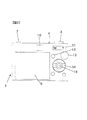
図1は、本発明の第一の実施形態による電子カメラの正面図である。図1において電子カメラ1は、レリーズスイッチ3と、メインスイッチ4と、ファインダー対物窓5と、フラッシュ発光窓6と、アンテナ7と、レンズ鏡筒8とを有する。なお、レンズ鏡筒8は、カメラ1に着脱不能に固設されているものであり、換言すれば、カメラ1はレンズ一体型カメラである。
The best mode for carrying out the present invention will be described below with reference to the drawings.
(First embodiment)
FIG. 1 is a front view of an electronic camera according to a first embodiment of the present invention. In FIG. 1, the
図2は、図1の電子カメラ1の背面図である。図2において電子カメラ1は、表示部9と、ファインダー接眼窓10と、ズームスイッチ11と、メニュースイッチ12と、モードダイヤル13と、十字キー14と、決定スイッチ15とを有する。
FIG. 2 is a rear view of the
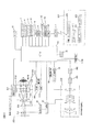
図3は、電子カメラ1の要部構成を例示するブロック図である。CPU16は、後述する各ブロックから出力される信号を入力して所定の演算を行い、演算結果に基づく制御信号を各ブロックへ出力する。CPU16が実行するプログラムは、CPU16内の不揮発性メモリ(不図示)に格納されている。
FIG. 3 is a block diagram illustrating the main configuration of the
撮影光学系400はレンズ鏡筒8内に構成され、被写体像を撮像素子401の撮像面上に結像させる。撮像素子401は、CCDイメージセンサなどによって構成される。撮像素子401は、撮像面上の被写体像を撮像して撮像信号を出力する。A/D変換回路402は、不図示の信号処理回路によってアナログ処理(ゲインコントロールなど)された後の撮像信号をディジタル信号に変換する。
The imaging
CPU16は画像処理部を含み、ディジタル変換後の画像データにホワイトバランス処理などの画像処理を行う他、画像処理後の画像データを所定の形式で圧縮する圧縮処理、圧縮された画像データを伸長する伸長処理などを行う。メモリ17はCPU16による作業用メモリとして使用される他、表示部9に表示されるデータを格納する表示用メモリ(VRAM)として使用される。また、CPU16は、CFカードやSDカードのような外部メモリ17Bに画像データの書き込み(保存処理)を行ったりする。
The
焦点検出部20は、測距素子(不図示)による検出信号を用いて撮影光学系400による焦点調節状態を検出し、検出結果に応じて撮影光学系400を構成するフォーカスレンズの移動量を算出する。なお、測距素子を用いずに、撮像素子401による撮像データからコントラストを検出する方式によって、合焦するフォーカスレンズ位置を求めるように構成してもよい。フォーカスレンズの移動量を示す信号は、CPU16を介してフォーカス駆動部19へ送出される。フォーカス駆動部19は、フォーカスレンズを光軸方向に進退移動させてフォーカス調節を行う。
The
ズーム駆動部21は、CPU16からの指示に応じて撮影光学系400を構成するズームレンズを光軸方向に進退移動させて倍率を変更する。連動ギヤ部22は、撮影光学系400の倍率変更と同期させて観察光学系(ファインダー)300の倍率を変更する。
The
観察光学系300はレンズ群301、レンズ群302、レンズ群303、視野枠304、および可変焦点部材310を含む接眼レンズ群312を有する。電子カメラ1のユーザは、ファインダー接眼窓10(図2)を介して被写体を観察する。上述した連動ギヤ部22によってレンズ群301およびレンズ群302が光軸方向に進退移動されると、観察光学系300の倍率が変更される。
The observation
可変焦点部材310は、いわゆる液体レンズによって構成される。この液体レンズ310は、互いに異なる屈折率を有するものであり、かつ互いに混合することのない2種類の液体310A、310Bが容器内に封入されたものである。この液体レンズ310に電圧を加えると、その印加される電圧に応じて2種類の液体の境界面形状が変化する。この変化により焦点距離が変化する。なお、液体の一実施形態としては、一方の液体を導電性の塩化リチウム水溶液を使用し、他方の液体310Bとして絶縁性のシリコンオイルを使用する。本実施形態では、両液体310A、310Bは同じ密度をもつものを使用するが、本発明はこれに限定するものではない。また、液体310A、310Bの順序(光軸方向における配列順序)もこれに限られるものではない。このような構成で、可変焦点部材310は、給電部501から印加される電圧に応じて焦点距離を変え、観察光学系300の視度を調節する。
The
給電部501は可変DC/DC変換回路を含み、CPU16からの指示に応じた電圧を可変焦点部材310へ印加する。電源502は電池によって構成され、給電部501およびCPU16を含むカメラ内各部へ電力を供給する。電圧計503は、電源502の電池電圧、給電部501の出力電圧をそれぞれ検出し、電圧検出信号をCPU16へ送出する。温度センサ311は、可変焦点部材310の温度を検出し、温度検出信号をCPU16へ送出する。なお、温度センサ311を可変焦点部材310に密着するように配設してもよいし、温度センサ311を可変焦点部材310の近傍に配設し、可変焦点部材310の周囲温度を検出する構成としてもよい。マイク18は、入力された音声を電気信号に変換してCPU16へ送出する。
The
レリーズスイッチ3、メインスイッチ4、ズームスイッチ11、モードダイヤル13、十字キー14、メニュースイッチ12、および決定スイッチ15は操作部材を構成する。各スイッチおよびダイヤルは、それぞれの設定操作に応じた操作信号を発生してCPU16へ送出する。表示部9はカラー液晶表示パネルによって構成され、CPU16からの指示に応じて撮影画像や操作メニュー(撮影機能や撮影条件などの設定/変更を行うための操作メニュー)、電子カメラ1に設定されている情報などを表示する。
The
アンテナ7に電気的に接続している通信部23は、CPU16からの指示によって電子カメラ1と無線接続されている外部機器200との間で通信を行う。電子カメラ1および外部機器200間の通信では、たとえば外部データサーバー251側のデータベース252に登録されているメンテナンス情報やデータ等が電子カメラ1へ送信される一方、カメラID情報やメンテナンス情報等が電子カメラ1から外部データサーバー251へ送信される。アンテナ7は無線通信の送受信に使用される。無線LANアクセスポイント201、インターネット210、外部データサーバー251、およびデータベース252は外部機器200を構成する。
The
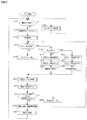
本実施形態の電子カメラ1は、観察光学系(ファインダー)300の視度調節に特徴を有するので、この点を中心に図4〜図8のフローチャートを参照して説明する。図4は、電子カメラ1のCPU16が実行するメイン処理の流れを説明するフローチャートである。CPU16は、電池502が電源として電子カメラ1に装填されると図4の処理を起動する。
The
<メイン処理>
図4のステップS11において、CPU16は電源オン操作されたか否かを判定する。CPU16は、メインスイッチ4からオン操作信号が入力された場合、または無操作タイムアップ中に各操作スイッチもしくは操作ボタン操作を示す信号が入力された場合(メインスイッチ4からのオフ操作信号を除く)にステップS11を肯定判定してステップS12へ進み、所定の電源オン処理を行う。電源オン処理は、電源502からカメラ内各部へ給電を開始させる指示を含む。CPU16は、メインスイッチ4からオン操作信号が入力されない場合、および無操作タイムアップ中に各操作スイッチもしくは操作ボタン操作を示す信号が入力されない場合にはステップS11を否定判定し、ステップS29へ進む。CPU16は、ステップS29の処理を実行後にステップS11へ戻る。
<Main processing>
In step S11 of FIG. 4, the
ステップS12において、CPU16は、無操作タイマーをリセットおよびスタートさせてステップS13へ進む。これにより、電子カメラ1に対する操作が行われない状態で所定時間(たとえば30秒)を計時すると、CPU16の内蔵タイマーがタイムアップ信号を発する。
In step S12, the
ステップS13において、CPU16は初期設定処理を行ってステップS14へ進む。初期設定処理の詳細については後述する。ステップS14において、CPU16はメニュー操作が選択されたか否かを判定する。CPU16は、メニュースイッチ12の押下操作を示す信号が入力されるとステップS14を肯定判定し、ステップS15のメニューモードへ進む。CPU16は、メニュースイッチ12の押下を示す操作信号が入力されない場合にはステップS14を否定判定し、ステップS16へ進む。
In step S13, the
ステップS15において、CPU16はセットアップメニュー表示処理を行ってステップS23へ進む。セットアップメニュー表示処理では、撮影機能や撮影条件などの設定/変更を行うための操作画面を表示部9に表示させる。CPU16は、ユーザが操作画面を見ながら操作した十字キー14などからの操作信号を受け付けることにより、各項目の設定や変更を行う。設定/変更項目には、ファインダー300の視度調節も含まれている。CPU16は、十字キー14からの操作信号に応じて給電部501へ指示を送り、可変焦点部材310へ印加する電圧を変化させてファインダー300の視度調節を行う。
In step S15, the
ステップS23において、CPU16は温度フィードバック処理を行ってステップS24へ進む。温度フィードバック処理の詳細については後述する。ステップS24において、CPU16は、電源オフ操作の受付を許可してステップS25へ進む。電子カメラ1は、各モード(メニューモード、撮影モード、および再生モード)における動作開始後は、電源オフ操作受付可を実行してから電源オフ操作を受付けるように構成されている。
In step S23, the
ステップS25において、CPU16は、電源オフ(メインスイッチオフ)操作されたか、または無操作タイムアップしたか否かを判定する。CPU16は、メインスイッチ4からオフ操作信号が入力された場合、または無操作タイマーがタイムアップ信号を発した場合はステップS25を肯定判定してステップS26へ進む。CPU16は、各操作スイッチもしくは操作ボタン操作を示す信号が入力された場合(メインスイッチ4からのオフ操作信号を除く)は、ステップS25を否定判定してステップS28へ進む。ステップS28において、CPU16は、無操作タイマーをリセットしてステップS14へ戻る。
In step S25, the
ステップS26において、CPU16は後述する視度情報(x)、電圧情報(V)および温度情報(t)をCPU16内の不揮発性メモリ(不図示)へそれぞれ記憶させてステップS27へ進む。視度情報は、観察光学系(ファインダー)300に設定されている視度値を示す。電圧情報は、所望の視度値に視度調節するために必要な電圧値であり、可変焦点部材310に印加する電圧値を示す。温度情報は、温度センサ311で検出された可変焦点部材310の温度を示す。ステップS27において、CPU16は電源オフ処理を行ってステップS11へ戻る。電源オフ処理の詳細については後述する。
In step S26, the
ステップS14を否定判定して進むステップS16において、CPU16は再生指示されたか否かを判定する。CPU16は、モードダイヤル13から、撮影済みの画像を表示部9上に、あるいは外部接続されているモニタ上に再生表示を行う再生モードへの切換設定を示す操作信号が入力されている場合にステップS16を肯定判定し、ステップS20の再生モードへ進む。CPU16は、モードダイヤル13から、被写体を撮影して外部メモリ17Bに記録する撮影モードへの切換設定を示す操作信号が入力されている場合にステップS16を否定判定し、ステップS17の撮影モードへ進む。
In step S16, which proceeds after making a negative determination in step S14, the
ステップS17において、CPU16は、撮影モード初期値設定を行ってステップS18へ進む。具体的には、撮影処理に必要なフラグやパラメータ類をセットする。ステップS18において、CPU16は撮影モード選択の受付を許可してステップS19へ進む。これにより、電子カメラ1は撮影モードに切替わる。ステップS19において、CPU16は、撮影操作の受付を許可してステップS23へ進む。これにより、CPU16は、撮影が指示(レリーズスイッチ3から操作信号が入力)されると所定の撮影処理を実行する。
In step S17, the
ステップS20において、CPU16は、再生モード初期値設定を行ってステップS21へ進む。具体的には、再生処理に必要なフラグやパラメータ類をセットする。ステップS21において、CPU16は再生モード選択の受付を許可してステップS22へ進む。これにより、電子カメラ1は再生モードに切替わる。ステップS22において、CPU16は、再生操作の受付を許可してステップS23へ進む。これにより、CPU16は、再生が指示されると所定の再生処理を実行する。
In step S20, the
<メインスイッチオフ時処理>
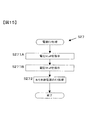
図5は、前述の図4のステップS29におけるメインスイッチオフ時処理の詳細を説明するフローチャートである。メインスイッチオフ時処理は、メインスイッチ4がオフ操作されている場合、またはメインスイッチ4がオン操作されている状態で無操作タイムアップした場合にそれぞれ実行される。図5のステップS291において、CPU16は電源電圧が所定値VS以上か否かを判定する。CPU16は、電源502の電池電圧が所定値VS以上の場合にステップS291を肯定判定し、ステップS292へ進む。CPU16は、電源502の電池電圧が所定値VS未満の場合(電池残量が少ない場合)にはステップS291を否定判定し、ステップS295へ進む。
<Process when main switch is off>
FIG. 5 is a flowchart for explaining the details of the main switch-off process in step S29 of FIG. The main switch-off process is executed when the
ステップS292において、CPU16はファインダー給電部が起動済みか否かを判定する。CPU16は、電源502が給電部501へ給電中である場合にステップS292を肯定判定してステップS294へ進み、給電部501へ給電していない場合はステップS292を否定判定してステップS293へ進む。ステップS293において、CPU16は、ファインダー給電部を起動させてステップS294へ進む。具体的には、電源502へ指示を送り、給電部501に対して給電を開始させる。
In step S292, the
ステップS294において、CPU16は、可変焦点部材310(光学素子)へ印加する電圧Voffを給電部501に指示して図5による処理を終了する。電圧Voffは、電源オフ処理(ステップS27)の直前のステップS26(図4)において電圧情報(V)としてCPU16の不揮発性メモリに記憶された電圧値である。これにより、メインスイッチオフ時(または無操作タイムアップ状態)のファインダー300の視度は、電源オフ処理直前に設定されていた状態が維持される。
In step S294, the
ステップS291を否定判定して進むステップS295において、CPU16は、可変焦点部材310(光学素子)に対する電圧の印加停止を給電部501に指示して図5による処理を終了する。これにより、電源502の電池電圧が所定値VS未満の場合は節電のために可変焦点部材310への電圧印加を行わないように制御できる。
In step S295, which proceeds after making a negative determination in step S291, the
<初期設定処理>
図6は、前述の図4のステップS13における初期設定処理の詳細を説明するフローチャートである。図6のステップS131において、CPU16は電子カメラ1の本体各部の初期設定を行ってステップS132へ進む。ステップS132において、CPU16は可変焦点部材310の温度計測を行う。具体的には、温度センサ311から温度検出信号を入力してステップS133へ進む。
<Initial setting process>
FIG. 6 is a flowchart for explaining the details of the initial setting process in step S13 of FIG. In step S131 of FIG. 6, the
ステップS133において、CPU16は、不揮発性メモリに記憶されている視度情報(x)に応じた焦点距離を再現するように可変焦点部材310に対する印加電圧を決定する。具体的には、ステップS132で計測した温度情報と、不揮発性メモリに記憶されている温度情報(t)とに基づいて電圧Voffを増減し、これらの温度差によって生じる可変焦点部材310の焦点距離の変動を抑制して不揮発性メモリに記憶されている視度情報(x)を得るために必要な印加電圧を求める。ここで、温度情報(t)および視度情報(x)は、ステップS26(図4)において不揮発性メモリに記憶されたものである。
In step S133, the
ステップS134において、CPU16は、上記決定電圧を給電部501に指示してステップS135へ進む。これにより、可変焦点部材310(光学素子)への給電電圧が制御される。ステップS135において、CPU16は視度情報(x)および電圧情報(V)をCPU16内の不揮発性メモリ(不図示)へそれぞれ記憶させて図6による処理を終了する。
In step S134, the
<温度フィードバック処理>
図7は、図4のステップS23における温度フィードバック処理の詳細を説明するフローチャートである。図7のステップS231において、CPU16は所定間隔で可変焦点部材310の温度計測を行う。具体的には、たとえば5分間隔で温度センサ311から温度検出信号を入力し、直近の検出信号を採用してステップS232へ進む。
<Temperature feedback processing>
FIG. 7 is a flowchart illustrating details of the temperature feedback process in step S23 of FIG. In step S231 in FIG. 7, the
ステップS232において、CPU16は観察光学系300に設定されている視度を維持するように可変焦点部材310に対する印加電圧を決定する。具体的には、ステップS231で計測した温度情報と初期設定時の温度情報とに所定値(たとえば5℃)以上の温度差がある場合、この温度差によって生じる可変焦点部材310の焦点距離の変動を抑制するように可変焦点部材310へ印加する電圧値を求める。
In step S232, the
ステップS233において、CPU16は、上記決定電圧を給電部501に指示してステップS234へ進む。これにより、ステップS234において可変焦点部材310(光学素子)への給電電圧が制御される。ステップS235において、CPU16は視度情報(x)および電圧情報(V)をCPU16内の不揮発性メモリ(不図示)へそれぞれ記憶させて図7による処理を終了する。図7によれば、温度変動に応じて印加電圧が微調整される。
In step S233, the
<電源オフ処理>
図8は、図4のステップS27における電源オフ処理の詳細を説明するフローチャートである。図8のステップS271において、CPU16は、可変焦点部材310(光学素子)へ印加する電圧Voffを給電部501に指示してステップS272へ進む。電圧Voffは、直前のステップS26(図4)において電圧情報(V)としてCPU16の不揮発性メモリに記憶された電圧値である。これにより、ファインダー300の視度は、電源オフ処理直前に設定されていた状態が維持される。
<Power off process>
FIG. 8 is a flowchart illustrating details of the power-off process in step S27 of FIG. In step S271 of FIG. 8, the
ステップS272において、CPU16は、カメラ本体電源のオフ処理を行って図8による処理を終了する。電源オフ処理では、給電部501を除くカメラ内各部への給電を停止するように電源502へ指示を送る。
In step S272, the
以上説明した第一の実施形態によれば、次の作用効果が得られる。
(1)印加電圧に応じて焦点距離を変える可変焦点部材310(液体レンズ)を観察光学系300に備え、メインスイッチがオン操作されている場合はもちろん、メインスイッチオフ時(または無操作タイムアップ状態)にも可変焦点部材310に電圧印加を行うようにした(図5)。これにより、メインスイッチオフ状態(または無操作タイムアップ状態)にも観察光学系300による光学像を観察できる。
According to the first embodiment described above, the following operational effects can be obtained.
(1) The observation
(2)メインスイッチオフ時(または無操作タイムアップ状態)に可変焦点部材310に印加する電圧を、電源オフ処理直前の印加電圧Voffにしたので、電源オフ処理の前後でファインダー300の視度が同じ値に維持され、光学像を観察中のユーザに違和感を与えることがない。
(2) Since the voltage applied to the
(3)メインスイッチオフ時(または無操作タイムアップ状態)において、電源の電池電圧が所定値VS未満の場合は可変焦点部材310への電圧印加を停止するようにしたので、電池残量が少ない状態では電池の過放電を防止できる。
(3) When the battery voltage of the power source is less than the predetermined value VS when the main switch is off (or when the operation time is up), the voltage application to the
(4)可変焦点部材310(液体レンズ)の温度情報を検出し、この温度情報を用いて可変焦点部材310に印加する電圧を増減するようにした(図7)。このような環境フィードバック処理を施すことにより、液体レンズのパワーが温度依存性を有する場合には検出温度に応じてパワーを補正し、電子カメラ1を使用する温度にかかわらず、ファインダー視度の変動を抑えることができる。
(4) Temperature information of the variable focus member 310 (liquid lens) is detected, and the voltage applied to the
(5)CPU16内の不揮発性メモリ(不図示)へ記憶する情報として温度情報を含めるようにしたので、情報記憶時と異なる温度環境においても、情報記憶時と同じファインダー(観察光学系300)の視度を再現できる。
(5) Since temperature information is included as information stored in a non-volatile memory (not shown) in the
(変形例1)
第一の実施形態では、ステップS271(図8)およびステップS294(図5)においてそれぞれ、電源オフ処理(ステップS27(図4))の直前に可変焦点部材310(光学素子)へ印加していた電圧Voffを給電部501に指示する例を説明した。この代わりに、所定の視度値(たとえば、−1.0m−1)に設定する電圧V0を給電部501に指示してもよい。この場合には、メインスイッチオフ時(または無操作タイムアップ状態)のファインダー300の視度値が、−1.0m−1に維持される。
(Modification 1)
In the first embodiment, in step S271 (FIG. 8) and step S294 (FIG. 5), each is applied to the variable focus member 310 (optical element) immediately before the power-off process (step S27 (FIG. 4)). The example which instruct | indicates the voltage Voff to the electric
メインスイッチオフ時(または無操作タイムアップ状態)に可変焦点部材310に印加する電圧を上記電圧V0とすれば、電源オフ処理の前後でファインダー300の視度が変化したとしても、光学像を観察中のユーザが感じる違和感を少なく抑えることができる。
If the voltage applied to the
(変形例2)
本発明は、一眼レフタイプであって、かつ撮影光学系を着脱可能な電子カメラ(換言すれば、レンズ交換可能なカメラ)にも適用できる。図9は、一眼レフ電子カメラの要部構成を例示するブロック図である。図3(第一の実施形態)と比べて、カメラ本体に撮影光学系400Bが装着されている点、ペンタプリズム305を含む観察光学系300Bを有する点、およびフレネルレンズ面を有する焦点板25を有する点が異なるので、これらの相違点を中心に説明する。
(Modification 2)
The present invention can also be applied to an electronic camera (in other words, a camera with interchangeable lenses) that is of a single-lens reflex type and has a photographic optical system removable. FIG. 9 is a block diagram illustrating the main configuration of a single-lens reflex electronic camera. Compared to FIG. 3 (first embodiment), the camera body is provided with a photographing
図9において、被写体からの光は撮影光学系400Bを介してカメラ本体へ入射される。カメラ本体に入射した被写体光は、レリーズ前は実線で示すように位置するクイックリターンミラー(以下ミラーと呼ぶ)27で上方へ導かれて焦点板25に結像する。この像に重ねて視野枠およびフォーカスエリアマーク(視標)を観察できるように、視野枠および視標を表示する液晶表示器26が配設されている。
In FIG. 9, the light from the subject enters the camera body via the photographing
焦点板25に結像した被写体光はさらに、ペンタプリズム305へ入射される。ペンタプリズム305は入射された被写体光を可変焦点部材310へ導く。可変焦点部材310は、給電部501から印加される電圧に応じて焦点距離を変え、観察光学系300Bの視度を調節する。電子カメラのユーザは、ファインダー接眼窓10を介して被写体を観察する。レリーズ後はミラー27が破線で示される位置へ回動し、被写体光はシャッタ(不図示)を介して撮像素子401へ導かれ、その撮像面上に被写体像を結像する。
The subject light imaged on the focusing
変形例2によれば、撮影光学系400Bがカメラ本体に対して着脱自在に構成される場合にも、観察光学系300Bに関して第一の実施形態と同様の作用効果を得ることができる。
According to the modified example 2, even when the photographing
変形例2の場合には、表示部9に表示していた情報(たとえば視度値や視力値等の視度に関する情報)を液晶表示器26に表示させてもよい。この場合、液晶表示器26に表示中の視野枠や視標と、視度に関する情報とを表示切替えさせてもよいし、視野枠や視標に重ねてメニュー画面等をスーパーインポーズ表示させてもよい。これにより、ユーザは、焦点板25に結像した観察像とともに、視度に関する情報を得ることができる。
In the case of the second modification, information displayed on the display unit 9 (for example, information relating to diopter such as diopter value and visual acuity value) may be displayed on the
(第二の実施形態)
メインスイッチオフ時(または無操作タイムアップ状態)において、温度情報を用いて視度値を補正する温度フィードバック処理を行う構成にしてもよい。図10は、第二の実施形態によるメインスイッチオフ時処理の詳細を説明するフローチャートである。図10の処理は、前述の図4のステップS29において図5の処理に代えて実行される。図10において、図5と同じ処理には同一のステップ番号を付して説明を省略する。
(Second embodiment)
When the main switch is off (or in a no-operation time-up state), a temperature feedback process for correcting the diopter value using the temperature information may be performed. FIG. 10 is a flowchart for explaining the details of the main switch-off process according to the second embodiment. The process of FIG. 10 is executed in place of the process of FIG. 5 in step S29 of FIG. In FIG. 10, the same processes as those in FIG.
図10のステップS296において、CPU16は所定時刻か否かを判定する。具体的には、たとえば、電源オフ処理(ステップS27)後10分経過するごとにステップS296を肯定判定し、ステップS297へ進む。CPU16は、10分経過していない場合にはステップS296を否定判定して図10による処理を終了する。
In step S296 of FIG. 10, the
ステップS297において、CPU16は、ファインダ視度調整制御部を起動してステップS298へ進む。具体的には、後述する印加電圧決定処理に必要な演算機能をオンさせる。ステップS298において、CPU16は、CPU16内の不揮発性メモリから視度情報(x)および電圧情報(V)を読み出してステップS299へ進む。これらの情報は、ステップS26(図4)において記憶されたものである。ステップS299において、CPU16は温度センサ311から温度検出信号を入力してステップS300へ進む。
In step S297, the
ステップS300において、CPU16は観察光学系300に設定されている視度を維持するように可変焦点部材310に対する印加電圧を決定する。具体的には、ステップS299で計測した温度情報とステップS26(図4)において記憶した温度情報とに所定値(たとえば5℃)以上の温度差がある場合、この温度差によって生じる可変焦点部材310の焦点距離の変動を抑制するように可変焦点部材310へ印加する電圧値を求める。
In step S300, the
ステップS301において、CPU16は、上記決定電圧を給電部501に指示してステップS302へ進む。これにより、可変焦点部材310(光学素子)への給電電圧が制御される。ステップS302において、CPU16はファインダ視度調整制御部をオフして図10による処理を終了する。具体的には、上記印加電圧決定処理に用いた演算機能をオフさせる。
In step S301, the
以上説明した第二の実施形態によれば、第一の実施形態で得られた作用効果に加えて、以下の作用効果が得られる。すなわち、メインスイッチオフ時(または無操作タイムアップ状態)においても、可変焦点部材310(液体レンズ)の温度情報を検出し、この温度情報を用いて可変焦点部材310に印加する電圧を増減するようにした(図10)。このような環境フィードバック処理を施すことにより、液体レンズのパワーが温度依存性を有する場合には検出温度に応じてパワーを補正し、非使用中の電子カメラ1の温度にかかわらず、ファインダー視度の変動を抑えることができる。
According to the second embodiment described above, the following functions and effects can be obtained in addition to the functions and effects obtained in the first embodiment. That is, even when the main switch is off (or when the operation time is up), the temperature information of the variable focus member 310 (liquid lens) is detected, and the voltage applied to the
(第三の実施形態)
図11は、撮影光学系にも液体レンズを用いる一眼レフタイプの電子カメラの要部構成を例示するブロック図である。図3(変形例2)と比べて、撮影光学系400Cに可変焦点部材410が含まれる点、給電部511を有する点、電圧計503が給電部511の出力電圧も検出する点が異なるので、これらの相違点を中心に説明する。
(Third embodiment)
FIG. 11 is a block diagram illustrating the main configuration of a single-lens reflex electronic camera that uses a liquid lens also in the photographing optical system. Compared to FIG. 3 (Modification 2), the imaging optical system 400C includes a
図11において、被写体からの光は撮影光学系400Cを介してカメラ本体へ入射される。撮影光学系400Cが有する可変焦点部材410の構成は、観察光学系300Bが有する可変焦点部材310の構成と同様である。給電部511は可変DC/DC変換回路を含み、CPU16からの指示に応じた電圧を可変焦点部材410へ印加する。
In FIG. 11, the light from the subject enters the camera body via the photographing optical system 400C. The configuration of the
<メインスイッチオフ時処理>
図12は、第三の実施形態によるメインスイッチオフ時処理の詳細を説明するフローチャートである。図12による処理は、前述の図4のステップS29において図5の処理に代えて実行される。図12のステップS391において、CPU16は電源電圧が所定値VS以上か否かを判定する。CPU16は、電源502の電池電圧が所定値VS以上の場合にステップS391を肯定判定し、ステップS392へ進む。CPU16は、電源502の電池電圧が所定値VS未満の場合にはステップS391を否定判定し、ステップS398へ進む。
<Process when main switch is off>
FIG. 12 is a flowchart for explaining the details of the main switch-off process according to the third embodiment. The process shown in FIG. 12 is executed in place of the process shown in FIG. 5 in step S29 shown in FIG. In step S391 in FIG. 12, the
ステップS392において、CPU16は撮影レンズ給電部が起動済みか否かを判定する。CPU16は、電源502が給電部511へ給電中である場合にステップS392を肯定判定してステップS394へ進み、給電部511へ給電していない場合はステップS392を否定判定してステップS393へ進む。ステップS393において、CPU16は、撮影レンズ給電部を起動させてステップS394へ進む。具体的には、電源502へ指示を送り、給電部511に対して給電を開始させる。
In step S392, the
ステップS394において、CPU16は、可変焦点部材410(光学素子)へ印加する電圧VLoffを給電部511に指示してステップS395へ進む。電圧VLoffは、電源オフ処理(ステップS27)の直前のステップS26(図4)において電圧情報(V)としてCPU16の不揮発性メモリに記憶される電圧値であって、撮影光学系400Cが有する可変焦点部材410に印加する電圧値とする。これにより、メインスイッチオフ時(または無操作タイムアップ状態)の撮影光学系400Cの合焦距離状態は、電源オフ処理直前に設定されていた状態が維持される。
In step S394, the
ステップS395において、CPU16はファインダー給電部が起動済みか否かを判定する。CPU16は、電源502が給電部501へ給電中である場合にステップS395を肯定判定してステップS397へ進み、給電部501へ給電していない場合はステップS395を否定判定してステップS396へ進む。ステップS396において、CPU16は、ファインダー給電部を起動させてステップS397へ進む。具体的には、電源502へ指示を送り、給電部501に対して給電を開始させる。
In step S395, the
ステップS397において、CPU16は、可変焦点部材310(光学素子)へ印加する電圧VFoffを給電部501に指示して図12による処理を終了する。電圧VFoffは、電源オフ処理(ステップS27)の直前のステップS26(図4)において電圧情報(V)としてCPU16の不揮発性メモリに記憶された電圧値であって、観察光学系300Bが有する可変焦点部材310に印加する電圧値とする。これにより、メインスイッチオフ時(または無操作タイムアップ状態)のファインダー300Bの視度は、電源オフ処理直前に設定されていた状態が維持される。
In step S397, the
ステップS391を否定判定して進むステップS398において、CPU16は、可変焦点部材310(光学素子)および可変焦点部材410(光学素子)に対する電圧の印加停止をそれぞれ給電部501および給電部511に指示して図12による処理を終了する。これにより、電源502の電池電圧が所定値VS未満の場合は可変焦点部材310、410への電圧印加を行わないように制御できる。
In step S398, which proceeds after making a negative determination in step S391, the
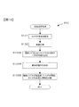
<初期設定処理>
図13は、第三の実施形態による初期設定処理の詳細を説明するフローチャートである。図13による処理は、前述の図4のステップS13において図6の処理に代えて実行される。図13のステップS131およびステップS132は、それぞれ図6における同一ステップ番号の処理と同様なので説明を省略する。図13のステップS133Bにおいて、CPU16は、CPU16内の不揮発性メモリに記憶されている合焦距離情報(x(L))、視度情報(x(F))に応じた焦点距離を得るように、可変焦点部材410および可変焦点部材310に対する印加電圧をそれぞれ決定する。
<Initial setting process>
FIG. 13 is a flowchart illustrating details of the initial setting process according to the third embodiment. The process shown in FIG. 13 is executed in place of the process shown in FIG. 6 in step S13 shown in FIG. Steps S131 and S132 in FIG. 13 are the same as the processes of the same step numbers in FIG. In step S133B of FIG. 13, the
具体的には、ステップS132で計測した温度情報と、不揮発性メモリに記憶されている温度情報(t)とに基づいて電圧VLoffを増減し、これらの温度差によって生じる可変焦点部材410の焦点距離の変動を抑制して不揮発性メモリに記憶されている合焦距離情報(x(L))に対応する撮影光学系400Cの合焦状態を得るために必要な印加電圧を求める。ここで、温度情報(t)および合焦距離情報(x(L))は、ステップS26(図4)において不揮発性メモリに記憶されたものとする。
Specifically, the voltage VLoff is increased / decreased based on the temperature information measured in step S132 and the temperature information (t) stored in the nonvolatile memory, and the focal length of the variable
CPU16はさらに、ステップS132で計測した温度情報と、不揮発性メモリに記憶されている温度情報(t)とに基づいて電圧VFoffを増減し、これらの温度差によって生じる可変焦点部材310の焦点距離の変動を抑制して不揮発性メモリに記憶されている視度情報(x(F))に対応する視度を得るために必要な印加電圧を求める。ここで、温度情報(t)および視度情報(x(F))は、ステップS26(図4)において不揮発性メモリに記憶されたものとする。
The
ステップS134Bにおいて、CPU16は、上記決定電圧を給電部511および501にそれぞれ指示してステップS135Bへ進む。これにより、可変焦点部材410(光学素子)および可変焦点部材310(光学素子)への給電電圧が制御される。ステップS135Bにおいて、CPU16は合焦距離情報(x(L))、視度情報(x(F))および電圧情報(V(L))、(V(F))をCPU16内の不揮発性メモリ(不図示)へそれぞれ記憶させて図13による処理を終了する。ここで、電圧情報(V(L))は、合焦距離情報(x(L))に対応させるため可変焦点部材410へ印加する電圧である。また、電圧情報(V(F))は、視度情報(x(F))に対応させるため可変焦点部材310へ印加する電圧である。
In step S134B, the
<温度フィードバック処理>
図14は、第三の実施形態による温度フィードバック処理の詳細を説明するフローチャートである。図14による処理は、前述の図4のステップS23において図7の処理に代えて実行される。図14のステップS231、S232、S233およびステップS234は、それぞれ図7における同一ステップ番号の処理と同様なので説明を省略する。
<Temperature feedback processing>
FIG. 14 is a flowchart for explaining the details of the temperature feedback processing according to the third embodiment. The process shown in FIG. 14 is executed in place of the process shown in FIG. 7 in step S23 shown in FIG. Steps S231, S232, S233, and S234 in FIG. 14 are the same as the processes of the same step numbers in FIG.
図14のステップS232Bにおいて、CPU16は撮影光学系400Cに設定されている合焦距離を維持するように可変焦点部材410に対する印加電圧を決定する。具体的には、ステップS231で計測した温度情報と初期設定時の温度情報とに所定値(たとえば5℃)以上の温度差がある場合、この温度差によって生じる可変焦点部材410の焦点距離の変動を抑制するように可変焦点部材410へ印加する電圧値を求める。
In step S232B of FIG. 14, the
ステップS233Bにおいて、CPU16は、上記決定電圧を給電部511に指示してステップS234Bへ進む。これにより、ステップS234Bにおいて可変焦点部材410(光学素子)への給電電圧が制御される。ステップS235Bにおいて、CPU16は合焦距離情報(x(L))、視度情報(x(F))および電圧情報(V(L))、(V(F))をCPU16内の不揮発性メモリ(不図示)へそれぞれ記憶させて図14による処理を終了する。図14によれば、温度変動に応じて印加電圧が微調整される。
In step S233B, the
<電源オフ処理>
図15は、第三の実施形態による電源オフ処理の詳細を説明するフローチャートである。図15による処理は、前述の図4のステップS27において図8の処理に代えて実行される。図15のステップS271Aにおいて、CPU16は、可変焦点部材410(光学素子)へ印加する電圧VLoffを給電部511に指示してステップS271Bへ進む。電圧VLoffは、直前のステップS26(図4)において電圧情報(V(L))としてCPU16の不揮発性メモリに記憶された電圧値である。これにより、撮影光学系400C合焦距離は、電源オフ処理直前に設定されていた状態が維持される。
<Power off process>
FIG. 15 is a flowchart for explaining the details of the power-off process according to the third embodiment. The process of FIG. 15 is executed in place of the process of FIG. 8 in step S27 of FIG. In step S271A in FIG. 15, the
ステップS271Bにおいて、CPU16は、可変焦点部材310(光学素子)へ印加する電圧VFoffを給電部501に指示してステップS272へ進む。電圧VFoffは、直前のステップS26(図4)において電圧情報(V(F))としてCPU16の不揮発性メモリに記憶された電圧値である。これにより、ファインダー300Bの視度は、電源オフ処理直前に設定されていた状態が維持される。
In step S271B, the
ステップS272において、CPU16は、カメラ本体電源のオフ処理を行って図15による処理を終了する。電源オフ処理では、給電部501および給電部511を除くカメラ内各部への給電を停止するように電源502へ指示を送る。
In step S272, the
以上説明した第三の実施形態によれば、第一の実施形態で得られた作用効果に加えて、以下の作用効果が得られる。
(1)印加電圧に応じて焦点距離を変える可変焦点部材410(液体レンズ)を撮影光学系400Cに備え、メインスイッチがオン操作されている場合はもちろん、メインスイッチオフ時(または無操作タイムアップ状態)にも可変焦点部材410に電圧印加を行うようにした(図12)。これにより、メインスイッチオフ状態(または無操作タイムアップ状態)にも撮影光学系400Cによる光学像が得られる。
According to the third embodiment described above, the following functions and effects can be obtained in addition to the functions and effects obtained in the first embodiment.
(1) The imaging optical system 400C is provided with a variable focal member 410 (liquid lens) that changes the focal length according to the applied voltage, and when the main switch is turned on, the main switch is turned off (or the non-operation time is increased). In the state), a voltage is applied to the variable focus member 410 (FIG. 12). As a result, an optical image by the photographing optical system 400C can be obtained even in the main switch off state (or the no-operation time-up state).
(2)メインスイッチオフ時(または無操作タイムアップ状態)に可変焦点部材410に印加する電圧を、電源オフ処理直前の印加電圧VLoffにしたので、電源オフ処理の前後で撮影光学系400Cの合焦距離が同じ値に維持され、光学像を観察中のユーザに違和感を与えることがない。
(2) Since the voltage applied to the
(3)メインスイッチオフ時(または無操作タイムアップ状態)において、電源の電池電圧が所定値VS未満の場合は可変焦点部材410への電圧印加を停止するようにしたので、電池残量が少ない状態では電池の過放電を防止できる。
(3) When the battery voltage of the power source is less than the predetermined value VS when the main switch is off (or in the no-operation time-up state), the voltage application to the
(4)カメラ内の温度情報を検出し、この温度情報を用いて可変焦点部材410に印加する電圧を増減するようにした。このような環境フィードバック処理を施すことにより、液体レンズのパワーが温度依存性を有する場合には検出温度に応じてパワーを補正し、電子カメラ1を使用する温度にかかわらず、撮影光学系400Cの合焦距離の変動を抑えることができる。
(4) Temperature information in the camera is detected, and the voltage applied to the
(5)CPU16内の不揮発性メモリ(不図示)へ記憶する情報として温度情報を含めるようにしたので、情報記憶時と異なる温度環境においても、情報記憶時と同じ撮影光学系400Cの合焦距離を再現できる。
(5) Since the temperature information is included as the information stored in the nonvolatile memory (not shown) in the
(変形例3)
上述した変形例2と同様に、メインスイッチオフ時(または無操作タイムアップ状態)においても、カメラ内の温度情報を検出し、この温度情報を用いて可変焦点部材410に印加する電圧を増減するようにしてもよい。このような環境フィードバック処理を施すことにより、液体レンズのパワーが温度依存性を有する場合には検出温度に応じてパワーを補正し、非使用中の電子カメラ1の温度にかかわらず、撮影光学系400Cの合焦距離の変動を抑えることができる。
(Modification 3)
Similar to the second modification described above, the temperature information in the camera is detected even when the main switch is off (or in the no-operation time-up state), and the voltage applied to the
(変形例4)
カメラ本体に着脱可能な撮影光学系400Cがカメラ本体に装着されているか否かを、周知のカメラ本体側レンズマウントと撮影光学系側のレンズマウント部との電気接点同士の接触を介して判定し、該判定結果に応じて撮影光学系400C側の可変焦点部材410へ電圧印加するか否かを決定してもよい。この場合のCPU16は、撮影光学系400Cの装着を検出した場合に給電部511に対して可変焦点部材410への電圧印加を許可する。CPU16は、撮影光学系400Cの非装着を検出した場合には給電部511に対して可変焦点部材410への電圧印加を禁止する(停止させる)。
(Modification 4)
Whether or not the photographic optical system 400C that can be attached to and detached from the camera body is attached to the camera body is determined through contact between the electrical contacts of the well-known camera body side lens mount and the photographic optical system side lens mount. Depending on the determination result, it may be determined whether or not to apply a voltage to the
(変形例5)
液体レンズの焦点距離を変化させる例として印加電圧を変化させる例を説明したが、液体レンズへ供給する電圧や液体レンズ周囲の磁界を変化させることによって焦点距離を変化させる場合にも本発明を適用してよい。また、液体レンズの液体に圧力を加えて液体レンズの焦点距離を変化させる場合には、当該圧力を圧電素子によって加える構成とすれば、上述した実施形態と同様に、印加電圧を変化させることによって液体レンズの焦点距離を変化させることができる。
(Modification 5)
The example in which the applied voltage is changed has been described as an example of changing the focal length of the liquid lens, but the present invention is also applied to the case where the focal length is changed by changing the voltage supplied to the liquid lens or the magnetic field around the liquid lens. You can do it. Further, when changing the focal length of the liquid lens by applying pressure to the liquid of the liquid lens, if the pressure is applied by a piezoelectric element, the applied voltage is changed as in the above-described embodiment. The focal length of the liquid lens can be changed.
(変形例6)
液体レンズの環境情報として温度情報を検出する例を説明したが、たとえば圧力(気圧)や湿度などを検出するセンサを設け、これらの検出情報を用いて視度または合焦距離を補正するようにすることもできる。たとえば上述の変形例5で示したような、液体に圧力を加えて液体レンズの焦点距離を変化させるタイプの可変焦点部材を使用する場合には、液体レンズの環境情報として圧力(気圧)情報を用いることは、特に有用であると考えられる。
(Modification 6)
Although an example of detecting temperature information as environmental information of the liquid lens has been described, for example, a sensor that detects pressure (atmospheric pressure), humidity, and the like is provided, and the diopter or focus distance is corrected using the detection information. You can also For example, when a variable focus member of a type that changes the focal length of the liquid lens by applying pressure to the liquid as shown in
電子カメラを例に説明したが、本発明はフィルムカメラにも適用することができる。また、観察光学系を備えた光学装置、たとえばヘッドマウントディスプレイなどの光学装置にも適用することができる。以上の説明はあくまで一例であり、上記の実施形態の構成に何ら限定されるものではなく、各実施形態および変形例は、適宜組み合わせてもかまわない。 Although an electronic camera has been described as an example, the present invention can also be applied to a film camera. The present invention can also be applied to an optical device provided with an observation optical system, for example, an optical device such as a head-mounted display. The above description is merely an example, and the present invention is not limited to the configuration of the above embodiment. Each embodiment and modification may be combined as appropriate.
1…電子カメラ
4…メインスイッチ
16…CPU(不揮発性メモリ)
300、300B…観察光学系
310、410…可変焦点部材(光学素子)
311…温度センサ
400、400B、400C…撮影光学系
401…撮像素子
501、511…給電部
502…電源
503…電圧計
DESCRIPTION OF
300, 300B ... Observation
311 ...
Claims (15)
電圧に応じて焦点距離を変化させる光学素子を有する光学系と、
前記メインスイッチの操作状態にかかわらず前記光学素子へ電圧を供給する電圧供給手段とを備えることを特徴とする光学装置。 A main switch that can be externally operated, power is supplied into the apparatus by the ON operation, and is stopped by the OFF operation;
An optical system having an optical element that changes a focal length according to a voltage;
An optical apparatus comprising: a voltage supply unit that supplies a voltage to the optical element regardless of an operation state of the main switch.
前記光学系は、前記光学装置に対して着脱自在に構成されていることを特徴とする光学装置。 The optical device according to claim 1.
The optical apparatus, wherein the optical system is configured to be detachable from the optical apparatus.
前記光学系が装着されているか否かを判定する判定手段をさらに備え、
前記電圧供給手段は、前記判定手段が否定判定した場合は前記電圧供給を停止することを特徴とする光学装置。 The optical device according to claim 2.
A determination means for determining whether or not the optical system is mounted;
An optical apparatus according to claim 1, wherein the voltage supply means stops the voltage supply when the determination means makes a negative determination.
装填されている電池の電圧を検出する電圧検出手段をさらに備え、
前記電圧供給手段は、前記電圧検出手段による検出電圧が所定値未満の場合は前記電圧供給を停止することを特徴とする光学装置。 In the optical device according to any one of claims 1 to 3,
Voltage detection means for detecting the voltage of the loaded battery,
The optical apparatus according to claim 1, wherein the voltage supply means stops the voltage supply when a voltage detected by the voltage detection means is less than a predetermined value.
前記電圧供給手段は、前記メインスイッチが前記オフ操作された状態のときに前記光学素子へ所定電圧を供給することを特徴とする光学装置。 In the optical device according to any one of claims 1 to 4,
The optical device, wherein the voltage supply means supplies a predetermined voltage to the optical element when the main switch is in the off-state.
前記所定電圧は、前記メインスイッチが前記オフ操作される直前に前記光学素子へ供給されていた電圧であることを特徴とする光学装置。 The optical device according to claim 5.
The optical apparatus according to claim 1, wherein the predetermined voltage is a voltage supplied to the optical element immediately before the main switch is turned off.
前記所定電圧は、所定の焦点距離に対応する電圧であることを特徴とする光学装置。 The optical device according to claim 5.
The optical device according to claim 1, wherein the predetermined voltage is a voltage corresponding to a predetermined focal length.
前記光学素子および/またはその近傍の環境情報を検出する環境情報検出手段をさらに備え、
前記電圧供給手段は、前記環境情報検出手段で検出された環境情報に応じて前記メインスイッチの前記オフ操作後に供給する電圧を補正することを特徴とする光学装置。 The optical device according to any one of claims 5 to 7,
Further comprising environmental information detecting means for detecting environmental information of the optical element and / or the vicinity thereof,
The voltage supply means corrects the voltage supplied after the off operation of the main switch according to the environment information detected by the environment information detection means.
前記環境情報検出手段は所定時間ごとに前記環境情報を検出し、
前記電圧供給手段は、前記環境情報検出手段で検出された最新の環境情報に応じて前記供給する電圧を制御することを特徴とする光学装置。 The optical device according to claim 8.
The environmental information detection means detects the environmental information every predetermined time,
The optical device is characterized in that the voltage supply means controls the supplied voltage in accordance with the latest environment information detected by the environment information detection means.
前記環境情報は温度を含み、
前記電圧供給手段は、前記温度に応じて前記供給する電圧を制御することを特徴とする光学装置。 The optical device according to claim 9.
The environmental information includes temperature,
The optical apparatus according to claim 1, wherein the voltage supply means controls the supplied voltage in accordance with the temperature.
前記光学素子は、第1液体材料と、該第1液体材料と屈折率が異なり、かつ該第1液体材料と混合しない第2液体材料とが容器内に封入され、前記供給電圧に応じて前記第1液体材料および前記第2液体材料の境界面形状を変化させることによって前記焦点距離を変化させることを特徴とする光学装置。 In the optical device according to any one of claims 1 to 10,
In the optical element, a first liquid material and a second liquid material having a refractive index different from that of the first liquid material and not mixed with the first liquid material are enclosed in a container, An optical apparatus, wherein the focal length is changed by changing a shape of an interface between the first liquid material and the second liquid material.
前記光学装置は撮影を行うカメラであり、
前記光学系は撮影光学系を含むことを特徴とする光学装置。 The optical device according to any one of claims 1 to 11,
The optical device is a camera for photographing;
The optical apparatus includes a photographing optical system.
前記撮影光学系は、前記供給電圧に応じてフォーカス調節を行うことを特徴とする光学装置。 The optical device according to claim 12, wherein
The optical apparatus, wherein the photographing optical system performs focus adjustment according to the supply voltage.
前記光学系は観察光学系を含むことを特徴とする光学装置。 The optical device according to any one of claims 1 to 13,
The optical apparatus includes an observation optical system.
前記観察光学系は、前記供給電圧に応じて視度調節を行うことを特徴とする光学装置。 The optical device according to claim 14.
The optical apparatus characterized in that the observation optical system performs diopter adjustment according to the supply voltage.
Priority Applications (1)
| Application Number | Priority Date | Filing Date | Title |
|---|---|---|---|
| JP2007259675A JP2009086584A (en) | 2007-10-03 | 2007-10-03 | Optical device |
Applications Claiming Priority (1)
| Application Number | Priority Date | Filing Date | Title |
|---|---|---|---|
| JP2007259675A JP2009086584A (en) | 2007-10-03 | 2007-10-03 | Optical device |
Publications (1)
| Publication Number | Publication Date |
|---|---|
| JP2009086584A true JP2009086584A (en) | 2009-04-23 |
Family
ID=40660030
Family Applications (1)
| Application Number | Title | Priority Date | Filing Date |
|---|---|---|---|
| JP2007259675A Pending JP2009086584A (en) | 2007-10-03 | 2007-10-03 | Optical device |
Country Status (1)
| Country | Link |
|---|---|
| JP (1) | JP2009086584A (en) |
Cited By (2)
| Publication number | Priority date | Publication date | Assignee | Title |
|---|---|---|---|---|
| WO2011052770A1 (en) * | 2009-10-30 | 2011-05-05 | 株式会社オプトエレクトロニクス | Optical information reader |
| EP2975455A1 (en) * | 2014-07-17 | 2016-01-20 | Ipek International GmbH | Focusing system and camera unit with a focusing system |
-
2007
- 2007-10-03 JP JP2007259675A patent/JP2009086584A/en active Pending
Cited By (4)
| Publication number | Priority date | Publication date | Assignee | Title |
|---|---|---|---|---|
| WO2011052770A1 (en) * | 2009-10-30 | 2011-05-05 | 株式会社オプトエレクトロニクス | Optical information reader |
| US8439266B2 (en) | 2009-10-30 | 2013-05-14 | Optoelectronics Co. Ltd. | Optical-information-reading apparatus |
| JP5637995B2 (en) * | 2009-10-30 | 2014-12-10 | 株式会社オプトエレクトロニクス | Optical information reader |
| EP2975455A1 (en) * | 2014-07-17 | 2016-01-20 | Ipek International GmbH | Focusing system and camera unit with a focusing system |
Similar Documents
| Publication | Publication Date | Title |
|---|---|---|
| US9071747B2 (en) | Digital camera | |
| US7825978B2 (en) | Imaging apparatus | |
| JP4738672B2 (en) | Camera with image stabilization function | |
| JP5570316B2 (en) | Imaging apparatus, control method thereof, and program | |
| US8032019B2 (en) | Camera body and imaging apparatus | |
| JP5967865B2 (en) | IMAGING DEVICE, IMAGING DEVICE CONTROL METHOD, AND PROGRAM | |
| JP2009282510A (en) | Interchangeable lens, camera body, and imaging apparatus | |
| JP5161443B2 (en) | camera | |
| US8427556B2 (en) | Image pickup apparatus with controlling of setting of position of cropping area | |
| JP5709629B2 (en) | Imaging apparatus and control method | |
| JP4068856B2 (en) | Imaging device | |
| JP2016208648A (en) | Electronic apparatus, control method, and program | |
| JP5245489B2 (en) | Optical device | |
| JP2009086584A (en) | Optical device | |
| JP2009086587A (en) | Optical system | |
| JP6032901B2 (en) | Imaging apparatus and imaging method | |
| JP5572564B2 (en) | Imaging apparatus and display control method thereof | |
| JP2010088196A (en) | Electronic equipment | |
| JP2008304636A (en) | Imaging apparatus and interchangeable lens | |
| JP2009086585A (en) | Display | |
| JP2019169822A (en) | Imaging apparatus and image display method in the same | |
| JP2009015184A (en) | Imaging device | |
| JP2009198956A (en) | Imaging apparatus and program | |
| JP2009086586A (en) | Observation apparatus | |
| JP2016212352A (en) | Lens unit, method for controlling the same, imaging apparatus, and camera system |