JP5709629B2 - Imaging apparatus and control method - Google Patents
Imaging apparatus and control method Download PDFInfo
- Publication number
- JP5709629B2 JP5709629B2 JP2011093241A JP2011093241A JP5709629B2 JP 5709629 B2 JP5709629 B2 JP 5709629B2 JP 2011093241 A JP2011093241 A JP 2011093241A JP 2011093241 A JP2011093241 A JP 2011093241A JP 5709629 B2 JP5709629 B2 JP 5709629B2
- Authority
- JP
- Japan
- Prior art keywords
- sensitivity
- imaging
- range
- changing
- setting
- Prior art date
- Legal status (The legal status is an assumption and is not a legal conclusion. Google has not performed a legal analysis and makes no representation as to the accuracy of the status listed.)
- Active
Links
Images


Classifications
-
- H—ELECTRICITY
- H04—ELECTRIC COMMUNICATION TECHNIQUE
- H04N—PICTORIAL COMMUNICATION, e.g. TELEVISION
- H04N23/00—Cameras or camera modules comprising electronic image sensors; Control thereof
- H04N23/70—Circuitry for compensating brightness variation in the scene
- H04N23/73—Circuitry for compensating brightness variation in the scene by influencing the exposure time
Description
本発明は、撮像感度を自動で設定することが可能な撮像装置及び制御方法に関する。 The present invention relates to an imaging apparatus and a control method capable of automatically setting imaging sensitivity.
従来、カメラのISO感度(撮像感度)に関し、ユーザの指示に従って設定したISO感度で適正な露出が得られない場合に、適正な露出となるように自動的にISO感度を変更する機能(以下、自動感度変更機能)が知られている。また、特許文献1では、露出演算により適正露出が得られない場合に設定撮像感度を変更する電子カメラにおいて、撮像感度がユーザの意図する範囲を超えないように、撮像感度を変更する際の制御上限感度及び制御下限感度を設定できるものが提案されている。
Conventionally, with respect to the ISO sensitivity (imaging sensitivity) of a camera, when an appropriate exposure cannot be obtained with an ISO sensitivity set in accordance with a user instruction (hereinafter, referred to as an ISO sensitivity) Automatic sensitivity changing function) is known. Further, in
しかしながら、上述の特許文献1では、ユーザは撮像感度を制御上限感度及び制御下限感度の間(感度制御範囲内)でしか指示することができない。そのため、ユーザの指示に従って設定可能な撮像感度は制限されてしまい、ユーザが意図する撮像感度に設定できない場合が考えられる。そのような場合、制御上限感度あるいは制御下限感度を変更することで設定可能な撮像感度の範囲を拡張することはできるが、制御上限感度あるいは制御下限感度を変更するためにユーザが指示する必要があり、すぐに意図した撮像感度に設定することができない。
However, in the above-described
そこで、本発明は、ユーザの指示に従って自動感度変更機能の感度制御範囲外の撮像感度を容易に設定でき、ユーザの指示に従って感度制御範囲外の撮像感度を設定した場合でもスムーズに自動感度変更を行うことができるようにすることを目的とする。 Therefore, the present invention can easily set the imaging sensitivity outside the sensitivity control range of the automatic sensitivity changing function according to the user's instruction, and smoothly change the automatic sensitivity even when the imaging sensitivity outside the sensitivity control range is set according to the user's instruction. The aim is to be able to do it.
上記目的を達成するために、本発明にかかる撮像装置は、被写体を撮像する撮像手段と、前記被写体の測光を行う測光手段と、ユーザの指示に従って、撮像感度を設定する感度設定手段と、前記測光手段の測光結果に基づいて、前記感度設定手段により設定された撮像感度を変更する感度変更手段と、ユーザの指示に従って、前記感度変更手段が前記感度設定手段により設定された撮像感度を変更する際の範囲を設定する範囲設定手段と、前記感度設定手段により設定された撮像感度が前記範囲設定手段により設定された範囲外の場合、前記感度設定手段により設定された露出制御値を変更する際の範囲を、前記感度設定手段により設定された撮像感度が含まれる範囲となるように変更する範囲変更手段と、を有することを特徴とする。 In order to achieve the above object, an imaging apparatus according to the present invention includes an imaging unit that images a subject, a photometric unit that performs photometry of the subject, a sensitivity setting unit that sets imaging sensitivity according to a user instruction, Based on the photometric result of the photometric means, a sensitivity changing means for changing the imaging sensitivity set by the sensitivity setting means, and the sensitivity changing means changes the imaging sensitivity set by the sensitivity setting means in accordance with a user instruction. a range setting means to set the range of time, the case where the imaging sensitivity set by the sensitivity setting means out of range set by the pre Kihan circumference setting means, the exposure set by the sensitivity setting means the range for changing the control value, and having a to the range changing means that changes to a range that includes the imaging sensitivity set by the sensitivity setting means.
被写体を撮像する撮像手段と、前記被写体の測光を行う測光手段と、を有する撮像装置の制御方法であって、ユーザの指示に従って、撮像感度を設定する感度設定ステップと、前記測光手段の測光結果に基づいて、前記感度設定ステップで設定された撮像感度を変更する感度変更ステップと、ユーザの指示に従って、前記感度変更ステップにおいて前記感度設定ステップで設定された撮像感度を変更する際の範囲を設定する範囲設定ステップと、前記感度設定ステップで設定された撮像感度が前記範囲設定ステップで設定された範囲外の場合、前記感度設定ステップで設定された撮像感度を変更する際の範囲を、前記感度設定ステップで設定された撮像感度が含まれる範囲となるように変更する範囲変更ステップと、を有することを特徴とする。 A method for controlling an imaging apparatus, comprising: an imaging unit that images a subject; and a photometric unit that performs photometry of the subject, a sensitivity setting step of setting imaging sensitivity according to a user instruction, and a photometric result of the photometric unit based on the sensitivity changing step of changing the imaging sensitivity set by the sensitivity setting step, in accordance with an instruction from the user, the range for changing the imaging sensitivity set by the sensitivity setting step in the sensitivity changing step setting a range setting step you, the case sensitivity setting imaging sensitivity set in step is set out of range before Kihan circumference setting step, when changing the imaging sensitivity set by the sensitivity setting step range, to characterized in that it has a, to the range changing step that changes to a range that includes the imaging sensitivity set by the sensitivity setting step of .
本発明によれば、ユーザの指示に従って自動感度変更機能の感度制御範囲外の撮像感度を容易に設定でき、ユーザの指示に従って感度制御範囲外の撮像感度を設定した場合でもスムーズに自動感度変更を行うことができる。 According to the present invention, it is possible to easily set the imaging sensitivity outside the sensitivity control range of the automatic sensitivity changing function according to the user's instruction, and smoothly change the automatic sensitivity even when the imaging sensitivity outside the sensitivity control range is set according to the user's instruction. It can be carried out.
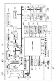
以下に、本発明の好ましい実施の形態を、添付の図面に基づいて詳細に説明する。図1は本発明にかかる実施の形態における撮像装置であるカメラの構成図である。カメラ本体100には、カメラ本体100に対して着脱可能な交換レンズである撮影レンズ220が装着される。
Hereinafter, preferred embodiments of the present invention will be described in detail with reference to the accompanying drawings. FIG. 1 is a configuration diagram of a camera which is an imaging apparatus according to an embodiment of the present invention. The
カメラ本体100において、主ミラー2は、撮影光路に対し、観察状態で斜めの位置に撮影状態で退避した位置に移動自在である。サブミラー3は、撮影光路に対して斜めに配置され、主ミラー2を透過した光束を、カメラ本体100の下方に向けて反射し、焦点検出装置6に導く。
In the
シャッタ4は撮影光路に進退自在に移動でき、撮像素子5の露光時間を制御する。撮像素子5は、CCDセンサやCMOSセンサ等から構成され、撮影レンズ220を通して結像した被写体の光学像を光電変換する。測光センサ7は、主ミラー2で反射した光束の一部を入射し、被写体の輝度に関する情報を測光回路42に出力する。
The
A/D変換器16は、撮像素子5からのアナログ撮像信号をデジタル撮像信号に変換する。なお、撮像感度は、例えば、撮像素子5に蓄積される信号電荷の検出感度、もしくは不図示の増幅回路の増幅利得などを変化させることで変更することが可能であり、システム制御部50により制御される。タイミング発生回路18は、撮像素子5、A/D変換器16およびD/A変換器26にクロック信号を供給する。タイミング発生回路18は、メモリ制御回路22およびシステム制御部50により制御される。
The A /
画像処理回路20は、A/D変換器16あるいはメモリ制御回路22からのデジタル撮像信号に対し、画素補間処理、色変換処理、AWB(オートホワイトバランス)処理等の各種画像処理を行い、画像信号を生成する。焦点検出装置6は、複数の焦点検出エリアを有する位相差検出用のセンサを含む。
The image processing circuit 20 performs various types of image processing such as pixel interpolation processing, color conversion processing, and AWB (auto white balance) processing on the digital image pickup signal from the A /
システム制御部50は、焦点検出装置6の蓄積制御や読み出し制御を行い、周知の位相差検出方法により被写体距離に関する情報であるデフォーカス量を算出する。システム制御部50は、カメラ本体100全体の動作やデフォーカス量などから、撮影レンズ220のフォーカス駆動や絞り駆動を制御する。また、システム制御部50は、図示しない記憶制御機能および表示制御機能を有する。
The
メモリ制御回路22は、A/D変換器16、タイミング発生回路18、画像処理回路20、画像表示メモリ24、D/A変換器26、メモリ30および圧縮伸長回路32を制御する。
The
画像処理回路20からの画像信号あるいはA/D変換器16からのデジタル撮像信号は、メモリ制御回路22を介して画像表示メモリ24、メモリ30やシステム制御部50に送られる。
An image signal from the image processing circuit 20 or a digital image pickup signal from the A /
画像表示部28は、LCDやTFT等から構成される。画像表示メモリ24に書き込まれた表示用画像データやカメラの設定メニューなどの画像データは、D/A変換器26を介して画像表示部28に送られ、画像表示部28に表示される。メモリ30は、生成された静止画像を格納する。また、メモリ30は、システム制御部50の作業領域としても使用される。
The
圧縮伸長回路32は、適応離散コサイン変換(ADCT)等により画像データを圧縮伸長する。圧縮伸長回路32は、メモリ30に格納された画像データを読み込んで圧縮処理あるいは伸長処理を行い、処理を終えた画像データを再びメモリ30に書き込む。
The compression /
露光制御回路40は、シャッタ4を制御するとともに、システム制御部50を介して撮影レンズ220の絞り224も制御する。測光回路42は、測光センサ7から出力される情報をシステム制御部50に出力する。
The
メモリ52は、システム制御部50の動作用の定数、変数、コンピュータプログラム等のデータを記憶する。不揮発性メモリ54は、データを電気的に消去・記録可能なメモリである。不揮発性メモリ54には、EEPROM等が用いられる。
The
情報出力部56は、文字、画像、音声等を用いてカメラ本体100の動作状態やメッセージ等の情報を出力する。情報出力部56は、液晶表示素子やスピーカ等から構成される。
The
モードダイヤル60は、撮像モード(マニュアルモード、絞り優先モード、シャッタスピード優先モードやプログラムモード等)の切り替えを行うための操作部材である。シャッタスイッチ62は、撮像準備スイッチ(SW1)と撮影開始スイッチ(SW2)からなる。シャッタボタン(図示せず)の第1ストローク操作(半押し)により、撮像準備スイッチ(SW1)がONとなり、測光(AE処理)およびAF処理等の撮像準備動作が開始する。さらに、シャッタボタンの第2ストローク操作(全押し)により、撮影開始スイッチ(SW2)がONとなり、撮像動作を開始する。
The
ここで、撮像動作には、絞り224の駆動、シャッタ4の移動、撮像素子5からの撮像信号に基づいて画像処理回路20で画像信号を生成する動作、およびメモリ制御回路22を介して画像信号をメモリ30に書き込む動作などが含まれる。また、メモリ30から画像データを読み出して、圧縮伸長回路32で圧縮し、記録媒体200、210に記録する動作も含まれる。これら一連の撮像動作は、記録用画像の取得動作とも称される。
Here, in the imaging operation, the
記録媒体200、210は、半導体メモリや光ディスク等から構成される。操作部70は、各種ボタンやタッチパネル等を含み、カメラ本体100の機能選択や各種設定を行うためのメニュー項目を決定する場合などに操作される。
The
電源制御回路78は、電池残量の検出を行う電池検出回路、電池からの電源電圧を所定の動作電圧に変換するDC−DCコンバータ、通電するブロックを切り替えるスイッチ回路等を含む。電池80はカメラ本体100に着脱可能である。電池80内の電源86には、アルカリ電池やリチウム電池等の一次電池や、NiMH電池、Li電池等の二次電池が使用される。コネクタ82、84は、電源86とカメラ本体100との電気的接続を行う。
The power
インタフェース90、94は、それぞれ記録媒体200、210と通信を行うためのものである。コネクタ92、96は、それぞれ記録媒体200、210に接続される。記録媒体着脱検知器98は、コネクタ92、96に記録媒体200、210がそれぞれ装着されているか否かを検知する。
The
通信部110は、RS232C、USB、IEEE1394、無線通信等の通信機能を有する。コネクタ112は、通信部110を介してカメラ本体100に他の機器を接続するものである。無線通信を行う場合、通信部110にはアンテナが接続される。
The
記録媒体200、210は、それぞれカメラ本体100と通信を行うためのインタフェース204、214、およびカメラ本体100と電気的接続を行うコネクタ206、216を有する。記録部202、212には、それぞれカメラ本体100から出力される圧縮画像データが書き込まれる。
The
一方、撮影レンズ220において、撮像レンズ群1は、複数のレンズから構成され、光軸方向に移動してフォーカス調整を行うフォーカスレンズや、光軸方向に移動して変倍を行うズームレンズを含む。絞り224は、撮像素子5に入射する光束の光量を調節する。撮像光学系は、撮像レンズ群1および絞り224から構成される。
On the other hand, in the taking
レンズ駆動回路226は、システム制御部50からの制御信号に従って、フォーカスレンズ、ズームレンズおよび絞り224を駆動する不図示のアクチュエータを制御する。また、レンズ駆動回路226は、撮影レンズ動作用の定数、変数、プログラム等を記憶するメモリ機能を備える。その他、レンズ駆動回路226は、撮影レンズ固有の番号等の識別情報、管理情報、開放絞り値や最小絞り値、焦点距離等の機能情報、現在や過去の各設定値等を記憶する不揮発メモリの機能も備える。
The
コネクタ228は、カメラ本体100の通信接点部41と接続され、レンズ駆動回路226およびシステム制御部50間の通信を可能とする。また、コネクタ228は、電源86からの電源電圧を撮影レンズ220内に供給する。
The
図2は画像表示部28に表示されるISO感度(撮像感度)に関する設定画面を示す図である。
FIG. 2 is a diagram showing a setting screen related to ISO sensitivity (imaging sensitivity) displayed on the
図2(a)は、ISO感度に関する複数の項目が表示される画面を示しており、ユーザが操作部70を操作することで任意の項目の選択及び決定が実行される。ISO感度設定を選択して決定すると、図2(b)に示す画面が表示され、ユーザは表示された複数の値から任意のISO感度を撮像に用いるISO感度として指示することができる。この時にユーザの指示に従って設定されたISO感度(以下、設定感度とする)は、システム制御部50により不図示の内部メモリに記憶される。以下では、操作部70などで受け付けたユーザの指示に従って各種設定を行うことを、単にユーザが設定すると表現することとする。
FIG. 2A shows a screen on which a plurality of items related to ISO sensitivity are displayed, and selection and determination of arbitrary items are executed by the user operating the
なお、図2(b)で示した画面はユーザが任意のISO感度を設定するための画面の一例であって、設定可能なISO感度の数や設定可能なISO感度の値などは図2(b)に示したものに限定されない。また、図2(b)では、設定可能なISO感度を同時に複数表示する表示形態を示しているが、1つのISO感度の値のみを表示して操作部70への操作に応じて表示するISO感度の値を変更するような表示形態であっても構わない。また、ユーザが操作部70を操作して所望するISO感度を入力することでISO感度を設定するようにしてもよい。また、図2に示したようなメニュー画面からISO感度を設定するのではなく、ISO感度設定用の操作部材を操作することでISO感度を設定する構成でもよい。
The screen shown in FIG. 2B is an example of a screen for the user to set an arbitrary ISO sensitivity. The number of ISO sensitivities that can be set and the ISO sensitivity values that can be set are shown in FIG. It is not limited to what was shown to b). 2B shows a display form in which a plurality of settable ISO sensitivities are displayed at the same time, but only one ISO sensitivity value is displayed and displayed in response to an operation on the
図2(c)及び(d)は、自動感度変更の有無を設定するための画面である。図2(b)は、自動感度変更の設定を変更するか自動感度変更の設定を終了するかを選択可能な状態を示しており、選択中の項目が破線で囲まれている。 FIGS. 2C and 2D are screens for setting whether or not to change the automatic sensitivity. FIG. 2B shows a state in which it is possible to select whether to change the automatic sensitivity change setting or to end the automatic sensitivity change setting, and the item being selected is surrounded by a broken line.
そして、自動感度変更の設定を変更することを決定すると図2(d)に示した状態となり、自動感度変更を行うか否かを選択可能になる。 When it is decided to change the setting for changing the automatic sensitivity, the state shown in FIG. 2D is obtained, and it is possible to select whether or not to change the automatic sensitivity.
なお、図2(c)及び(d)で示した画面はユーザが自動感度変更の有無を設定するための画面の一例であって、図2(c)及び(d)とは異なる画面に従って設定するようにしてもよい。あるいは、自動感度変更の有無を設定するための操作部材を操作することで設定するようにしてもよい。 The screens shown in FIGS. 2C and 2D are examples of screens for the user to set whether or not to change the automatic sensitivity, and are set according to a screen different from FIGS. 2C and 2D. You may make it do. Or you may make it set by operating the operation member for setting the presence or absence of an automatic sensitivity change.
図2(e)及び(f)は、自動感度変更を行う際の制御範囲(以下、感度制御範囲ともいう)を設定するための画面である。図2(e)では、制御範囲の上限値及び下限値をそれぞれ設定することができる。図2(e)に示す状態において上限値を設定することを決定すると、図2(f)に示した状態となり、上限値の設定が可能となる。この時に設定された自動感度変更を行う際の制御範囲の上限値及び下限値は、設定上限値及び設定下限値としてシステム制御部50により内部メモリに記憶される。
FIGS. 2E and 2F are screens for setting a control range (hereinafter also referred to as a sensitivity control range) when automatic sensitivity change is performed. In FIG.2 (e), the upper limit value and lower limit value of a control range can be set, respectively. If it is decided to set the upper limit value in the state shown in FIG. 2 (e), the state shown in FIG. 2 (f) is obtained, and the upper limit value can be set. The upper limit value and the lower limit value of the control range when performing the automatic sensitivity change set at this time are stored in the internal memory by the
本実施の形態では、図2(e)及び(f)において設定可能な上限値及び下限値と、図2(b)において設定可能なISO感度とはそれぞれ独立している。そのため、図2(e)及び(f)において設定した上限値及び下限値を超えたISO感度を図2(b)において設定することができる。すなわち、ユーザが設定した自動感度変更の制御範囲外のISO感度を設定することができる。例えば、ユーザが自動感度変更の制御範囲の上限値を「ISO800」に設定した状態でも、ユーザが「ISO800」よりも高いISO感度である「ISO3200」を設定することができる。同様に、ユーザが自動感度変更の制御範囲の下限値を「ISO400」に設定した状態でも、ユーザが「ISO400」よりも低いISO感度である「ISO100」を設定することができる。 In the present embodiment, the upper and lower limit values that can be set in FIGS. 2E and 2F and the ISO sensitivity that can be set in FIG. 2B are independent of each other. Therefore, the ISO sensitivity exceeding the upper limit value and the lower limit value set in FIGS. 2 (e) and 2 (f) can be set in FIG. 2 (b). That is, it is possible to set the ISO sensitivity outside the control range of the automatic sensitivity change set by the user. For example, even when the user sets the upper limit of the control range for automatic sensitivity change to “ISO800”, the user can set “ISO3200”, which is an ISO sensitivity higher than “ISO800”. Similarly, even when the user sets the lower limit value of the control range for automatic sensitivity change to “ISO400”, the user can set “ISO100”, which is an ISO sensitivity lower than “ISO400”.
なお、自動感度変更を行う際の制御範囲の設定について、上限値及び下限値の両方が設定可能ではなく、いずれか一方のみ設定可能な構成であってもよい。あるいは、予め決められた複数の範囲から任意の範囲を制御範囲として設定する構成であってもよい。 In addition, about the setting of the control range at the time of performing an automatic sensitivity change, both the upper limit value and the lower limit value cannot be set, and the structure which can set only either one may be sufficient. Alternatively, an arbitrary range may be set as a control range from a plurality of predetermined ranges.
このように、ユーザが設定した自動感度変更の制御範囲外のISO感度を、撮影時のISO感度としてユーザが設定できるため、ユーザが自動感度変更の制御範囲外のISO感度で撮影したい場合であっても、容易に所望するISO感度を設定することができる。そのため、所望するISO感度を設定するための手間が軽減され、シャッターチャンスを逃すことを軽減することができる。 In this way, since the ISO sensitivity outside the control range of the automatic sensitivity change set by the user can be set as the ISO sensitivity at the time of shooting, the user wants to shoot at an ISO sensitivity outside the control range of the automatic sensitivity change. However, the desired ISO sensitivity can be easily set. Therefore, the effort for setting the desired ISO sensitivity is reduced, and missed photo opportunities can be reduced.
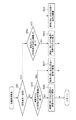
図3は本実施の形態におけるカメラでの各種処理の手順を示すフローチャートである。この処理は主にシステム制御部50によって実行される。
FIG. 3 is a flowchart showing various processing procedures in the camera according to the present embodiment. This process is mainly executed by the
ステップS1でシステム制御部50は、レジスタの初期化、データの初期化等の初期設定を行う。ステップS2でシステム制御部50は、モードダイヤル60、シャッタスイッチ62、操作部70等の状態を検出する。
In step S1, the
ステップS3でシステム制御部50は、カメラの各種設定を行うための操作部70に含まれるMENUボタンが押されているか否かを判別する。MENUボタンが押されている場合、ステップS4でシステム制御部50は、操作部70への操作などに基づいてISO感度に関する各種項目の設定を行い、ステップS5の処理に進む。ここで、ISO感度に関する各種項目の設定方法については図2を用いて前述したので省略する。一方、MENUボタンが押されていない場合、システム制御部50は、ステップS6の処理に進む。
In step S3, the
ステップS5でシステム制御部50は、ステップS4で設定された設定感度、設定上限値及び設定下限値に基づいて、実際に自動感度変更を行う際の制御範囲の上限値及び下限値である、制御上限値及び制御下限値を設定する。以下、図4を用いて制御上限値及び制御下限値の設定処理(自動感度変更を行う際の感度制御範囲の変更処理)について説明する。
In step S5, the
ステップ11でシステム制御部50は、設定感度と設定上限値とを比較する。その結果、設定感度が設定上限値より高ければ、ステップS12でシステム制御部50は、設定感度を制御上限値として内部メモリに記憶し、ステップS14に進む。一方、設定感度が設定上限値より高くなければ、ステップS13へ進む。
In
ステップS13でシステム制御部50は、設定上限値を制御上限値として内部メモリに記憶し、ステップS14に進む。
In step S13, the
ステップS14でシステム制御部50は、設定感度と設定下限値とを比較する。その結果、設定感度が設定下限値より低ければ、ステップS15でシステム制御部50は、設定感度を制御下限値として内部メモリに記憶し、制御上限値及び制御下限値の設定処理を終了する。一方、設定感度が設定下限値より低くなければ、ステップS16へ進む。
In step S14, the
ステップS16でシステム制御部50は、設定下限値を制御下限値として内部メモリに記憶し、制御上限値及び制御下限値の設定処理を終了する。
In step S16, the
以上のように、設定感度が設定上限値及び設定下限値により規定される制御範囲外である場合には、制御範囲の上限あるいは下限が設定感度となるように制御範囲を変更する。 As described above, when the set sensitivity is outside the control range defined by the set upper limit value and the set lower limit value, the control range is changed so that the upper limit or the lower limit of the control range becomes the set sensitivity.
これにより、ユーザが自動感度変更を行う際の制御範囲を設定し、かつ、ユーザが制御範囲外の撮像感度を撮像に用いる撮像感度として設定した状態において適正露出が得られない場合であっても、スムーズに自動感度変更を行うことができる。 Thus, even when the user sets the control range when performing automatic sensitivity change and the user sets the imaging sensitivity outside the control range as the imaging sensitivity used for imaging, the proper exposure cannot be obtained. Smooth, automatic sensitivity change can be performed.
また、設定感度が設定上限値と設定下限値の間(感度制御範囲内)に場合には、設定上限値及び設定下限値をそのまま制御上限値及び制御下限値とするので、ユーザが設定した感度制御範囲を変更せずに実際に自動感度変更を行う際の制御範囲とすることになる。そのため、ユーザの意図する範囲を超えないように自動感度変更を行うことができる。 In addition, when the set sensitivity is between the set upper limit value and the set lower limit value (within the sensitivity control range), the set upper limit value and the set lower limit value are directly used as the control upper limit value and the control lower limit value. This is the control range when the automatic sensitivity change is actually performed without changing the control range. Therefore, the automatic sensitivity change can be performed so as not to exceed the range intended by the user.
図3に戻って、ステップS6でシステム制御部50は、ステップS3でMENUボタンが押されていない場合、SW1がオンか否かを判別する。SW1がオフである場合、システム制御部50は、ステップS14の処理に進む。
Returning to FIG. 3, in step S <b> 6, the
SW1がオンである場合、ステップS7でシステム制御部50は、装着された撮影レンズ220の各種情報を読み取る。撮影レンズ220からレンズ情報を取得する際、システム制御部50は、撮影レンズ220と通信を行い、撮影レンズ220のレンズ情報を取得する。レンズ情報には、レンズ固有情報、焦点距離、絞り値、フォーカスレンズ位置などの情報が含まれている。
If SW1 is on, the
ステップS8でシステム制御部50は、被写体に焦点を合わせるために、周知の位相差検出方式による測距演算を行う。ステップS9でシステム制御部50は、ステップS8での測距演算によるデータ(デフォーカス量など)をもとに、レンズ駆動量を算出してレンズを駆動させる。
In step S8, the
ステップS10でシステム制御部50は、測光回路42からの出力、撮影モード等のカメラ設定情報に基づいて、撮像に用いる絞り値、シャッタスピード、ISO感度などの露出制御値を決定するための測光演算処理を行う。
In step S10, the
図5はステップS10における測光演算処理の手順を示すフローチャートである。 FIG. 5 is a flowchart showing the procedure of the photometric calculation process in step S10.
ステップS21でシステム制御部50は、モードダイヤル60によりマニュアルモードが設定されているか否かを判別する。マニュアルモードが設定されている場合、ステップS22でシステム制御部50は、ユーザが設定しているシャッタスピードや絞り値に基づいて露出演算を行う。
In step S <b> 21, the
一方、ステップS21の判別結果からマニュアルモードでない場合、ステップS23でシステム制御部50は、絞り優先(Av優先)モードであるか否かを判別する。Av優先モードである場合、ステップS24でシステム制御部50は、Av優先モード用露出演算を行う。
On the other hand, if the manual mode is not determined based on the determination result of step S21, the
図6はステップS24におけるAv優先モード用露出演算処理の手順を示すフローチャートである。ステップS31でシステム制御部50は、ユーザが設定した絞り値及びISO感度と、測光回路42から得られた輝度情報とから、撮像に用いるシャッタスピード(Tv)を演算する。
FIG. 6 is a flowchart showing the procedure of Av priority mode exposure calculation processing in step S24. In step S31, the
そして、ステップS32でシステム制御部50は、輝度情報とステップS31の演算結果から露出が適正露出であるか否かを判別する。露出が適正露出である場合、システム制御部50は本処理を終了し、元の処理に復帰する。一方、露出が適正露出でない場合、ステップS33の処理に進む。
In step S32, the
ステップS33でシステム制御部50は、自動感度変更の項目が「する」に選択されているか否かを判別する。自動感度変更の項目が「する」に選択されている場合、ステップS34に進み、「しない」に選択されている場合は、システム制御部50は本処理を終了し、元の処理に復帰する。
In step S <b> 33, the
ステップS34でシステム制御部50は、自動感度変更処理に進み、適正露出に近づけるように設定感度を変更させる。図7はステップS34における自動感度変更処理の手順を示すフローチャートである。
In step S34, the
ステップS41でシステム制御部50は、輝度情報とS31の演算結果から適正露出となるISO感度を演算し、適正露出に近づけるために、設定感度をどちら側に変更させるか判断する。そして、高感度側に変更させる場合はステップS42に進み、低感度側に変更させる場合はステップS45に進む。
In step S41, the
ステップS42でシステム制御部50は、演算されたISO感度と制御上限値とを比較して、演算されたISO感度が制御上限値より高くなければ、ステップS43に進む。ステップS43でシステム制御部50は、演算されたISO感度を撮像に用いるISO感度として決定して元の処理に復帰する。一方、演算されたISO感度が制御上限値より高ければ、ステップS44に進む。ステップS44でシステム制御部50は、制御上限値を撮像に用いるISO感度として決定して元の処理に復帰する。
In step S42, the
ステップS45でシステム制御部50は、演算されたISO感度と制御下限値とを比較して、演算されたISO感度が制御下限値より低くなければ、ステップS46に進む。ステップS46でシステム制御部50は、演算されたISO感度を撮像に用いるISO感度として決定して元の処理に復帰する。一方、演算されたISO感度が制御下限値より低ければ、ステップS47へ進む。ステップS47でシステム制御部50は、制御下限値を撮像に用いるISO感度に決定して元の処理に復帰する。
In step S45, the
図5に戻って、ステップS23の判別結果からAv優先モードでない場合、ステップS25でシステム制御部50は、シャッタスピード優先(Tv優先)モードであるか否かを判別する。Tv優先モードである場合、ステップS26でシステム制御部50は、Tv優先モード用露出演算を行う。
Returning to FIG. 5, if it is not the Av priority mode from the determination result of Step S23, the
Tv優先モード用露出演算処理の手順は、図6で示したAv優先モード用露出演算処理の手順とステップS31のみが異なっており、Tv優先モード用露出演算処理では撮像に用いる絞り値(Av)を演算する。そして、Tv優先モード用露出演算処理の終了後は元の処理に復帰する。 The procedure of the exposure calculation process for the Tv priority mode is different from the procedure of the exposure calculation process for the Av priority mode shown in FIG. 6 only in step S31. In the exposure calculation process for the Tv priority mode, the aperture value (Av) used for imaging is different. Is calculated. Then, after the exposure calculation process for the Tv priority mode is completed, the process returns to the original process.
図5に戻って、ステップS25の判別結果からTv優先モードでない場合、ステップS27でシステム制御部50は、プログラムモードであるか否かを判別する。プログラムモードである場合、ステップS28でシステム制御部50は、プログラムモード用露出演算を行う。
Returning to FIG. 5, if the Tv priority mode is not selected from the determination result of step S25, the
プログラムモード用露出演算処理の手順は、図6で示したAv優先モード用露出演算処理の手順とステップS31のみが異なっており、プログラムモード用露出演算処理では撮像に用いる絞り値(Av)及びシャッタスピード(Tv)を演算する。そして、プログラムモード用露出演算処理の終了後は元の処理に復帰する。 The procedure for the exposure calculation process for the program mode differs from the procedure for the exposure calculation process for the Av priority mode shown in FIG. 6 only in step S31. In the exposure calculation process for the program mode, the aperture value (Av) and shutter used for imaging are different. The speed (Tv) is calculated. Then, after the program mode exposure calculation process is completed, the process returns to the original process.
図5に戻って、ステップS27の判別結果からプログラムモードでない場合、ステップS29でシステム制御部50は、上記のモード以外の撮像モードであると判断し、その他のモード用測光演算処理を行い、本処理を終了して元の処理に復帰する。
Returning to FIG. 5, if it is not the program mode from the determination result of step S27, the
ステップS10で測光演算処理を行った後、ステップS11でシステム制御部50は、測光演算処理等により決定された絞り値、シャッタスピード、ISO感度等のカメラの情報を画像表示部28に表示する。
After performing the photometric calculation process in step S10, in step S11, the
ステップS12でシステム制御部50は、SW2がオンであるか否かを判別する。SW2がオンである場合、ステップ13でシステム制御部50は、周知の撮像素子5のゲイン設定、蓄積動作および読み出し動作を行うとともに、画像処理、画像書き込み等の静止画の撮像動作を行う。この後、システム制御部50はステップS2の処理に戻る。
In step S12, the
一方、ステップS12でSW2がオフである場合、ステップ14でシステム制御部50は、不図示の電源SWがオンであるか否かを判別する。電源SWがオンである場合、システム制御部50はステップS2の処理に戻る。
On the other hand, if SW2 is off in step S12, in
一方、電源SWがオフである場合、ステップS15でシステム制御部50は、カメラの動作を終了させるために、各種回路への電源オフの指示やデータの退避等の終了設定を行い、本処理を終了する。
On the other hand, when the power SW is off, in step S15, the
以上のように、上記の実施の形態では、自動感度変更を行う際の感度制御範囲と撮像に用いる撮像感度とをそれぞれ独立してユーザが指示することができる。そのため、ユーザが指示した自動感度変更の感度制御範囲外の撮像感度でユーザが撮影したい場合であっても、容易に所望する撮像感度を設定することができ、所望する撮像感度を設定するための手間が軽減され、シャッターチャンスを逃すことを軽減できる。 As described above, in the above-described embodiment, the user can independently designate the sensitivity control range when performing automatic sensitivity change and the imaging sensitivity used for imaging. Therefore, even when the user wants to take an image with an imaging sensitivity outside the sensitivity control range of the automatic sensitivity change instructed by the user, the desired imaging sensitivity can be easily set, and the desired imaging sensitivity can be set. Time and effort are reduced, and missed shutter opportunities can be reduced.
また、ユーザの指示に従って自動感度変更を行う際の制御範囲設定を行い、かつ、ユーザが感度制御範囲外の撮像感度を撮像に用いる撮像感度として指示した状態で適正露出が得られない場合、制御範囲変更を行うことでスムーズに自動感度変更を行うことができる。 In addition, when the control range is set when the automatic sensitivity change is performed according to the user's instruction and the appropriate exposure cannot be obtained with the user instructing the imaging sensitivity outside the sensitivity control range as the imaging sensitivity used for imaging, the control is performed. By changing the range, the automatic sensitivity can be changed smoothly.
また、ユーザが指示した撮像感度が、ユーザが指示した感度制御範囲内である場合には、ユーザが指示した感度制御範囲内で撮像感度の変更が行われるため、ユーザの意図する範囲を超えないように自動感度変更を行うことができる。 Further, when the imaging sensitivity designated by the user is within the sensitivity control range designated by the user, the imaging sensitivity is changed within the sensitivity control range designated by the user, and therefore does not exceed the range intended by the user. Thus, automatic sensitivity change can be performed.
なお、上記実施の形態では、カメラ本体に交換レンズを装着した構成について説明したが、カメラ本体が撮影レンズを内蔵している構成であっても構わない。 In the above-described embodiment, the configuration in which the interchangeable lens is attached to the camera body has been described. However, the camera body may have a configuration in which a photographic lens is incorporated.
また、測光センサや測光回路を用いた測光結果ではなく、撮像素子を用いた測光結果に基づいて露出演算を行ってもよい。 Further, the exposure calculation may be performed based on the photometric result using the image sensor instead of the photometric result using the photometric sensor or the photometric circuit.
また、撮像モードがマニュアルモードの場合には自動感度変更を行わない構成を説明したが、マニュアルモードであっても自動露出変更が可能な構成にしてもよい。 In addition, the configuration in which the automatic sensitivity change is not performed when the imaging mode is the manual mode has been described, but a configuration in which the automatic exposure change is possible even in the manual mode.
また、上記のような、ユーザが指示した感度で適正露出が得られない場合に感度をカメラが自動的に変更する機能だけでなく、ユーザの指示に従って撮像感度を設定することなく、適正露出となるような撮像感度をカメラが自動的に設定する機能を有していてもよい。 In addition to the function for automatically changing the sensitivity when the appropriate exposure cannot be obtained at the sensitivity specified by the user as described above, the proper exposure can be obtained without setting the imaging sensitivity according to the user's instruction. The camera may have a function of automatically setting such imaging sensitivity.
また、ユーザの指示に従って露出制御における目標露出を適正露出とは異なる露出に補正可能な、いわゆる露出補正機能を有する構成においては、ユーザが指示した撮像感度で目標露出とならない場合に自動感度変更を行うようにしてもよい。 Further, in a configuration having a so-called exposure correction function that can correct the target exposure in exposure control to an exposure different from the appropriate exposure according to the user's instruction, the automatic sensitivity change is performed when the target exposure does not reach the imaging sensitivity specified by the user You may make it perform.
28 画像表示部
42 測光回路
50 システム制御部
60 モードダイヤル
100 カメラ本体
28
Claims (7)
前記被写体の測光を行う測光手段と、
ユーザの指示に従って、撮像感度を設定する感度設定手段と、
前記測光手段の測光結果に基づいて、前記感度設定手段により設定された撮像感度を変更する感度変更手段と、
ユーザの指示に従って、前記感度変更手段が前記感度設定手段により設定された撮像感度を変更する際の範囲を設定する範囲設定手段と、
前記感度設定手段により設定された撮像感度が前記範囲設定手段により設定された範囲外の場合、前記感度設定手段により設定された露出制御値を変更する際の範囲を、前記感度設定手段により設定された撮像感度が含まれる範囲となるように変更する範囲変更手段と、を有することを特徴とする撮像装置。 Imaging means for imaging a subject;
Metering means for metering the subject;
Sensitivity setting means for setting the imaging sensitivity according to a user instruction;
Sensitivity changing means for changing the imaging sensitivity set by the sensitivity setting means based on the photometric result of the photometric means;
According to the user's instructions, the range setting means to set the range at which the sensitivity change means changes the imaging sensitivity set by the sensitivity setting means,
If the imaging sensitivity set by the sensitivity setting means out of range set by the pre Kihan circumference setting means, the range for changing the exposure control value set by the sensitivity setting unit, the sensitivity setting means imaging apparatus characterized by having a range change means to change to be in the range that includes the imaging sensitivity set by the.
ユーザの指示に従って、撮像感度を設定する感度設定ステップと、
前記測光手段の測光結果に基づいて、前記感度設定ステップで設定された撮像感度を変更する感度変更ステップと、
ユーザの指示に従って、前記感度変更ステップにおいて前記感度設定ステップで設定された撮像感度を変更する際の範囲を設定する範囲設定ステップと、
前記感度設定ステップで設定された撮像感度が前記範囲設定ステップで設定された範囲外の場合、前記感度設定ステップで設定された撮像感度を変更する際の範囲を、前記感度設定ステップで設定された撮像感度が含まれる範囲となるように変更する範囲変更ステップと、を有することを特徴とする撮像装置の制御方法。 An imaging apparatus control method comprising: an imaging unit that images a subject; and a photometric unit that performs photometry of the subject,
A sensitivity setting step for setting the imaging sensitivity in accordance with a user instruction;
A sensitivity changing step for changing the imaging sensitivity set in the sensitivity setting step based on a photometric result of the photometric means;
According to the user's instructions, the range setting step to set the range for changing the imaging sensitivity set by the sensitivity setting step in the sensitivity changing step,
If the imaging sensitivity set by the sensitivity setting step before Kihan circumference setting out of range set in step, the range for changing the imaging sensitivity set by the sensitivity setting step, at the sensitivity setting step control method for an imaging apparatus comprising: the range changing step to change so that the range including the set imaging sensitivity, a.
Priority Applications (4)
| Application Number | Priority Date | Filing Date | Title |
|---|---|---|---|
| JP2011093241A JP5709629B2 (en) | 2011-04-19 | 2011-04-19 | Imaging apparatus and control method |
| EP12162330.0A EP2515528B1 (en) | 2011-04-19 | 2012-03-30 | Image capturing apparatus and control method |
| US13/445,721 US9413975B2 (en) | 2011-04-19 | 2012-04-12 | Image capturing apparatus and control method |
| CN201210117037.3A CN102752514B (en) | 2011-04-19 | 2012-04-19 | Picture pick-up device and control method thereof |
Applications Claiming Priority (1)
| Application Number | Priority Date | Filing Date | Title |
|---|---|---|---|
| JP2011093241A JP5709629B2 (en) | 2011-04-19 | 2011-04-19 | Imaging apparatus and control method |
Publications (3)
| Publication Number | Publication Date |
|---|---|
| JP2012227711A JP2012227711A (en) | 2012-11-15 |
| JP2012227711A5 JP2012227711A5 (en) | 2014-06-05 |
| JP5709629B2 true JP5709629B2 (en) | 2015-04-30 |
Family
ID=46201376
Family Applications (1)
| Application Number | Title | Priority Date | Filing Date |
|---|---|---|---|
| JP2011093241A Active JP5709629B2 (en) | 2011-04-19 | 2011-04-19 | Imaging apparatus and control method |
Country Status (4)
| Country | Link |
|---|---|
| US (1) | US9413975B2 (en) |
| EP (1) | EP2515528B1 (en) |
| JP (1) | JP5709629B2 (en) |
| CN (1) | CN102752514B (en) |
Families Citing this family (6)
| Publication number | Priority date | Publication date | Assignee | Title |
|---|---|---|---|---|
| JP6262958B2 (en) * | 2013-08-14 | 2018-01-17 | キヤノン株式会社 | Imaging apparatus and control method thereof |
| JP6360397B2 (en) * | 2014-09-12 | 2018-07-18 | キヤノン株式会社 | Imaging apparatus, control method therefor, program, and storage medium |
| CN104954692B (en) * | 2015-06-30 | 2019-05-07 | 百度在线网络技术(北京)有限公司 | The method and device of camera shooting is controlled by terminal device |
| KR102327511B1 (en) | 2016-11-01 | 2021-11-17 | 스냅 인코포레이티드 | Fast video capture and sensor adjustment |
| WO2019168250A1 (en) * | 2018-02-28 | 2019-09-06 | 주식회사 코미코 | Three-dimensional shape image acquisition system |
| JP7224839B2 (en) * | 2018-10-09 | 2023-02-20 | キヤノン株式会社 | Imaging device and its control method |
Family Cites Families (27)
| Publication number | Priority date | Publication date | Assignee | Title |
|---|---|---|---|---|
| US4286849A (en) * | 1978-02-09 | 1981-09-01 | Canon Kabushiki Kaisha | Digital camera |
| US4525054A (en) * | 1983-06-20 | 1985-06-25 | Canon Kabushiki Kaisha | Camera |
| JP3160306B2 (en) * | 1991-03-29 | 2001-04-25 | 株式会社東芝 | Image forming device |
| US5521671A (en) * | 1992-09-02 | 1996-05-28 | Nikon Corporation | Camera display apparatus having rotating elements to indicate photographic information |
| US5794086A (en) * | 1993-09-21 | 1998-08-11 | Nikon Corporation | Rotating indicator pointer type display apparatus |
| JPH08220582A (en) * | 1995-02-14 | 1996-08-30 | Nikon Corp | Information setting device |
| CN1122423C (en) | 1998-06-19 | 2003-09-24 | 鸿友科技股份有限公司 | Automatic gain regulator for color video signal of display |
| US6970199B2 (en) * | 2001-10-05 | 2005-11-29 | Eastman Kodak Company | Digital camera using exposure information acquired from a scene |
| JP3969997B2 (en) * | 2001-11-02 | 2007-09-05 | キヤノン株式会社 | Digital camera, control method thereof, and control program |
| US6859621B2 (en) * | 2002-03-15 | 2005-02-22 | Canon Kabushiki Kaisha | Camera, control method therefor, recording medium, and program |
| US20030223002A1 (en) * | 2002-03-27 | 2003-12-04 | Hiroaki Minami | Camera body and a detachably coupled digital photography camera back |
| JP2005012428A (en) * | 2003-06-18 | 2005-01-13 | Seiko Epson Corp | Digital camera |
| JP2006025311A (en) * | 2004-07-09 | 2006-01-26 | Konica Minolta Photo Imaging Inc | Imaging apparatus and image acquisition method |
| KR101058011B1 (en) * | 2004-10-01 | 2011-08-19 | 삼성전자주식회사 | How to Operate Digital Camera Using Touch Screen |
| JP4622566B2 (en) * | 2005-02-10 | 2011-02-02 | 株式会社ニコン | Electronic camera |
| JP4248558B2 (en) | 2006-03-24 | 2009-04-02 | トヨタ自動車株式会社 | Road marking line detection device |
| JP4859600B2 (en) * | 2006-09-13 | 2012-01-25 | Hoya株式会社 | Imaging device |
| JP4815330B2 (en) * | 2006-11-17 | 2011-11-16 | 富士フイルム株式会社 | Imaging apparatus and control method thereof |
| JP2008294972A (en) * | 2007-05-28 | 2008-12-04 | Canon Inc | Imaging apparatus and control method thereof |
| JP4989730B2 (en) * | 2007-10-15 | 2012-08-01 | パナソニック株式会社 | Camera body and imaging device |
| JP5221931B2 (en) * | 2007-10-31 | 2013-06-26 | キヤノン株式会社 | Imaging apparatus and control method thereof |
| JP2009188879A (en) * | 2008-02-08 | 2009-08-20 | Nikon Corp | Digital camera |
| JP2010200057A (en) * | 2009-02-26 | 2010-09-09 | Hitachi Ltd | Image capturing apparatus |
| JP2010204304A (en) * | 2009-03-02 | 2010-09-16 | Panasonic Corp | Image capturing device, operator monitoring device, method for measuring distance to face |
| JP5397068B2 (en) * | 2009-06-03 | 2014-01-22 | ソニー株式会社 | Imaging apparatus, imaging control method, exposure control apparatus, and exposure control method |
| JP5618513B2 (en) * | 2009-09-11 | 2014-11-05 | キヤノン株式会社 | IMAGING DEVICE AND IMAGING DEVICE CONTROL METHOD |
| JP5598029B2 (en) * | 2010-03-10 | 2014-10-01 | ソニー株式会社 | IMAGING DEVICE, IMAGING DEVICE CONTROL METHOD, AND PROGRAM |
-
2011
- 2011-04-19 JP JP2011093241A patent/JP5709629B2/en active Active
-
2012
- 2012-03-30 EP EP12162330.0A patent/EP2515528B1/en active Active
- 2012-04-12 US US13/445,721 patent/US9413975B2/en active Active
- 2012-04-19 CN CN201210117037.3A patent/CN102752514B/en not_active Expired - Fee Related
Also Published As
| Publication number | Publication date |
|---|---|
| US20120269501A1 (en) | 2012-10-25 |
| CN102752514B (en) | 2016-06-15 |
| JP2012227711A (en) | 2012-11-15 |
| US9413975B2 (en) | 2016-08-09 |
| CN102752514A (en) | 2012-10-24 |
| EP2515528B1 (en) | 2017-06-07 |
| EP2515528A1 (en) | 2012-10-24 |
Similar Documents
| Publication | Publication Date | Title |
|---|---|---|
| JP4573724B2 (en) | Imaging apparatus having a plurality of optical systems | |
| JP5276308B2 (en) | Imaging apparatus and control method thereof | |
| JP5173453B2 (en) | Imaging device and display control method of imaging device | |
| US8670064B2 (en) | Image capturing apparatus and control method therefor | |
| JP5366584B2 (en) | Imaging apparatus, image processing method, and program | |
| JP5967865B2 (en) | IMAGING DEVICE, IMAGING DEVICE CONTROL METHOD, AND PROGRAM | |
| JP5709629B2 (en) | Imaging apparatus and control method | |
| JP2009049810A (en) | Imaging device, and control method and program therefor | |
| US8427556B2 (en) | Image pickup apparatus with controlling of setting of position of cropping area | |
| JP6198600B2 (en) | Image processing apparatus, imaging apparatus, control method thereof, and program | |
| JP2005045552A (en) | Imaging device and its method | |
| JP2012019343A (en) | Imaging device, control method thereof, and program | |
| JP5020710B2 (en) | Imaging device and interchangeable lens | |
| JP2005292740A (en) | Electronic camera | |
| US9172857B2 (en) | Image capture apparatus, imaging lens, and image capture system | |
| JP2006270426A (en) | Imaging apparatus, its control method, and computer program | |
| JP4393177B2 (en) | Imaging apparatus and imaging method | |
| JP2007295401A (en) | Imaging apparatus, and control method thereof | |
| JP2011087107A (en) | Imaging apparatus, method for controlling the same and program | |
| JP2006108878A (en) | Imaging apparatus | |
| JP2006101408A (en) | Imaging device | |
| JP2014206592A (en) | Imaging device, and control method and program of the same | |
| JP2007215107A (en) | Imaging apparatus | |
| JP2005167560A (en) | Electronic camera system | |
| JP2015125308A (en) | Imaging device and control method of imaging device |
Legal Events
| Date | Code | Title | Description |
|---|---|---|---|
| A521 | Request for written amendment filed |
Free format text: JAPANESE INTERMEDIATE CODE: A523 Effective date: 20140421 |
|
| A621 | Written request for application examination |
Free format text: JAPANESE INTERMEDIATE CODE: A621 Effective date: 20140421 |
|
| A977 | Report on retrieval |
Free format text: JAPANESE INTERMEDIATE CODE: A971007 Effective date: 20150126 |
|
| TRDD | Decision of grant or rejection written | ||
| A01 | Written decision to grant a patent or to grant a registration (utility model) |
Free format text: JAPANESE INTERMEDIATE CODE: A01 Effective date: 20150203 |
|
| A61 | First payment of annual fees (during grant procedure) |
Free format text: JAPANESE INTERMEDIATE CODE: A61 Effective date: 20150303 |
|
| R151 | Written notification of patent or utility model registration |
Ref document number: 5709629 Country of ref document: JP Free format text: JAPANESE INTERMEDIATE CODE: R151 |