JP2009079933A - Interferometer device for measuring large-sized sample - Google Patents
Interferometer device for measuring large-sized sample Download PDFInfo
- Publication number
- JP2009079933A JP2009079933A JP2007247884A JP2007247884A JP2009079933A JP 2009079933 A JP2009079933 A JP 2009079933A JP 2007247884 A JP2007247884 A JP 2007247884A JP 2007247884 A JP2007247884 A JP 2007247884A JP 2009079933 A JP2009079933 A JP 2009079933A
- Authority
- JP
- Japan
- Prior art keywords
- interferometer
- interferometer head
- light
- subject
- measurement
- Prior art date
- Legal status (The legal status is an assumption and is not a legal conclusion. Google has not performed a legal analysis and makes no representation as to the accuracy of the status listed.)
- Abandoned
Links
Images


Abstract
Description
本発明は、シート状の被検体の厚みムラを測定するための干渉計装置に関し、特に、被測定領域が広い大型の被検体の厚みムラ測定に好適な大型サンプル測定用干渉計装置に関する。 The present invention relates to an interferometer device for measuring thickness unevenness of a sheet-like subject, and more particularly to a large sample measuring interferometer device suitable for measuring thickness unevenness of a large subject having a wide measurement region.
従来、測定光束に対して不透明なシート状の被検体を挟んで互いに対向するように一対の干渉計を配置し、被検体の一方の面と干渉計の基準面との形状差と、被検体の他方の面と他方の干渉計の基準面との形状差とをそれぞれ測定し、測定された各形状差に基づき、被検体の厚みムラを算定する手法が本願出願人より提案されている(下記特許文献1参照)。 Conventionally, a pair of interferometers are arranged so as to face each other with a sheet-shaped subject opaque to the measurement light beam, and the shape difference between one surface of the subject and the reference surface of the interferometer, and the subject The applicant of the present invention has proposed a method for measuring the shape difference between the other surface and the reference surface of the other interferometer, and calculating the thickness unevenness of the subject based on the measured shape difference ( See Patent Document 1 below).
また、測定光束に対して透明なシート状の被検体の裏面側に反射基準面を配置しておき、被検体を透過した後に反射基準面で反射され再び被検体を透過した光を、透過型基準板の基準面から反射された参照光と干渉させることにより被検体の透過波面情報を取得し、この透過波面情報に基づき被検体の厚みムラまたは屈折率分布を求める手法も知られている。 In addition, a reflective reference surface is arranged on the back side of the subject in the form of a sheet that is transparent to the measurement light beam, and light that has been transmitted through the subject and then reflected by the reflective reference surface and transmitted through the subject again is transmitted. There is also known a technique for obtaining transmitted wavefront information of a subject by causing interference with reference light reflected from a reference surface of a reference plate and obtaining thickness unevenness or refractive index distribution of the subject based on the transmitted wavefront information.
また、低可干渉光束を2つに分岐し、一方の光束を他方の光束に対し迂回させた後に互いに合波して出力するパスマッチ経路部を備えた干渉計装置を用いて、測定光束に対して透明で厚みのある被検体の一面側からの反射波面情報、他面側からの反射波面情報および透過波面情報をそれぞれ取得し、得られた各波面情報に基づき、被検体の一面側の形状、他面側の形状、厚みムラおよび被検体の所定の厚みに対応した屈折率分布を求める手法が本願出願人より提案されている(下記特許文献2参照)。 In addition, by using an interferometer device having a path match path unit that divides a low coherent light beam into two, demultiplexes one light beam with respect to the other light beam, and then combines and outputs them, The reflected wavefront information from one side of the subject that is transparent and thick, the reflected wavefront information from the other side, and the transmitted wavefront information are acquired, and the shape of the one side of the subject is obtained based on the obtained wavefront information. The applicant of the present application has proposed a method for obtaining a refractive index distribution corresponding to the shape of the other surface, thickness unevenness, and a predetermined thickness of the subject (see Patent Document 2 below).
一方、被検体の被測定領域が干渉計の1回の測定可能範囲より大きい場合に用いられる技術として開口合成法が知られている。この手法は、隣接する部分が一部重なるような複数の小領域に被検面を分割してこの小領域ごとに測定を行い、それぞれの測定結果をデータ処理した後、各測定結果を繋ぎ合せることによって被検面の全体形状を求める手法であり、被検面の形状やデータの処理方法の違いにより種々の開口合成法が提案されている(下記特許文献3〜5参照)。
On the other hand, an aperture synthesis method is known as a technique used when the measurement area of the subject is larger than a single measurable range of the interferometer. In this method, the surface to be measured is divided into a plurality of small areas where adjacent portions partially overlap, the measurement is performed for each small area, and after processing each measurement result, each measurement result is connected. Thus, various aperture synthesis methods have been proposed depending on the shape of the test surface and the data processing method (see
近年、測定光に対し透明な大型のシート状の被検体の厚みムラを測定したいという要望が高まっている。このような大型の被検体は、被測定領域が干渉計の1回の測定可能範囲より大きくなる場合が多いため、上述の開口合成法を適用する必要がある。 In recent years, there has been an increasing demand for measuring thickness unevenness of a large sheet-like object transparent to measurement light. Since such a large subject often has a region to be measured larger than a single measurable range of the interferometer, it is necessary to apply the aperture synthesis method described above.
開口合成法を適用する場合は、被検体に対して干渉計を移動させ、移動させる毎に干渉縞画像を撮像するのが一般的であるが、被測定領域が大きくなるに従って干渉計の移動回数および干渉縞の撮像回数も多くなり、測定に要する時間が多大となる。 When the aperture synthesis method is applied, it is common to move the interferometer relative to the subject and capture an interference fringe image each time the interferometer is moved. In addition, the number of times the interference fringes are imaged increases, and the time required for measurement increases.
また、このような大型の被検体は、測定系に対して一定の姿勢を維持したまま保持し続けることが難しく、部分的に変形したり全体的に撓んだりするなど、姿勢の変化が起こり易い。変形等が生じた場合、開口合成の処理を行うことが難しくなり、高精度な測定結果を得ることが困難となるので、被測定領域内の各部分に対応した複数の干渉縞画像をできる限り短い時間内で撮像することが肝要となる。 In addition, it is difficult to maintain such a large subject while maintaining a constant posture with respect to the measurement system, and posture changes such as partial deformation or total deflection occur. easy. When deformation or the like occurs, it becomes difficult to perform aperture synthesis processing, and it is difficult to obtain a highly accurate measurement result. Therefore, a plurality of interference fringe images corresponding to each part in the measurement target region can be obtained as much as possible. It is important to take an image within a short time.
特に、インプロセス計測のように、測定系に対し被検体が移動した状態で測定を行うには、被測定領域全域に亘る干渉縞画像を略同時に取得することが必要となり、従来手法では対応することが極めて困難となる。 In particular, in order to perform measurement with the subject moving with respect to the measurement system, such as in-process measurement, it is necessary to acquire interference fringe images over the entire measurement region at the same time. It becomes extremely difficult.
本発明は、このような事情に鑑みなされたもので、シート状の大型の被検体において、開口合成に必要な被測定領域内の各部分に対応した複数の干渉縞画像を短時間で取得することが可能で、被検体の被測定領域全域に亘る厚みムラを高精度に測定し得る大型サンプル測定用干渉計装置を提供することを目的とする。 The present invention has been made in view of such circumstances, and in a large sheet-like subject, a plurality of interference fringe images corresponding to each portion in the measurement region necessary for aperture synthesis are acquired in a short time. An object of the present invention is to provide a large sample measuring interferometer device that can measure thickness unevenness over the entire measurement region of a subject with high accuracy.
上記課題を解決するため本発明に係る大型サンプル測定用干渉計装置は、シート状の被検体の一面側に配された第1の干渉計ヘッドと、前記被検体の他面側に配された第2の干渉計ヘッドと、前記被検体と前記第1の干渉計ヘッドとの間に配された第1の反射平面と、前記被検体と前記第2の干渉計ヘッドとの間に配された第2の反射平面と、干渉縞画像を解析する解析手段と、を備えた干渉計装置であって、
前記第1の干渉計ヘッドは、前記一面側から前記被検体の被測定領域の一部を含む第1領域に対して測定光を照射し、前記被検体を透過して前記第2の反射平面で反射され、再び該被検体を透過して当該第1の干渉計ヘッドに戻る戻り光と、当該第1の干渉計ヘッドの基準光との光干渉により前記第1領域の透過波面情報を担持した第1干渉縞画像を得るように構成され、
前記第2の干渉計ヘッドは、前記他面側から前記被検体の被測定領域の他の一部を含む第2領域に対して測定光を照射し、前記被検体を透過して前記第1の反射平面で反射され、再び該被検体を透過して当該第2の干渉計ヘッドに戻る戻り光と、当該第2の干渉計ヘッドの基準光との光干渉により前記第2領域の透過波面情報を担持した第2干渉縞画像を得るように構成され、
前記第1の干渉計ヘッドおよび前記第2の干渉計ヘッドは、互いに隣接する前記第1領域と前記第2領域とが一部重なり合うように、かつ各々の前記第1領域および前記第2領域により前記被測定領域を包含し得るように、それぞれ所定数配置され、
前記解析手段は、前記第1干渉縞画像および前記第2干渉縞画像に基づき前記第1領域および前記第2領域の各透過波面情報をそれぞれ解析するとともに、前記第1領域および前記第2領域の各透過波面情報に関する各々の解析結果に対して開口合成の処理を施すことにより、前記被測定領域における前記被検体の厚みムラを求めるように構成されている、ことを特徴とする。
In order to solve the above problem, an interferometer apparatus for measuring a large sample according to the present invention is provided with a first interferometer head disposed on one surface side of a sheet-like subject and the other surface side of the subject. A second interferometer head; a first reflection plane disposed between the subject and the first interferometer head; and a portion disposed between the subject and the second interferometer head. An interferometer device comprising: a second reflection plane; and an analysis means for analyzing the interference fringe image,
The first interferometer head irradiates measurement light to a first region including a part of the measurement region of the subject from the one surface side, transmits the subject, and transmits the second reflection plane. The transmitted wavefront information of the first region is carried by the optical interference between the return light that is reflected by the reflected light, returns through the subject, and returns to the first interferometer head, and the reference light from the first interferometer head. Configured to obtain a first interference fringe image,
The second interferometer head irradiates measurement light to a second region including another part of the measurement region of the subject from the other surface side, passes through the subject, and transmits the first region. The transmitted wavefront of the second region is reflected by the optical interference between the return light that is reflected by the reflection plane and returns to the second interferometer head through the subject and the reference light of the second interferometer head. Configured to obtain a second interference fringe image carrying information;
The first interferometer head and the second interferometer head are arranged such that the first region and the second region adjacent to each other partially overlap each other and each of the first region and the second region. A predetermined number of each is arranged so as to include the measurement area,
The analysis means analyzes the transmitted wavefront information of the first area and the second area based on the first interference fringe image and the second interference fringe image, respectively, and the analysis of the first area and the second area The present invention is characterized in that an aperture synthesis process is performed on each analysis result relating to each transmitted wavefront information so as to obtain thickness unevenness of the subject in the measurement region.
本発明において、前記第1の干渉計ヘッドから出力される測定光と前記第2の干渉計ヘッドから出力される測定光とは、偏光方向が互いに直交する直線偏光により構成されており、
前記第1の干渉計ヘッドは、該第1の干渉計ヘッドから出力される直線偏光は通過させ、前記第2の干渉計ヘッドから出力される直線偏光は遮断する第1の検光手段を備え、
前記第2の干渉計ヘッドは、該第2の干渉計ヘッドから出力される直線偏光は通過させ、前記第1の干渉計ヘッドから出力される直線偏光は遮断する第2の検光手段を備えている、とすることができる。
In the present invention, the measurement light output from the first interferometer head and the measurement light output from the second interferometer head are composed of linearly polarized light whose polarization directions are orthogonal to each other.
The first interferometer head includes first light detecting means for passing linearly polarized light output from the first interferometer head and blocking linearly polarized light output from the second interferometer head. ,
The second interferometer head includes second light detecting means for passing linearly polarized light output from the second interferometer head and blocking linearly polarized light output from the first interferometer head. It can be said that.
また、前記第1の干渉計ヘッドから出力される測定光と前記第2の干渉計ヘッドから出力される測定光とは、波長が互いに異なるように構成されており、
前記第1の干渉計ヘッドは、該第1の干渉計ヘッドから出力される測定光は通過させ、前記第2の干渉計ヘッドから出力される測定光は遮断する第1の波長選択手段を備え、
前記第2の干渉計ヘッドは、該第2の干渉計ヘッドから出力される測定光は通過させ、前記第1の干渉計ヘッドから出力される測定光は遮断する第2の波長選択手段を備えている、とすることもできる。
In addition, the measurement light output from the first interferometer head and the measurement light output from the second interferometer head are configured to have different wavelengths.
The first interferometer head includes first wavelength selection means for allowing measurement light output from the first interferometer head to pass therethrough and blocking measurement light output from the second interferometer head. ,
The second interferometer head includes second wavelength selection means for allowing measurement light output from the second interferometer head to pass therethrough and blocking measurement light output from the first interferometer head. It can also be said.
また、前記第1の干渉計ヘッドから出力される測定光は、該第1の干渉計ヘッドにおける前記第1干渉縞画像の露光期間内で、かつ前記第2の干渉計における前記第2干渉縞画像の露光期間外に設定された第1発光期間のみ出力されるように構成され、
前記第2の干渉計ヘッドから出力される測定光は、該第2の干渉計ヘッドにおける前記第2干渉縞画像の露光期間内で、かつ前記第1の干渉計における前記第1干渉縞画像の露光期間外に設定された第2発光期間のみ出力されるように構成されている、としてもよい。
Further, the measurement light output from the first interferometer head is within the exposure period of the first interference fringe image in the first interferometer head and the second interference fringe in the second interferometer. Configured to output only the first light emission period set outside the exposure period of the image,
The measurement light output from the second interferometer head is within the exposure period of the second interference fringe image in the second interferometer head and the first interference fringe image in the first interferometer. Only the second light emission period set outside the exposure period may be output.
なお、前記第1の干渉計ヘッドおよび前記第2の干渉計ヘッドから出力される各測定光は、パルス光としてそれぞれ出力されたものである、とすることができる。 Each measurement light output from the first interferometer head and the second interferometer head can be output as pulsed light.
また、前記第1の干渉計ヘッドおよび前記第2の干渉計ヘッドから出力される各測定光は、前記被検体の厚みの光学距離の2倍よりも短い可干渉距離を有する低可干渉光とされ、
前記第1の干渉計ヘッドおよび前記第2の干渉計ヘッドは、光源から出力された前記低可干渉光を2光束に分岐し、該2光束の一方を他方に対して所定の光路長分迂回させた後に1光束に再合波するパスマッチ経路部を備え、該パスマッチ経路部において、前記所定の光路長を調整することにより、前記第1領域および前記第2領域における前記一面側および前記他面側からの各反射波面情報を得るように構成され、
前記解析手段は、前記一面側および前記他面側からの各反射波面情報を解析し、各々の解析結果に対して開口合成の処理を施すことにより、前記被測定領域における前記被検体の前記一面側および前記他面側の各形状を求めるように構成されている、とすることができる。
Further, each measurement light output from the first interferometer head and the second interferometer head includes a low coherence light having a coherence distance shorter than twice the optical distance of the thickness of the subject. And
The first interferometer head and the second interferometer head branch the low coherence light output from a light source into two light beams, and bypass one of the two light beams for a predetermined optical path length with respect to the other. A path match path that re-combines into one light beam after adjusting the first optical path length in the first area and the second area by adjusting the predetermined optical path length in the path match path section. Configured to obtain each reflected wavefront information from the side,
The analysis means analyzes each reflected wavefront information from the one surface side and the other surface side, and performs an aperture synthesis process on each analysis result, whereby the one surface of the subject in the measurement region It may be configured to obtain the respective shapes on the side and the other surface side.
また、前記第1の干渉計ヘッドおよび前記第2の干渉計ヘッドから出力される各測定光は、単一縦モードのレーザ光を発振する波長走査が可能な波長変調光源からのレーザ光とされ、
前記第1の干渉計ヘッドおよび前記第2の干渉計ヘッドは、前記レーザ光を、前記干渉光を受光する素子の1光蓄積期間に対し十分短い周期で複数の波長に変調することにより、前記第1領域および前記第2領域における前記一面側および前記他面側からの各反射波面情報を得るように構成され、
前記解析手段は、前記一面側および前記他面側からの各反射波面情報を解析し、各々の解析結果に対して開口合成の処理を施すことにより、前記被測定領域における前記被検体の前記一面側および前記他面側の各形状を求めるように構成されている、とすることもできる。
Each measurement light output from the first interferometer head and the second interferometer head is a laser beam from a wavelength-modulated light source capable of wavelength scanning that oscillates a single longitudinal mode laser beam. ,
The first interferometer head and the second interferometer head modulate the laser light into a plurality of wavelengths with a sufficiently short period with respect to one light accumulation period of an element that receives the interference light. It is configured to obtain each reflected wavefront information from the one surface side and the other surface side in the first region and the second region,
The analysis means analyzes each reflected wavefront information from the one surface side and the other surface side, and performs an aperture synthesis process on each analysis result, whereby the one surface of the subject in the measurement region It can also be comprised so that each shape of a side and the said other surface side may be calculated | required.
その場合、前記解析手段は、前記一面側の形状、前記他面側の形状および前記厚みムラに基づき、前記被測定領域における前記被検体の所定の厚みに対応した屈折率分布を求めるように構成することができる。 In that case, the analysis unit is configured to obtain a refractive index distribution corresponding to a predetermined thickness of the subject in the measurement region based on the shape on the one surface side, the shape on the other surface side, and the thickness unevenness. can do.
また、前記解析手段は、空間キャリア周波数が重畳された縞画像に基づき位相解析を行うフーリエ変換法を用いて、干渉縞画像の解析を行い得るように構成してもよい。 The analysis means may be configured to analyze the interference fringe image using a Fourier transform method that performs phase analysis based on the fringe image on which the spatial carrier frequency is superimposed.
本発明の大型サンプル測定用干渉計装置によれば、上記構成を備えたことにより、以下のような作用効果を奏する。 According to the interferometer apparatus for measuring a large sample of the present invention, the following effects can be obtained by providing the above configuration.
すなわち、従来手法のように、被検体の被測定領域に対して干渉計ヘッドを移動させ、移動させる毎に干渉縞画像を撮像するのではなく、被検体の一面側および他面側に被測定領域を包含し得るように第1および第2の干渉計ヘッドを配置しているので、被測定領域の各部分に対応した複数の干渉縞画像を極めて短時間に撮像することが可能となる。 That is, unlike the conventional method, the interferometer head is moved relative to the measurement area of the subject, and instead of capturing an interference fringe image each time it is moved, the measurement is performed on one side and the other side of the subject. Since the first and second interferometer heads are arranged so as to include the region, a plurality of interference fringe images corresponding to each part of the region to be measured can be captured in a very short time.
したがって、測定系に対して一定の姿勢を維持したまま保持し続けることが難しく、部分的に変形したり全体的に撓んだりするなど、姿勢の変化が起こり易い大型の被検体においても、被測定領域全域に亘る厚みムラを高精度に測定することが可能となる。 Therefore, it is difficult to keep the measurement system while maintaining a constant posture, and even a large subject subject to a change in posture, such as partial deformation or total deflection, is subject to the measurement. It becomes possible to measure the thickness unevenness over the entire measurement region with high accuracy.
特に、第1および第2の干渉計ヘッドから出力される各測定光をパルス光とした態様のものによれば、被測定領域の各部分に対応した複数の干渉縞画像を略同時かつ瞬時に撮像することが可能となるので、第1および第2の干渉計ヘッドに対し移動するような被検体のインプロセス計測に好適となる。 In particular, according to the aspect in which each measurement light output from the first and second interferometer heads is a pulsed light, a plurality of interference fringe images corresponding to each part of the measurement target region can be obtained substantially simultaneously and instantaneously. Since imaging can be performed, it is suitable for in-process measurement of the subject moving relative to the first and second interferometer heads.
以下、本発明の実施形態について図面を用いて詳細に説明する。図1は本発明の一実施形態に係る大型サンプル測定用干渉計装置の概略構成図であり、図2は被検体の被測定領域と各干渉計ヘッドの測定可能領域との関係を示す図である。 Hereinafter, embodiments of the present invention will be described in detail with reference to the drawings. FIG. 1 is a schematic configuration diagram of a large sample measuring interferometer device according to an embodiment of the present invention, and FIG. 2 is a diagram showing a relationship between a measurement region of a subject and a measurable region of each interferometer head. is there.
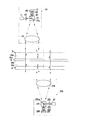
図1に示す大型サンプル測定用干渉計装置(以下、単に「干渉計装置」と称することがある)は、紙面と垂直な方向に移動する、可撓性を有するフィルム状の大型の被検体9の厚みムラをインプロセス計測するものであり、被検体9の一面9a側(図中上方)において下向きに配された複数(本実施形態では7個)の第1の干渉計ヘッド1A〜1Gと、被検体9の他面9b側(図中下方)において上向きに配された複数(本実施形態では6個)の第2の干渉計ヘッド2A〜2Fと、第1の干渉計ヘッド1A〜1Gと被検体9との間に配された第1の基準板3と、第2の干渉計ヘッド2A〜2Fと被検体9との間に配された第2の基準板4と、各干渉計ヘッド1A〜1G,2A〜2Fにより得られた干渉縞画像に基づき縞解析等のための各種演算を行う解析装置5と、解析結果等を表示する画像表示装置6と、解析装置5に対する各種入力を行うための入力装置7とを備えてなる。
A large sample measuring interferometer apparatus (hereinafter sometimes simply referred to as “interferometer apparatus”) shown in FIG. 1 is a flexible film-shaped large subject 9 that moves in a direction perpendicular to the paper surface. Are measured in-process, and a plurality of (seven in this embodiment) first interferometer heads 1A to 1G arranged downward on one surface 9a side (upper side in the figure) of the subject 9 A plurality (six in the present embodiment) of second interferometer heads 2A to 2F and first interferometer heads 1A to 1G arranged upward on the
上記第1の干渉計ヘッド1A〜1Gは、被検体9の一面9a側から、該被検体9の被測定領域S(図2に1点鎖線で示す長方形内の領域)の一部を含む第1領域P1〜P7(図2に実線で示す円内の各領域)に対してそれぞれ測定光を照射し、該第1領域P1〜P7からの戻り光と基準光との光干渉により該第1領域P1〜P7の透過波面情報を担持した干渉縞画像(第1干渉縞画像)をそれぞれ得るように構成されている。 The first interferometer heads 1 </ b> A to 1 </ b> G include a part of a measurement area S (area within a rectangle indicated by a one-dot chain line in FIG. 2) of the subject 9 from the one surface 9 a side of the subject 9. One region P 1 to P 7 (each region in a circle indicated by a solid line in FIG. 2) is irradiated with measurement light, and optical interference between the return light from the first region P 1 to P 7 and the reference light Thus, an interference fringe image (first interference fringe image) carrying transmission wavefront information of the first regions P 1 to P 7 is obtained.
一方、上記第2の干渉計ヘッド2A〜2Fは、被検体9の他面9b側から、上記被測定領域Sの他の一部を含む第2領域Q1〜Q6(図2に破線で示す円内の各領域)に対してそれぞれ測定光を照射し、該第2領域Q1〜Q6からの戻り光と基準光との光干渉により該第2領域Q1〜Q6の透過波面情報を担持した干渉縞画像(第2干渉縞画像)をそれぞれ得るように構成されている。
On the other hand, the second interferometer heads 2A to 2F are second regions Q 1 to Q 6 including other part of the measurement region S from the
第1の干渉計ヘッド1A〜1Gおよび第2の干渉計ヘッド2A〜2Fは、図2に示すように、互いに隣接する第1領域と第2領域(例えば、第1領域P1と第2領域Q1や第1領域P4と第2領域Q4)とが一部重なり合うように、かつ各々の第1領域1A〜1Gおよび第2領域2A〜2Fにより被測定領域Sを包含し得るように、図1に示すようにそれぞれ必要な数だけ配置されている。
As shown in FIG. 2, the first interferometer heads 1 </ b> A to 1 </ b> G and the second interferometer heads 2 </ b> A to 2 </ b> F have a first region and a second region (for example, a first region P 1 and a second region) Q 1 and the first region P 4 and the second region Q 4 ) partially overlap each other, and the measurement region S can be included by each of the first regions 1A to 1G and the
ここで、第1の干渉計ヘッド1A〜1Gおよび第2の干渉計ヘッド2A〜2Fの構成について、より詳細に説明する。各々の第1の干渉計ヘッド1A〜1Gは互いに同様の構成を有しており、各々の第2の干渉計ヘッド2A〜2Fも互いに同様の構成を有しているので、以下では図3に基づき第1の干渉計ヘッド1Aと第2の干渉計ヘッド2Aを例にとって説明する。図3は第1の干渉計ヘッドおよび第2の干渉計ヘッドの概略構成図である。
Here, the configuration of the first interferometer heads 1A to 1G and the second interferometer heads 2A to 2F will be described in more detail. Each of the first interferometer heads 1A to 1G has the same configuration, and each of the second interferometer heads 2A to 2F has the same configuration. Based on the first interferometer head 1A and the
図3に示すように、第1の干渉計ヘッド1Aは、光源11、ビーム径拡大用の発散レンズ12、ビームスプリッタ13、コリメータレンズ14、第1の検光手段としての第1検光子15、結像レンズ16、およびCCDやCMOS等の撮像素子18を備えた撮像カメラ被検体17を備えてなる。上記光源11から出力される光束は、所定の振動面を持つ直線偏光とされており、上記第1検光子15は光源11から出力される直線偏光は透過し、該直線偏光の振動面と直交する振動面を持つ直線偏光(後述の光源21から出力された直線偏光)は遮断するように構成されている。また、上記光源11は、パルスレーザ光源またはビームチョッパ等の機構を備えた光源であり、光源11から出力される光束は、発光期間が短いパルス光とされている。
As shown in FIG. 3, the first interferometer head 1A includes a light source 11, a diverging
一方、第2の干渉計ヘッド2Aは、光源21、ビーム径拡大用の発散レンズ22、ビームスプリッタ23、コリメータレンズ24、第2の検光手段としての第2検光子25、結像レンズ26、およびCCDやCMOS等の撮像素子28を備えた撮像カメラ被検体27を備えてなる。上記光源21から出力される光束は、上記光源11から出力される直線偏光の振動面と直交する振動面を持つ直線偏光とされており、上記第2検光子25は光源21から出力される直線偏光は透過し、該直線偏光の振動面と直交する振動面を持つ直線偏光(前述の光源11から出力された直線偏光)は遮断するように構成されている。また、この光源21は、パルスレーザ光源またはビームチョッパ等の機構を備えた光源であり、光源21から出力される光束は、発光期間が短いパルス光とされている。
On the other hand, the
上記第1の干渉計ヘッド1Aにおいて、光源11から出力された直線偏光からなる光束は、発散レンズ12を透過してビームスプリッタ13に入射し、該ビームプリッタ13の光束分岐面13aにおいて図中下方に反射され、さらにコリメータレンズ14により平行光とされ、測定光として被検体9に向けて出力される。
In the first interferometer head 1A, the light beam composed of linearly polarized light output from the light source 11 passes through the diverging
出力された測定光の一部は、第1の基準板3の基準面3aにおいて反射されて基準光とされ、その余の測定光は第1の基準板3を透過して被検体9の第1領域P1(図2参照)に照射される。照射された測定光は、被検体9を透過した後、その一部が第2の基準板4の基準面4a(第2の反射平面として機能する)において反射され、さらに被検体9および第1の基準板3を透過して第1の干渉計ヘッド1Aに入射する戻り光となる。この戻り光と上記基準光との干渉光が、コリメータレンズ14、ビームスプリッタ13、第1検光子15および結像レンズ16を透過して撮像素子18上に結像され、被検体9の上記第1領域P1に関する透過波面情報を担持した第1干渉縞画像が撮像カメラ17により撮像される。
A part of the output measurement light is reflected by the
一方、上記第2の干渉計ヘッド2Aにおいて、光源21から出力された直線偏光からなる光束は、発散レンズ22を透過してビームスプリッタ23に入射し、該ビームプリッタ23の光束分岐面23aにおいて図中上方に反射され、さらにコリメータレンズ24により平行光とされ、測定光として被検体9に向けて出力される。
On the other hand, in the
出力された測定光の一部は、第2の基準板4の基準面4aにおいて反射されて基準光とされ、その余の測定光は第2の基準板4を透過して被検体9の第2領域Q1(図2参照)に照射される。照射された測定光は、被検体9を透過した後、その一部が第1の基準板3の基準面3a(第1の反射平面として機能する)において反射され、さらに被検体9および第2の基準板4を透過して第2の干渉計ヘッド2Aに入射する戻り光となる。この戻り光と上記基準面4aからの基準光との干渉光が、コリメータレンズ24、ビームスプリッタ23、第2検光子25および結像レンズ26を透過して撮像素子28上に結像され、被検体9の上記第2領域Q1に関する透過波面情報を担持した第2干渉縞画像が撮像カメラ27により撮像される。
A part of the output measurement light is reflected by the
なお、上記第1干渉縞画像と上記第2干渉縞画像とは、互いに同じタイミングで略同時に撮像される。第1領域P1と第2領域Q1とは互いに一部重複しているので、第1の干渉計ヘッド1Aからの測定光の一部は第2の干渉計ヘッド2Aに入射し、第2の干渉計ヘッド2Aからの測定光の一部は第1の干渉計ヘッド1Aに入射することになるが、各々の測定光は第2検光子25および第1検光子15によりそれぞれ遮断されるため、第1干渉縞画像および第2干渉縞画像の撮像に影響を及ぼすことはない。また、測定光の一部は、被検体9の一面9aおよび他面9bにおいて反射されるが、図1,3に示すように第1および第2の基準板3,4を被検体9に対して相対的に傾けて配置することにより、被検体9からの反射光が第1および第2の干渉計ヘッド1A,2Aに戻ることが防止される。
Note that the first interference fringe image and the second interference fringe image are captured substantially simultaneously at the same timing. Since the first region P 1 and the second region Q 1 partly overlap each other, the part of the measurement light from the first interferometer head 1A enters the
さらに、上述の第1の基準板3および第2の基準板4はそれぞれ平行平板状に形成されているが、各々の裏面からの反射光が各干渉計ヘッドに入射しないように、各々の裏面には、ウェッジを付けたり反射防止コート処理を施したりしておくことが好ましい。
Further, although the
以上の説明は、第1干渉計ヘッド1Aと第2の干渉計ヘッド2Aに関するものであるが、他の第1干渉計ヘッド1B〜1Gおよび他の第2の干渉計ヘッド2B〜2Fについても同様である。すなわち、第1の干渉計ヘッド1A〜1Gにより、第1領域P1〜P7の透過波面情報を担持した各第1干渉縞画像が、第2の干渉計ヘッド2A〜2Fにより、第2領域Q1〜Q6の透過波面情報を担持した各第2干渉縞画像が、それぞれ略同時に撮像される。
The above description relates to the first interferometer head 1A and the
撮像された各々の第1干渉縞画像および第2干渉縞画像は、図1に示す解析装置5に入力され、これら第1および第2干渉縞画像に基づき、上記第1領域P1〜P7および上記第2領域Q1〜Q6の各透過波面情報がそれぞれ解析される。そして、各透過波面情報に関する各々の解析結果に対して開口合成の処理を施すことにより、上記被測定領域S全域に亘る被検体9の厚みムラが求められる。
Each captured first interference fringe image and second interference fringe image are input to the
なお、開口合成の具体的な処理については、前掲の特許文献3〜5等に記載されている種々の手法を適用することが可能である。また、本実施形態では、被検体9の屈折率が被検体9の各部において一定(屈折率分布が無い)とみなし、上記各透過波面情報により被検体9の厚みムラを求めている。一方、被検体9の厚みが被検体9の各部において一定(厚みムラが無い)とみなせる場合には、上記各透過波面情報により被検体9の屈折率分布を求めることができる。
Note that various methods described in
また、各透過波面情報の解析処理については、「光学」第13巻第1号(1984年2月)第55頁〜第65頁の「サブフリンジ干渉計測基礎論」に記載されているフーリエ変換法を適用することができる。このフーリエ変換法は、空間キャリア周波数が重畳された縞画像をフーリエ変換し、周波数領域にて空間キャリア周波数を除去した後、逆フーリエ変換して位相解析を行うものであり、本実施形態では、例えば、第1の基準板3と第2の基準板4との間に相対的な傾きを与えることにより、各々の第1干渉縞画像および第2干渉縞画像に空間キャリア周波数を重畳させることが可能となる。フーリエ変換法を適用することにより、移動する被検体9に対してもサブフリンジ計測を行うことが可能となり、被検体9の厚みムラをより高精度に求めることが可能となる。
The analysis process of each transmitted wavefront information is Fourier transform described in “Sub-Fringe Interferometry Basics” on pages 55 to 65 of “Optics” Vol. 13 No. 1 (February 1984). The law can be applied. This Fourier transform method is to perform a Fourier transform on the fringe image on which the spatial carrier frequency is superimposed, remove the spatial carrier frequency in the frequency domain, and then perform an inverse Fourier transform to perform phase analysis. For example, by providing a relative inclination between the
以上、本発明に係る大型サンプル測定用干渉計装置の一実施形態について説明したが、本発明はかかる実施形態に限定されるものではなく、種々に態様を変更することが可能である。 As mentioned above, although one Embodiment of the interferometer apparatus for large sample measurement which concerns on this invention was described, this invention is not limited to this Embodiment, A various aspect can be changed.
例えば、第1の干渉計ヘッドから出力される測定光と第2の干渉計ヘッドから出力される測定光とを、波長が互いに異なるように構成し、第1の干渉計ヘッドにおいて、該第1の干渉計ヘッドから出力される測定光は通過させ、第2の干渉計ヘッドから出力される測定光は遮断する第1の波長選択手段を備えるとともに、第2の干渉計ヘッドにおいて、該第2の干渉計ヘッドから出力される測定光は通過させ、第1の干渉計ヘッドから出力される測定光は遮断する第2の波長選択手段を備えるようにしてもよい。 For example, the measurement light output from the first interferometer head and the measurement light output from the second interferometer head are configured to have different wavelengths, and the first interferometer head has the first interferometer head. The first interferometer head includes first wavelength selection means for allowing the measurement light output from the second interferometer head to pass therethrough and blocking the measurement light output from the second interferometer head. Measurement light output from the interferometer head may be provided, and second wavelength selection means for blocking measurement light output from the first interferometer head may be provided.
具体的には、図3に示す態様において、光源11からの出力光の波長と、光源21からの出力光の波長とが互いに異なるようする。また、第1検光子15に替えて、光源11からの出力光の波長域は透過し光源21からの出力光の波長域は遮断するような第1波長選択フィルタを設置するとともに、第2検光子25に替えて、光源21からの出力光の波長域は透過し光源11からの出力光の波長域は遮断するような第2波長選択フィルタを設置するようにする。
Specifically, in the embodiment shown in FIG. 3, the wavelength of the output light from the light source 11 and the wavelength of the output light from the
また、上記実施形態は、被検体が移動する場合に好適であるが、被検体が移動しない場合には、第1の干渉計ヘッドから出力される測定光が、第1干渉縞画像の露光期間内でかつ第2干渉縞画像の露光期間外に設定された第1発光期間のみ出力されるように構成するとともに、第2の干渉計ヘッドから出力される測定光が、第2干渉縞画像の露光期間内でかつ第1干渉縞画像の露光期間外に設定された第2発光期間のみ出力されるように構成してもよい。この場合、光源11,21からの各出力光を直線偏光としたり、互いに波長が異なるようにしたりする必要はなく、また、第1および第2検光子15,25や第1および第2波長選択フィルタを設置する必要もない。このため、第1および第2の測定ヘッドの構成を簡易にすることができる。
The above embodiment is suitable when the subject moves. However, when the subject does not move, the measurement light output from the first interferometer head is used for the exposure period of the first interference fringe image. And the measurement light output from the second interferometer head is configured to output only the first light emission period set outside the exposure period of the second interference fringe image. It may be configured to output only the second light emission period set within the exposure period and outside the exposure period of the first interference fringe image. In this case, it is not necessary to make each output light from the
また、第1の干渉計ヘッドおよび第2の干渉計ヘッドから出力される各測定光を、被検体の厚みの光学距離の2倍よりも短い可干渉距離を有する低可干渉光とし、第1の干渉計ヘッドおよび第2の干渉計ヘッドにおいて、光源から出力された低可干渉光を2光束に分岐し、該2光束の一方を他方に対して所定の光路長分迂回させた後に1光束に再合波するパスマッチ経路部を備えるようにしてもよい。そして、パスマッチ経路部において、上記所定の光路長を調整することにより、被検体の一面側および他面側からの各反射波面情報を得るとともに、解析手段において各反射波面情報を解析し、各々の解析結果に対して開口合成の処理を施すことにより、被測定領域における被検体の一面側および他面側の各形状を求めるようにする。 Each measurement light output from the first interferometer head and the second interferometer head is a low coherence light having a coherence distance shorter than twice the optical distance of the thickness of the subject, In the interferometer head and the second interferometer head, the low coherent light output from the light source is branched into two light beams, and one of the two light beams is detoured by a predetermined optical path length with respect to the other light beam. May be provided with a path match route section for recombining. Then, in the path match path section, by adjusting the predetermined optical path length, each reflected wavefront information from the one side and the other side of the subject is obtained, and each reflected wavefront information is analyzed by the analyzing means, By performing aperture synthesis processing on the analysis result, the shapes of the one surface side and the other surface side of the subject in the measurement region are obtained.
具体的には、図3に示す態様において、第1の干渉計ヘッド1Aの光源11と拡散レンズ12との間、および第2の干渉計ヘッド2Aの光源21と拡散レンズ22との間に、それぞれパスマッチ経路部を設ける。また、第1および第2の基準板3,4を被検体9に対し略平行となるように配置する。
Specifically, in the embodiment shown in FIG. 3, between the light source 11 and the
そして、被検体9の一面9aの形状を測定する場合、第1の干渉計ヘッド1Aにおいては、該第1の干渉計ヘッド1Aから出力された測定光のうち、第1の基準板3の基準面3aで反射される基準光と、該第1の基準板3を透過した後に被検体9の一面9aで反射され、さらに第1の基準板3を透過する戻り光との光干渉だけが生じるように、パスマッチ経路部において光路長調整を行う。そして、第1領域P1における一面9a側からの反射波面情報を担持した干渉縞画像(第3干渉縞画像)を撮像する。また、第2の干渉計ヘッド2Aにおいては、該第2の干渉計ヘッド2Aから出力された測定光のうち、第2の基準板4の基準面4aで反射される基準光と、該第2の基準板4を透過した後に被検体9の一面9aで反射され、さらに第2の基準板4を透過する戻り光との光干渉だけが生じるように、パスマッチ経路部において光路長調整を行う。そして、第2領域Q1における一面9a側からの反射波面情報を担持した干渉縞画像(第5干渉縞画像)を撮像する。
When measuring the shape of the one surface 9a of the subject 9, the first interferometer head 1A uses the reference of the
一方、被検体9の他面9bの形状を測定する場合、第1の干渉計ヘッド1Aにおいては、該第1の干渉計ヘッド1Aから出力された測定光のうち、第1の基準板3の基準面3aで反射される基準光と、該第1の基準板3を透過した後に被検体9の他面9bで反射され、さらに第1の基準板3を透過する戻り光との光干渉だけが生じるように、パスマッチ経路部において光路長調整を行う。そして、第1領域P1における他面9b側からの反射波面情報を担持した干渉縞画像(第4干渉縞画像)を撮像する。また、第2の干渉計ヘッド2Aにおいては、該第2の干渉計ヘッド2Aから出力された測定光のうち、第2の基準板4の基準面4aで反射される基準光と、該第2の基準板4を透過した後に被検体9の他面9bで反射され、さらに第2の基準板4を透過する戻り光との光干渉だけが生じるように、パスマッチ経路部において光路長調整を行う。そして、第2領域Q1における他面9b側からの反射波面情報を担持した干渉縞画像(第6干渉縞画像)を撮像する。
On the other hand, when measuring the shape of the
さらに、解析手段において、上記第3干渉縞画像および上記第5干渉縞画像に基づき第1領域P1および第2領域Q1における一面9a側からの各反射波面情報を解析する。そして、各々の解析結果に対して開口合成の処理を施すことにより、第1領域P1および第2領域Q1に亘る被検体9の一面9a側の形状を求める。また、上記第4干渉縞画像および上記第6干渉縞画像に基づき第1領域P1および第2領域Q1における他面9b側からの反射波面情報を解析し、各々の解析結果に対して開口合成の処理を施すことにより、第1領域P1および第2領域Q1に亘る被検体9の他面9b側の形状を求めるようにする。
Furthermore, the analysis means analyzes each reflected wavefront information from the third interference fringe image and the first region P 1 and the second one surface 9a side of the region Q 1 on the basis of the fifth interference fringe image. Then, by performing the processing of the aperture synthesis for each of the analysis results to determine the one surface 9a side of the shape of the first region P 1 and the second region Q subject 9 across one. Furthermore, analyzes the reflected wavefront information from the
なお、上記パスマッチ経路部の具体的態様としては、特開平9−21606号公報や特開2005−274236号公報に記載されているものを適用することが可能である。 In addition, as a specific aspect of the path match path part, those described in Japanese Patent Application Laid-Open Nos. 9-21606 and 2005-274236 can be applied.
また、他の態様として、第1の干渉計ヘッドおよび第2の干渉計ヘッドから出力される各測定光を、単一縦モードのレーザ光を発振する波長走査が可能な波長変調光源からのレーザ光とすることも可能である。そして、第1の干渉計ヘッドおよび第2の干渉計ヘッドにおいて、上記レーザ光を、干渉光を受光する素子の1光蓄積期間に対し十分短い周期で複数の波長に変調することにより、第1領域および第2領域における被検体の一面側および他面側からの各反射波面情報を得るとともに、解析手段において、被検体の一面側および他面側からの各反射波面情報を解析し、各々の解析結果に対して開口合成の処理を施すことにより、被測定領域における被検体の一面側および他面側の各形状を求めるようにしてもよい。 As another aspect, each measurement light output from the first interferometer head and the second interferometer head is converted from a laser from a wavelength-modulated light source capable of wavelength scanning to oscillate a single longitudinal mode laser beam. It can also be light. Then, in the first interferometer head and the second interferometer head, the laser light is modulated into a plurality of wavelengths at a sufficiently short period with respect to one light accumulation period of the element that receives the interference light. In addition to obtaining each reflected wavefront information from one side and the other side of the subject in the region and the second region, the analysis unit analyzes each reflected wavefront information from the one side and the other side of the subject, You may make it obtain | require each shape of the one surface side of the to-be-examined object in a to-be-measured area | region, and an other surface side by performing an aperture synthesis process with respect to an analysis result.
この態様のものは、波長変調光源からのレーザ光を波長走査することにより、上述のパスマッチ経路部を備えたものと同様に、所定面からの戻り光のみが基準光と干渉するように調整するもので、具体的には、図3に示す態様において、第1の干渉計ヘッド1Aの光源11および第2の干渉計ヘッド2Aの光源21を、上述の波長変調光源とすればよい。なお、単一縦モードのレーザ光を発振する波長走査が可能な波長変調光源、および波長走査の具体的態様としては、特許第3621693号公報に記載されているものを適用することが可能である。
In this embodiment, the laser light from the wavelength-modulated light source is wavelength-scanned and adjusted so that only the return light from the predetermined surface interferes with the reference light, similar to the above-described one having the path match path section. Specifically, in the embodiment shown in FIG. 3, the light source 11 of the first interferometer head 1A and the
また、上述のパスマッチ経路部を備えた態様のもの、および波長変調光源を備えた態様のものにおいては、求められた被検体の一面側の形状と他面側の形状、および被検体の透過波面情報により得られる厚みムラに基づき、被測定領域における被検体の所定の厚みに対応した屈折率分布を求めることができる。なお、被検体の所定の厚みに対応した屈折率分布を求める具体的手法としては、上記特開2005−274236号公報に記載されているものを適用することが可能である。 Further, in the aspect provided with the above-described path match path portion and the aspect provided with the wavelength modulation light source, the obtained shape of the one surface side and the other surface side of the subject, and the transmitted wavefront of the subject Based on the thickness unevenness obtained from the information, a refractive index distribution corresponding to a predetermined thickness of the subject in the measurement region can be obtained. In addition, as a specific method for obtaining a refractive index distribution corresponding to a predetermined thickness of the subject, one described in the above Japanese Patent Application Laid-Open No. 2005-274236 can be applied.
また、第1の干渉計ヘッドおよび第2の干渉計ヘッドの個数(最低限1基ずつは必要)や配列の仕方は、設定された被測定領域の大きさや形状等に応じて適宜変更することができる。例えば、第1の干渉計ヘッドおよび第2の干渉計ヘッドを縦横アレイ状に配置することも可能である。 Also, the number of first interferometer heads and the second interferometer heads (at least one is necessary) and the arrangement method should be changed as appropriate according to the size and shape of the set measurement area. Can do. For example, the first interferometer head and the second interferometer head can be arranged in a vertical and horizontal array.
なお、上述した実施形態においては、被検体9として、可撓性を有するフィルムを例示しているが、本発明は、液晶パネル等の可撓性を有しない板状の被検体に対しても適用し得る。 In the above-described embodiment, a flexible film is exemplified as the subject 9, but the present invention is also applicable to a plate-like subject having no flexibility such as a liquid crystal panel. Applicable.
1A〜1G 第1の干渉計ヘッド
2A〜2F 第2の干渉計ヘッド
3 第1の基準板
3a (第1の基準板の)基準面
4 第2の基準板
4a (第2の基準板の)基準面
5 解析装置
6 画像表示装置
7 入力装置
9 被検体
11,21 光源
12,22 発散レンズ
13,23 ビームスプリッタ
13a,23a 光束分岐面
14,24 コリメータレンズ
15 第1検光子
16,26 結像レンズ
17,27 撮像カメラ
18,28 撮像素子
19 傾き調整ステージ
25 第2検光子
S 被測定領域
P1〜P7 第1領域
Q1〜Q6 第2領域
1A to 1G
Claims (9)
前記第1の干渉計ヘッドは、前記一面側から前記被検体の被測定領域の一部を含む第1領域に対して測定光を照射し、前記被検体を透過して前記第2の反射平面で反射され、再び該被検体を透過して当該第1の干渉計ヘッドに戻る戻り光と、当該第1の干渉計ヘッドの基準光との光干渉により前記第1領域の透過波面情報を担持した第1干渉縞画像を得るように構成され、
前記第2の干渉計ヘッドは、前記他面側から前記被検体の被測定領域の他の一部を含む第2領域に対して測定光を照射し、前記被検体を透過して前記第1の反射平面で反射され、再び該被検体を透過して当該第2の干渉計ヘッドに戻る戻り光と、当該第2の干渉計ヘッドの基準光との光干渉により前記第2領域の透過波面情報を担持した第2干渉縞画像を得るように構成され、
前記第1の干渉計ヘッドおよび前記第2の干渉計ヘッドは、互いに隣接する前記第1領域と前記第2領域とが一部重なり合うように、かつ各々の前記第1領域および前記第2領域により前記被測定領域を包含し得るように、それぞれ所定数配置され、
前記解析手段は、前記第1干渉縞画像および前記第2干渉縞画像に基づき前記第1領域および前記第2領域の各透過波面情報をそれぞれ解析するとともに、前記第1領域および前記第2領域の各透過波面情報に関する各々の解析結果に対して開口合成の処理を施すことにより、前記被測定領域における前記被検体の厚みムラを求めるように構成されている、ことを特徴とする大型サンプル測定用干渉計装置。 A first interferometer head disposed on one side of the sheet-like subject; a second interferometer head disposed on the other side of the subject; and the subject and the first interferometer head A second reflection plane disposed between the subject and the second interferometer head, and an analysis means for analyzing the interference fringe image. An interferometer device comprising:
The first interferometer head irradiates measurement light to a first region including a part of the measurement region of the subject from the one surface side, transmits the subject, and transmits the second reflection plane. The transmitted wavefront information of the first region is carried by the optical interference between the return light that is reflected by the reflected light, returns through the subject, and returns to the first interferometer head, and the reference light from the first interferometer head. Configured to obtain a first interference fringe image,
The second interferometer head irradiates measurement light to a second region including another part of the measurement region of the subject from the other surface side, passes through the subject, and transmits the first region. The transmitted wavefront of the second region is reflected by the optical interference between the return light that is reflected by the reflection plane and returns to the second interferometer head through the subject and the reference light of the second interferometer head. Configured to obtain a second interference fringe image carrying information;
The first interferometer head and the second interferometer head are arranged such that the first region and the second region adjacent to each other partially overlap each other and each of the first region and the second region. A predetermined number of each is arranged so as to include the measurement area,
The analysis means analyzes the transmitted wavefront information of the first area and the second area based on the first interference fringe image and the second interference fringe image, respectively, and the analysis of the first area and the second area For large sample measurement, characterized in that it is configured to obtain thickness unevenness of the subject in the measurement region by performing aperture synthesis processing on each analysis result regarding each transmitted wavefront information Interferometer device.
前記第1の干渉計ヘッドは、該第1の干渉計ヘッドから出力される直線偏光は通過させ、前記第2の干渉計ヘッドから出力される直線偏光は遮断する第1の検光手段を備え、
前記第2の干渉計ヘッドは、該第2の干渉計ヘッドから出力される直線偏光は通過させ、前記第1の干渉計ヘッドから出力される直線偏光は遮断する第2の検光手段を備えている、ことを特徴とする請求項1記載の大型サンプル測定用干渉計装置。 The measurement light output from the first interferometer head and the measurement light output from the second interferometer head are composed of linearly polarized light whose polarization directions are orthogonal to each other.
The first interferometer head includes first light detecting means for passing linearly polarized light output from the first interferometer head and blocking linearly polarized light output from the second interferometer head. ,
The second interferometer head includes second light detecting means for passing linearly polarized light output from the second interferometer head and blocking linearly polarized light output from the first interferometer head. The interferometer apparatus for measuring a large sample according to claim 1, wherein
前記第1の干渉計ヘッドは、該第1の干渉計ヘッドから出力される測定光は通過させ、前記第2の干渉計ヘッドから出力される測定光は遮断する第1の波長選択手段を備え、
前記第2の干渉計ヘッドは、該第2の干渉計ヘッドから出力される測定光は通過させ、前記第1の干渉計ヘッドから出力される測定光は遮断する第2の波長選択手段を備えている、ことを特徴とする請求項1記載の大型サンプル測定用干渉計装置。 The measurement light output from the first interferometer head and the measurement light output from the second interferometer head are configured to have different wavelengths.
The first interferometer head includes first wavelength selection means for allowing measurement light output from the first interferometer head to pass therethrough and blocking measurement light output from the second interferometer head. ,
The second interferometer head includes second wavelength selection means for allowing measurement light output from the second interferometer head to pass therethrough and blocking measurement light output from the first interferometer head. The interferometer apparatus for measuring a large sample according to claim 1, wherein
前記第2の干渉計ヘッドから出力される測定光は、該第2の干渉計ヘッドにおける前記第2干渉縞画像の露光期間内で、かつ前記第1の干渉計における前記第1干渉縞画像の露光期間外に設定された第2発光期間のみ出力されるように構成されている、ことを特徴とする請求項1記載の大型サンプル測定用干渉計装置。 The measurement light output from the first interferometer head is within the exposure period of the first interference fringe image in the first interferometer head and the second interference fringe image in the second interferometer. Configured to output only the first light emission period set outside the exposure period,
The measurement light output from the second interferometer head is within the exposure period of the second interference fringe image in the second interferometer head and the first interference fringe image in the first interferometer. 2. The interferometer apparatus for measuring a large sample according to claim 1, wherein the interferometer apparatus is configured to output only the second light emission period set outside the exposure period.
前記第1の干渉計ヘッドおよび前記第2の干渉計ヘッドは、光源から出力された前記低可干渉光を2光束に分岐し、該2光束の一方を他方に対して所定の光路長分迂回させた後に1光束に再合波するパスマッチ経路部を備え、該パスマッチ経路部において、前記所定の光路長を調整することにより、前記第1領域および前記第2領域における前記一面側および前記他面側からの各反射波面情報を得るように構成され、
前記解析手段は、前記一面側および前記他面側からの各反射波面情報を解析し、各々の解析結果に対して開口合成の処理を施すことにより、前記被測定領域における前記被検体の前記一面側および前記他面側の各形状を求めるように構成されている、ことを特徴とする請求項1〜4のいずれか1項記載の大型サンプル測定用干渉計装置。 Each measurement light output from the first interferometer head and the second interferometer head is a low coherence light having a coherence distance shorter than twice the optical distance of the thickness of the subject,
The first interferometer head and the second interferometer head branch the low coherence light output from a light source into two light beams, and bypass one of the two light beams for a predetermined optical path length with respect to the other. A path match path that re-combines into one light beam after adjusting the first optical path length in the first area and the second area by adjusting the predetermined optical path length in the path match path section. Configured to obtain each reflected wavefront information from the side,
The analysis means analyzes each reflected wavefront information from the one surface side and the other surface side, and performs an aperture synthesis process on each analysis result, whereby the one surface of the subject in the measurement region The interferometer apparatus for measuring a large sample according to any one of claims 1 to 4, wherein the interferometer apparatus is configured to obtain respective shapes on the side and the other surface side.
前記第1の干渉計ヘッドおよび前記第2の干渉計ヘッドは、前記レーザ光を、前記干渉光を受光する素子の1光蓄積期間に対し十分短い周期で複数の波長に変調することにより、前記第1領域および前記第2領域における前記一面側および前記他面側からの各反射波面情報を得るように構成され、
前記解析手段は、前記一面側および前記他面側からの各反射波面情報を解析し、各々の解析結果に対して開口合成の処理を施すことにより、前記被測定領域における前記被検体の前記一面側および前記他面側の各形状を求めるように構成されている、ことを特徴とする請求項1〜4のいずれか1項記載の大型サンプル測定用干渉計装置。 Each measurement light output from the first interferometer head and the second interferometer head is a laser beam from a wavelength-modulated light source capable of wavelength scanning to oscillate a single longitudinal mode laser beam,
The first interferometer head and the second interferometer head modulate the laser light into a plurality of wavelengths with a sufficiently short period with respect to one light accumulation period of an element that receives the interference light. It is configured to obtain each reflected wavefront information from the one surface side and the other surface side in the first region and the second region,
The analysis means analyzes each reflected wavefront information from the one surface side and the other surface side, and performs an aperture synthesis process on each analysis result, whereby the one surface of the subject in the measurement region The interferometer apparatus for measuring a large sample according to any one of claims 1 to 4, wherein the interferometer apparatus is configured to obtain respective shapes on the side and the other surface side.
The analysis means is configured to analyze an interference fringe image using a Fourier transform method that performs phase analysis based on a fringe image on which a spatial carrier frequency is superimposed. The interferometer device for large sample measurement according to any one of -8.
Priority Applications (1)
| Application Number | Priority Date | Filing Date | Title |
|---|---|---|---|
| JP2007247884A JP2009079933A (en) | 2007-09-25 | 2007-09-25 | Interferometer device for measuring large-sized sample |
Applications Claiming Priority (1)
| Application Number | Priority Date | Filing Date | Title |
|---|---|---|---|
| JP2007247884A JP2009079933A (en) | 2007-09-25 | 2007-09-25 | Interferometer device for measuring large-sized sample |
Publications (1)
| Publication Number | Publication Date |
|---|---|
| JP2009079933A true JP2009079933A (en) | 2009-04-16 |
Family
ID=40654800
Family Applications (1)
| Application Number | Title | Priority Date | Filing Date |
|---|---|---|---|
| JP2007247884A Abandoned JP2009079933A (en) | 2007-09-25 | 2007-09-25 | Interferometer device for measuring large-sized sample |
Country Status (1)
| Country | Link |
|---|---|
| JP (1) | JP2009079933A (en) |
Cited By (2)
| Publication number | Priority date | Publication date | Assignee | Title |
|---|---|---|---|---|
| JP2011053176A (en) * | 2009-09-04 | 2011-03-17 | Sony Corp | Inspection device and inspection method |
| JP2013072860A (en) * | 2011-09-29 | 2013-04-22 | Toppan Printing Co Ltd | Thickness measuring method and measuring apparatus |
Citations (12)
| Publication number | Priority date | Publication date | Assignee | Title |
|---|---|---|---|---|
| JPH01235806A (en) * | 1988-03-15 | 1989-09-20 | Mitsubishi Electric Corp | Optical measuring instrument |
| JPH03115911A (en) * | 1989-09-29 | 1991-05-16 | Anritsu Corp | Thickness measuring instrument for transparent body |
| JPH03118406A (en) * | 1989-09-30 | 1991-05-21 | Anritsu Corp | Laser thickness gauge |
| JPH07103724A (en) * | 1993-09-30 | 1995-04-18 | Toppan Printing Co Ltd | Apparatus for measuring film thickness and apparatus for forming film in vacuum |
| JP2000275022A (en) * | 1999-03-29 | 2000-10-06 | Fuji Photo Optical Co Ltd | Apparatus for measuring double face shape and thickness irregularity |
| JP2001066121A (en) * | 1999-08-26 | 2001-03-16 | Kobe Steel Ltd | Surface shape measuring device |
| JP2002162214A (en) * | 2000-11-22 | 2002-06-07 | Fuji Photo Optical Co Ltd | Method for measuring wave front shape of large-sized body to be observed by aperture synthesis and measuring wave front shape correction method |
| JP2002236004A (en) * | 2001-02-08 | 2002-08-23 | Dac Engineering Kk | Method and apparatus for measuring thickness of light transmission body |
| JP2003232617A (en) * | 2001-12-07 | 2003-08-22 | Kobe Steel Ltd | Device and method of measuring thickness distribution |
| JP2004037165A (en) * | 2002-07-01 | 2004-02-05 | Fuji Photo Optical Co Ltd | Interferometer device |
| JP2005274236A (en) * | 2004-03-23 | 2005-10-06 | Fujinon Corp | Path-matching path interferometer device |
| JP2006349534A (en) * | 2005-06-16 | 2006-12-28 | Fujinon Corp | Interferometer system and method of optical interferometry for measuring moving body |
-
2007
- 2007-09-25 JP JP2007247884A patent/JP2009079933A/en not_active Abandoned
Patent Citations (12)
| Publication number | Priority date | Publication date | Assignee | Title |
|---|---|---|---|---|
| JPH01235806A (en) * | 1988-03-15 | 1989-09-20 | Mitsubishi Electric Corp | Optical measuring instrument |
| JPH03115911A (en) * | 1989-09-29 | 1991-05-16 | Anritsu Corp | Thickness measuring instrument for transparent body |
| JPH03118406A (en) * | 1989-09-30 | 1991-05-21 | Anritsu Corp | Laser thickness gauge |
| JPH07103724A (en) * | 1993-09-30 | 1995-04-18 | Toppan Printing Co Ltd | Apparatus for measuring film thickness and apparatus for forming film in vacuum |
| JP2000275022A (en) * | 1999-03-29 | 2000-10-06 | Fuji Photo Optical Co Ltd | Apparatus for measuring double face shape and thickness irregularity |
| JP2001066121A (en) * | 1999-08-26 | 2001-03-16 | Kobe Steel Ltd | Surface shape measuring device |
| JP2002162214A (en) * | 2000-11-22 | 2002-06-07 | Fuji Photo Optical Co Ltd | Method for measuring wave front shape of large-sized body to be observed by aperture synthesis and measuring wave front shape correction method |
| JP2002236004A (en) * | 2001-02-08 | 2002-08-23 | Dac Engineering Kk | Method and apparatus for measuring thickness of light transmission body |
| JP2003232617A (en) * | 2001-12-07 | 2003-08-22 | Kobe Steel Ltd | Device and method of measuring thickness distribution |
| JP2004037165A (en) * | 2002-07-01 | 2004-02-05 | Fuji Photo Optical Co Ltd | Interferometer device |
| JP2005274236A (en) * | 2004-03-23 | 2005-10-06 | Fujinon Corp | Path-matching path interferometer device |
| JP2006349534A (en) * | 2005-06-16 | 2006-12-28 | Fujinon Corp | Interferometer system and method of optical interferometry for measuring moving body |
Cited By (2)
| Publication number | Priority date | Publication date | Assignee | Title |
|---|---|---|---|---|
| JP2011053176A (en) * | 2009-09-04 | 2011-03-17 | Sony Corp | Inspection device and inspection method |
| JP2013072860A (en) * | 2011-09-29 | 2013-04-22 | Toppan Printing Co Ltd | Thickness measuring method and measuring apparatus |
Similar Documents
| Publication | Publication Date | Title |
|---|---|---|
| KR101590241B1 (en) | Optical characteristics measuring apparatus, and optical characteristics measuring method | |
| US7990543B1 (en) | Surface characterization based on optical phase shifting interferometry | |
| US10635049B2 (en) | Ellipsometry device and ellipsometry method | |
| KR20100134609A (en) | Apparatus and method for measuring surface topography of an object | |
| CN106461377A (en) | Optical phase measurement method and system | |
| US20140374575A1 (en) | Spatial frequency reproducing apparatus and optical distance measuring apparatus | |
| US20130280798A1 (en) | Distance measurement system and optical resolution improvement apparatus | |
| US20230063843A1 (en) | Method and apparatus for high performance wide field photothermal imaging and spectroscopy | |
| US7561279B2 (en) | Scanning simultaneous phase-shifting interferometer | |
| US9411146B2 (en) | Observation device | |
| JP2001272332A (en) | Angular dispersed light spatial interference tomographic imaging apparatus | |
| JP2006250849A (en) | Optical image measuring method using light coherence tomography apparatus and optical image measuring device | |
| JP5428538B2 (en) | Interfering device | |
| US20220065617A1 (en) | Determination of a change of object's shape | |
| US11248955B2 (en) | Polarization measurement with interference patterns of high spatial carrier frequency | |
| US11892292B2 (en) | Methods and systems of holographic interferometry | |
| EP2535679A1 (en) | Improvements in or relating to interferometry | |
| JP2007298281A (en) | Measuring method and device of surface shape of specimen | |
| JP2009079933A (en) | Interferometer device for measuring large-sized sample | |
| JP3960427B2 (en) | Method and apparatus for simultaneous measurement of surface shape and film thickness distribution of multilayer film | |
| US20110299090A1 (en) | Real-time interferometer | |
| JP2007093288A (en) | Light measuring instrument and light measuring method | |
| JP5518187B2 (en) | Deformation measurement method | |
| JP2018100915A (en) | Phase distribution measurement device, phase distribution measurement method and phase distribution measurement program | |
| CN111033228A (en) | Detection apparatus and detection method |
Legal Events
| Date | Code | Title | Description |
|---|---|---|---|
| A621 | Written request for application examination |
Free format text: JAPANESE INTERMEDIATE CODE: A621 Effective date: 20100415 |
|
| A711 | Notification of change in applicant |
Free format text: JAPANESE INTERMEDIATE CODE: A711 Effective date: 20100621 |
|
| A977 | Report on retrieval |
Effective date: 20110819 Free format text: JAPANESE INTERMEDIATE CODE: A971007 |
|
| A131 | Notification of reasons for refusal |
Free format text: JAPANESE INTERMEDIATE CODE: A131 Effective date: 20110928 |
|
| A762 | Written abandonment of application |
Free format text: JAPANESE INTERMEDIATE CODE: A762 Effective date: 20111118 |