JP2009078675A - Wheel supporting device - Google Patents
Wheel supporting device Download PDFInfo
- Publication number
- JP2009078675A JP2009078675A JP2007249131A JP2007249131A JP2009078675A JP 2009078675 A JP2009078675 A JP 2009078675A JP 2007249131 A JP2007249131 A JP 2007249131A JP 2007249131 A JP2007249131 A JP 2007249131A JP 2009078675 A JP2009078675 A JP 2009078675A
- Authority
- JP
- Japan
- Prior art keywords
- hub
- shaft
- constant velocity
- velocity joint
- outer ring
- Prior art date
- Legal status (The legal status is an assumption and is not a legal conclusion. Google has not performed a legal analysis and makes no representation as to the accuracy of the status listed.)
- Pending
Links
Images


Landscapes
- Mounting Of Bearings Or Others (AREA)
- Rolling Contact Bearings (AREA)
Abstract
Description
この発明は、車輪が取り付けられるハブホイールのハブ軸と、等速ジョイントの外輪とがトルク伝達可能に連結された車輪支持装置に関する。 The present invention relates to a wheel support device in which a hub shaft of a hub wheel to which a wheel is attached and an outer ring of a constant velocity joint are connected so as to be able to transmit torque.
この種の車輪支持装置において、図6に示すように、ハブホイール210と等速ジョイント250とをトルク伝達可能に接続するために、ハブホイール210のハブ軸213の端面と、この端面に突き合わされる等速ジョイント250の外輪260の側壁部261の端面に、相互に噛み合うことでハブホイール210と等速ジョイント250とをトルク伝達する両サイドフェーススプライン218、262が形成されたものがある。
また、このような構造をもつ車輪支持装置において、等速ジョイント250の外輪260の側壁部261の端面から連結ボルト270を突出し、この連結ボルト270の軸部272の先端の雄ねじ部273をハブ軸213の内孔214の一端側(車幅方向中心側)から他端側(車幅方向外側)に向けて挿通し、この雄ねじ部273をハブ軸213の内孔214の他端側に突出させた状態で雄ねじ部273に締付ナット275を締め付けることで、ハブホイール210と等速ジョイント250とを一体状に連結した構造のものがある。
なお、ハブホイールのハブ軸の端面と等速ジョイントの端面にサイドフェーススプラインが形成された車輪支持装置においては、例えば、特許文献1に開示されている。
In the wheel support device having such a structure, the connecting
A wheel support device in which side face splines are formed on the end face of the hub axle of the hub wheel and the end face of the constant velocity joint is disclosed in, for example, Patent Document 1.
ところで、図6に示すような構造をもつ車輪支持装置においては、ハブ軸213の内孔214と連結ボルト270の軸部272との間の環状の隙間によって、ハブホイール210と等速ジョイント250との芯合わせがしづらく、両サイドフェーススプライン218、262の噛み合わせが厄介となる。
また、ハブホイール210と等速ジョイント250とを連結ボルト270と締付ナット275によって一体状に連結した状態において、ハブ軸213の内孔214と連結ボルト270の軸部272との間の環状の隙間によって、ハブホイール210と等速ジョイント250とが相対的に振動したり、あるいは異音を発生することが想定される。
そこで、ハブ軸213の内孔214と連結ボルト270の軸部272とを高精度に加工してハブ軸213の内孔214と連結ボルト270の軸部272とを僅かな隙間をもって嵌合させることが考えられるが、ハブ軸213の内孔214と連結ボルト270の軸部272とを高精度に加工すると、加工コストが高くなると共に、ハブ軸213の内孔214に対する連結ボルト270の軸部272の挿入性が悪化する。
By the way, in the wheel support device having the structure as shown in FIG. 6, the
Further, in a state where the
Therefore, the
この発明の目的は、前記問題点に鑑み、ハブホイールのハブ軸の内孔に連結ボルトの軸部が嵌挿される動作によって、ハブホイールと等速ジョイントとを同一中心線上に位置合わせすることができ、両サイドフェーススプラインを容易に噛み合わせることができる車輪支持装置を提供することである。 In view of the above problems, the object of the present invention is to align the hub wheel and the constant velocity joint on the same center line by the operation of inserting the shaft portion of the connecting bolt into the inner hole of the hub shaft of the hub wheel. It is possible to provide a wheel support device capable of easily engaging both side face splines.
前記目的を達成するために、この発明の請求項1に係る車輪支持装置は、車輪が取り付けられるハブホイールのハブ軸と、等速ジョイントの外輪とがトルク伝達可能に連結された車輪支持装置であって、
前記ハブ軸の端面と、この端面に突き合わされる前記等速ジョイントの外輪の端面には、相互に噛み合うことで前記ハブホイールのハブ軸と前記等速ジョイントの外輪とをトルク伝達可能に接続する両サイドフェーススプラインが形成され、
前記ハブ軸の内孔に前記等速ジョイントの外輪の端面から突出された連結ボルトが挿通され、この連結ボルトの軸部先端部の雄ねじ部に締付ナットが締め付けられることで、前記ハブホイールのハブ軸と等速ジョイントの外輪とが連結され、
前記ハブ軸の内孔の一部には、同内孔の他の部分よりも孔径が小さく、かつ前記連結ボルトの軸部が僅かな隙間をもって嵌挿される小径孔部が形成されていることを特徴とする。
In order to achieve the above object, a wheel support device according to claim 1 of the present invention is a wheel support device in which a hub shaft of a hub wheel to which a wheel is attached and an outer ring of a constant velocity joint are connected so as to be able to transmit torque. There,
The hub shaft of the hub wheel and the outer ring of the constant velocity joint are connected to each other so that torque can be transmitted between the end surface of the hub shaft and the end surface of the outer ring of the constant velocity joint abutted on the end surface. Both side face splines are formed,
A connecting bolt protruding from the end face of the outer ring of the constant velocity joint is inserted into the inner hole of the hub shaft, and a tightening nut is tightened to the male thread portion at the tip of the shaft portion of the connecting bolt. The hub axle and the constant velocity joint outer ring are connected,
A part of the inner hole of the hub shaft is formed with a small-diameter hole part in which the hole diameter is smaller than the other part of the inner hole and the shaft part of the connecting bolt is inserted with a slight gap. Features.
前記構成によると、ハブホイールと等速ジョイントとをトルク伝達可能に一体状に連結する場合、等速ジョイントの外輪の端面から突出された連結ボルトの軸部をハブ軸の内孔の一端側(車幅方向中心側)から他端側(車幅方向外側)に向けて挿通する。
そして、ハブ軸の端面と等速ジョイントの外輪の端面との両サイドフェーススプラインを噛み合わせながら、連結ボルトの軸部先端部の雄ねじ部をハブ軸の内孔の他端側に突出させた状態で雄ねじ部に締付ナットを締め付けることで、ハブホイールと等速ジョイントとをトルク伝達可能に一体状に連結する。
連結ボルトの軸部をハブ軸の内孔の一端側から他端側に向けて挿通する際、ハブ軸の内孔の小径孔部に連結ボルトの軸部を嵌挿させる動作によって、ハブホイールと等速ジョイントとを同一中心線上に正確に位置合わせすることができる。このため、ハブ軸の端面と、等速ジョイントの外輪の端面との両サイドフェーススプラインを容易に噛み合わせることができる。
特に、ハブ軸の内孔の一部に小径孔部を形成することによって、加工コストの増大や連結ボルトの挿入性の悪化を抑制することができると共に、振動、異音等の発生を抑制することができる。
According to the above configuration, when the hub wheel and the constant velocity joint are integrally connected so as to transmit torque, the shaft portion of the connecting bolt protruding from the end surface of the outer ring of the constant velocity joint is connected to one end side of the inner hole of the hub shaft ( It is inserted from the vehicle width direction center side toward the other end side (vehicle width direction outer side).
And the state where the male screw part at the tip part of the shaft part of the connecting bolt protrudes to the other end side of the inner hole of the hub shaft while engaging both side face splines of the end face of the hub shaft and the end face of the outer ring of the constant velocity joint. The hub wheel and the constant velocity joint are integrally connected so that torque can be transmitted by tightening a tightening nut on the male thread portion.
When inserting the shaft portion of the connecting bolt from one end side of the inner hole of the hub shaft toward the other end side, the hub wheel and the hub wheel are moved by inserting the shaft portion of the connecting bolt into the small diameter hole portion of the inner hole of the hub shaft. The constant velocity joint can be accurately aligned on the same center line. For this reason, both side face splines of the end face of the hub shaft and the end face of the outer ring of the constant velocity joint can be easily meshed.
In particular, by forming a small-diameter hole in a part of the inner hole of the hub shaft, it is possible to suppress an increase in processing cost and deterioration of the insertion performance of the connecting bolt, and also suppress the occurrence of vibration, abnormal noise, and the like. be able to.
請求項2に係る車輪支持装置は、請求項1に記載の車輪支持装置であって、
ハブ軸の内孔の内周面には、小径孔部のボルト挿入側に連続し、かつ連結ボルトの軸部先端を挿入案内するテーパ孔状の案内部が形成されていることを特徴とする。
前記構成によると、ハブ軸の内孔の小径孔部に連結ボルトの軸部が挿入される際、小径孔部のボルト挿入側に連続するテーパ孔状の案内部によって、連結ボルトの軸部先端を挿入案内することができ、連結ボルトの挿入性の向上を良好に図ることができる。
A wheel support device according to claim 2 is the wheel support device according to claim 1,
The inner peripheral surface of the inner hole of the hub shaft is formed with a tapered hole-shaped guide portion that is continuous with the bolt insertion side of the small-diameter hole portion and guides and inserts the tip end of the shaft portion of the connecting bolt. .
According to the above configuration, when the shaft portion of the connecting bolt is inserted into the small diameter hole portion of the inner hole of the hub shaft, the tip end of the shaft portion of the connecting bolt is formed by the tapered hole-shaped guide portion continuous to the bolt insertion side of the small diameter hole portion. The insertion of the connecting bolt can be improved satisfactorily.
次に、この発明を実施するための最良の形態を実施例にしたがって説明する。 Next, the best mode for carrying out the present invention will be described with reference to examples.
(実施例1)
この発明の実施例1を図1〜図3にしたがって説明する。
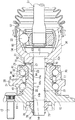
図1はこの発明の実施例1に係る車輪支持装置を示す側断面図である。図2はハブホイールと等速ジョイントとを連結する前の分離状態を示す断面図である。図3はハブホイールのハブ軸の中心部に内孔を形成するための第1、第2テーパ孔部を鍛造によって形成した状態を示す断面図である。
図1に示すように、この実施例1の車輪支持装置は、ハブホイール10と、転がり軸受としての複列のアンギュラ玉軸受20と、等速ジョイント50とを備えて構成されている。
Example 1
A first embodiment of the present invention will be described with reference to FIGS.
1 is a side sectional view showing a wheel support device according to Embodiment 1 of the present invention. FIG. 2 is a cross-sectional view showing a separated state before connecting the hub wheel and the constant velocity joint. FIG. 3 is a cross-sectional view showing a state in which the first and second tapered hole portions for forming the inner hole in the center portion of the hub shaft of the hub wheel are formed by forging.
As shown in FIG. 1, the wheel support device according to the first embodiment includes a
等速ジョイント50は、周知のツェッパー型、バーフィールド型と呼ばれている等速ジョイントが使用されており、駆動軸51の一端に一体状に連結された内輪52と、外輪60と、これら内・外輪52、60の間に配設された複数のボール53と、これら複数のボール53を保持する保持器54を備えて構成されている。
等速ジョイント50の外輪60の側壁部61端面には、サイドフェーススプライン62が形成されている。
また、等速ジョイント50の外輪60の側壁部61の中心部にはハブホイール10と等速ジョイント50とを一体状に連結するための連結ボルト70が突出されている。
As the
A
Further, a connecting
この実施例1において、連結ボルト70は、等速ジョイント50の外輪60と別体をなす頭部71と軸部72とを有する一方、等速ジョイント50の外輪60の側壁部61の中心部には貫通孔63が貫設されている。
そして、等速ジョイント50の外輪60の貫通孔63の内側開口部から連結ボルト70の軸部72が嵌挿され、頭部71の下面が側壁部61の内面に当接する位置まで軸部72の根本部の大径部72aが圧入されることによって、等速ジョイント50の外輪60の側壁部61から連結ボルト70の軸部72が突出されて固定される。連結ボルト70の軸部72の先端部には雄ねじ部73が形成され、この雄ねじ部73には締付ナット75を回り止めするためのかしめ溝74が凹設されている。
In the first embodiment, the connecting
Then, the
図1に示すように、ハブホイール10は、円筒状をなすハブ軸13と、ハブ軸13の一端部寄り外周面に形成されたフランジ11とを一体に有している。そして、フランジ11には、ブレーキロータ(図示しない)を間に挟んで車輪(図示しない)を取り付けるための複数本のハブボルト12が所定ピッチでかつ圧入によって固定されている。
ハブ軸13の外周には、外輪30、内輪21、転動体としての複数の玉41、42及び保持器45、46を備えた複列のアンギュラ玉軸受20が組み付けられている。すなわち、この実施例1において、ハブ軸13はフランジ11側に形成された大径軸部15と、大径軸部15よりも適宜に小径でかつ大径軸部15と段差部をもって連続して形成された小径軸部16とを一体に有している。そして、大径軸部15の外周面に、外輪30の一方の軌道面31に対応する軌道面22が形成されている。
さらに、外輪30の他方の軌道面32に対応する軌道面23が外周面に形成された内輪21がハブ軸13の小径軸部16の外周面に嵌込まれた後、小径軸部16の先端部がかしめられてかしめ部17が形成されることによって、内輪21が段差部とかしめ部17との間に固定されている。
また、外輪30の両軌道面31、32と、ハブ軸13側の両軌道面22、23との間には各複数個の玉41、42と、これら各複数個の玉41、42をそれぞれ保持する保持器45、46が組み付けられる。
また、外輪30の外周面には、車両の懸架装置(図示しない)に支持された車体側部材(ナックル、又はキャリア)にボルトによって取り付けるための固定フランジ35が一体に形成されている。
As shown in FIG. 1, the
A double-row angular ball bearing 20 including an
Further, after the inner ring 21 in which the
Further, a plurality of
In addition, a
図1に示すように、ハブ軸13の端面、この実施例1ではハブ軸13のかしめ部17の端面には、この端面に突き合わされる等速ジョイント50の外輪60の側壁部61端面のサイドフェーススプライン62に噛み合うサイドフェーススプライン18が形成されている。
また、ハブ軸13の内孔14の一部には、同内孔14の他の部分よりも孔径が小さく、かつ連結ボルト70の軸部72が僅かな隙間をもって嵌挿される小径孔部14cが形成されている。
この実施例1において、図3に示すように、ハブ軸13の中心部の軸方向両端から鍛造装置の各成形型によって第1テーパ孔部14aと第2テーパ孔部14bとがそれぞれ5度前後の抜き勾配をもって同一中心線上に凹設され、これら第1、第2のテーパ孔部14a、14bの底面の間に所定肉厚をもつ壁部14dが形成される。
そして、第1、第2のテーパ孔部14a、14bを鍛造によって形成した後、孔明け加工によって壁部14dが切削されてることで、図2に示すように、小径孔部14cが高精度に形成される。
すなわち、ハブ軸13の内孔14は、第1、第2のテーパ孔部14a、14bと小径孔部14cによって構成される。
As shown in FIG. 1, the end surface of the
Further, a small
In the first embodiment, as shown in FIG. 3, the first
Then, after the first and second
That is, the
この実施例1に係る車輪支持装置は上述したように構成される。
ハブホイール10と等速ジョイント50とをトルク伝達可能に一体状に連結する場合、図2に示すように、等速ジョイント50の外輪60の側壁部61端面から突出された連結ボルト70の軸部72をハブホイール10のハブ軸13の内孔14の一端側(車幅方向中心側)から他端側(車幅方向外側)に向けて挿通する。
そして、ハブ軸13の端面のサイドフェーススプライン18と等速ジョイント50の外輪60の側壁部61端面のサイドフェーススプライン62を噛み合わせながら、連結ボルト70の軸部72先端部の雄ねじ部73をハブ軸13の14の他端側に突出させた状態で、雄ねじ部65に締付ナット75が締め付けられる。その後、図1に示すように、締付ナット75端部の薄肉部76の一部が雄ねじ部73のかしめ溝74内にかしめられて周り止めされることで、ハブホイール10と等速ジョイント50とがトルク伝達可能に一体状に連結される。
The wheel support device according to the first embodiment is configured as described above.
When the
Then, while engaging the
連結ボルト70の軸部72をハブ軸13の内孔14の一端側から他端側に向けて挿通する際、ハブ軸13の内孔14の小径孔部14cに連結ボルト70の軸部72を嵌挿させる動作によって、ハブホイール10と等速ジョイント50とを同一中心線上に正確に位置合わせすることができる。このため、ハブ軸13の端面と、等速ジョイント50の外輪60の側壁部61端面との両サイドフェーススプライン18、62を容易に噛み合わせることができる。
特に、ハブ軸13の内孔14の一部に小径孔部14cを形成することによって、ハブ軸13の内孔14を全長にわたって高精度に孔明け加工する場合と比べ加工コストを低く抑えることができる。さらに、連結ボルト70の挿入性の悪化も抑制することができる。
When the
In particular, by forming the small-
また、この実施例1においては、ハブ軸13の小径孔部14cに連結ボルト70の軸部72が挿入される際、小径孔部14cのボルト挿入側に連続する第1テーパ孔部14aを案内部として、連結ボルト70の軸部72先端(雄ねじ部73先端)を挿入案内することができ、連結ボルト70の挿入性の向上を良好に図ることができる。
In the first embodiment, when the
また、前記したように構成される車輪支持装置において、車両の走行時等の駆動軸51のトルクは、等速ジョイント50の内輪52、複数のボール53及び外輪60に順次伝達され、駆動軸51と同方向に外輪60が回転される。
等速ジョイント50に伝達されたトルクは、ハブホイール10のハブ軸13の端面(かしめ部17の端面)と、等速ジョイント50の外輪60の側壁部61端面との両サイドフェーススプライン18、62の噛み合いによってハブホイール10に伝達され、車輪が回転駆動される。
前記したようにして、サイドフェーススプライン18、62の噛み合いによって等速ジョイント50側のトルクをハブホイール10側に良好に伝達することができるため、ハブホイール10のハブ軸13の端面と等速ジョイント50の外輪60の端面62との間の相対的な滑りを良好に抑制することができる。ひいては、ハブホイール10のハブ軸13の端面と等速ジョイント50の外輪60の端面62との間の相対的な滑り原因となる異音の発生を防止することができる。
Further, in the wheel support device configured as described above, the torque of the
The torque transmitted to the constant velocity joint 50 is generated on both side face splines 18 and 62 between the end surface of the
As described above, the torque on the constant velocity joint 50 side can be satisfactorily transmitted to the
(実施例2)
次に、この発明の実施例2を図4と図5にしたがって説明する。
図4はこの発明の実施例2に係る車輪支持装置を示す側断面図である。図5はハブホイールと等速ジョイントとを連結する前の分離状態を示す断面図である。
図4と図5に示すように、この実施例2においては、ハブホイール10のハブ軸13の内孔114の端部(車外側端部)寄りに小径孔部114cが形成されている。
また、ハブ軸13の内孔114の内周面には、小径孔部114cのボルト挿入側に連続し、かつ連結ボルト70の軸部72先端(雄ねじ部73先端)を挿入案内するテーパ孔状の案内部114aが形成されている。
この実施例2のその他の構成は、実施例1と同様にして構成されるため、同一構成部分に対し同一符号を付記してその説明は省略する。
したがって、この実施例2においても実施例1と略同様の作用効果を奏する。
(Example 2)
Next, a second embodiment of the present invention will be described with reference to FIGS.
4 is a side sectional view showing a wheel support device according to Embodiment 2 of the present invention. FIG. 5 is a cross-sectional view showing a separated state before connecting the hub wheel and the constant velocity joint.
As shown in FIGS. 4 and 5, in the second embodiment, a small
The inner peripheral surface of the
Since other configurations of the second embodiment are configured in the same manner as the first embodiment, the same components are denoted by the same reference numerals, and the description thereof is omitted.
Therefore, the second embodiment has substantially the same operational effects as the first embodiment.
なお、この発明は前記実施例1及び2に限定するものではない。
例えば、前記実施例1及び2においては、等速ジョイント50の外輪60の側壁部61の貫通孔63に、外輪60とは別体の連結ボルト70が圧入によって固定される場合を例示したが、外輪60の側壁部61から連結ボルトを一体に突出した場合においてもこの発明を実施可能である。
また、ハブホイール側の転がり軸受としては複列のアンギュラ玉軸受20の他、複列の円すいころ軸受けを用いてもこの発明を実施可能である。
The present invention is not limited to the first and second embodiments.
For example, in the first and second embodiments, the case where the connecting
Further, as the rolling bearing on the hub wheel side, the present invention can be implemented by using a double row tapered roller bearing in addition to the double row
10 ハブホイール
11 フランジ
13 ハブ軸
14 内孔
14a 第1テーパ孔部
14b 第2テーパ孔部
14c 小径孔部
17 かしめ部
18 サイドフェーススプライン
20 アンギュラ玉軸受(転がり軸受)
50 等速ジョイント
60 外輪
61 側壁部
62 サイドフェーススプライン
70 連結ボルト
72 軸部
73 雄ねじ部
75 締付ナット
DESCRIPTION OF
50 Constant velocity joint 60
Claims (2)
前記ハブ軸の端面と、この端面に突き合わされる前記等速ジョイントの外輪の端面には、相互に噛み合うことで前記ハブホイールのハブ軸と前記等速ジョイントの外輪とをトルク伝達可能に接続する両サイドフェーススプラインが形成され、
前記ハブ軸の内孔に前記等速ジョイントの外輪の端面から突出された連結ボルトが挿通され、この連結ボルトの軸部先端部の雄ねじ部に締付ナットが締め付けられることで、前記ハブホイールのハブ軸と等速ジョイントの外輪とが連結され、
前記ハブ軸の内孔の一部には、同内孔の他の部分よりも孔径が小さく、かつ前記連結ボルトの軸部が僅かな隙間をもって嵌挿される小径孔部が形成されていることを特徴とする車輪支持装置。 A wheel support device in which a hub shaft of a hub wheel to which a wheel is attached and an outer ring of a constant velocity joint are connected so as to be able to transmit torque,
The hub shaft of the hub wheel and the outer ring of the constant velocity joint are connected to each other so that torque can be transmitted between the end surface of the hub shaft and the end surface of the outer ring of the constant velocity joint abutted on the end surface. Both side face splines are formed,
A connecting bolt protruding from the end face of the outer ring of the constant velocity joint is inserted into the inner hole of the hub shaft, and a tightening nut is tightened to the male thread portion at the tip of the shaft portion of the connecting bolt. The hub axle and the constant velocity joint outer ring are connected,
A part of the inner hole of the hub shaft is formed with a small-diameter hole part in which the hole diameter is smaller than the other part of the inner hole and the shaft part of the connecting bolt is inserted with a slight gap. A wheel support device.
ハブ軸の内孔の内周面には、小径孔部のボルト挿入側に連続し、かつ連結ボルトの軸部先端を挿入案内するテーパ孔状の案内部が形成されていることを特徴とする車輪支持装置。 The wheel support device according to claim 1,
The inner peripheral surface of the inner hole of the hub shaft is formed with a tapered hole-shaped guide portion that is continuous with the bolt insertion side of the small-diameter hole portion and guides and inserts the tip end of the shaft portion of the connecting bolt. Wheel support device.
Priority Applications (3)
| Application Number | Priority Date | Filing Date | Title |
|---|---|---|---|
| JP2007249131A JP2009078675A (en) | 2007-09-26 | 2007-09-26 | Wheel supporting device |
| US12/232,906 US8210752B2 (en) | 2007-09-26 | 2008-09-25 | Wheel supporting device |
| EP08016997A EP2042755B1 (en) | 2007-09-26 | 2008-09-26 | Wheel supporting device |
Applications Claiming Priority (1)
| Application Number | Priority Date | Filing Date | Title |
|---|---|---|---|
| JP2007249131A JP2009078675A (en) | 2007-09-26 | 2007-09-26 | Wheel supporting device |
Publications (2)
| Publication Number | Publication Date |
|---|---|
| JP2009078675A true JP2009078675A (en) | 2009-04-16 |
| JP2009078675A5 JP2009078675A5 (en) | 2010-11-11 |
Family
ID=40653766
Family Applications (1)
| Application Number | Title | Priority Date | Filing Date |
|---|---|---|---|
| JP2007249131A Pending JP2009078675A (en) | 2007-09-26 | 2007-09-26 | Wheel supporting device |
Country Status (1)
| Country | Link |
|---|---|
| JP (1) | JP2009078675A (en) |
Cited By (2)
| Publication number | Priority date | Publication date | Assignee | Title |
|---|---|---|---|---|
| JP2011031685A (en) * | 2009-07-30 | 2011-02-17 | Jtekt Corp | Connecting structure of bearing device for wheel and drive shaft |
| EP2565051A2 (en) | 2011-08-29 | 2013-03-06 | Jtekt Corporation | Wheel supporting device |
Citations (1)
| Publication number | Priority date | Publication date | Assignee | Title |
|---|---|---|---|---|
| JPS55145813A (en) * | 1979-04-24 | 1980-11-13 | Glaenzer Spicer Sa | Roll bearing and fitting device cotaining the same of wheel for vehicle |
-
2007
- 2007-09-26 JP JP2007249131A patent/JP2009078675A/en active Pending
Patent Citations (1)
| Publication number | Priority date | Publication date | Assignee | Title |
|---|---|---|---|---|
| JPS55145813A (en) * | 1979-04-24 | 1980-11-13 | Glaenzer Spicer Sa | Roll bearing and fitting device cotaining the same of wheel for vehicle |
Cited By (3)
| Publication number | Priority date | Publication date | Assignee | Title |
|---|---|---|---|---|
| JP2011031685A (en) * | 2009-07-30 | 2011-02-17 | Jtekt Corp | Connecting structure of bearing device for wheel and drive shaft |
| EP2565051A2 (en) | 2011-08-29 | 2013-03-06 | Jtekt Corporation | Wheel supporting device |
| US9005043B2 (en) | 2011-08-29 | 2015-04-14 | Jtekt Corporation | Wheel supporting device |
Similar Documents
| Publication | Publication Date | Title |
|---|---|---|
| US8210752B2 (en) | Wheel supporting device | |
| JP5167903B2 (en) | Wheel bearing device | |
| US20130147258A1 (en) | Integrated hub-bearing assembly for the wheel of a motor vehicle | |
| JP2009078676A (en) | Wheel supporting device | |
| JP5157176B2 (en) | Wheel support device | |
| JP5212710B2 (en) | Wheel bearing device | |
| US9221299B2 (en) | Wheel support device | |
| JP2009083813A (en) | Wheel support apparatus | |
| JP2008168817A (en) | Bearing device for wheel | |
| JP5076494B2 (en) | Wheel support device | |
| JP2009078675A (en) | Wheel supporting device | |
| JP2008074332A (en) | Rolling bearing device for wheel | |
| US8770852B2 (en) | Wheel bearing device | |
| JP5315624B2 (en) | Wheel support device | |
| JP5292758B2 (en) | Wheel support device | |
| JP2007327565A (en) | Bearing device for wheel | |
| JP5098748B2 (en) | Wheel bearing device | |
| JP2008002581A (en) | Bearing unit for drive wheel | |
| JP2009248789A (en) | Bearing device for wheel | |
| JP5561338B2 (en) | Wheel bearing device | |
| JP4826779B2 (en) | Rolling bearing device for wheels | |
| WO2016147829A1 (en) | Fixed constant velocity universal joint and method for assembling fixed constant velocity universal joint | |
| JP2009292275A (en) | Bearing device for driving wheel | |
| JP2008057717A (en) | Bearing device for wheel | |
| JP2007223364A (en) | Method of manufacturing bearing device for wheel |
Legal Events
| Date | Code | Title | Description |
|---|---|---|---|
| A521 | Written amendment |
Free format text: JAPANESE INTERMEDIATE CODE: A523 Effective date: 20100924 |
|
| A621 | Written request for application examination |
Free format text: JAPANESE INTERMEDIATE CODE: A621 Effective date: 20100924 |
|
| A977 | Report on retrieval |
Effective date: 20120629 Free format text: JAPANESE INTERMEDIATE CODE: A971007 |
|
| A131 | Notification of reasons for refusal |
Free format text: JAPANESE INTERMEDIATE CODE: A131 Effective date: 20120710 |
|
| A02 | Decision of refusal |
Free format text: JAPANESE INTERMEDIATE CODE: A02 Effective date: 20121106 |