JP2009077049A - Image reader - Google Patents
Image reader Download PDFInfo
- Publication number
- JP2009077049A JP2009077049A JP2007242668A JP2007242668A JP2009077049A JP 2009077049 A JP2009077049 A JP 2009077049A JP 2007242668 A JP2007242668 A JP 2007242668A JP 2007242668 A JP2007242668 A JP 2007242668A JP 2009077049 A JP2009077049 A JP 2009077049A
- Authority
- JP
- Japan
- Prior art keywords
- fingerprint information
- paper fingerprint
- reading
- document
- paper
- Prior art date
- Legal status (The legal status is an assumption and is not a legal conclusion. Google has not performed a legal analysis and makes no representation as to the accuracy of the status listed.)
- Withdrawn
Links
- 238000000034 method Methods 0.000 claims abstract description 82
- 239000000428 dust Substances 0.000 abstract description 12
- 239000011521 glass Substances 0.000 abstract description 8
- 239000000843 powder Substances 0.000 abstract 1
- 230000003287 optical effect Effects 0.000 description 41
- 238000010586 diagram Methods 0.000 description 22
- 238000006243 chemical reaction Methods 0.000 description 17
- 230000032258 transport Effects 0.000 description 12
- 238000003705 background correction Methods 0.000 description 10
- 238000000926 separation method Methods 0.000 description 10
- 230000006870 function Effects 0.000 description 9
- 238000001514 detection method Methods 0.000 description 8
- 230000006835 compression Effects 0.000 description 6
- 238000007906 compression Methods 0.000 description 6
- WBMKMLWMIQUJDP-STHHAXOLSA-N (4R,4aS,7aR,12bS)-4a,9-dihydroxy-3-prop-2-ynyl-2,4,5,6,7a,13-hexahydro-1H-4,12-methanobenzofuro[3,2-e]isoquinolin-7-one hydrochloride Chemical compound Cl.Oc1ccc2C[C@H]3N(CC#C)CC[C@@]45[C@@H](Oc1c24)C(=O)CC[C@@]35O WBMKMLWMIQUJDP-STHHAXOLSA-N 0.000 description 5
- 230000005540 biological transmission Effects 0.000 description 5
- 230000035945 sensitivity Effects 0.000 description 4
- 230000006837 decompression Effects 0.000 description 3
- 239000000463 material Substances 0.000 description 3
- 239000011159 matrix material Substances 0.000 description 3
- 230000015572 biosynthetic process Effects 0.000 description 2
- 238000005516 engineering process Methods 0.000 description 2
- 239000000835 fiber Substances 0.000 description 2
- 230000000873 masking effect Effects 0.000 description 2
- 238000003786 synthesis reaction Methods 0.000 description 2
- 238000004364 calculation method Methods 0.000 description 1
- 239000003086 colorant Substances 0.000 description 1
- 230000010485 coping Effects 0.000 description 1
- 230000007423 decrease Effects 0.000 description 1
- 238000009792 diffusion process Methods 0.000 description 1
- 238000009499 grossing Methods 0.000 description 1
- 238000010606 normalization Methods 0.000 description 1
- 230000002093 peripheral effect Effects 0.000 description 1
- 238000005070 sampling Methods 0.000 description 1
- 239000007787 solid Substances 0.000 description 1
- 238000001308 synthesis method Methods 0.000 description 1
Images


Classifications
-
- G—PHYSICS
- G07—CHECKING-DEVICES
- G07D—HANDLING OF COINS OR VALUABLE PAPERS, e.g. TESTING, SORTING BY DENOMINATIONS, COUNTING, DISPENSING, CHANGING OR DEPOSITING
- G07D7/00—Testing specially adapted to determine the identity or genuineness of valuable papers or for segregating those which are unacceptable, e.g. banknotes that are alien to a currency
- G07D7/20—Testing patterns thereon
- G07D7/2016—Testing patterns thereon using feature extraction, e.g. segmentation, edge detection or Hough-transformation
Landscapes
- Engineering & Computer Science (AREA)
- Computer Vision & Pattern Recognition (AREA)
- Physics & Mathematics (AREA)
- General Physics & Mathematics (AREA)
- Facsimiles In General (AREA)
- Facsimile Scanning Arrangements (AREA)
Abstract
Description
本発明は、紙指紋情報を取り扱うことができる画像読み取り装置等に関する。 The present invention relates to an image reading apparatus capable of handling paper fingerprint information.
近年、インターネット等の普及によるデジタル化が進んでおり、様々な情報が身近に取得できることから、情報機器における情報漏洩や不正使用を防ぐセキュリティ技術が必須である。 In recent years, digitalization has progressed due to the spread of the Internet and the like, and various information can be obtained in close proximity, so security technology for preventing information leakage and unauthorized use in information equipment is essential.
複写機や複合機等の画像処理装置においては、セキュリティ技術として、原本を保証する技術がいくつか採用されている。その中の1つとして紙指紋情報を使用したセキュリティ技術がある。紙は、太さ20〜30ミクロン程度の植物繊維がからまってできており、そのからまりによりランダムなパターンが作り出されている。このランダムなパターンは紙指紋情報と呼ばれ、指紋と同じように紙一枚一枚で異なっている。したがって、紙指紋情報を取得(登録)し、照合を行うことで原本を保証できる。紙指紋情報は、画像処理装置に搭載された光学系の画像読み取り装置を使用して取得される。読み取り装置は、紙の白い領域から植物繊維の陰影のパターンを紙指紋情報として取得するため、紙指紋情報の取得時には通常の画像読み取り時の光量より暗い光量を原稿に照射する必要がある。紙指紋情報読み取り時に読み取られた画像信号に対するゲイン調整値は、通常の画像読み取り時のゲイン調整値よりも小さく設定される。 In image processing apparatuses such as copiers and multifunction machines, several techniques for assuring the original are employed as security techniques. One of them is a security technology using paper fingerprint information. The paper is made up of plant fibers having a thickness of about 20 to 30 microns, and a random pattern is created by the tangling. This random pattern is called paper fingerprint information, and is different for each sheet of paper, just like a fingerprint. Therefore, the original can be guaranteed by acquiring (registering) paper fingerprint information and performing collation. The paper fingerprint information is acquired by using an optical image reading device mounted on the image processing device. Since the reading device acquires the pattern of shading of plant fibers from the white area of the paper as paper fingerprint information, it is necessary to irradiate the document with a light amount that is darker than the light amount during normal image reading when acquiring the paper fingerprint information. The gain adjustment value for the image signal read when reading the paper fingerprint information is set smaller than the gain adjustment value for normal image reading.
一方、原稿固定読み取り方式と原稿流し読み取り方式を併用可能な読み取り装置が提案されている(例えば、特許文献1)。原稿固定読み取り方式は、原稿を原稿台ガラス上に搬送し停止させた後に、光学ユニットを移動させて画像を読み取る方式である。これに対して、原稿流し読み取り方式は、光学ユニットを固定して原稿を搬送しながら画像を読み取る方式である。原稿固定読み取り方式と原稿流し読み取り方式を併用可能な画像読み取り装置においては、ユーザは、画像読み取り装置の操作部を操作することにより、これらの原稿読み取り方式を選択することができる。原稿固定読み取り方式の場合には、光学ユニットを移動させて画像を読み取った後に次の原稿の画像を読み取るためには、ユーザは、再度、光学ユニットを元の位置に戻さなければならない。これに対して、原稿流し読み取り方式の場合には、原稿を搬送しながら画像を読み取るため、光学ユニットを元の位置に戻す必要がなく、よって、原稿読み取り時間を短縮できる。 On the other hand, there has been proposed a reading apparatus capable of using both the original fixed reading method and the original flow reading method (for example, Patent Document 1). The original fixed reading method is a method in which an image is read by moving the optical unit after the original is conveyed on the platen glass and stopped. On the other hand, the original flow reading method is a method of reading an image while conveying an original while fixing an optical unit. In an image reading apparatus capable of using both the original fixed reading method and the original flow reading method, the user can select these original reading methods by operating the operation unit of the image reading device. In the case of the original fixed reading method, in order to read the image of the next original after moving the optical unit and reading the image, the user must return the optical unit to the original position again. On the other hand, in the case of the document flow reading method, since the image is read while conveying the document, there is no need to return the optical unit to the original position, and the document reading time can be shortened.
さて、上述した読み取り装置を使用して紙指紋情報を読み取る際に、用紙をセットする原稿台のガラス面の紙指紋情報を読み取る領域にゴミ等が付着していると紙指紋情報を正確に読み取ることができない。紙指紋情報の読み取り時には通常の画像読み取り時の光量より暗い光量を原稿に照射する。したがって、通常の画像複製時には問題にならない程度の微小な傷がガラス面にあるか、又は、紙粉や埃等の粉塵がガラス面に付着していても、それらの影響で紙指紋情報を正確に読み取ることができなくなる。この課題に対処する方法として、例えば特許文献2には、原稿台の異なる領域で紙指紋情報を複数回読み取り、読み取った複数のデータを画像処理(回転、演算処理)することにより、紙指紋情報を正確に読み取る方法が開示されている。
Now, when reading the paper fingerprint information using the above-mentioned reading device, the paper fingerprint information is accurately read if dust or the like adheres to the area where the paper fingerprint information is read on the glass surface of the platen on which the paper is set. I can't. When reading the paper fingerprint information, the document is irradiated with a light amount that is darker than the light amount during normal image reading. Therefore, even if there are minute scratches on the glass surface that do not cause a problem during normal image duplication, or even if dust such as paper dust or dust adheres to the glass surface, the paper fingerprint information can be accurately Cannot be read. As a method for coping with this problem, for example, in
しかし、特許文献2に開示された方法においては、原稿台の異なる領域で紙指紋情報を読み取るために、ユーザは原稿を様々な角度(例えば、0度、90度、180度、270度)で傾けて原稿台にセットしなければならない。そのため、ユーザにかかる負担が大きい。さらに、読み取り装置が回転処理、演算処理等の複雑な処理を実行する機能を備える必要があるため装置コストが高くなる。
However, in the method disclosed in
そこで、本発明は、上記課題を解決しつつ、紙粉や埃等の粉塵がガラス面に付着していても、正確にかつ簡単に紙指紋情報を読み取ることができる画像読み取り装置を提供することを目的とする。 Accordingly, the present invention provides an image reading apparatus that can accurately and easily read paper fingerprint information even when dust such as paper dust or dust adheres to the glass surface while solving the above-described problems. With the goal.
本発明の画像読み取り装置は、原稿載置台に積載された原稿を複数の位置まで搬送する搬送手段と、原稿の紙指紋情報を読み取る読み取り手段と、原稿を第1の位置に固定し、読み取り手段によって読み取った第1の紙指紋情報と、原稿を第2の位置に固定し、読み取り手段によって読み取った第2の紙指紋情報とを比較する第1の比較手段と、第1の比較手段が第1の紙指紋情報と第2の紙指紋情報が一致することを検出した場合、当該紙指紋情報を取得する手段を備えることを特徴とする。 An image reading apparatus according to the present invention includes a conveying unit that conveys a document stacked on a document table to a plurality of positions, a reading unit that reads paper fingerprint information of the document, a document that is fixed at a first position, and a reading unit. The first comparing means for comparing the first paper fingerprint information read by the first paper fingerprint information with the second paper fingerprint information fixed by the reading means and the second paper fingerprint information read by the reading means is provided by the first comparing means. When it is detected that the first paper fingerprint information matches the second paper fingerprint information, a means for acquiring the paper fingerprint information is provided.
本発明の画像読み取り装置は、原稿載置台に積載された原稿を複数の位置まで搬送する搬送手段と、原稿の紙指紋情報を読み取る移動式の読み取り手段と、読み取り手段を第1の位置に固定し、原稿を移動させることによって読み取った第1の紙指紋情報と、読み取り手段を第2の位置に固定し、原稿を移動させることによって読み取った第2の紙指紋情報とを比較する第1の比較手段と、第1の比較手段が第1の紙指紋情報と第2の紙指紋情報が一致することを検出した場合、当該紙指紋情報を取得する手段を備えることを特徴とする。 An image reading apparatus according to the present invention includes a conveying unit that conveys a document loaded on a document table to a plurality of positions, a movable reading unit that reads paper fingerprint information of the document, and the reading unit is fixed at a first position. The first paper fingerprint information read by moving the original is compared with the second paper fingerprint information read by fixing the reading means at the second position and moving the original. When the comparison unit and the first comparison unit detect that the first paper fingerprint information matches the second paper fingerprint information, the comparison unit and the first comparison unit include a unit that acquires the paper fingerprint information.
本発明の画像読み取り装置は、原稿載置台に積載された原稿を複数の位置まで搬送する搬送手段と、原稿の紙指紋情報を読み取る移動式の読み取り手段と、原稿を第1の位置に固定し、読み取り手段を移動させることによって読み取った第1の紙指紋情報と、原稿を第2の位置に固定し、読み取り手段を移動させることによって読み取った第2の紙指紋情報とを比較する第1の比較手段と、読み取り手段を第3の位置に固定し、原稿を移動させることによって読み取った第3の紙指紋情報と、読み取り手段を第4の位置に固定し、原稿を移動させることによって読み取った第4の紙指紋情報を比較する第2の比較手段と、第1の比較手段が第1の紙指紋情報と第2の紙指紋情報が一致することを検出した場合、又は、第2の比較手段が3の紙指紋情報と第4の紙指紋情報が一致することを検出した場合に、一致した紙指紋情報を取得する手段を備えることを特徴とする。
An image reading apparatus according to the present invention includes a conveying unit that conveys a document loaded on a document table to a plurality of positions, a movable reading unit that reads paper fingerprint information of the document, and a document fixed at a first position. The first paper fingerprint information read by moving the reading means is compared with the second paper fingerprint information read by moving the reading means while fixing the document at the second position. The comparison means and the reading means are fixed at the third position, the third paper fingerprint information read by moving the original, and the reading means is fixed at the fourth position and read by moving the original. When the second comparison means for comparing the fourth paper fingerprint information and the first comparison means detect that the first paper fingerprint information and the second paper fingerprint information match, or the
本発明の画像読み取り方法は、原稿載置台に積載された原稿を複数の位置まで搬送するステップと、読み取り手段が原稿の紙指紋情報を読み取るステップと、原稿を第1の位置に固定し、読み取り手段によって読み取った第1の紙指紋情報と、原稿を第2の位置に固定し、読み取り手段によって読み取った第2の紙指紋情報とを比較するステップと、比較した結果、第1の紙指紋情報と第2の紙指紋情報が一致することを検出した場合、当該紙指紋情報を取得するステップを含むことを特徴とする。 The image reading method of the present invention includes a step of conveying a document loaded on a document table to a plurality of positions, a step of reading a paper fingerprint information of the document, a document fixed at a first position, and reading Comparing the first paper fingerprint information read by the means and the second paper fingerprint information fixed by the reading means and the second paper fingerprint information read by the reading means, as a result of the comparison, the first paper fingerprint information And a step of acquiring the paper fingerprint information when it is detected that the second paper fingerprint information matches the second paper fingerprint information.
本発明の画像読み取り方法は、原稿載置台に積載された原稿を複数の位置まで搬送するステップと、移動式の読み取り手段が原稿の紙指紋情報を読み取るステップと、読み取り手段を第1の位置に固定し、原稿を移動させることによって読み取った第1の紙指紋情報と、読み取り手段を第2の位置に固定し、原稿を移動させることによって読み取った第2の紙指紋情報とを比較するステップと、第比較した結果、第1の紙指紋情報と第2の紙指紋情報が一致することを検出した場合、当該紙指紋情報を取得するステップを含むことを特徴とする。 The image reading method of the present invention includes a step of conveying a document loaded on a document table to a plurality of positions, a step of a mobile reading unit reading paper fingerprint information of a document, and a reading unit at a first position. Comparing the first paper fingerprint information read by fixing and moving the original document with the second paper fingerprint information read by fixing the reading means at the second position and moving the original document; As a result of the first comparison, when it is detected that the first paper fingerprint information and the second paper fingerprint information match, a step of acquiring the paper fingerprint information is included.
本発明の画像読み取り方法は、原稿載置台に積載された原稿を複数の位置まで搬送するステップ、移動式の読み取り手段が原稿の紙指紋情報を読み取るステップと、原稿を第1の位置に固定し、読み取り手段を移動させることによって読み取った第1の紙指紋情報と、原稿を第2の位置に固定し、読み取り手段を移動させることによって読み取った第2の紙指紋情報とを比較するステップと、読み取り手段を第3の位置に固定し、原稿を移動させることによって読み取った第3の紙指紋情報と、読み取り手段を第4の位置に固定し、原稿を移動させることによって読み取った第4の紙指紋情報を比較するステップと、第1の紙指紋情報と第2の紙指紋情報が一致することを検出した場合、又は、第3の紙指紋情報と第4の紙指紋情報が一致することを検出した場合、一致した紙指紋情報を取得するステップを含むことを特徴とする。 The image reading method of the present invention includes a step of conveying a document loaded on a document table to a plurality of positions, a step of reading a paper fingerprint information of a document by a movable reading unit, and fixing the document at a first position. Comparing the first paper fingerprint information read by moving the reading means with the second paper fingerprint information read by moving the reading means while fixing the document in the second position; Third paper fingerprint information read by fixing the reading means at the third position and moving the original, and fourth paper read by fixing the reading means at the fourth position and moving the original When the fingerprint information is compared with the first paper fingerprint information and the second paper fingerprint information are detected to match, or the third paper fingerprint information and the fourth paper fingerprint information match. If it is detected that, characterized in that it comprises a step of obtaining a matching paper fingerprint information.
本発明のコンピュータ読み取り可能な記録媒体は、コンピュータに、上記の方法を実行させるためのプログラムを記録したことを特徴とする。 The computer-readable recording medium of the present invention is characterized by recording a program for causing a computer to execute the above method.
本発明のプログラムは、コンピュータに、上記の方法を実行させることを特徴とする。 A program according to the present invention causes a computer to execute the above method.
本発明では、原稿固定読み取り方式と原稿流し読み取り方式のいずれか一方の読み取り方式で第1の紙指紋情報を読み取った後に、用紙搬送手段又は光学ユニットを移動させ、再度、同じ紙指紋情報採取領域から第2の紙指紋情報を読み取る。第1の紙指紋情報と第2の紙指紋情報が一致した場合に、その紙指紋情報を取得する。これによって、紙指紋取得に要するユーザ負担が減り、かつ正確に紙指紋情報を取得することができる。 In the present invention, after the first paper fingerprint information is read by one of the original fixed reading method and the original flow reading method, the paper conveying means or the optical unit is moved, and the same paper fingerprint information collecting area is again obtained. To read the second paper fingerprint information. When the first paper fingerprint information matches the second paper fingerprint information, the paper fingerprint information is acquired. As a result, the burden on the user for acquiring the paper fingerprint is reduced, and the paper fingerprint information can be acquired accurately.
以下に、図面を参照して、この発明の好適な実施形態を例示的に詳しく説明する。ただし、この実施形態に記載されている構成要素はあくまで例示であり、この発明の範囲をそれらに限定する趣旨のものではない。 Hereinafter, exemplary embodiments of the present invention will be described in detail with reference to the drawings. However, the components described in this embodiment are merely examples, and are not intended to limit the scope of the present invention thereto.
図1は、本発明の実施形態に係る印刷システムの構成を示すブロック図である。 FIG. 1 is a block diagram illustrating a configuration of a printing system according to an embodiment of the present invention.
図1に示したシステムでは、ホストコンピュータ40及び3台の画像形成装置(10、20、30)がLAN50に接続されているが、これは例示であって、これらの装置の接続数は、上記の台数に限られることはない。また、本実施形態ではLANを介して各装置を接続しているが、これに限られることはない。例えば、WAN(公衆回線)などの任意のネットワーク、USBなどのシリアル伝送方式、セントロニクスやSCSIなどのパラレル伝送方式なども適用可能である。
In the system shown in FIG. 1, the
ホストコンピュータ(以下、PCと称する)40は、パーソナルコンピュータの機能を有している。PC40は、LAN50やWANを介してFTPやSMBプロトコルを用いファイルを送受信したり電子メールを送受信したりすることができる。PC40は、画像形成装置10、20、30に対して、プリンタドライバを介して、印字命令を送ることができる。
A host computer (hereinafter referred to as a PC) 40 has a function of a personal computer. The PC 40 can send and receive files and send and receive e-mails using the FTP and SMB protocols via the
画像形成装置10は、コントローラ11、操作部12、スキャナ13、プリンタ14を備える。画像形成装置20は、コントローラ21、操作部22、スキャナ23、プリンタ24を備える。画像形成装置30は、コントローラ31、操作部32、プリンタ33を備える。画像形成装置30は、スキャナを備えていない点で、画像形成装置10と画像形成装置20と構成が異なる。
The
以下の説明では、便宜上、画像形成装置10を取り上げて、その構成を詳細に説明する。
In the following description, for convenience, the
画像形成装置10は、画像入力デバイスであるスキャナ13、画像出力デバイスであるプリンタ14、画像形成装置10全体の動作制御を行うコントローラ11、ユーザインタフェース(UI)画面を提示する操作部12から構成される。
The
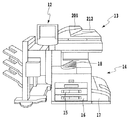
図2は、画像形成装置10の外観を示す図である。
FIG. 2 is a diagram illustrating an appearance of the
画像形成装置10は、上述した通り、操作部12と、スキャナ13と、プリンタ14を備える。
As described above, the
スキャナ13は、原稿搬送部201と光学ユニット212とを備える。光学ユニット212の感度が異なると、たとえ原稿上の各画素の濃度が同じであったとしても、各画素が夫々違う濃度であると認識されてしまう。そのため、スキャナ13は、最初に白板(一様に白い板)を露光走査し、露光走査して得られた反射光の量を電気信号に変換してコントローラ11に出力する。なお、後述するように、コントローラ11内のシェーディング補正部は、スキャナ13から得られた電気信号を元に光学ユニット212の感度の違いを認識する。そして、シェーディング補正部は、この感度の違いを利用して、原稿上の画像をスキャンして得られた電気信号の値を補正する。さらに、シェーディング補正部は、後述するように、コントローラ11内のCPUからゲイン調整の情報を受取ると、当該情報に応じたゲイン調整を行う。ゲイン調整は、原稿を露光走査して得られた電気信号の値を、どのように0〜255の輝度信号値に割り付けるかを調整するために用いられる。このゲイン調整により、原稿を露光走査して得られた電気信号の値を高い輝度信号値に変換したり、低い輝度信号値に変換したりすることができる。
The
続いて、原稿上の画像をスキャンする動作について説明する。 Next, an operation for scanning an image on a document will be described.
原稿は原稿搬送部201のトレイにセットされる。ユーザが操作部12から読み取り開始を指示すると、コントローラは、スキャナ13に対して原稿読み取り指示を送る。スキャナ13は、この指示を受けると原稿搬送部201のトレイから原稿を1枚ずつ分離搬送して、原稿の読み取り動作を行う。
The document is set on the tray of the
スキャナ13は、原稿上の画像を露光走査して得られた反射光を光学ユニットに入力することで画像の情報を電気信号に変換する。さらに、スキャナ13は、電気信号をR、G、Bの各色からなる輝度信号に変換し、当該輝度信号を画像データとしてコントローラ11に対して出力する。
The
プリンタ14は、コントローラ11から受取った画像データを用紙上に形成する画像形成デバイスである。なお、本実施形態における画像形成方式は、感光体ドラムや感光体ベルトを用いた電子写真方式であるが、これに限られることはない。例えば、画像形成方式として、微少ノズルアレイからインクを吐出して用紙上に印字するインクジェット方式等も適用可能である。また、プリンタ14は、異なる用紙サイズ又は異なる用紙向きを選択可能とする複数の用紙カセット15、16、17を備える。排紙トレイ18には、印字後の用紙が排出される。
The
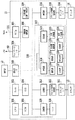
図3は、画像形成装置10のコントローラ11の構成例を示すブロック図である。
FIG. 3 is a block diagram illustrating a configuration example of the
コントローラ11は、スキャナ13やプリンタ14と接続されると共に、LAN50やWAN331を介してPC40や外部装置等と接続される。
The
CPU301は、ROM303に記憶された制御プログラム等に基づいて接続中の各種デバイスを制御すると共に、コントローラ11内部で行われる各種処理についても制御する。RAM302は、CPU301が使用するシステムワークメモリであり、かつ画像データを一時的に記憶するメモリでもある。ROM303は、画像形成装置10のブートプログラム等を格納する。HDD304は、ハードディスクドライブであり、システムソフトウェアや画像データを格納する。
The
操作部I/F305は、システムバス310と操作部12とを接続するためのインタフェースである。操作部I/F305は、操作部12に表示する画像データをシステムバス310から受取り、操作部12に出力すると共に、操作部12から入力された情報をシステムバス310へ出力する。
The operation unit I /
ネットワークI/F306は、LAN50とシステムバス310とを接続する。モデム307は、WAN331とシステムバス310とを接続する。
A network I /
2値画像回転部308は、送信前の画像データの方向を変換する。2値画像圧縮・伸張部309は、送信前の画像データの解像度を所定の解像度や相手能力に合わせた解像度に変換する。なお、圧縮及び伸張にあたってはJBIG、MMR、MR、MHなどの方式が用いられる。
A binary
画像バス330は、コントローラ11内部の各ユニット間で画像データを転送するための伝送路であり、例えば、PCIバス又はIEEE1394である。
The
スキャナ画像処理部312は、スキャナ13からスキャナI/F311を介して受取った画像データに対して、補正、加工、及び編集を行う。また、スキャナ画像処理部312は、受取った画像データの種類を判定する。画像データの種類には、カラー原稿、白黒原稿、文字原稿、写真原稿が含まれる。そして、スキャナ画像処理部312は、判定結果を属性データとして画像データに付随させる。スキャナ画像処理部312で行われる処理の詳細については後述する。
The scanner
圧縮部313は、画像データを32画素×32画素からなるブロック単位に分割する。この32×32画素からなるブロックをタイル画像と呼ぶ。
The
図4は、画像とタイル画像の関係を概念的に示す図である。 FIG. 4 is a diagram conceptually showing the relationship between an image and a tile image.
タイル画像は、32×32画素のタイル画像データを含む。タイル画像データには、32×32画素の平均輝度情報とタイル画像の原稿上の位置がヘッダ情報として付加されている。 The tile image includes tile image data of 32 × 32 pixels. In the tile image data, the average luminance information of 32 × 32 pixels and the position of the tile image on the document are added as header information.
圧縮部313は、複数のタイル画像データからなる画像データを圧縮する。伸張部316は、複数のタイル画像データからなる画像データを伸張した後にラスタ展開してプリンタ画像処理部315に送る。
The
プリンタ画像処理部315は、画像データを受取り、画像データに付随する属性データにしたがって画像データに対して画像処理を施す。プリンタI/F314は、画像処理後の画像データをプリンタ14に出力する。プリンタ画像処理部315で行われる処理の詳細については後述する。
A printer
画像変換部317は、画像データに対して所定の変換処理を施す。画像変換部317は、伸張部318、圧縮部319、回転部320、変換部321、色空間変換部322、2値多値部323、合成部327、移動部325、多値2値部324を備える。
The
伸張部318は、受取った画像データを伸張する。圧縮部319は、受取った画像データを圧縮する。回転部320は、受取った画像データを回転する。変倍部321は、受取った画像データに対し解像度変換処理(例えば600dpiから200dpi)を行う。色空間変換部322は、受取った画像データの色空間を変換する。色空間変換部322は、マトリクス又はテーブルを用いた公知の下地飛ばし処理、公知のLOG変換処理(RGB→CMY)、公知の出力色補正処理(CMY→CMYK)等を行う。2値多値変換部323は、受取った2階調の画像データを256階調の画像データに変換する。多値2値変換部324は、受取った256階調の画像データを誤差拡散処理などの手法を用いて、2階調の画像データに変換する。
The
合成部327は、受取った2つの画像データを合成し1枚の画像データを生成する。2つの画像データを合成する際には、合成対象の画素同士が持つ輝度値の平均値を合成輝度値とする方法や、輝度レベルで明るい方の画素の輝度値を合成後の画素の輝度値とする方法が適用される。また、暗い方を合成後の画素とする方法を利用可能である。さらに合成対象の画素同士の論理和演算、論理積演算、排他的論理和演算などで合成後の輝度値を決定する方法も利用可能である。これらの合成方法はいずれも周知の手法である。
The
間引き部326は、受取った画像データの画素を間引くことで解像度変換を行い、1/2、1/4、1/8などの画像データを生成する。移動部325は、受取った画像データに余白部分をつけ、又は、余白部分を削除する。
The thinning unit 326 performs resolution conversion by thinning out the pixels of the received image data, and generates image data of 1/2, 1/4, 1/8, and the like. The moving
以上が、画像変換部317の内部構成である。
The above is the internal configuration of the
RIP328は、PC40などから送信されたPDLコードデータを元に生成された中間データを受取り、ビットマップデータ(多値)を生成する。
The
図5は、スキャナ画像処理部312の構成例を示すブロック図である。
FIG. 5 is a block diagram illustrating a configuration example of the scanner
スキャナ画像処理部312は、シェーディング補正部500、マスキング処理部501、フィルタ処理部502、ヒストグラム生成部503、入力側ガンマ補正部504、カラーモノクロ判定部505、文字写真判定部506、紙指紋情報取得部507を備える。
The scanner
スキャナ画像処理部312は、RGB各8bitの輝度信号からなる画像データを受取る。
The scanner
シェーディング補正部500は、輝度信号に対してシェーディング補正する。シェーディング補正とは、上述したように、光学ユニットの感度のばらつきによって原稿の明るさが誤認識されてしまうことを防止するための処理である。さらに、上述したように、このシェーディング補正部500は、CPU301からの指示によりゲイン調整を行うことができるようになっている。
The
マスキング処理部501は、シェーディング補正された輝度信号を、光学ユニットのフィルタ色に依存しない標準的な輝度信号に変換する。
The masking
フィルタ処理部502は、受取った画像データの空間周波数を任意に補正する。この処理部は、受取った画像データに対して、例えば7×7のマトリクスを用いた演算処理を行う。ところで、ユーザは、画像形成装置10の操作部12を操作して、コピーモードとして、文字モード、写真モード又は文字/写真モードを選択することができる。ここでユーザにより文字モードが選択された場合には、フィルタ処理部502は、文字用のフィルタを画像データ全体にかける。また、写真モードが選択された場合には、写真用のフィルタを画像データ全体にかける。また、文字/写真モードが選択された場合には、後述の文字写真判定信号(属性データの一部)に応じて画素ごとに適応的にフィルタを切替る。つまり、コピーモードに応じて、画素ごとに写真用のフィルタをかけるか文字用のフィルタをかけるかが決定される。なお、写真用のフィルタには、高周波成分のみ平滑化が行われるような係数が設定されている。これは、画像のざらつきを目立たせないためである。また、文字用のフィルタには、強めのエッジ強調を行うような係数が設定されている。これは、文字のシャープさを出すためである。
The
ヒストグラム生成部503は、受取った画像データを構成する各画素の輝度データをサンプリングする。より詳細に説明すると、ヒストグラム生成部503は、主走査方向、副走査方向にそれぞれ指定した開始点から終了点で囲まれた矩形領域内の輝度データを、主走査方向、副走査方向に一定のピッチでサンプリングする。そして、ヒストグラム生成部503は、サンプリング結果を元にヒストグラムデータを生成する。生成されたヒストグラムデータは、下地飛ばし処理を行う際に下地レベルを推測するために用いられる。
The
入力側ガンマ補正部504は、テーブル等を利用して非線形特性を持つ輝度データに変換する。
The input-side
カラーモノクロ判定部505は、受取った画像データを構成する各画素が有彩色であるか無彩色であるかを判定し、その判定結果をカラーモノクロ判定信号(属性データの一部)として画像データに付随させる。
A color /
文字写真判定部506は、画像データを構成する各画素が文字を構成する画素なのか、網点を構成する画素なのか、網点中の文字を構成する画素なのか、ベタ画像を構成する画素なのかを各画素の画素値と各画素の周辺画素の画素値とに基づいて判定する。なお、どれにもあてはまらない画素は、白領域を構成している画素である。そして、文字写真判定部506は、その判定結果を文字写真判定信号(属性データの一部)として画像データに付随させる。
The character
紙指紋情報取得部507は、シェーディング補正部500から受け取ったRGBの画像データのうち紙指紋情報取得領域として適切な領域を決定し、当該決定された紙指紋情報取得領域の紙指紋情報を取得する。なお、適切な領域ならびに紙指紋情報取得方法については後述する。
The paper fingerprint
図6は、プリンタ画像処理315の構成例を示すブロック図である。
FIG. 6 is a block diagram illustrating a configuration example of the
プリンタ画像処理部315は、下地飛ばし処理部601、モノクロ生成部602、Log変換部603、出力色補正部604、出力側ガンマ補正部605、中間調補正部606を備える。
The printer
下地飛ばし処理部601は、スキャナ画像処理部312で生成されたヒストグラムを用いて画像データの下地色を除去する。
The background
モノクロ生成部602は、カラーデータをモノクロデータに変換する。
The
Log変換部603は、輝度濃度変換を行う。Log変換部603は、例えば、RGB入力された画像データを、CMYの画像データに変換する。
The
出力色補正部604は、出力色補正を行う。例えばCMY入力された画像データを、テーブルやマトリックスを用いてCMYKの画像データに変換する。
The output
出力側ガンマ補正部605は、この出力側ガンマ補正部605に入力される信号値と、複写出力後の反射濃度値とが比例するように補正を行う。
The output-side
中間調補正部606は、出力するプリンタ部の階調数に合わせて中間調処理を行う。例えば、受取った高階調の画像データに対し2値化や32値化などを行う。
A
なお、スキャナ画像処理部312やプリンタ画像処理部315における各処理部では、受取った画像データに各処理を施さずに出力させることも可能となっている。
Each processing unit in the scanner
<紙指紋情報の取得処理及び登録処理>
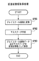
図7は、図5に示す紙指紋情報取得部507が行う紙指紋情報の取得処理を示すフローチャートである。
<Acquisition processing and registration processing of paper fingerprint information>
FIG. 7 is a flowchart showing a paper fingerprint information acquisition process performed by the paper fingerprint
S701では、紙指紋情報取得部507は、画像データをグレイスケールの画像データに変換する。
In step S701, the paper fingerprint
S702では、紙指紋情報取得部507は、グレイスケールの画像データへ変換された画像から紙指紋情報の照合時に誤判定の要因となりうる印刷文字や手書き文字等を取り除くためのマスクデータを作成する。マスクデータは“ 0 ”or“ 1 ”の2値データである。紙指紋情報取得部507は、グレイスケールの画像データにおいて輝度信号値が第1の閾値(つまり、明るい)以上である画素については、マスクデータの値を“ 1 ”に設定する。また、紙指紋情報取得部507は、輝度信号値が第1の閾値未満である画素についてはマスクデータの値を“ 0 ”に設定する。紙指紋情報取得部507は、以上の処理を、グレイスケールの画像データに含まれる各画素に対して行う。
In step S <b> 702, the paper fingerprint
S703では、グレイスケールに変換された画像データと、マスクデータを紙指紋情報として取得する。なお、S701においてグレイスケールに変換された画像データ自体のことを紙指紋情報と称することもあるが、本実施形態では、上記二つのデータを紙指紋情報と呼ぶ。 In S703, the image data converted to gray scale and the mask data are acquired as paper fingerprint information. Note that the image data itself converted to gray scale in S701 may be referred to as paper fingerprint information, but in the present embodiment, the above two data are referred to as paper fingerprint information.
紙指紋情報取得部507は、取得した紙指紋情報を、データバス(図示せず)を介してRAM302に保存する。
The paper fingerprint
また、紙指紋情報の登録処理は、CPU301がRAM302から紙指紋情報を読出し、当該紙指紋情報をサーバ(図示せず)に登録することで実現される。紙指紋情報がサーバに登録された際に、原本を示す管理番号が操作部12に表示される。ユーザは、紙指紋情報照合時にその管理番号を入力することで紙指紋情報の照合を行うことができる。
The paper fingerprint information registration process is realized by the
一方、紙指紋情報の照合処理は、CPU301が、紙指紋情報取得部507がRAM302に保存した原稿の紙指紋情報を読出し、当該読出した紙指紋情報と、既にサーバに登録されている紙指紋情報とを照合することで実現される。なお、本実施形態では管理番号を入力することで紙指紋情報の照合を行っているが、紙指紋情報の登録処理時にユニークなID等を原稿に付加し、そのIDを参照して、照合処理を行ってもよい。
On the other hand, in the paper fingerprint information collation process, the
CPU301は、紙指紋情報取得部507がRAM302に保存した紙指紋情報を読み出し、当該読み出された紙指紋情報(以下、紙指紋情報Aという。)を、既にサーバに登録されている紙指紋情報(以下、紙指紋情報Bという。)と照合する。
The
図8は、紙指紋情報照合処理を示すフローチャートである。本フローチャートの各ステップは、CPU301により制御される。
FIG. 8 is a flowchart showing the paper fingerprint information matching process. Each step of this flowchart is controlled by the
S801において、CPU301は、紙指紋情報Bをサーバから読み出す。
In step S801, the
S802において、CPU301は、紙指紋情報Aと紙指紋情報Bを照合し、マッチング度を算出する。S803において、S802で算出したマッチング度と所定の閾値とを比較して、照合結果(「有効」又は「無効」)を得る。マッチング度とは、紙指紋情報Aと紙指紋情報Bの類似度を示す値である。
In step S802, the
マッチング度を算出するための具体的な方法を図20〜図23を用いて説明する。 A specific method for calculating the degree of matching will be described with reference to FIGS.
図20は、紙指紋情報Aと、紙指紋情報Bを表す図である。各紙指紋情報は、横n画素、縦m画素から構成されているものとする。 FIG. 20 is a diagram showing the paper fingerprint information A and the paper fingerprint information B. Each piece of paper fingerprint information is assumed to be composed of horizontal n pixels and vertical m pixels.

ここで、E(i,j)は、紙指紋情報Aと紙指紋情報Bの誤差値である。α1は、紙指紋情報Bに含まれるマスクデータである。f1は、紙指紋情報Bに含まれるグレイスケール画像データである。α2は、紙指紋情報Aに含まれるマスクデータである。f2は、紙指紋情報Aに含まれるグレイスケール画像データである。 Here, E (i, j) is an error value between the paper fingerprint information A and the paper fingerprint information B. α 1 is mask data included in the paper fingerprint information B. f 1 is grayscale image data included in the paper fingerprint information B. α 2 is mask data included in the paper fingerprint information A. f 2 is grayscale image data included in the paper fingerprint information A.
式(1)において、i,jをそれぞれ−n+1〜n−1、−m+1〜m−1の範囲でそれぞれ1画素毎にずらし、E(i,j)を(2n−1)×(2m−1)個求める。即ち、E(−n+1,−m+1)〜E(n−1,m−1)を求める。
In Expression (1), i and j are shifted by 1 pixel in the range of −
図21(A)は、紙指紋情報Bの左上1画素と、紙指紋情報Aの右下1画素が重なった状態を示す。この状態において、式(1)により求まる誤差値をE(−n+1,−m+1)とする。
FIG. 21A shows a state in which the upper left pixel of the paper fingerprint information B and the lower right pixel of the paper fingerprint information A overlap. In this state, an error value obtained by the equation (1) is assumed to be E (−
図21(B)は、図21(A)に示す状態と比べて、紙指紋情報Aを右に1画素分だけ移動した状態を示す。この状態において、式(1)により求まる誤差値をE(−n+2,−m+1)とする。同様に、紙指紋情報Aを紙指紋情報Bに対して右に1画素ずつ移動させながら誤差値を求める。図21(C)は、紙指紋情報Aの下の画素列と紙指紋情報Bの上の画素列とが重なった状態を示す。この状態において、E(0,−(m−1))を求める。図21(D)は、紙指紋情報Bをさらに右に移動して、紙指紋情報Bの右上1画素と、紙指紋情報Aの左下1画素が重なった状態を示す。この状態において、E(n−1,−m+1)を求める。このように、紙指紋情報Aを紙指紋情報Bに対して右方向に移動するにつれて、E(i,j)の中のiが1ずつ増加する。
FIG. 21B shows a state where the paper fingerprint information A has been moved to the right by one pixel as compared to the state shown in FIG. In this state, the error value obtained from the equation (1) is E (−
図22(A)は、図21(A)に示す状態と比べて、紙指紋情報Aを紙指紋情報Bに対して、縦方向に下に向かって1画素分だけ移動した状態を示す。この状態において、E(−n+1,−m+2)を求める。
FIG. 22A shows a state in which the paper fingerprint information A is moved by one pixel downward in the vertical direction with respect to the paper fingerprint information B, as compared with the state shown in FIG. In this state, E (−
図22(B)は、紙指紋情報Aを紙指紋情報Bの右端まで移動した状態を示す。この状態において、E(n−1,−m+2)を求める。 FIG. 22B shows a state in which the paper fingerprint information A has been moved to the right end of the paper fingerprint information B. In this state, E (n-1, -m + 2) is obtained.
図23(A)は、紙指紋情報Aと紙指紋情報Bが、完全に重なった状態を示す。この状態において、誤差値をE(0,0)とする。 FIG. 23A shows a state in which the paper fingerprint information A and the paper fingerprint information B are completely overlapped. In this state, the error value is E (0, 0).
最後に、図23(B)に示す状態において、E(n−1,m−1)を求める。 Finally, E (n−1, m−1) is obtained in the state shown in FIG.
このように、紙指紋情報Aと紙指紋情報Bとが少なくとも1画素以上重なるように、各紙指紋情報を移動しながら誤差値を求め、その結果、(2n−1)×(2m−1)個の誤差値が得られる。 In this way, an error value is obtained while moving each paper fingerprint information so that the paper fingerprint information A and the paper fingerprint information B overlap at least one pixel, and as a result, (2n-1) × (2m-1) pieces. The error value is obtained.
式(1)の意味内容を考えるために、i=0,j=0であり、かつ、α1(x,y)=1(ただし、x=0〜n,y=0〜m)であり、かつ、α2(x−i,y−j)=1(ただし、x=0〜n,y=0〜m)の場合を例として挙げる。つまり、α1(x,y)=1(ただし、x=0〜n,y=0〜m)であり、かつ、α2(x−i,y−j)=1(ただし、x=0〜n,y=0〜m)の場合のE(0,0)を求めることにする。なお、i=0,j=0の場合とは、図23(A)に示すように、紙指紋情報Aと紙指紋情報Bが完全に重なった状態を示す。 In order to consider the meaning of the expression (1), i = 0, j = 0, and α 1 (x, y) = 1 (where x = 0 to n, y = 0 to m). In addition, a case where α 2 (xi, yj) = 1 (where x = 0 to n, y = 0 to m) is taken as an example. That is, α 1 (x, y) = 1 (where x = 0 to n, y = 0 to m) and α 2 (x−i, y−j) = 1 (where x = 0). E (0,0) in the case of .about.n, y = 0 to m). Note that the case of i = 0 and j = 0 indicates a state in which the paper fingerprint information A and the paper fingerprint information B are completely overlapped as shown in FIG.
α1(x,y)=1(ただし、x=0〜n,y=0〜m)は、紙指紋情報Bの全ての画素が明るいことを示す。言い換えると、紙指紋情報Bが取得された際には、紙指紋取得領域上にはトナーやインクなどの色材やゴミが全くのっていなかったことを示す。 α 1 (x, y) = 1 (where x = 0 to n, y = 0 to m) indicates that all pixels of the paper fingerprint information B are bright. In other words, when the paper fingerprint information B is acquired, it indicates that no color material such as toner or ink or dust is on the paper fingerprint acquisition area.
α2(x−i,y−j)=1(ただし、x=0〜n,y=0〜m)は、紙指紋情報Aの全ての画素が明るいことを示す。言い換えると、紙指紋情報Aが取得された際には、紙指紋取得領域上には一切トナーやインクなどの色材やゴミがのっていなかったことを示す。 α 2 (x−i, y−j) = 1 (where x = 0 to n and y = 0 to m) indicates that all pixels of the paper fingerprint information A are bright. In other words, when the paper fingerprint information A is acquired, it indicates that no color material such as toner or ink or dust is on the paper fingerprint acquisition area.
α1(x,y)=1とα2(x−i,y−j)=1とが全ての画素において成り立つ時、式(1)は、 When α 1 (x, y) = 1 and α 2 (x−i, y−j) = 1 hold in all pixels, the equation (1) becomes
と表される。 It is expressed.
{f1(x,y)−f2(x,y)}2は、紙指紋情報Aの中のグレイスケール画像データと、紙指紋情報Bの中のグレイスケール画像データとの差の二乗値を示す。従って、(1)式は、紙指紋情報Aと紙指紋情報Bの各画素におけるグレイスケール画像データの差の二乗値を合計したものになる。したがって、f1(x,y)とf2(x,y)とが類似するほど、E(0,0)は、小さな値となる。 {F 1 (x, y) −f 2 (x, y)} 2 is the square value of the difference between the gray scale image data in the paper fingerprint information A and the gray scale image data in the paper fingerprint information B Indicates. Therefore, Equation (1) is the sum of the square values of the differences between the gray scale image data in each pixel of the paper fingerprint information A and the paper fingerprint information B. Therefore, E (0, 0) becomes a smaller value as f 1 (x, y) and f 2 (x, y) are more similar.
同様に、他のE(i,j)を求める。f1(x,y)とf2(x,y)とが類似するほどE(i,j)が小さな値となる。したがって、E(k,l)=min{E(i,j)}である場合、紙指紋情報Bを取得した際の紙指紋情報Bの位置と、紙指紋情報Aを取得した際の紙指紋情報Aの位置は、k,lずれていたことになる。 Similarly, other E (i, j) is obtained. The more similar f 1 (x, y) and f 2 (x, y), the smaller E (i, j). Therefore, when E (k, l) = min {E (i, j)}, the position of the paper fingerprint information B when the paper fingerprint information B is acquired and the paper fingerprint when the paper fingerprint information A is acquired. The position of the information A is shifted by k and l.
<αの意義>
式(1)の分子は、{f1(x,y)−f2(x−i,y−j)}2にα1とα2とを掛けた結果を合計した値を示す。α1とα2は、濃い色の画素は0、薄い色の画素は1を示す。従って、α1とα2の少なくとも一方が0の場合には、α1α2{f1(x,y)−f2(x−i,y−j)}2は0になる。つまり、紙指紋情報A又は紙指紋情報Bの少なくとも一方の画素が濃い色である場合には、その画素における濃度差は考慮されない。その理由は、ゴミや色材がのってしまった画素を無視するためである。
<Significance of α>
The numerator of the formula (1) indicates the sum of the results of multiplying {f 1 (x, y) −f 2 (xi, yj)} 2 by α 1 and α 2 . α 1 and α 2 indicate 0 for a dark pixel and 1 for a light pixel. Therefore, when at least one of α 1 and α 2 is 0, α 1 α 2 {f 1 (x, y) −f 2 (xi, y−j)} 2 becomes 0. That is, when at least one pixel of the paper fingerprint information A or the paper fingerprint information B is a dark color, the density difference between the pixels is not considered. The reason for this is to ignore pixels on which dust or color material has been placed.
Σ記号により合計する数が増減するため、Σα1(x,y)α2(x−i,y−j)で割ることで正規化を行う。なお、式(1)の分母にあるΣα1(x,y)α2(x−i,y−j)が0になる誤差値E(i,j)は、後述する誤差値の集合(E(−(n−1),−(m−1))〜E(n−1,m−1))には含まれない。 Since the total number increases or decreases depending on the Σ symbol, normalization is performed by dividing by Σα 1 (x, y) α 2 (x−i, y−j). Note that an error value E (i, j) in which Σα 1 (x, y) α 2 (x−i, y−j) in the denominator of Expression (1) becomes 0 is a set of error values (E (-(N-1),-(m-1)) to E (n-1, m-1)) are not included.
<マッチング度の算出方法>
上述したように、E(k,l)=min{E(i,j)}である場合、紙指紋情報Bを取得した際の紙指紋情報Bの位置と、紙指紋情報Aを取得した際の紙指紋情報Aの位置は、k,lずれている。
<Matching degree calculation method>
As described above, when E (k, l) = min {E (i, j)}, the position of the paper fingerprint information B when the paper fingerprint information B is acquired and the paper fingerprint information A are acquired. The position of the paper fingerprint information A is shifted by k, l.
続いて、紙指紋情報Aと紙指紋情報Bのマッチング度を、E(k,l)とE(i,j)を使って算出する。 Subsequently, the degree of matching between the paper fingerprint information A and the paper fingerprint information B is calculated using E (k, l) and E (i, j).
まず、式(1)により求めた誤差値の集合(例えば、E(0,0)=10,E(0,1)=50,E(1,0)=50,E(1,1)=50)から平均値(40)を求める(A)。次に、平均値(40)から各誤差値(10,50,50,50)を引いて、新たな誤差値の集合(30,−10,−10,−10)を求める(B)。次に、この新たな誤差値の集合から標準偏差(30×30+10×10+10×10+10×10=1200,1200/4=300,√300=10√3=約17)を求める。次に、この新たな誤差値の集合を17で割り、商(1,−1,−1,−1)を求める(C)。次に、求めた商の最大値である1をマッチング度とする。なお、この1は、E(0,0)=10に対応する。ここで、E(0,0)=min{E(i,j)}である。 First, a set of error values obtained by the equation (1) (for example, E (0,0) = 10, E (0,1) = 50, E (1,0) = 50, E (1,1) = The average value (40) is obtained from (50) (A). Next, each error value (10, 50, 50, 50) is subtracted from the average value (40) to obtain a new set of error values (30, −10, −10, −10) (B). Next, a standard deviation (30 × 30 + 10 × 10 + 10 × 10 + 10 × 10 = 1200, 1200/4 = 300, √300 = 10√3 = about 17) is obtained from the set of new error values. Next, this new set of error values is divided by 17 to obtain a quotient (1, -1, -1, -1) (C). Next, 1 which is the maximum value of the obtained quotient is set as the matching degree. This 1 corresponds to E (0,0) = 10. Here, E (0,0) = min {E (i, j)}.
<紙指紋情報照合処理の概念的な説明>
紙指紋情報照合処理は、以下の3つの処理を含む。第1の処理は、複数の誤差値集合の中で最も小さな誤差値が、平均的な誤差値とどれだけずれているかを計算することである。第2の処理は、そのずれの大きさを標準偏差で割ることでマッチング度を求めることである。第3の処理は、マッチング度を閾値と比較することで照合結果を得ることである。標準偏差とは、「各誤差値と平均値との差」の平均的な値を意味する。すなわち、標準偏差は、誤差値集合の中でどれくらい誤差値がばらついているかを示す。このずれの大きさを標準偏差で割ることで、min{E(i,j)}が集合E(i,j)の中で突出して小さいか、又は、ちょっと小さいかがわかる。そして、min{E(i,j)}がE(i,j)の中で突出して小さい場合に「有効」と判断し、それ以外の場合に「無効」と判断する。
<Conceptual explanation of paper fingerprint information matching process>
The paper fingerprint information matching process includes the following three processes. The first process is to calculate how much the smallest error value in the plurality of error value sets deviates from the average error value. The second process is to obtain the matching degree by dividing the magnitude of the deviation by the standard deviation. The third process is to obtain a matching result by comparing the matching degree with a threshold value. The standard deviation means an average value of “difference between each error value and the average value”. That is, the standard deviation indicates how much the error value varies in the error value set. By dividing the magnitude of this deviation by the standard deviation, it can be seen whether min {E (i, j)} protrudes small in the set E (i, j) or is slightly smaller. If min {E (i, j)} is prominently small in E (i, j), it is determined to be “valid”, and otherwise it is determined to be “invalid”.
<min{E(i,j)}が集合E(i,j)の中で突出して小さい場合にのみ有効と判断する理由>
紙指紋情報Aと紙指紋情報Bが同じ紙から取得されたと仮定する。その場合、紙指紋情報Aと紙指紋情報Bとが極めて一致する場所があるはずである。この場所では、E(i,j)は非常に小さな値になる。一方、この位置から少しでもずらすと、紙指紋情報Aと紙指紋情報Bには関連性がなくなるため、E(i,j)は大きな値になる。要するに、「二つの紙指紋情報が同じ紙から取得された」という条件は、「最も小さなE(i,j)が集合E(i,j)の中で突出して小さい」という条件と一致する。
<Reason to determine that min {E (i, j)} is valid only when it is small in the set E (i, j)>
Assume that the paper fingerprint information A and the paper fingerprint information B are obtained from the same paper. In that case, there should be a place where the paper fingerprint information A and the paper fingerprint information B are very consistent. In this place, E (i, j) has a very small value. On the other hand, if the position is slightly shifted from this position, the relationship between the paper fingerprint information A and the paper fingerprint information B is lost, and E (i, j) becomes a large value. In short, the condition that “two pieces of paper fingerprint information have been acquired from the same paper” matches the condition that “the smallest E (i, j) protrudes and is small in the set E (i, j)”.
〈操作部12の構成〉
図9は、画像形成装置の操作部12の構成例を示す図である。
<Configuration of
FIG. 9 is a diagram illustrating a configuration example of the
操作部12は、LCD表示部900、テンキー901、スタートキー902、ストップキー903、リセットキー904、ガイドキー905、コピーモードキー906、ファクスキー907、SENDキー908、スキャナキー909を備える。
The
LCD表示部900は、ユーザインタフェース画面を表示する。
The
画面に表示されるメニュー画面については、図10を用いて後述する。テンキー901は、コピー枚数等の数字を入力する時に使用される。スタートキー902は、ユーザが所望の条件を設定した後、複写動作、原稿の読み取り動作を開始する時などに使用される。ストップキー903は、稼働中の動作を止めるときに使用される。リセットキー904は、操作部からの設定を初期化する時に使用される。ガイドキー905は、キーの機能が解らないとき使用される。コピーモードキー906は、複写を行うときに使用される。ファクスキー907は、ファクスに関する設定を行うときに使用される。SENDキー908は、コンピュータ等の外部装置にファイルデータを出力するときに使用される。スキャナキー909は、コンピュータ等の外部装置から画像読み取りの設定を行うときに使用される。
The menu screen displayed on the screen will be described later with reference to FIG. A
図10は、操作部12のLCD表示部900に表示されるユーザインタフェース画面を示す。
FIG. 10 shows a user interface screen displayed on the
LCD表示部900は、画像形成装置10がコピーできる状態にあるか否かと、ユーザにより設定されたコピー部数を表示する。タブ951は、原稿の種類を選択するために使用され、タブ951を操作することにより、文字モード、写真モード又は文字/写真モードのいずれかを選択できる。タブ952は、シフトソート等のフィニッシングを設定するために使用される。タブ953は、両面読込み及び両面印刷を設定するために使用される。タブ954は、原稿の読み取りモードを選択するために使用される。タブ954を操作することにより、カラー、ブラック又は自動(ACS)のいずれかを選択できる。カラーが選択された場合にはカラーコピーが行われ、ブラックが選択された場合にはモノクロコピーが行われる。ACSが選択された場合には、上述したモノクロカラー判定信号によりコピーモードが決定される。
The
タブ955は、紙指紋情報登録処理を選択するために使用される。紙指紋情報登録処理については、後述する。タブ956は、紙指紋情報照合処理を選択するためのタブである。紙指紋情報照合処理については、後述する。
A
タブ957はシステムの状況を示すためのタブである。タブ957を操作すると、画像形成装置10内のHDD304に保存されている画像データの一覧が画面に表示される。
A
<原稿読み取りモードの設定>
ユーザは、原稿トレイ(原稿載置台)202に原稿を積載し、次いで、操作部12を操作して原稿読み取り方式(原稿固定読み取り方式又は原稿流し読み取り方式)を設定する。また、ユーザは、タブ955またはタブ956を操作して紙指紋情報登録や紙指紋情報照合に関する設定を行う。さらに、ユーザは、原稿のサイズ指定、原稿が両面原稿であるか否か、原稿束が混載原稿であるか否か等も設定する。これらの設定をした後、ユーザは、スタートキー902を押下して原稿の読み取りを起動する。
<Setting the original reading mode>
The user stacks the documents on the document tray (document placement table) 202, and then operates the
〈スキャナの構成例〉
図11は、スキャナ13の構成例を示す図である。
<Example of scanner configuration>
FIG. 11 is a diagram illustrating a configuration example of the
スキャナ13は、原稿搬送部201、原稿トレイ202、分離ユニット203、搬送ローラ204、205、レジストローラ206を備える。さらに、スキャナ13は、読み取りベルト208、排紙ローラ209、排紙トレイ210、裏面光学ユニット211、光学ユニット212、各種センサS1〜S7、VR1を備える。
The
ユーザは、原稿トレイ202上に原稿束をセットする。
The user sets a bundle of documents on the
原稿搬送部201は、原稿トレイ202上にセットされた原稿束を分離ユニット203へ引き込み、原稿束の最上紙を一枚ずつ分離し、搬送ローラ204、205へと搬送する。
The
レジストローラ206は、原稿の先端の到着時には停止している。そして、搬送ローラ204、205による搬送によりループが形成されて斜行補正がされた後に、レジストローラ206は、原稿の搬送を開始する。レジストローラ206と読み取りベルト208は、読み取り位置R1へ所定の速度で原稿を搬送する。原稿の先端が読み取り位置R1に到達すると読み取位置R1に固定された光学ユニット212が露光動作を開始する。原稿の読み取りが終了すると、読み取りベルト208は、原稿を原稿排紙部へ搬送する。
The
原稿排紙部は、排紙ローラ209を用いて原稿を排紙トレイ210へ裏面排出する。また、両面原稿の読み取りが選択された場合には、裏面画像読み取り用の裏面光学ユニット211を用いて原稿の裏面を読み取る。
The document discharge unit discharges the document to the
また、原稿搬送部201内には、原稿トレイ202上で長さを検知するラージサイズ検知センサS1とスモールサイズ検知センサS2、幅検知ボリュームセンサVR1及び幅検知センサS3が設けられている。また、原稿搬送部201内には、原稿の先端及び後端を検知することにより原稿の長さを計測するサイズセンサS4、原稿の先端を検知することにより読み取り開始を知らせるリードセンサS5が設けられている。また、原稿搬送部201内には、排紙センサS6、原稿が原稿トレイ202上にセットされているかどうかを判定する原稿セットセンサS7も設けられている。
Further, a large size detection sensor S1, a small size detection sensor S2, a width detection volume sensor VR1, and a width detection sensor S3 that detect the length on the
図12は、原稿搬送部201の制御系のハードウェアの構成を示すブロック図である。
FIG. 12 is a block diagram illustrating a hardware configuration of a control system of the
原稿搬送部201は、CPU251、ROM252、RAM253、CPUインタフェース254を備える。CPU251は、CPUインタフェース254を介して、コントローラ11のCPU301と通信を行う。特に、CPU251は、CPU301から命令を受けて、原稿搬送部201全体の制御を行うと共に各種センサから受け取ったデータを処理する。ROM252は、制御プログラムを格納する。RAM253は、制御データを一時的に記憶する。
The
<原稿束の分離処理>
図13は、スタートキー902が押下された後の原稿束の分離処理を示すフローチャートである。この分離処理は、原稿搬送制御部201のCPU251により制御される。
<Document separation processing>
FIG. 13 is a flowchart showing the separation processing of the original bundle after the
A4サイズの2枚の原稿が原稿トレイ202にセットされているとする。
Assume that two A4 size originals are set on the
スタートキー902が押されると、CPU251は、ユーザにより原稿サイズが設定されているかどうかを判定する(S1301)。
When the
ユーザにより原稿サイズが設定されていない場合には、CPU251は、各種センサが検知した信号に基づいて、原稿サイズを判定する(S1302)。各種センサとは、原稿トレイ105上に配置されたスモールサイズ検知センサS1、ラージサイズ検知センサS2、幅検知ボリュームVR1、幅検知センサS3のことである。本実施形態では、原稿サイズはA4サイズとする。
If the document size is not set by the user, the
原稿搬送部201は、原稿トレイ202上にセットされた原稿束を分離ユニット203へ引き込み、分離ユニット203は、原稿束の1枚目(N=1)を分離し搬送ローラ204、205へと搬送する(S1303)。
The
1枚目の原稿の後端がサイズセンサS4を通過すると、サイズセンサS4は、OFF信号を出力する。CPU251は、サイズセンサS4からOFF信号を受けると、原稿の長さを判定する(S1304)。これは、原稿混載が設定された際に各原稿の長さを判定するために行われる。
When the trailing edge of the first document passes through the size sensor S4, the size sensor S4 outputs an OFF signal. Upon receiving the OFF signal from the size sensor S4, the
CPU251は、次の原稿があるかどうかを原稿セットセンサS7の出力信号に基づいて判定する(S1305)。CPU251は、原稿セットセンサS7がON信号を出力している場合には次の原稿が原稿トレイ105上にあると判断し、N=N+1とする(S1307)。続いて、CPU251は、原稿束の2枚目(N=2)を分離する(S1306)。CPU251は、最終原稿が分離されるまで上記処理を繰り返す。CPU251は、原稿セットセンサS9がOFF信号を出力したときには、最終原稿の分離が終了したと判断し、分離処理を終了する。
The
<原稿固定読み取りモードでの紙指紋情報読み取り/登録処理>
図14は、原稿固定読み取りモードで紙指紋情報を読み取り、当該紙指紋情報を登録する処理の流れを示すフローチャートである。本処理では、原稿束の全ての原稿の紙指紋情報登録を行う。図15は、当該処理を行うスキャナの構成例を示す図である。
<Paper fingerprint information reading / registration process in original fixed reading mode>
FIG. 14 is a flowchart showing a flow of processing for reading paper fingerprint information in the original fixed reading mode and registering the paper fingerprint information. In this process, paper fingerprint information registration of all the originals in the original bundle is performed. FIG. 15 is a diagram illustrating a configuration example of a scanner that performs the processing.
1枚目の原稿(N=1)の先端がレジストローラ206で斜行補正をした後、CPU251は、1枚目の原稿の後端がリードセンサS5に到達するまで待つ。すなわち、CPU251は、リードセンサS5がOFF信号を出力したかどうかを判定する(S1401)。
After correcting the skew of the leading edge of the first document (N = 1) by the
CPU251は、1枚目の原稿を光学ユニット212の位置Rm(m=1)で原稿台ガラス上に停止させる(S1402)。光学ユニットは、移動式の画像読み取り手段である。
The
CPU251は、位置R1上で、光学ユニット212を走査させて、1回目の紙指紋情報の読み取りを開始する(S1403)。
The
CPU251は、紙指紋情報の1回目の読み取りが終了すると、原稿搬送を再開し、原稿を位置Rm(m=2)まで移動させて停止させる(S1404)。
When the first reading of the paper fingerprint information is completed, the
CPU251は、原稿が位置R2で停止すると、光学ユニット212を走査させて、S1403で紙指紋情報を読み取った紙領域と同じ紙領域の紙指紋情報の読み取りを開始する(S1405)。すなわち、CPU251は、紙指紋情報の2回目の読み取りを開始する。
When the original stops at the position R2, the
CPU251は、1回目で読み取った紙指紋情報と2回目で読み取った紙指紋情報とを比較する(S1406)。
The
CPU251は、両者が一致すれば、その紙指紋情報をサーバに登録する(S1407)。
If the two match, the
CPU251は、両者が異なれば、原稿搬送を再開し、原稿を位置Rm(m=3)まで移動させて停止させる。CPU251は、原稿を位置Rm(m=3)で停止させると、光学ユニット212を走査させて、紙指紋情報の3回目の読み取りを開始する。CPU251は、比較する紙指紋情報が一致するまで、S1404からS1406までの処理を所定回数繰り返す。
If they are different, the
CPU251は、1枚目の紙指紋情報を登録すると、2枚目の原稿があるかどうかを判定し(S1408)、2枚目の原稿がある場合には、N=N+1とすると共に光学ユニット212を位置R1に戻す(S1409)。
When the first paper fingerprint information is registered, the
CPU251は、再びS1401〜S1407の処理を行い、2枚目の原稿の紙指紋情報を読み取り、登録を行う。
The
CPU251は、全ての原稿の紙指紋情報の読み取り、登録が完了するまでS1407〜S1409の処理を行う。
The
<流し読みとりモードでの紙指紋情報読み取り/登録処理>
図16は、原稿流し読み取りモードで紙指紋情報を読み取り、当該紙指紋情報を登録する処理の流れを示すフローチャートである。図15は、当該処理を行うスキャナの構成例を示す図である。
<Paper fingerprint information reading / registration process in sink reading mode>
FIG. 16 is a flowchart showing the flow of processing for reading paper fingerprint information in the original flow reading mode and registering the paper fingerprint information. FIG. 15 is a diagram illustrating a configuration example of a scanner that performs the processing.
1枚目の原稿(N=1)の先端がレジストローラ206で斜行補正をした後に、CPU251は、1枚目の原稿の先端がリードセンサS5に到達するまで待つ。すなわち、CPU251は、リードセンサS5がON信号を出力したかどうかを判定する(S1601)。
After correcting the skew of the leading edge of the first document (N = 1) by the
CPU251は、光学ユニット212を位置Rm(m=1)で固定し、1枚目の原稿を搬送させながら紙指紋情報の読み取りを開始する(S1602)。
The
CPU251は、紙指紋情報の1回目の読み取りが終了すると、原稿を位置Rm(m=1)に停止させる(S1603)。
When the first reading of the paper fingerprint information is completed, the
CPU251は、光学ユニット212を位置Rm(m=2)まで移動して停止させる(S1604)。
The
CPU251は、光学ユニット212が位置Rm(m=2)で停止すると、原稿を搬送させながら、S1602で紙指紋情報を読み取った紙領域と同じ紙領域の紙指紋情報の読み取りを開始する(S1605)。すなわち、CPU251は、紙指紋情報の2回目の読み取りを開始する。
When the
CPU251は、1回目で読み取った紙指紋情報と2回目で読み取った紙指紋情報とを比較する(S1606)。
The
CPU251は、両者が一致すれば、その紙指紋情報をサーバに登録する(S1607)。
If the two match, the
CPU251は、両者が異なれば、再度、光学ユニット212を移動させ、Rm(m=3)で停止させる。CPU251は、光学ユニット212を位置Rm(m=3)で停止させると、原稿を搬送させて、紙指紋情報の3回目の読み取りを開始する。CPU251は、比較する紙指紋情報が一致するまで、S1604からS1606までの処理を所定回数繰り返す。
If they are different, the
CPU251は、1枚目の紙指紋情報を登録すると、2枚目の原稿があるかどうかを判定し(S1608)、2枚目の原稿がある場合には、N=N+1とすると共に光学ユニット212を位置Rm(m=1)に戻す(S1609)。
When the first paper fingerprint information is registered, the
CPU251は、S1601〜S1607の処理を行い、2枚目の原稿の紙指紋情報を読み取り、登録を行う。
The
CPU251は、全ての原稿の紙指紋情報の読み取り、登録が完了するまでS1607〜S1609の処理を行う。
The
<原稿固定読み取りモードでの紙指紋情報読み取り/照合処理>
図17は、原稿固定読み取りモードで紙指紋情報を照合する処理の流れを示すフローチャートである。本処理では、原稿束の全ての原稿の紙指紋情報の照合を行う。
<Paper fingerprint information reading / collation processing in original fixed reading mode>
FIG. 17 is a flowchart showing a flow of processing for collating paper fingerprint information in the original fixed reading mode. In this processing, paper fingerprint information of all the originals in the original bundle is collated.
1枚目の原稿(N=1)の先端がレジストローラ206で斜行補正をした後に、CPU251は、1枚目の原稿の後端がリードセンサS5に到達するまで待つ。すなわち、CPU251は、リードセンサS5がOFF信号を出力したかどうかを判定する(S1701)。
After correcting the skew of the leading edge of the first document (N = 1) by the
CPU251は、1枚目の原稿を光学ユニット212の位置Rm(m=1)で原稿台ガラス上に停止させる(S1702)。
The
CPU251は、位置R1上で、光学ユニット212を走査させて、1回目の紙指紋情報の読み取りを開始する(S1703)。
The
CPU251は、紙指紋情報の1回目の読み取りが終了すると、原稿搬送を再開し、原稿を位置Rm(m=2)まで移動させて停止させる(S1704)。
When the first reading of the paper fingerprint information is completed, the
CPU251は、原稿が位置R2で停止すると、光学ユニット212を走査させて、S1703で紙指紋情報を読み取った紙領域と同じ紙領域の紙指紋情報の読み取りを開始する(S1705)。すなわち、CPU251は、紙指紋情報の2回目の読み取りを開始する。
When the original stops at the position R2, the
CPU251は、1回目で読み取った紙指紋情報と2回目で読み取った紙指紋情報とを比較する(S1706)。
The
CPU251は、両者が一致することを検出すれば、その紙指紋情報をRAM253に格納し、S1707の処理に進む。CPU251は、両者が異なれば、原稿搬送を再開し、原稿を位置Rm(m=3)まで移動させて停止させる。CPU251は、原稿を位置Rm(m=3)で停止させると、光学ユニット212を走査させて、紙指紋情報の3回目の読み取りを開始する。CPU251は、比較する紙指紋情報が一致するのを検出するまで、S1704からS1706までの処理を所定回数繰り返す。
If the
CPU301は、サーバに登録されている紙指紋情報と、RAM253に格納されている紙指紋情報とを照合する(S1707)。
The
S1707で照合した結果、両者が一致するのを検出すれば、CPU251は、2枚目の原稿があるかどうかを判定し(S1708)、2枚目の原稿がある場合には、N=N+1とすると共に光学ユニット212を位置R1に戻す(S1709)。
If it is detected as a result of the collation in S1707 that the two match, the
CPU251、CPU301は、再びS1701〜S1707の処理を行い、2枚目の原稿の紙指紋情報の照合を行う。
The
CPU251、CPU301は、全ての原稿の紙指紋情報の照合が完了するまでS1707〜S1709の処理を行う。
The
S1707で紙指紋情報を照合した結果、両者の不一致を検出した場合、読み取った原稿を排紙すると共に操作部12上に照合が失敗した旨(例えば、原稿が原本とは異なることを示すメッセージ)を表示し、処理を終了する(S1710)。 As a result of collating the paper fingerprint information in S1707, if a mismatch between the two is detected, the read original is discharged and the collation failed on the operation unit 12 (for example, a message indicating that the original is different from the original) Is displayed, and the process ends (S1710).
図19は、位置R1、R2、R3で読み取られた紙指紋情報K1、K2、K3を示す図である。 FIG. 19 is a diagram showing the paper fingerprint information K1, K2, and K3 read at the positions R1, R2, and R3.
本図においては、位置R1で読み取られた紙指紋情報K1が位置R2で読み取られた紙指紋情報K2とは一致しないが、位置R3で読み取られた紙指紋情報K3と一致している場合を示す。紙指紋情報の照合は、公知の照合方法を用いればよい。 This figure shows a case where the paper fingerprint information K1 read at position R1 does not match the paper fingerprint information K2 read at position R2, but matches the paper fingerprint information K3 read at position R3. . A known collation method may be used for collation of the paper fingerprint information.
<原稿流し読み取りモードでの紙指紋情報読み取り/照合処理>
図18は、原稿流し読み取りモードで紙指紋情報を照合する処理の流れを示すフローチャートである。本処理では、原稿束の全ての原稿の紙指紋情報の照合を行う。
<Paper fingerprint information reading / collation processing in document-scanning reading mode>
FIG. 18 is a flowchart showing a flow of processing for collating paper fingerprint information in the document flow reading mode. In this processing, paper fingerprint information of all the originals in the original bundle is collated.
1枚目の原稿(N=1)の先端がレジストローラ206で斜行補正をした後に、CPU251は、1枚目の原稿の先端がリードセンサS5に到達するまで待つ(S1801)。すなわち、CPU251は、リードセンサS5がON信号を出力したかどうかを判定する(S1801)。
After correcting the skew of the leading edge of the first document (N = 1) by the
CPU251は、光学ユニット212を位置Rm(m=1)で固定し、1枚目の原稿を搬送させながら紙指紋情報の読み取りを開始する(S1802)。
The
CPU251は、紙指紋情報の1回目の読み取りが終了すると、原稿を位置Rm(m=1)に停止させる(S1803)。
When the first reading of the paper fingerprint information is completed, the
CPU251は、光学ユニット212を位置Rm(m=2)まで移動して停止させる(S1804)。
The
CPU251は、光学ユニット212が位置Rm(m=2)で停止すると、原稿を搬送させながら、S1802で紙指紋情報を読み取った紙領域と同じ紙領域の紙指紋情報の読み取りを開始する(S1805)。すなわち、CPU251は、紙指紋情報の2回目の読み取りを開始する。
When the
CPU251は、1回目で読み取った紙指紋情報と2回目で読み取った紙指紋情報とを比較する(S1806)。
The
CPU251は、両者が一致するのを検出すれば、その紙指紋情報をRAM253に格納し、S1807の処理に進む。CPU251は、両者が異なれば、再度、光学ユニット212を移動させ、Rm(m=3)で停止させる。CPU251は、光学ユニット212を位置Rm(m=3)で停止させると、原稿を搬送させて、紙指紋情報の3回目の読み取りを開始する。
If the
CPU251は、比較する紙指紋情報が一致するのを検出するまで、S1804からS1806までの処理を所定回数繰り返す。
The
CPU301は、サーバに登録されている紙指紋情報と、RAM253に格納されている紙指紋情報とを照合する(S1807)。
The
S1807で照合した結果、両者が一致すれば、CPU251は、2枚目の原稿があるかどうかを判定し(S1808)、2枚目の原稿がある場合には、N=N+1とすると共に光学ユニット212を位置R1に戻す(S1809)。
If they match as a result of the collation in S1807, the
CPU251、CPU301は、再びS1801〜S1807の処理を行い、2枚目の原稿の紙指紋情報の照合を行う。
The
CPU251、CPU301は、全ての原稿の紙指紋情報の照合が完了するまでS1807〜S1809の処理を行う。
The
S1807で紙指紋情報を照合した結果、両者の不一致を検出した場合、読み取った原稿を排紙すると共に操作部12上に照合が失敗した旨(例えば、原稿が原本とは異なることを示すメッセージ)を表示し、処理を終了する(S1810)。
(その他の実施形態)
本発明は、前述の実施例の機能を実現するソフトウェアのプログラムコードを記録した記録媒体をシステムあるいは装置に装着し、システム等のコンピュータが記録媒体からプログラムコードを読み取り実行することによっても達成される。記録媒体はコンピュータ読み取り可能な記録媒体である。この場合、記録媒体から読み出されたプログラムコード自体が前述した実施例の機能を実現することになり、そのプログラムコードを記憶した記録媒体は本発明を構成する。また、プログラムコードの指示に基づき、コンピュータ上で稼働しているオペレーティングシステム(OS)などが実際の処理の一部または全部を行い、その処理によって前述した実施例の機能が実現されてもよい。また、記録媒体から読み出されたプログラムコードが、コンピュータの機能拡張カードや機能拡張ユニットに書込まれた後、機能拡張カード等がプログラムコードの指示に基づき処理の一部または全部を行うことで、前述の実施例を実現してもよい。
As a result of collating the paper fingerprint information in S1807, if a mismatch between the two is detected, the read original is discharged and the collation failed on the operation unit 12 (for example, a message indicating that the original is different from the original) Is displayed, and the process ends (S1810).
(Other embodiments)
The present invention can also be achieved by mounting a recording medium on which a program code of software for realizing the functions of the above-described embodiments is recorded in a system or apparatus, and a computer such as the system reads and executes the program code from the recording medium. . The recording medium is a computer-readable recording medium. In this case, the program code read from the recording medium itself realizes the functions of the above-described embodiments, and the recording medium storing the program code constitutes the present invention. Further, based on the instruction of the program code, an operating system (OS) running on the computer may perform part or all of the actual processing, and the functions of the above-described embodiments may be realized by the processing. In addition, after the program code read from the recording medium is written to the function expansion card or function expansion unit of the computer, the function expansion card or the like performs part or all of the processing based on the instruction of the program code. The embodiments described above may be implemented.
本発明を上記記録媒体に適用する場合、その記録媒体には、先に説明したフローチャートに対応するプログラムコードが格納される。 When the present invention is applied to the recording medium, the recording medium stores program codes corresponding to the flowcharts described above.
11 コントローラ
12 操作部
13 スキャナ
201 原稿搬送部
202 原稿トレイ
203 分離ユニット
204、205 搬送ローラ
206 レジストローラ
208 読み取りベルト
209 排紙ローラ
210 排紙トレイ
212 光学ユニット
251 CPU
301 CPU
312 スキャナ画像処理部
507 紙指紋情報取得部
11
301 CPU
312 Scanner
Claims (14)
前記原稿の紙指紋情報を読み取る読み取り手段と、
前記原稿を第1の位置に固定し、前記読み取り手段によって読み取った第1の紙指紋情報と、前記原稿を第2の位置に固定し、前記読み取り手段によって読み取った第2の紙指紋情報とを比較する第1の比較手段と、
前記第1の比較手段が前記第1の紙指紋情報と前記第2の紙指紋情報が一致することを検出した場合、当該紙指紋情報を取得する手段
を備えることを特徴とする画像読み取り装置。 Transport means for transporting a document loaded on the document table to a plurality of positions;
Reading means for reading paper fingerprint information of the original;
The first paper fingerprint information read by the reading unit with the original fixed at the first position and the second paper fingerprint information read by the reading unit with the original fixed at the second position. First comparing means for comparing;
An image reading apparatus comprising: means for acquiring the paper fingerprint information when the first comparing means detects that the first paper fingerprint information and the second paper fingerprint information match.
前記原稿の紙指紋情報を読み取る移動式の読み取り手段と、
前記読み取り手段を第1の位置に固定し、前記原稿を移動させることによって読み取った第1の紙指紋情報と、前記読み取り手段を第2の位置に固定し、前記原稿を移動させることによって読み取った第2の紙指紋情報とを比較する第1の比較手段と、
前記第1の比較手段が前記第1の紙指紋情報と前記第2の紙指紋情報が一致することを検出した場合、当該紙指紋情報を取得する手段
を備えることを特徴とする画像読み取り装置。 Transport means for transporting a document loaded on the document table to a plurality of positions;
Mobile reading means for reading the paper fingerprint information of the document;
The first paper fingerprint information read by fixing the reading means at the first position and moving the document, and the reading by fixing the reading means at the second position and moving the document First comparison means for comparing with the second paper fingerprint information;
An image reading apparatus comprising: means for acquiring the paper fingerprint information when the first comparing means detects that the first paper fingerprint information and the second paper fingerprint information match.
前記原稿の紙指紋情報を読み取る移動式の読み取り手段と、
前記原稿を第1の位置に固定し、前記読み取り手段を移動させることによって読み取った第1の紙指紋情報と、前記原稿を第2の位置に固定し、前記読み取り手段を移動させることによって読み取った第2の紙指紋情報とを比較する第1の比較手段と、
前記読み取り手段を第3の位置に固定し、前記原稿を移動させることによって読み取った第3の紙指紋情報と、前記読み取り手段を第4の位置に固定し、前記原稿を移動させることによって読み取った第4の紙指紋情報とを比較する第2の比較手段と、
前記第1の比較手段が前記第1の紙指紋情報と前記第2の紙指紋情報が一致することを検出した場合、又は、前記第2の比較手段が前記3の紙指紋情報と前記第4の紙指紋情報が一致することを検出した場合に、一致した紙指紋情報を取得する手段
を備えることを特徴とする画像読み取り装置。 Transport means for transporting a document loaded on the document table to a plurality of positions;
Mobile reading means for reading the paper fingerprint information of the document;
The first paper fingerprint information read by moving the reading means while the original is fixed at the first position, and read by moving the reading means while fixing the original at the second position. First comparison means for comparing with the second paper fingerprint information;
The third paper fingerprint information read by fixing the reading means at the third position and moving the document, and the reading by fixing the reading means at the fourth position and moving the document A second comparison means for comparing the fourth paper fingerprint information;
When the first comparison unit detects that the first paper fingerprint information and the second paper fingerprint information match, or the second comparison unit detects the third paper fingerprint information and the fourth paper fingerprint information. An image reading apparatus comprising: means for acquiring matched paper fingerprint information when it is detected that the paper fingerprint information matches.
読み取り手段が前記原稿の紙指紋情報を読み取るステップと、
前記原稿を第1の位置に固定し、前記読み取り手段によって読み取った第1の紙指紋情報と、前記原稿を第2の位置に固定し、前記読み取り手段によって読み取った第2の紙指紋情報とを比較するステップと、
前記比較した結果、前記第1の紙指紋情報と前記第2の紙指紋情報が一致することを検出した場合、当該紙指紋情報を取得するステップ
を含むことを特徴とする画像読み取り方法。 Transporting a document loaded on a document table to a plurality of positions;
Reading means for reading the paper fingerprint information of the document;
The first paper fingerprint information read by the reading unit with the original fixed at the first position and the second paper fingerprint information read by the reading unit with the original fixed at the second position. A step of comparing;
As a result of the comparison, when it is detected that the first paper fingerprint information matches the second paper fingerprint information, the image reading method includes: acquiring the paper fingerprint information.
移動式の読み取り手段が前記原稿の紙指紋情報を読み取るステップと、
前記読み取り手段を第1の位置に固定し、前記原稿を移動させることによって読み取った第1の紙指紋情報と、前記読み取り手段を第2の位置に固定し、前記原稿を移動させることによって読み取った第2の紙指紋情報とを比較するステップと、
前記第比較した結果、前記第1の紙指紋情報と前記第2の紙指紋情報が一致することを検出した場合、当該紙指紋情報を取得するステップ
を含むことを特徴とする画像読み取り方法。 Transporting a document loaded on a document table to a plurality of positions;
A mobile reading means reading the paper fingerprint information of the document;
The first paper fingerprint information read by fixing the reading means at the first position and moving the document, and the reading by fixing the reading means at the second position and moving the document Comparing the second paper fingerprint information;
An image reading method comprising: acquiring the paper fingerprint information when it is detected as a result of the first comparison that the first paper fingerprint information matches the second paper fingerprint information.
移動式の読み取り手段が前記原稿の紙指紋情報を読み取るステップと、
前記原稿を第1の位置に固定し、前記読み取り手段を移動させることによって読み取った第1の紙指紋情報と、前記原稿を第2の位置に固定し、前記読み取り手段を移動させることによって読み取った第2の紙指紋情報とを比較するステップと、
前記読み取り手段を第3の位置に固定し、前記原稿を移動させることによって読み取った第3の紙指紋情報と、前記読み取り手段を第4の位置に固定し、前記原稿を移動させることによって読み取った第4の紙指紋情報とを比較するステップと、
前記第1の紙指紋情報と前記第2の紙指紋情報が一致することを検出した場合、又は、前記第3の紙指紋情報と前記第4の紙指紋情報が一致することを検出した場合、一致した紙指紋情報を取得するステップ
を含むことを特徴とする画像読み取り方法。 Transporting a document loaded on a document table to a plurality of positions;
A mobile reading means reading the paper fingerprint information of the document;
The first paper fingerprint information read by moving the reading means while the original is fixed at the first position, and read by moving the reading means while fixing the original at the second position. Comparing the second paper fingerprint information;
The third paper fingerprint information read by fixing the reading means at the third position and moving the document, and the reading by fixing the reading means at the fourth position and moving the document Comparing the fourth paper fingerprint information;
When it is detected that the first paper fingerprint information and the second paper fingerprint information match, or when the third paper fingerprint information and the fourth paper fingerprint information match, An image reading method comprising: obtaining matched paper fingerprint information.
Priority Applications (2)
| Application Number | Priority Date | Filing Date | Title |
|---|---|---|---|
| JP2007242668A JP2009077049A (en) | 2007-09-19 | 2007-09-19 | Image reader |
| US12/211,394 US8054516B2 (en) | 2007-09-19 | 2008-09-16 | Device for scanning and verifying a plurality of paper fingerprints |
Applications Claiming Priority (1)
| Application Number | Priority Date | Filing Date | Title |
|---|---|---|---|
| JP2007242668A JP2009077049A (en) | 2007-09-19 | 2007-09-19 | Image reader |
Publications (2)
| Publication Number | Publication Date |
|---|---|
| JP2009077049A true JP2009077049A (en) | 2009-04-09 |
| JP2009077049A5 JP2009077049A5 (en) | 2010-11-04 |
Family
ID=40454146
Family Applications (1)
| Application Number | Title | Priority Date | Filing Date |
|---|---|---|---|
| JP2007242668A Withdrawn JP2009077049A (en) | 2007-09-19 | 2007-09-19 | Image reader |
Country Status (2)
| Country | Link |
|---|---|
| US (1) | US8054516B2 (en) |
| JP (1) | JP2009077049A (en) |
Cited By (1)
| Publication number | Priority date | Publication date | Assignee | Title |
|---|---|---|---|---|
| US8792723B2 (en) | 2010-09-03 | 2014-07-29 | Fuji Xerox Co., Ltd. | Image processing apparatus and computer readable medium |
Families Citing this family (8)
| Publication number | Priority date | Publication date | Assignee | Title |
|---|---|---|---|---|
| JP2011079672A (en) * | 2009-09-11 | 2011-04-21 | Ricoh Co Ltd | Document feed device, image forming device, and method of feeding document |
| US20110080603A1 (en) * | 2009-10-02 | 2011-04-07 | Horn Richard T | Document Security System and Method for Authenticating a Document |
| JP5754096B2 (en) * | 2010-08-05 | 2015-07-22 | 富士ゼロックス株式会社 | Image processing apparatus, image processing system, and program |
| JP6044059B2 (en) * | 2011-09-16 | 2016-12-14 | 富士ゼロックス株式会社 | Object information management system and program. |
| US8805865B2 (en) * | 2012-10-15 | 2014-08-12 | Juked, Inc. | Efficient matching of data |
| US9836637B2 (en) * | 2014-01-15 | 2017-12-05 | Google Llc | Finger print state integration with non-application processor functions for power savings in an electronic device |
| US9325672B2 (en) * | 2014-04-25 | 2016-04-26 | Cellco Partnership | Digital encryption shredder and document cube rebuilder |
| US11281787B2 (en) | 2018-06-05 | 2022-03-22 | Hewlett-Packard Development Company, L.P. | Electronic device with sensor to detect first and second codes and to further performs first and second digital scan of print medium |
Family Cites Families (15)
| Publication number | Priority date | Publication date | Assignee | Title |
|---|---|---|---|---|
| US4491960A (en) * | 1982-04-05 | 1985-01-01 | The United States Of America As Represented By The Secretary Of The Navy | Handprinted symbol recognition system |
| US4958235A (en) * | 1989-01-05 | 1990-09-18 | Appalachian Computer Services | System and method for rapidly conveying document images between distant locations |
| US5280330A (en) * | 1990-07-12 | 1994-01-18 | Nisca Corporation | Automatic document feeding device |
| US5119213A (en) * | 1990-07-27 | 1992-06-02 | Xerox Corporation | Scanner document absence code system |
| JP3359122B2 (en) | 1993-10-13 | 2002-12-24 | キヤノン株式会社 | Copying system |
| US6910687B1 (en) * | 1999-07-13 | 2005-06-28 | Arrowhead Systems Llc | Separator sheet handling assembly |
| US6574631B1 (en) * | 2000-08-09 | 2003-06-03 | Oracle International Corporation | Methods and systems for runtime optimization and customization of database applications and application entities |
| US7190470B2 (en) * | 2001-04-05 | 2007-03-13 | Hewlett-Packard Development Company, L.P. | System and method for automatic document verification |
| AU2002318165A1 (en) * | 2001-05-25 | 2002-12-09 | Biometric Informatics Technology, Inc. | Fingerprint recognition system |
| JP4103826B2 (en) | 2003-06-24 | 2008-06-18 | 富士ゼロックス株式会社 | Authenticity determination method, apparatus and program |
| US6942308B2 (en) * | 2003-10-10 | 2005-09-13 | Hewlett-Packard Development Company, L.P. | Compensation of lateral position changes in printing |
| JP2006012136A (en) * | 2004-06-03 | 2006-01-12 | Oce Technologies Bv | Control of document processing based on fingerprint of user |
| US7809156B2 (en) * | 2005-08-12 | 2010-10-05 | Ricoh Company, Ltd. | Techniques for generating and using a fingerprint for an article |
| US7627161B2 (en) * | 2005-11-28 | 2009-12-01 | Fuji Xerox Co., Ltd. | Authenticity determination method, apparatus and program |
| US7865124B2 (en) * | 2007-03-30 | 2011-01-04 | Ricoh Company, Ltd. | Pre-scanning printer with paper fingerprinting |
-
2007
- 2007-09-19 JP JP2007242668A patent/JP2009077049A/en not_active Withdrawn
-
2008
- 2008-09-16 US US12/211,394 patent/US8054516B2/en not_active Expired - Fee Related
Cited By (1)
| Publication number | Priority date | Publication date | Assignee | Title |
|---|---|---|---|---|
| US8792723B2 (en) | 2010-09-03 | 2014-07-29 | Fuji Xerox Co., Ltd. | Image processing apparatus and computer readable medium |
Also Published As
| Publication number | Publication date |
|---|---|
| US20090073517A1 (en) | 2009-03-19 |
| US8054516B2 (en) | 2011-11-08 |
Similar Documents
| Publication | Publication Date | Title |
|---|---|---|
| JP4732315B2 (en) | Image processing apparatus and method | |
| JP4810413B2 (en) | Image processing apparatus and image processing method | |
| JP4836260B2 (en) | Image forming apparatus, image forming method, recording medium, and program | |
| JP4886584B2 (en) | Image processing apparatus, image processing method, and program thereof | |
| JP2009077049A (en) | Image reader | |
| JP4834531B2 (en) | Image processing apparatus, image processing apparatus control method, and program | |
| JP2008271418A (en) | Image forming unit | |
| JP4732314B2 (en) | Image processing apparatus and image processing method | |
| JP4812106B2 (en) | Image reading apparatus and control method thereof | |
| JP2009075751A (en) | Image processing apparatus, image processing method, program of same, and computer-readable storage medium | |
| JP4663682B2 (en) | Image processing apparatus, image processing method, program, and storage medium | |
| JP2009005091A (en) | Image forming apparatus, control method of the same, program and storage medium | |
| JP2008283586A (en) | Image processor, control method of image processor, program and storage medium | |
| JP4709090B2 (en) | Image processing apparatus, image processing apparatus control method, and program | |
| JP2008141683A (en) | Image processor, method and program, and storage medium | |
| US8184341B2 (en) | Image reading apparatus, image reading method, and storage medium | |
| JP4267029B2 (en) | Image processing apparatus, image processing method, image processing method program, and storage medium therefor | |
| US8059296B2 (en) | Image forming apparatus that synthesizes fiber information extracted from pages of a paper medium having a plurality of pages, and an image forming apparatus control method, a program, and a storage medium relating thereto | |
| JP2009200746A (en) | Image forming apparatus and image forming method | |
| JP2010050551A (en) | Image formation device | |
| JP4886639B2 (en) | Image reading apparatus and image reading method | |
| JP2008293267A (en) | Image forming apparatus equipped with original conveyance device and original reading device and method for controlling image processor | |
| JP2008066840A (en) | Image processor, image processing method, program of image processing method and its storage medium | |
| JP2010056912A (en) | Image processing apparatus | |
| JP2009071355A (en) | Image reading apparatus and image reading method |
Legal Events
| Date | Code | Title | Description |
|---|---|---|---|
| A521 | Request for written amendment filed |
Free format text: JAPANESE INTERMEDIATE CODE: A523 Effective date: 20100921 |
|
| A621 | Written request for application examination |
Free format text: JAPANESE INTERMEDIATE CODE: A621 Effective date: 20100921 |
|
| RD02 | Notification of acceptance of power of attorney |
Free format text: JAPANESE INTERMEDIATE CODE: A7422 Effective date: 20101106 |
|
| A761 | Written withdrawal of application |
Free format text: JAPANESE INTERMEDIATE CODE: A761 Effective date: 20110516 |