JP4709090B2 - Image processing apparatus, image processing apparatus control method, and program - Google Patents
Image processing apparatus, image processing apparatus control method, and program Download PDFInfo
- Publication number
- JP4709090B2 JP4709090B2 JP2006203373A JP2006203373A JP4709090B2 JP 4709090 B2 JP4709090 B2 JP 4709090B2 JP 2006203373 A JP2006203373 A JP 2006203373A JP 2006203373 A JP2006203373 A JP 2006203373A JP 4709090 B2 JP4709090 B2 JP 4709090B2
- Authority
- JP
- Japan
- Prior art keywords
- area
- fingerprint information
- paper fingerprint
- area ratio
- paper
- Prior art date
- Legal status (The legal status is an assumption and is not a legal conclusion. Google has not performed a legal analysis and makes no representation as to the accuracy of the status listed.)
- Expired - Fee Related
Links
Images


Classifications
-
- G—PHYSICS
- G07—CHECKING-DEVICES
- G07D—HANDLING OF COINS OR VALUABLE PAPERS, e.g. TESTING, SORTING BY DENOMINATIONS, COUNTING, DISPENSING, CHANGING OR DEPOSITING
- G07D7/00—Testing specially adapted to determine the identity or genuineness of valuable papers or for segregating those which are unacceptable, e.g. banknotes that are alien to a currency
- G07D7/20—Testing patterns thereon
- G07D7/202—Testing patterns thereon using pattern matching
- G07D7/2033—Matching unique patterns, i.e. patterns that are unique to each individual paper
-
- G—PHYSICS
- G06—COMPUTING; CALCULATING OR COUNTING
- G06V—IMAGE OR VIDEO RECOGNITION OR UNDERSTANDING
- G06V20/00—Scenes; Scene-specific elements
- G06V20/80—Recognising image objects characterised by unique random patterns
-
- G—PHYSICS
- G06—COMPUTING; CALCULATING OR COUNTING
- G06V—IMAGE OR VIDEO RECOGNITION OR UNDERSTANDING
- G06V30/00—Character recognition; Recognising digital ink; Document-oriented image-based pattern recognition
- G06V30/10—Character recognition
- G06V30/14—Image acquisition
- G06V30/1444—Selective acquisition, locating or processing of specific regions, e.g. highlighted text, fiducial marks or predetermined fields
-
- G—PHYSICS
- G06—COMPUTING; CALCULATING OR COUNTING
- G06V—IMAGE OR VIDEO RECOGNITION OR UNDERSTANDING
- G06V30/00—Character recognition; Recognising digital ink; Document-oriented image-based pattern recognition
- G06V30/10—Character recognition
- G06V30/18—Extraction of features or characteristics of the image
- G06V30/18086—Extraction of features or characteristics of the image by performing operations within image blocks or by using histograms
-
- G—PHYSICS
- G06—COMPUTING; CALCULATING OR COUNTING
- G06V—IMAGE OR VIDEO RECOGNITION OR UNDERSTANDING
- G06V30/00—Character recognition; Recognising digital ink; Document-oriented image-based pattern recognition
- G06V30/10—Character recognition
Description
本発明は、紙指紋情報(以下では、紙指紋情報のことを紙紋とも称する)情報を取り扱うことができる画像処理装置及び画像処理装置の制御方法及びプログラムに関する。 The present invention relates to an image processing apparatus capable of handling paper fingerprint information (hereinafter, paper fingerprint information is also referred to as a paper print), a control method for the image processing apparatus, and a program.
紙は、太さ20〜30ミクロン程度の植物繊維がからまってできている。そのからまりにより、ランダムなパターンを作り出されている。このランダムなパターンは、指紋と同じように、紙一枚一枚で異なっています。このような紙上のランダムなパターンを紙指紋情報と呼びます。 The paper is made up of plant fibers having a thickness of about 20 to 30 microns. Random patterns are created by the entanglement. This random pattern is different from sheet to sheet, just like a fingerprint. This random pattern on paper is called paper fingerprint information.
紙指紋情報は紙一枚一枚で違っているため、「私の発行した原本は、この紙指紋情報を有する紙だ」と登録しておくと、後で紙が「原本」なのか「偽物」なのかを区別する時に便利である。なお、「偽物」には、「原本の複写物」も当然含まれることになる。 Since the paper fingerprint information is different for each piece of paper, if you register that "the original that I issued is a paper that has this paper fingerprint information", whether the paper is "original" later or "fake" This is useful when distinguishing between Of course, the “fake” includes “a copy of the original”.
特許文献1は、原本を作成する際に、原本となる用紙に付されたマークを基準位置として、その基準位置から所定距離離れた領域を紙指紋情報取得領域として設定する技術を開示しています。また、この文献は、設定された紙指紋情報取得領域から紙指紋情報を取得することも開示しています。さらに、当該取得した紙指紋情報を符号化して符号画像を生成し、当該生成された符号画像を上記原本となる用紙に印刷する技術も開示しています。
また、特許文献2では、その段落58に以下の記載がある。即ち、印刷データに基づいて記録用紙22のうちトナー等が付着されない範囲を判断し、当該判断した範囲内に紙指紋情報取得領域を設定することが望ましいという記載がある。
特許文献1の技術を用いて、紙指紋情報取得領域を設定したとする。すると、紙指紋情報を取得できないベタ黒の領域が紙指紋情報取得領域として設定される可能性がある。このように、紙指紋情報を取得できない(取得したとしても、照合時に失敗する)ベタ黒の領域が紙指紋情報取得領域として設定されるのは、一つの課題である。
Assume that the paper fingerprint information acquisition area is set using the technique of
また、特許文献2の技術を用いて、紙指紋情報取得領域を設定したとすると、真っ白な領域が紙指紋情報取得領域として設定されてしまうという別の課題が生じる。真っ白な領域は、不心得者に切り取られ、他の紙に貼り付けられる可能性がある。他の紙に貼り付けられてしまうと、当然、上記他の紙が原本として認識されてしまうことになる。 Further, if the paper fingerprint information acquisition area is set using the technique of Patent Document 2, another problem arises that a pure white area is set as the paper fingerprint information acquisition area. The white area may be cut out by an unskilled person and pasted on other paper. If it is pasted on another paper, the other paper will naturally be recognized as the original.
本発明は、上記課題を解決するためになされたものであり、その目的は、適切な領域から紙指紋情報を取得する画像処理装置を提供するところにある。 The present invention has been made to solve the above-described problems, and an object thereof is to provide an image processing apparatus that acquires paper fingerprint information from an appropriate area.
上記課題を解決するために、本発明の画像処理装置は以下の特徴を有する。即ち、画像データがシートに印刷される際に第1の面積率より低く、かつ、第2の面積率より高い面積率でドットが打たれる領域を特定する特定手段と、前記シート上の前記特定手段で特定された領域から紙指紋情報を取得する取得手段とを有し、前記第1の面積率は、前記第2の面積率より高く、前記第1の面積率は黒ベタ領域に打たれているドットの面積率を示し、前記第2の面積率は白紙領域に打たれているドットの面積率を示すという特徴を有する。 In order to solve the above problems, the image processing apparatus of the present invention has the following features. That is, when image data is printed on a sheet, a specifying means for specifying a region where dots are hit with an area ratio lower than the first area ratio and higher than the second area ratio; and a acquisition means for acquiring paper fingerprint information from areas identified by the identification unit, the first area ratio, the second rather high than the area ratio, the first area ratio in a solid black area The area ratio of the dots that have been struck is shown, and the second area ratio has a feature that it shows the area ratio of the dots that have been struck in the blank area .
本発明により、適切な領域から紙指紋情報を取得することができる。 According to the present invention, paper fingerprint information can be acquired from an appropriate area.
以下では、図面を参照して本発明を実施するための最良の形態について説明する。 The best mode for carrying out the present invention will be described below with reference to the drawings.
<印刷システム(図1)>
続いて、実施例1について図面を参照して詳細に説明する。図1は本発明の実施形態に係る印刷システムの構成を示すブロック図である。このシステムではホストコンピュータ40及び3台の画像形成装置(10,20,30)がLAN50に接続されているが、本発明における印刷システムにおいては、これらの接続数に限られることはない。また、本実施例では接続方法としてLANを適用しているが、これに限られることはない。例えば、WAN(公衆回線)などの任意のネットワーク、USBなどのシリアル伝送方式、セントロニクスやSCSIなどのパラレル伝送方式なども適用可能である。
<Printing system (Fig. 1)>
Next, Example 1 will be described in detail with reference to the drawings. FIG. 1 is a block diagram showing a configuration of a printing system according to an embodiment of the present invention. In this system, the host computer 40 and the three image forming apparatuses (10, 20, 30) are connected to the LAN 50. However, in the printing system according to the present invention, the number of connections is not limited. In this embodiment, LAN is applied as a connection method, but the present invention is not limited to this. For example, an arbitrary network such as a WAN (public line), a serial transmission method such as USB, and a parallel transmission method such as Centronics and SCSI can be applied.
ホストコンピュータ(以下、PCと称する)40はパーソナルコンピュータの機能を有している。このPC40はLAN50やWANを介してFTPやSMBプロトコルを用いファイルを送受信したり電子メールを送受信したりすることができる。またPC40から画像形成装置10、20、30に対して、プリンタドライバを介した印字命令を行うことが可能となっている。
A host computer (hereinafter referred to as a PC) 40 has a function of a personal computer. The PC 40 can send and receive files and send and receive e-mails using the FTP and SMB protocols via the LAN 50 and WAN. Further, it is possible to issue a print command from the PC 40 to the
画像形成装置10と20は同じ構成を有する装置である。画像形成装置30はプリント機能のみの画像形成装置であり、画像形成装置10や20が有するスキャナ部を有していない。以下では、説明の簡単のために、画像形成装置10、20のうちの画像形成装置10に注目して、その構成を詳細に説明する。
The
画像形成装置10は、画像入力デバイスであるスキャナ部13、画像出力デバイスであるプリンタ部14、画像形成装置10全体の動作制御を司るコントローラ11、ユーザインターフェース(UI)である操作部12から構成される。
The
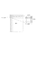
<画像形成装置10(図2)>
画像形成装置10の外観を図2に示す。スキャナ部13は、複数のCCDを有している。この各CCDの感度が夫々異なっていると、たとえ原稿上の各画素の濃度が同じであったとしても、各画素が夫々違う濃度であると認識されてしまう。そのため、スキャナ部では、最初に白板(一様に白い板)を露光走査し、露光走査して得られた反射光の量を電気信号に変換してコントローラ11に出力している。なお、後述するように、コントローラ11内のシェーディング補正部500は、各CCDから得られた電気信号を元に、各CCDの感度の違いを認識している。そして、この認識された感度の違いを利用して、原稿上の画像をスキャンして得られた電気信号の値を補正している。さらに、シェーディング補正部500は、後述するコントローラ11内のCPU301からゲイン調整の情報を受取ると、当該情報に応じたゲイン調整を行う。ゲイン調整は、原稿を露光走査して得られた電気信号の値を、どのように0〜255の輝度信号値に割り付けるかを調整するために用いられる。このゲイン調整により、原稿を露光走査して得られた電気信号の値を高い輝度信号値に変換したり、低い輝度信号値に変換したりすることができるようになっている。続いて、この原稿上の画像をスキャンする構成について説明する。
<Image Forming Apparatus 10 (FIG. 2)>
An appearance of the
スキャナ部は、原稿上の画像を露光走査して得られた反射光をCCDに入力することで画像の情報を電気信号に変換する。さらに電気信号をR,G,B各色からなる輝度信号に変換し、当該輝度信号を画像データとしてコントローラ11に対して出力する。 The scanner unit converts the image information into an electrical signal by inputting the reflected light obtained by exposing and scanning the image on the document to the CCD. Further, the electric signal is converted into a luminance signal composed of R, G, and B colors, and the luminance signal is output to the controller 11 as image data.
なお、原稿は原稿フィーダ201のトレイ202にセットされる。ユーザが操作部12から読み取り開始を指示すると、コントローラ11からスキャナ部13に原稿読み取り指示が与えられる。スキャナ部13は、この指示を受けると原稿フィーダ201のトレイ202から原稿を1枚ずつフィードして、原稿の読み取り動作を行う。なお、原稿の読み取り方法は原稿フィーダ201による自動送り方式ではなく、原稿を不図示のガラス面上に載置し露光部を移動させることで原稿の走査を行う方法であってもよい。
The document is set on the
プリンタ部14は、コントローラ11から受取った画像データを用紙上に形成する画像形成デバイスである。なお、本実施例において画像形成方式は感光体ドラムや感光体ベルトを用いた電子写真方式となっているが、本発明はこれに限られることはない。例えば、微少ノズルアレイからインクを吐出して用紙上に印字するインクジェット方式などでも適用可能である。また、プリンタ部14には、異なる用紙サイズ又は異なる用紙向きを選択可能とする複数の用紙カセット203、204、205が設けられている。排紙トレイ206には印字後の用紙が排出される。
The
<コントローラ11の詳細説明(図3)>
図3は、画像形成装置10のコントローラ11の構成をより詳細に説明するためのブロック図である。
<Detailed Description of Controller 11 (FIG. 3)>
FIG. 3 is a block diagram for explaining the configuration of the controller 11 of the
コントローラ11はスキャナ部13やプリンタ部14と電気的に接続されており、一方ではLAN50やWAN331を介してPC40や外部の装置などと接続されている。これにより画像データやデバイス情報の入出力が可能となっている。
The controller 11 is electrically connected to the
CPU301は、ROM303に記憶された制御プログラム等に基づいて接続中の各種デバイスとのアクセスを統括的に制御すると共に、コントローラ内部で行われる各種処理についても統括的に制御する。RAM302は、CPU301が動作するためのシステムワークメモリであり、かつ画像データを一時記憶するためのメモリでもある。このRAM302は、記憶した内容を電源off後も保持しておくSRAM及び電源off後には記憶した内容が消去されてしまうDRAMにより構成されている。ROM303には装置のブートプログラムなどが格納されている。HDD304はハードディスクドライブであり、システムソフトウェアや画像データを格納することが可能となっている。
The CPU 301 comprehensively controls access to various connected devices based on a control program stored in the
操作部I/F305は、システムバス310と操作部12とを接続するためのインターフェース部である。この操作部I/F305は、操作部12に表示するための画像データをシステムバス310から受取り操作部12に出力すると共に、操作部12から入力された情報をシステムバス310へと出力する。
The operation unit I /
NetworkI/F306はLAN50及びシステムバス310に接続し、情報の入出力を行う。Modem307はWAN331及びシステムバス310に接続しており、情報の入出力を行う。2値画像回転部308は送信前の画像データの方向を変換する。2値画像圧縮・伸張部309は、送信前の画像データの解像度を所定の解像度や相手能力に合わせた解像度に変換する。なお圧縮及び伸張にあたってはJBIG、MMR、MR、MHなどの方式が用いられる。画像バス330は画像データをやり取りするための伝送路であり、PCIバス又はIEEE1394で構成されている。
A network I / F 306 is connected to the LAN 50 and the system bus 310 to input / output information. The Modem 307 is connected to the
スキャナ画像処理部312は、スキャナ部13からスキャナI/F311を介して受取った画像データに対して、補正、加工、及び編集を行う。なお、スキャナ画像処理部312は、受取った画像データがカラー原稿か白黒原稿かや、文字原稿か写真原稿かなどを判定する。そして、その判定結果を画像データに付随させる。こうした付随情報を属性データと称する。このスキャナ画像処理部312で行われる処理の詳細については後述する。
The scanner
圧縮部313は画像データを受取り、この画像データを32画素x32画素のブロック単位に分割する。なお、この32×32画素の画像データをタイルデータと称する。図4は、このタイルデータを概念的に表している。原稿(読み取り前の紙媒体)において、このタイルデータに対応する領域をタイル画像と称する。なおタイルデータには、その32×32画素のブロックにおける平均輝度情報やタイル画像の原稿上の座標位置がヘッダ情報として付加されている。さらに圧縮部313は、複数のタイルデータからなる画像データを圧縮する。伸張部316は、複数のタイルデータからなる画像データを伸張した後にラスタ展開してプリンタ画像処理部315に送る。
The
プリンタ画像処理部315は、伸張部316から送られた画像データを受取り、この画像データに付随させられている属性データを参照しながら画像データに画像処理を施す。画像処理後の画像データは、プリンタI/F314を介してプリンタ部14に出力される。このプリンタ画像処理部315で行われる処理の詳細については後述する。
The printer image processing unit 315 receives the image data sent from the decompression unit 316 and performs image processing on the image data while referring to attribute data attached to the image data. The image data after the image processing is output to the
画像変換部317は、画像データに対して所定の変換処理を施す。この処理部は以下に示すような処理部により構成される。 The image conversion unit 317 performs a predetermined conversion process on the image data. This processing unit is composed of the following processing units.
伸張部318は受取った画像データを伸張する。圧縮部319は受取った画像データを圧縮する。回転部320は受取った画像データを回転する。変倍部321は受取った画像データに対し解像度変換処理(例えば600dpiから200dpi)を行う。色空間変換部322は受取った画像データの色空間を変換する。この色空間変換部322は、マトリクス又はテーブルを用いて公知の下地飛ばし処理を行ったり、公知のLOG変換処理(RGB→CMY)を行ったり、公知の出力色補正処理(CMY→CMYK)を行ったりすることができる。2値多値変換部323は受取った2階調の画像データを256階調の画像データに変換する。逆に多値2値変換部324は受取った256階調の画像データを誤差拡散処理などの手法により2階調の画像データに変換する。
A
合成部327は受取った2つの画像データを合成し1枚の画像データを生成する。なお、2つの画像データを合成する際には、合成対象の画素同士が持つ輝度値の平均値を合成輝度値とする方法や、輝度レベルで明るい方の画素の輝度値を合成後の画素の輝度値とする方法が適用される。また、暗い方を合成後の画素とする方法の利用も可能である。さらに合成対象の画素同士の論理和演算、論理積演算、排他的論理和演算などで合成後の輝度値を決定する方法なども適用可能である。これらの合成方法はいずれも周知の手法である。間引き部326は受取った画像データの画素を間引くことで解像度変換を行い、1/2,1/4,1/8などの画像データを生成する。移動部325は受取った画像データに余白部分をつけたり余白部分を削除したりする。 The synthesizer 327 synthesizes the received two pieces of image data to generate one piece of image data. When combining two pieces of image data, a method of using an average value of luminance values of pixels to be combined as a combined luminance value, or a luminance value of a pixel having a brighter luminance level, A method for obtaining a luminance value is applied. In addition, it is possible to use a method in which the darker pixel is used as a synthesized pixel. Furthermore, a method of determining a luminance value after synthesis by a logical sum operation, a logical product operation, an exclusive logical sum operation, or the like between pixels to be synthesized is also applicable. These synthesis methods are all well-known methods. The thinning unit 326 performs resolution conversion by thinning out the pixels of the received image data, and generates image data such as 1/2, 1/4, and 1/8. The moving unit 325 adds a margin part to the received image data or deletes the margin part.
RIP328は、PC40などから送信されたPDLコードデータを元に生成された中間データを受取り、ビットマップデータ(多値)を生成する。
The
<スキャナ画像処理部312の詳細説明(図5)>
図5にスキャナ画像処理部312の内部構成を示す。
スキャナ画像処理部312はRGB各8bitの輝度信号からなる画像データを受取る。
<Detailed Description of Scanner Image Processing Unit 312 (FIG. 5)>
FIG. 5 shows an internal configuration of the scanner
The scanner
シェーディング補正部500は、この輝度信号に対してシェーディング補正する。シェーディング補正とは、上述したように、CCDの感度のばらつきによって原稿の明るさが誤認識されてしまうことを防止するための処理である。さらに、上述したように、このシェーディング補正部500は、CPU301からの指示によりゲイン調整を行うことができるようになっている。 The shading correction unit 500 performs shading correction on the luminance signal. As described above, the shading correction is a process for preventing the brightness of the document from being erroneously recognized due to variations in CCD sensitivity. Further, as described above, the shading correction unit 500 can perform gain adjustment according to an instruction from the CPU 301.
続いて、この輝度信号は、マスキング処理部501によりCCDのフィルタ色に依存しない標準的な輝度信号に変換される。
Subsequently, the luminance signal is converted into a standard luminance signal that does not depend on the CCD filter color by the masking
フィルタ処理部502は、受取った画像データの空間周波数を任意に補正する。この処理部は、受取った画像データに対して、例えば7×7のマトリクスを用いた演算処理を行う。ところで、複写機や複合機では、図7における704タブの押し下げによりコピーモードとして文字モードや写真モードや文字/写真モードを選択することができる。ここでユーザにより文字モードが選択された場合には、フィルタ処理部502は文字用のフィルタを画像データ全体にかける。また、写真モードが選択された場合には、写真用のフィルタを画像データ全体にかける。また、文字/写真モードが選択された場合には、後述の文字写真判定信号(属性データの一部)に応じて画素ごとに適応的にフィルタを切り替える。つまり、画素ごとに写真用のフィルタをかけるか文字用のフィルタをかけるかが決定される。なお、写真用のフィルタには高周波成分のみ平滑化が行われるような係数が設定されている。これは、画像のざらつきを目立たせないためである。また、文字用のフィルタには強めのエッジ強調を行うような係数が設定されている。これは、文字のシャープさを出すためである。
The
ヒストグラム生成部503は、受取った画像データを構成する各画素の輝度データをサンプリングする。より詳細に説明すると、主走査方向、副走査方向にそれぞれ指定した開始点から終了点で囲まれた矩形領域内の輝度データを、主走査方向、副走査方向に一定のピッチでサンプリングする。そして、サンプリング結果を元にヒストグラムデータを生成する。生成されたヒストグラムデータは、下地飛ばし処理を行う際に下地レベルを推測するために用いられる。入力側ガンマ補正部504は、テーブル等を利用して非線形特性を持つ輝度データに変換する。 The histogram generation unit 503 samples the luminance data of each pixel constituting the received image data. More specifically, luminance data in a rectangular area surrounded by a start point and an end point specified in the main scanning direction and the sub scanning direction are sampled at a constant pitch in the main scanning direction and the sub scanning direction. Then, histogram data is generated based on the sampling result. The generated histogram data is used to estimate the background level when performing background removal processing. The input-side gamma correction unit 504 converts luminance data having nonlinear characteristics using a table or the like.
カラーモノクロ判定部505は、受取った画像データを構成する各画素が有彩色であるか無彩色であるかを判定し、その判定結果をカラーモノクロ判定信号(属性データの一部)として画像データに付随させる。
A color /
文字写真判定部506は、画像データを構成する各画素が文字を構成する画素なのか、網点を構成する画素なのか、網点中の文字を構成する画素なのか、ベタ画像を構成する画素なのかを各画素の画素値と各画素の周辺画素の画素値とに基づいて判定する。なお、どれにもあてはまらない画素は、白領域を構成している画素である。そして、その判定結果を文字写真判定信号(属性データの一部)として画像データに付随させる。
The character
紙指紋情報取得部507は、シェーディング補正部500から入力されたRGBの画像データのうち紙指紋情報取得領域として適切な領域を決定し、当該決定された紙指紋情報取得領域の画像データを取得する。なお、紙指紋情報取得領域として適切な領域を決定する方法については、図13、図15を用いて後述する。 The paper fingerprint information acquisition unit 507 determines an appropriate region as the paper fingerprint information acquisition region from the RGB image data input from the shading correction unit 500, and acquires the image data of the determined paper fingerprint information acquisition region. . A method for determining an appropriate area as the paper fingerprint information acquisition area will be described later with reference to FIGS.
図8は、この紙指紋情報取得部507が行う紙指紋情報取得処理を示すフローチャートである。
ステップ801では紙指紋情報取得部507において取得した画像データをグレイスケールの画像データに変換する。ステップ802では、ステップ801においてグレイスケールの画像データへ変換された画像において、印刷や手書きの文字といった誤判定の要因となりうるものを取り除いて照合を行うためのマスクデータを作成する。マスクデータは“0”or“1”の2値データである。グレイスケールの画像データにおいて、輝度信号値が第1の閾値(つまり、明るい)以上である画素については、マスクデータの値を“1”に設定する。また、輝度信号値が第1の閾値未満である画素についてはマスクデータの値を“0”に設定する。以上の処理を、グレイスケールの画像データに含まれる各画素に対して行う。ステップ803では、ステップ801においてグレイスケールに変換された画像データ及び、ステップ802において作成されたマスクデータの2つのデータを紙指紋情報として取得する。なお、ステップ801においてグレイスケールに変換された画像データ自体のことを紙指紋情報と称することもあるが、本実施例では、上記二つのデータを紙指紋情報と称することにする。
FIG. 8 is a flowchart showing a paper fingerprint information acquisition process performed by the paper fingerprint information acquisition unit 507.
In
紙指紋情報取得部507は、上記紙指紋情報取得領域の紙指紋情報を不図示のデータバスを用いてRAM302に送る。 The paper fingerprint information acquisition unit 507 sends the paper fingerprint information in the paper fingerprint information acquisition area to the RAM 302 using a data bus (not shown).
<プリンタ画像処理部315の詳細説明(図6)>
図6にプリンタ画像処理315においてなされる処理の流れを示す。
下地飛ばし処理部601は、スキャナ画像処理部312で生成されたヒストグラムを用いて画像データの下地色を飛ばす(除去する)。モノクロ生成部602はカラーデータをモノクロデータに変換する。Log変換部603は輝度濃度変換を行う。このLog変換部603は、例えば、RGB入力された画像データを、CMYの画像データに変換する。出力色補正部604は出力色補正を行う。例えばCMY入力された画像データを、テーブルやマトリックスを用いてCMYKの画像データに変換する。出力側ガンマ補正部605は、この出力側ガンマ補正部605に入力される信号値と、複写出力後の反射濃度値とが比例するように補正を行う。中間調補正部606は、出力するプリンタ部の階調数に合わせて中間調処理を行う。例えば、受取った高階調の画像データに対し2値化や32値化などを行う。
<Detailed Description of Printer Image Processing Unit 315 (FIG. 6)>
FIG. 6 shows the flow of processing performed in the printer image processing 315.
The background
なお、スキャナ画像処理部312やプリンタ画像処理部315における各処理部では、受取った画像データに各処理を施さずに出力させることも可能となっている。このような、ある処理部において処理を施さずにデータを通過させることを、以下では「処理部をスルーさせる」と表現することにする。
Each processing unit in the scanner
<紙指紋情報登録処理>
CPU301は、紙指紋情報取得部507からRAM302に送られてきた所定領域の紙指紋情報を読出し、当該読出された紙指紋情報を不図示のサーバに登録することが可能となっている。この登録は、RAM302内に格納されたプログラムを実行することによって行われる。
<Paper fingerprint information registration process>
The CPU 301 can read the paper fingerprint information in a predetermined area sent from the paper fingerprint information acquisition unit 507 to the RAM 302 and register the read paper fingerprint information in a server (not shown). This registration is performed by executing a program stored in the RAM 302.
<紙指紋情報照合処理>
CPU301は、紙指紋情報取得部507からRAM302に送られてきた紙指紋情報を読出し、当該読出された紙指紋情報と他の紙指紋情報とを照合すべく制御することが可能となっている。なお、他の紙指紋情報は、本実施例においてサーバに登録されている紙指紋情報のことを意味する。
<Paper fingerprint information matching process>
The CPU 301 can read out the paper fingerprint information sent from the paper fingerprint information acquisition unit 507 to the RAM 302, and can control the read paper fingerprint information with other paper fingerprint information. The other paper fingerprint information means paper fingerprint information registered in the server in this embodiment.
図9は、この紙指紋情報照合処理を示すフローチャートである。本フローチャートの各ステップは、CPU301により統括的に制御される。
ステップ901では、サーバに登録されている紙指紋情報をRAM302から取出す。
FIG. 9 is a flowchart showing the paper fingerprint information matching process. Each step of this flowchart is centrally controlled by the CPU 301.
In
ステップ902では、紙指紋情報取得部507から送られてきた(登録されていた)紙指紋情報と、ステップ901において取出された(今、取出されたばかりの)紙指紋情報との照合をする。照合にあたっては、まず、登録されていた紙指紋情報と取出された紙指紋情報とが夫々異なった位置から取得された可能性があることを懸念して、位置ずれ補正を行う。この位置ずれ補正は以下のような手法となっている。
In
<位置ずれ補正>
まず、式(1)を用いて2つの紙指紋情報の誤差値E(i,j)(2つの紙指紋情報の位置を(i,j)ずらしたときの)を(2n−1)×(2m−1)個求める。
<Position correction>
First, the error value E (i, j) of two pieces of paper fingerprint information (when the positions of the two pieces of paper fingerprint information are shifted by (i, j)) is expressed by (2n−1) × ( 2m-1) is obtained.

式(1)においてα1はステップ901で取出された(登録されていた)紙指紋情報中のマスクデータである。f1はステップ901で取出された(登録されていた)紙指紋情報中のグレイスケール画像データである。α2はステップ902で紙指紋情報取得部507から送られてきた(今、取出されたばかりの)紙指紋情報中のマスクデータである。f2はステップ902で紙指紋情報取得部507から送られてきた(今、取出されたばかりの)紙指紋情報中のグレイスケール画像データである。
In equation (1), α 1 is mask data in the paper fingerprint information extracted (registered) in
具体的な方法を図19,20、21、22を用いて説明する。図19は、それぞれ登録されている紙指紋情報と今回得られた紙指紋情報のイメージ図を表す。それぞれ、横n画素、縦m画素から構成されているものとする。 A specific method will be described with reference to FIGS. FIG. 19 shows an image diagram of the registered paper fingerprint information and the paper fingerprint information obtained this time. Assume that each pixel is composed of horizontal n pixels and vertical m pixels.
式(1)に示した関数において、i,jをそれぞれ−n+1〜n−1、−m+1〜m−1の範囲でそれぞれ1画素毎にずらし、登録されていた紙指紋情報と今回得られたばかりの紙指紋情報の誤差値E(i,j)を(2n−1)×(2m−1)個求める。即ち、E(−n+1,−m+1)〜E(n−1,m−1)を求める。
In the function shown in Expression (1), i and j are shifted by 1 pixel in the range of −
図20(A)は、登録されている紙指紋情報の左上1画素に対して、今回得られた紙指紋情報の右下1画素だけ重なっているイメージ図を表す。この状態において、式(1)の関数により求まる値をE(−n+1,−m+1)とする。図20(B)は、図20(A)よりも今回得られた紙指紋情報を右に1画素分だけ移動したイメージ図を表す。この状態において、式(1)の関数により求まる値をE(−n+2,−m+1)とする。同様に今回得られたばかりの紙指紋情報を移動させながら演算を行う。図20(C)では、今回得られたばかりの紙指紋情報を、登録されていた紙指紋情報と重なるところまで移動させており、これによりE(0,−(m−1))が求まる。さらに、図20(D)では、今回得られた紙指紋情報を右端まで移動して、E(n−1,−m+1)を求める。このように、横方向にずらすと、E(i,j)のうちのiが1づつ加算される。
FIG. 20A shows an image diagram in which the upper left pixel of the registered paper fingerprint information is overlapped by the lower right pixel of the obtained paper fingerprint information. In this state, the value obtained by the function of Expression (1) is E (−
同様に図21(A)では、図20(A)よりも、縦方向である下に1画素だけ今回得られた紙指紋情報を移動して、E(−n+1,−m+2)の値を求める。
Similarly, in FIG. 21A, the paper fingerprint information obtained this time by one pixel is moved downward in the vertical direction as compared with FIG. 20A, and the value of E (−
さらに図21(B)は、図21(A)に対して、今回得られた紙指紋情報を右端まで移動してE(n−1,−m+2)の値を求める。 Further, in FIG. 21B, the value of E (n−1, −m + 2) is obtained by moving the paper fingerprint information obtained this time to the right end with respect to FIG.
図22(A)は、登録されている紙指紋情報と今回得られた紙指紋情報が,同じ位置の場合を表し、このときのE(i,j)の値をE(0,0)とする。
同様に、それぞれの紙指紋情報が少なくとも1画素以上重なるように画像をずらしながら演算を行う。最後に図22(B)のように、E(n−1,m−1)を求める。
このようにして、(2n−1)×(2m−1)個の誤差値E(i,j)の集合を求める。
FIG. 22A shows the case where the registered paper fingerprint information and the paper fingerprint information obtained this time are at the same position, and the value of E (i, j) at this time is expressed as E (0,0). To do.
Similarly, the calculation is performed while shifting the images so that each paper fingerprint information overlaps at least one pixel. Finally, as shown in FIG. 22B, E (n−1, m−1) is obtained.
In this way, a set of (2n−1) × (2m−1) error values E (i, j) is obtained.
ここで、この式(1)の意味を考えるために、i=0,j=0であり、かつ、α1(x,y)=1(ただし、x=0〜n,y=0〜m)であり、かつ、α2(x−i,y−j)=1(ただし、x=0〜n,y=0〜m)の場合を考えてみることにする。つまり、α1(x,y)=1(ただし、x=0〜n,y=0〜m)であり、かつ、α2(x−i,y−j)=1(ただし、x=0〜n,y=0〜m)の場合のE(0,0)を求めることにする。 Here, in order to consider the meaning of the equation (1), i = 0, j = 0, and α 1 (x, y) = 1 (where x = 0 to n, y = 0 to m ) And α 2 (x−i, y−j) = 1 (where x = 0 to n and y = 0 to m). That is, α 1 (x, y) = 1 (where x = 0 to n, y = 0 to m), and α 2 (xi, y−j) = 1 (where x = 0). E (0,0) in the case of .about.n, y = 0 to m).
なお、i=0,j=0とは、図22(A)のように、登録されていた紙指紋情報と今回得られた紙指紋情報が同じ位置であることを示す。 Note that i = 0 and j = 0 indicate that the registered paper fingerprint information and the paper fingerprint information obtained this time are at the same position as shown in FIG.
ここで、α1(x,y)=1(ただし、x=0〜n,y=0〜m)は、登録されていた紙指紋情報の全ての画素が明るいことを示す。言い換えると、登録されていた紙指紋情報が取得された際には、紙指紋取得領域上には一切トナーやインクなどの色材やゴミがのっていなかったことを示す。 Here, α 1 (x, y) = 1 (where x = 0 to n, y = 0 to m) indicates that all pixels of the registered paper fingerprint information are bright. In other words, when the registered paper fingerprint information is acquired, it indicates that no color material such as toner or ink or dust has been placed on the paper fingerprint acquisition area.
また、α2(x−i,y−j)=1(ただし、x=0〜n,y=0〜m)は、今回取得した紙指紋情報の全ての画素が明るいことを示す。言い換えると、今取得されたばかりの紙指紋情報が取得された際には、紙指紋取得領域上には一切トナーやインクなどの色材やゴミがのっていなかったことを示す。 Further, α 2 (x−i, y−j) = 1 (where x = 0 to n, y = 0 to m) indicates that all pixels of the paper fingerprint information acquired this time are bright. In other words, when the paper fingerprint information just acquired is acquired, it indicates that no color material such as toner or ink or dust is on the paper fingerprint acquisition area.
このように、α1(x,y)=1とα2(x−i,y−j)=1とが全ての画素において成り立つ時、(1)式は、 Thus, when α 1 (x, y) = 1 and α 2 (x−i, y−j) = 1 hold in all pixels, the equation (1) becomes
この{f1(x,y)−f2(x,y)}2は、登録されていた紙指紋情報中のグレイスケール画像データと、今取出されたばかりの紙指紋情報中のグレイスケール画像データとの差の二乗値を示す。従って、この(1)式は、二つの紙指紋情報同士の各画素における差の二乗を合計したものになる。つまり、f1(x,y)とf2(x,y)とが似ている画素が多ければ多いほど、このE(0,0)は、小さな値を取ることになる。 This {f 1 (x, y) −f 2 (x, y)} 2 is the gray scale image data in the registered paper fingerprint information and the gray scale image data in the paper fingerprint information just extracted. The square value of the difference between Therefore, this equation (1) is the sum of the squares of the differences in each pixel between the two pieces of paper fingerprint information. That is, the more pixels f 1 (x, y) and f 2 (x, y) are similar, the smaller this E (0, 0) will be.
以上説明したのは、E(0,0)の求め方であるが、同じようにして他のE(i,j)を求めていく。ちなみに、f1(x,y)とf2(x,y)とが似ている画素が多ければ多いほどE(i,j)が小さな値を取ることから、
E(k,l)=min{E(i,j)}である場合、登録されていた紙指紋情報を取得した際の位置と、今取得されたばかりの紙指紋情報を取得した際の位置とは、互いにk,lずれていたことがわかる。
What has been described above is how to obtain E (0,0), but other E (i, j) are obtained in the same manner. Incidentally, since E (i, j) takes a smaller value as the number of pixels in which f 1 (x, y) and f 2 (x, y) are similar is larger,
If E (k, l) = min {E (i, j)}, the position when the registered paper fingerprint information is acquired, and the position when the paper fingerprint information just acquired is acquired It can be seen that they were shifted from each other by k and l.
<αの意義>
式(1)の分子は、{f1(x,y)−f2(x−i,y−j)}2に対してα1とα2とがかけられた結果を意味する(正確には、さらにΣ記号により合計値が求められている)。このα1とα2は、濃い色の画素は0、薄い色の画素は1を示す。
<Significance of α>
The numerator of formula (1) means the result of multiplying {f 1 (x, y) -f 2 (xi, yj)} 2 by α 1 and α 2 (exactly Is further determined by the Σ symbol). Α 1 and α 2 indicate 0 for a dark pixel and 1 for a light pixel.
従って、α1とα2とのうちどちらか一方(又は両方)が0の場合には、α1α2{f1(x,y)−f2(x−i,y−j)}2は0になることになる。 Accordingly, when one (or both) of α 1 and α 2 is 0, α 1 α 2 {f 1 (x, y) −f 2 (xi, y−j)} 2 Will be 0.
即ち、どちらか一方(または両方)の紙指紋情報において対象とする画素が濃い色であった場合には、その画素における濃度差は考慮しないことを示している。これは、ゴミや色材がのってしまった画素を無視するためである。 That is, when one or both (or both) of the paper fingerprint information has a dark pixel, the density difference between the pixels is not considered. This is for ignoring pixels on which dust or color material has been placed.
この処理により、Σ記号により合計する数が増減するため、総数Σα1(x,y)α2(x−i,y−j)で割ることで正規化を行う。なお、式(1)の分母にあるΣα1(x,y)α2(x−i,y−j)が0になる誤差値E(i,j)は、後述の誤差値の集合(E(−(n−1),−(m−1))〜E(n−1,m−1))には含めないものとする。 As a result of this processing, the total number increases or decreases depending on the Σ symbol, so normalization is performed by dividing by the total number Σα 1 (x, y) α 2 (xi, y−j). Note that an error value E (i, j) in which Σα 1 (x, y) α 2 (x−i, y−j) in the denominator of Expression (1) becomes 0 is a set of error values (E (-(N-1),-(m-1)) to E (n-1, m-1)) are not included.
<マッチング度合いの決定方法>
上述したように、E(k,l)=min{E(i,j)}である場合、登録されていた紙指紋情報を取得した際の位置と、今取得されたばかりの紙指紋情報を取得した際の位置とは互いにk,lずれていたことがわかる。
<Determination method of matching degree>
As described above, when E (k, l) = min {E (i, j)}, the position when the registered paper fingerprint information is acquired and the paper fingerprint information just acquired are acquired. It can be seen that the positions were shifted by k and l from each other.
続いて、二つの紙指紋情報がどれだけ似ているのかを示す値(この値を、マッチング度合いと称する)を、そのE(k,l)及び他のE(i,j)を使って求める。 Subsequently, a value indicating how much the two pieces of paper fingerprint information are similar (this value is referred to as a matching degree) is obtained using the E (k, l) and other E (i, j). .
まず、(1)の関数により求まった誤差値の集合(例えば、E(0,0)=10※,E(0,1)=50,E(1,0)=50,E(1,1)=50)から平均値(40)を求める。・・・(A)
なお、※は、値とは関係がない。注目して頂くために記載しただけである。注目して頂きたかった理由は後述する。
First, a set of error values obtained by the function of (1) (for example, E (0,0) = 10 *, E (0,1) = 50, E (1,0) = 50, E (1,1 ) = 50) to obtain the average value (40). ... (A)
Note that * is not related to the value. They are listed only for your attention. The reason I wanted to pay attention will be described later.
次に、平均値(40)から各誤差値(10※,50,50,50)を引いて、新たな集合(30※,−10,−10,−10)を求める。・・・・(B)
そして、この新たな集合から標準偏差(30×30+10×10+10×10+10×10=1200,1200/4=300,√300=10√3=約17)を求める。そして、上記新たな集合を17で割り、商を求める(1※,−1,−1,−1)。・・・・(C)
そして、求められた値のうちの最大値をマッチング度合い(1※)とする。なお、この1※という値は、E(0,0)=10※という値と対応した値である。E(0,0)というのは、今回の場合、E(0,0)=min{E(i,j)}を満たす値である。
Next, each error value (10 *, 50, 50, 50) is subtracted from the average value (40) to obtain a new set (30 *, −10, −10, −10). .... (B)
Then, a standard deviation (30 × 30 + 10 × 10 + 10 × 10 + 10 × 10 = 1200, 1200/4 = 300, √300 = 10√3 = about 17) is obtained from this new set. Then, the new set is divided by 17 to obtain a quotient (1 *, -1, -1, -1). .... (C)
And let the maximum value of the calculated | required values be a matching degree (1 *). The
<マッチング度合いの決定方法の概念的な説明>
上記マッチング度合いの決定方法を行う処理は、結局、複数の誤差値集合の中で最も小さな誤差値が、平均的な誤差値とどれだけ離れているかを計算する(A及びB)。
<Conceptual explanation of how to determine the degree of matching>
The process of performing the matching degree determination method eventually calculates how far the smallest error value in the plurality of error value sets is from the average error value (A and B).
そして、その離れ具合を標準偏差で割ることでマッチング度合いを求める(C)。
最後にマッチング度合いを閾値と比較することで、照合結果を得る(D)。
Then, the degree of matching is obtained by dividing the degree of separation by the standard deviation (C).
Finally, a matching result is obtained by comparing the matching degree with a threshold (D).
なお、標準偏差は、「各誤差値と平均値との差」の平均的な値を意味する。言い換えると、標準偏差は、集合の中で大体どれくらいのばらつきが全体的に生じているかを示す値である。 The standard deviation means an average value of “difference between each error value and the average value”. In other words, the standard deviation is a value indicating how much variation occurs in the entire set.
このような全体的なばらつき値で上記離れ具合を割ることで、min{E(i,j)}が集合E(i,j)の中でどれだけ小さいか(突出して小さいか、ちょっと小さいか)がわかることになる。 By dividing the above degree of separation by such an overall variation value, how small is min {E (i, j)} in the set E (i, j) (projectingly small or slightly small) ) Will be understood.
そして、min{E(i,j)}が集合E(i,j)の中で非常に突出して小さい場合に有効と判断し、それ以外の場合に無効と判断する(D)。 Then, it is determined to be valid when min {E (i, j)} is very prominent and small in the set E (i, j), and is invalid otherwise (D).
<min{E(i,j)}が集合E(i,j)の中で非常に突出して小さい場合のみ有効と判断する理由>
ここで、登録されていた紙指紋情報と、今取得されたばかりの紙指紋情報とが、同じ紙から取得されたと仮定する。
<Reason why min {E (i, j)} is determined to be effective only when it is very small in the set E (i, j)>
Here, it is assumed that the registered paper fingerprint information and the paper fingerprint information just acquired are acquired from the same paper.
すると、登録されていた紙指紋情報と、今取得されたばかりの紙指紋情報とが極めて一致する場所(ずれ位置)があるはずである。この時、このずれ位置では、登録されていた紙指紋情報と、今取得されたばかりの紙指紋情報とが極めて一致するため、E(i,j)は非常に小さくなるはずである。 Then, there should be a place (shift position) where the registered paper fingerprint information and the paper fingerprint information just acquired are very consistent. At this time, at this misalignment position, the registered paper fingerprint information and the paper fingerprint information just acquired are very coincident, so E (i, j) should be very small.
一方、このずれ位置から少しでもずらすと、登録されていた紙指紋情報と今取得されたばかりの紙指紋情報には何ら関連性がなくなる。従って、E(i,j)は通常の大きな値になるはずである。 On the other hand, if the position is slightly shifted from this position, the registered paper fingerprint information and the paper fingerprint information just acquired are no longer relevant. Therefore, E (i, j) should be a normal large value.
そのため、「二つの紙指紋情報が同じ紙から取得された」という条件は、「最も小さなE(i,j)が集合E(i,j)の中で突出して小さい」という条件と一致する。 Therefore, the condition that “two pieces of paper fingerprint information are acquired from the same paper” matches the condition that “the smallest E (i, j) protrudes and is small in the set E (i, j)”.
<紙指紋情報照合処理>に話を戻す。
ステップ903では、ステップ902において求められた2つの紙指紋情報のマッチング度合いと所定の閾値との比較を行って、「有効」「無効」を決定する。なお、マッチング度合いのことを類似度と称することもある。また、マッチング度合いと所定の閾値との比較結果のことを、照合結果と称することもある。
コントローラ11の説明は以上である。
Return to <Paper fingerprint information collation processing>.
In step 903, the matching degree of the two pieces of paper fingerprint information obtained in
The description of the controller 11 has been described above.
<操作画面の説明>
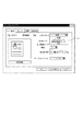
図7は画像形成装置10における初期画面である。領域701は、画像形成装置10がコピーできる状態にあるか否かを示し、かつ設定したコピー部数を示す。原稿選択タブ704は原稿のタイプを選択するためのタブであり、このタブが押し下げられると文字、写真、文字/写真モードの3種類の選択メニューをポップアップ表示される。フィニッシングタブ706は各種フィニッシングに関わる設定を行うためのタブである。両面設定タブ707は両面読込み及び両面印刷に関する設定を行うためのタブである。読み取りモードタブ702は原稿の読み取りモードを選択するためのタブである。このタブが押し下げられるとカラー/ブラック/自動(ACS)の3種類の選択メニューがポップアップ表示される。なお、カラーが選択された場合にはカラーコピーが、ブラックが選択された場合にはモノクロコピーが行われる。また、ACSが選択された場合には、上述したモノクロカラー判定信号によりコピーモードが決定される。
<Explanation of operation screen>
FIG. 7 shows an initial screen in the
領域708は、紙指紋情報登録処理を選択するためのタブである。紙指紋情報登録処理については、後述する。領域709は、紙指紋情報照合処理を選択するためのタブである。この紙指紋情報照合処理については、後述する。
An area 708 is a tab for selecting a paper fingerprint information registration process. The paper fingerprint information registration process will be described later. An
領域710はシステムの状況を示すためのタブである。このタブが押し下げられると、画像形成装置10内のHDD304に保存されている画像データの一覧が表示画面に表示されるようになっている。
An
<紙指紋情報登録処理のタブが押下された際の動作(コピー時の紙指紋情報登録処理)>
続いて、図7に示す紙指紋情報登録タブ708がユーザにより押下された後にスタートキーが押下された際に、実行される紙指紋情報登録処理について図16を用いて説明する。
<Operation when paper fingerprint information registration process tab is pressed (paper fingerprint information registration process at the time of copying)>
Next, a paper fingerprint information registration process executed when the user presses the paper fingerprint information registration tab 708 shown in FIG. 7 and then presses the start key will be described with reference to FIG.
ステップ1601では、CPU301は、スキャナ部13で読み取られた原稿を、画像データとしてスキャナI/F311を介してスキャナ画像処理部312に送るように制御する。
In step 1601, the CPU 301 controls the document read by the
ステップ1602では、スキャナ画像処理部312は、一般的なゲイン調整値よりも小さいゲイン調整値を、シェーディング補正部500に設定する。そして、画像データに対して上記小さいゲイン調整値を適用することで得られた各輝度信号値を紙指紋情報取得部507に対して出力する。その後、出力データに基づいて、紙指紋情報取得部507は、紙指紋情報を取得する。そして、当該取得された紙指紋情報を不図示のデータバスを用いてRAM302に送る。
In
紙指紋取得技術では、白い領域から繊維のパターンを取得する以上、暗めの画像データを得ることは必須である。そのため、本実施例では、スキャナ画像処理部312が一般的なゲイン調整値よりも小さいゲイン調整値を設定することで、紙指紋情報取得用の暗い画像データを得た。しかしながら、暗い画像データを得る方法としてはこれに限られない。例えば、光量を落としてスキャンするような方法も考えられる。
In the paper fingerprint acquisition technology, it is essential to obtain dark image data as long as the fiber pattern is acquired from the white area. Therefore, in this embodiment, the scanner
ステップ1603では、CPU301は、サーバから管理番号を発行してもらい、当該管理番号と紙指紋情報と紙指紋情報取得領域の情報とを夫々関連付けてサーバに登録する。なお、紙指紋情報取得領域の情報とは、どこから紙指紋情報を取得したかを示す位置情報のことである。
In
ステップ1604では、管理番号を表示画面に表示するようにCPU301は制御する。
In
<紙指紋情報照合処理のタブが押下された際の動作>
続いて、図7に示す紙指紋情報照合タブ709がユーザにより押下され、その後、管理番号が入力された後にスタートキーが押下された際の動作について図17を用いて説明する。
<Operation when paper fingerprint information matching tab is pressed>
Next, an operation when the paper fingerprint
ステップ1701では、CPU301は、スキャナ部13で読み取られた原稿を、画像データとしてスキャナI/F311を介してスキャナ画像処理部312に送るように制御する。
In
ステップ1702では、スキャナ画像処理部312は、この画像データに対して図5に示す処理を行い、新たな画像データと共に属性データを生成する。また、この属性データを画像データに付随させる。
In
さらに、このステップ1702では、CPU301は、入力された管理番号を元に紙指紋情報取得領域を決定する。そして、スキャナ画像処理部312内の紙指紋情報取得部507は、上記決定された紙指紋情報取得領域から紙指紋情報を取得する。そして、当該取得された紙指紋情報を不図示のデータバスを用いてRAM302に送る。
Further, in
さらに、このステップ1702では、入力された管理番号と関連付けられた状態でサーバに登録されている紙指紋情報を取得する。そして、当該取得された情報を不図示のデータバスを用いてRAM302に送る。
Further, in
ステップ1703では、CPU301は、サーバに登録されていた紙指紋情報と、紙指紋情報取得部507を通じて取得した紙指紋情報とを照合する。この照合処理については、<紙指紋情報照合処理>で図9を用いて説明した通りである。
In
ステップ1704では、CPU301は、<紙指紋情報照合処理>により得られた結果(有効か無効か)を操作部12の表示画面上に表示するように制御する。
In step 1704, the CPU 301 controls to display the result (valid or invalid) obtained by the <paper fingerprint information matching process> on the display screen of the
<プリント時の紙指紋情報登録処理(ホストコンピュータ編)>
以上、コピー時に紙指紋情報を取得し、当該取得された紙指紋情報をサーバに登録する方法を説明した。以下では、プリント時に紙指紋情報を取得し、当該取得された紙指紋情報を登録する処理について説明する。
<Paper fingerprint information registration process during printing (host computer)>
The method for acquiring paper fingerprint information at the time of copying and registering the acquired paper fingerprint information in the server has been described above. Hereinafter, a process for acquiring paper fingerprint information at the time of printing and registering the acquired paper fingerprint information will be described.
ホストコンピュータ40からプリンタドライバを介して画像形成装置(10,20,30)のいずれかに印字命令を行う際の処理フローを図10のフローチャートを用いて説明する。本フローチャートにおけるステップ3001から3003までは、ホストコンピュータにおけるCPUが統括的に制御する。一方、ステップ3004については、画像形成装置10のCPU301が統括的に制御する。
A processing flow when a print command is issued from the host computer 40 to any of the image forming apparatuses (10, 20, 30) via the printer driver will be described with reference to the flowchart of FIG. Steps 3001 to 3003 in this flowchart are comprehensively controlled by the CPU in the host computer. On the other hand, in step 3004, the CPU 301 of the
ステップ3001において、ユーザはホストコンピュータ40のプリンタドライバ上でプリントの設定を行う。この時のプリンタドライバの表示の一例を図12に示した。ユーザは、出力方法のプルダウンメニュー3201から所望の出力方法を選択することになる。例えば、通常の印刷出力をしたいのであれば「印刷」をユーザは選択することになる。「紙指紋登録プリント」がしたいのであれば、「紙指紋登録プリント」をユーザは選択することになる。ここでは「紙指紋登録プリント」が選択されたものとする。プルダウンメニュー3201で出力方法をユーザが指定した後に、「OK」ボタンをクリックすると、ホストコンピュータのCPUは、ユーザに対してパスワードの入力を求める。
In step 3001, the user performs print settings on the printer driver of the host computer 40. An example of the printer driver display at this time is shown in FIG. The user selects a desired output method from the output method pull-
ステップ3002において、ホストコンピュータのCPUがユーザからのパスワードの入力を確認すると、ステップ3003が始まる。
In
ステップ3003では、指定した画像形成装置(例えば、画像形成装置10)に上記パスワードと共に印刷データを送信する。
In
ステップ3004では、画像形成装置10は印刷データを受信する。また、受信した印刷データを解析し、中間データを生成する。そして、中間データに基づいて画像データを生成する。そして、当該生成された画像データを画像形成装置10のCPU301がHDD304に一時保管するよう制御する。
In step 3004, the
<プリント時の紙指紋情報登録処理(画像形成装置編)>
次に図11で示すフローチャートを用いて、図10で示したフローチャートの処理後に行われる処理を説明する。この図11で示すフローチャートの各工程における処理は、画像形成装置のCPU301により統括的に制御される。
<Paper fingerprint information registration process during printing (image forming apparatus)>
Next, processing performed after the processing of the flowchart shown in FIG. 10 will be described using the flowchart shown in FIG. Processing in each step of the flowchart shown in FIG. 11 is comprehensively controlled by the CPU 301 of the image forming apparatus.
まず、図7の操作画面において、ユーザは領域710「システム状況」を押し下げる。領域710「システム状況」が押し下げられると、一時保管されている画像データの識別情報(例えば、名称)の全てを表示画面に表示するようにCPU301は制御する。その中からユーザは所望の画像データを指定する。すると、CPU301は、パスワードの入力を要求する。そして、要求に答えてユーザが予め設定したパスワードを入力すると、CPU301は、当該入力されたパスワードとステップ3001で設定されたパスワードとを比較する。比較の結果、パスワードが一致すると、CPU301は、ユーザ所望の画像データを特定する。このCPU301がユーザ所望の画像データを特定する処理をステップ3101とする。
First, on the operation screen of FIG. 7, the user presses down an
次に、ステップ3102において、CPU301は、上記ユーザ所望の画像データを基にして紙指紋情報を取得する領域を決定する。つまり、紙指紋情報取得領域として適切な領域を決定する。紙指紋情報を取得するための領域を決定する方法については、図13、図15を用いて後述する。
In
ステップ3103において、操作画面12上に「プリントする用紙を原稿台にセットし、スキャンして下さい。」とCPU301は表示するように制御する。これに対応するべく、ユーザはプリント出力するための用紙を原稿台にセットし、「OK」キーを押す。
In
ステップ3104において、スキャナ部13は、原稿台上のシートをスキャンする。そして、スキャンにより得られたデータをスキャナI/F311を介してスキャン画像処理部312に送信する。スキャナ画像処理部312は、一般的なゲイン調整値よりも小さいゲイン調整値を、シェーディング補正部500に設定する。こうした設定のもと、スキャナ画像処理部312は、スキャンにより得られたデータに対して上記小さいゲイン調整値を適用する。この適用により得られた各輝度信号値を紙指紋情報取得部507に対して出力する。
In
ステップ3105において、得られた輝度信号値の全てが所定の値以上(明るい)であるかどうかをCPU301は判定する。言い換えると、得られた輝度信号値のうち所定値未満の値が存在するかCPU301は判定する。
In
所定の値以下の輝度信号値が存在する場合(暗い場合)は、スキャンしたプリント用紙が白紙で無い可能性があるため、表示画面に警告表示を行うようにCPU301は制御する。ここでユーザが用紙を交換したりするために再スキャン設定を行う場合、ステップ3106にて再設定を行い、再びステップ3104の処理を行う。
If there is a luminance signal value equal to or lower than a predetermined value (when dark), the CPU 301 controls to display a warning on the display screen because the scanned print paper may not be blank. Here, when the user performs re-scanning setting for replacing the paper, the re-setting is performed in step 3106, and the processing of
一方、上記ステップ3105において、輝度信号が全て所定の値以上(明るい)場合には、ステップ3107の処理を行う。
On the other hand, if all the luminance signals are above a predetermined value (bright) in
ステップ3107では、CPU301は、サーバから管理番号を発行してもらい、当該管理番号と紙指紋情報と紙指紋情報所得領域の情報とをサーバに登録するように制御する。
In
ステップ3108では、CPU301は、表示画面上に「スキャンした用紙を手差しトレイにセットして下さい。」と表示するように制御する。
In
これに応じて、ユーザは紙指紋情報を取得したプリント用紙を原稿台から取り除いて、手差しトレイにセットする。 In response to this, the user removes the print paper from which the paper fingerprint information has been acquired from the document table and sets it on the manual feed tray.
次にステップ3109において、画像データを上記手差しトレイ内のシートに出力する。以上の処理が終了すると、CPU301は表示画面に管理番号を表示するように制御する。
In
<紙指紋情報取得領域の決定方法>
図14は、<紙指紋情報取得領域の決定方法>を示したフローチャートである。本フローチャートにおける各工程の処理は、CPU301により統括的に制御される。なお、本フローチャートは、紙指紋情報として適切な領域を検索し、当該検索された適切な領域を紙指紋情報取得領域として設定する処理を示している。
<Method for determining paper fingerprint information acquisition area>
FIG. 14 is a flowchart showing <paper fingerprint information acquisition area determination method>. The processing of each process in this flowchart is comprehensively controlled by the CPU 301. This flowchart shows a process of searching for an appropriate area as the paper fingerprint information and setting the searched appropriate area as the paper fingerprint information acquisition area.
ステップ3601では、CPU301は、シート上の領域を1〜nの領域に分割するように制御する。分割後の領域は、全て同じサイズの領域となっており、このサイズは、紙指紋領域として適切なサイズとなっている。
ステップ3602では、CPU301は、k=1に設定する。
In
In step 3602, the CPU 301 sets k = 1.
ステップ3603では、k=nであるかどうか判定する。k=nであれば、ステップ3608に移行する。ステップ3608では、CPU301は、紙指紋取得領域を決定できなかった旨を表示画面上に表示するように制御する。
In
ステップ3604では、k番目の領域を対象とする領域として設定する。そして、対象とする領域が紙端領域(端から所定距離以内の領域)であるかどうかを判定する。判定の結果、対象とする領域が紙端領域でなければ、ステップ3605に移行する。
In
ステップ3605では、対象とする領域が、紙を均等分割した際の境界線から近い領域(所定距離以内の領域)であるかどうかを判定する。具体的には、例えば、境界線から1cm以内の領域を近い領域として定義しておく。対象とする領域が、境界線から遠い領域である場合には、ステップ3606に移行する。 In step 3605, it is determined whether or not the target area is an area close to the boundary line when the paper is equally divided (area within a predetermined distance). Specifically, for example, an area within 1 cm from the boundary line is defined as a near area. If the target region is a region far from the boundary line, the process proceeds to step 3606.
ステップ3606では、対象とする領域が、第1の所定の面積率(比較的高い面積率)以上の面積率でドットが打たれている(又は打たれる予定となっている)か、画像データに基づいて判定する。判定の結果、第1の所定の面積率より低い面積率でドットが打たれている(又は打たれる予定となっている)となった場合には、ステップ3607に移行する。これは、黒ベタ領域を排除するための処理である。
In
課題の欄にも記載したように、繊維のからまりまで読取れるのは基本的に白い画素からである。そのため、黒ベタ領域は、紙指紋情報取得領域となるのは望ましくないため、このように黒ベタ領域を排除する必要がある。 As described in the assignment section, it is basically a white pixel that can be read up to the fiber bundle. Therefore, it is not desirable that the black solid area becomes a paper fingerprint information acquisition area, and thus it is necessary to eliminate the black solid area in this way.
ステップ3607では、対象とする領域が、第2の所定の面積率(比較的低い面積率)よりも高い面積率でドットが打たれている(又は打たれる予定となっている)か、画像データに基づいて判定する。判定の結果、第2の所定の面積率より高い面積率でドットが打たれているとなった場合には、ステップ3609に移行する。これは、白紙領域を排除するための処理である。 In step 3607, the target area has dots (or is planned to be hit) with an area ratio higher than the second predetermined area ratio (relatively low area ratio). Judgment based on data. As a result of the determination, if dots are hit with an area ratio higher than the second predetermined area ratio, the routine proceeds to step 3609. This is a process for eliminating the blank area.
課題の欄にも記載したように、白紙領域は切り取られ他の紙に貼り付けられやすいので、紙指紋情報取得領域となるのは望ましくないからである。 This is because, as described in the problem column, the blank area is easily cut out and pasted on other paper, so it is not desirable to become a paper fingerprint information acquisition area.
ステップ3609では、ステップ3609まで行き着いた領域を適切な紙指紋領域と決定する。
In
最後に、画像データに基づいて、ドットが打たれている(又は打たれる予定となっている)面積率の求め方を説明する。 Finally, how to determine the area ratio where dots are hit (or will be hit) based on image data will be described.
まず、(輝度信号値のレンジ−「対象とする領域の各画素の輝度信号値」)×「対象とする領域に含まれる画素数」=「対象とする領域の平均濃度」として定義する。対象とする領域の各画素の輝度信号値として、一色(YUVのY)の輝度信号値しか得られない時は、「輝度信号値のレンジ」は、例えば、255である。また、対象とする領域の各画素の輝度信号値が、三色(RGB全て)の輝度信号値があれば、「輝度信号値のレンジ」は、例えば、255×3である。 First, it is defined as (range of luminance signal value− “luminance signal value of each pixel in the target region”) × “number of pixels included in the target region” = “average density of the target region”. When only the luminance signal value of one color (YUV of YUV) is obtained as the luminance signal value of each pixel in the target region, the “luminance signal value range” is, for example, 255. In addition, if the luminance signal value of each pixel in the target region has three color (all RGB) luminance signal values, the “brightness signal value range” is, for example, 255 × 3.
そして、ステップ3606やステップ3607では、この平均濃度の値と、第1の所定の面積率や第2の所定の面積率とを比較している。(もちろん、面積率と平均濃度の値の単位を揃えた上で比較しているのは言うまでもない)。
In
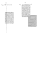
<紙指紋情報取得領域の例>
図15が、HDDに一時保管されている画像データであると仮定する。
<Example of paper fingerprint information acquisition area>
It is assumed that FIG. 15 is image data temporarily stored in the HDD.
ある領域から紙指紋情報を取得したが、そのある領域が上記画像データにより黒ベタ領域になってしまうと、照合時にマッチングの度合いが低くなる。そこで、黒ベタ領域を紙指紋取得領域として設定するのは望ましくない。 If paper fingerprint information is acquired from a certain area, but the certain area becomes a black solid area due to the image data, the degree of matching becomes low at the time of collation. Therefore, it is not desirable to set the black solid area as the paper fingerprint acquisition area.
そこで、CPU301が、上記ユーザ所望の画像データに基づいて、ドットが第1の面積割合以上打たれる領域を紙指紋情報所得禁止領域として指定する。 Therefore, the CPU 301 designates, as the paper fingerprint information income prohibited area, an area where dots are hit by the first area ratio or more based on the user-desired image data.
さらに、出力用紙の紙端に相当する領域を紙指紋情報取得禁止領域として指定する。これは、出力用紙の紙端に相当する領域は、容易に切り取られてしまうからである。紙指紋取得領域を切り取り、他の紙に貼り付けてしまうとその他の紙が紙指紋取得領域になってしまう。 Further, an area corresponding to the paper edge of the output paper is designated as a paper fingerprint information acquisition prohibited area. This is because the area corresponding to the paper edge of the output paper is easily cut out. If the paper fingerprint acquisition area is cut out and pasted on another paper, the other paper becomes the paper fingerprint acquisition area.
さらに、出力用紙を均等分割した境界線に近い領域を紙指紋取得禁止領域として指定する。これは、出力用紙が中心領域を中心としてユーザにより折り曲げられる可能性が高いからである。折り曲げられてしまうと、マッチング度合いは下がってしまい、誤判定を招くおそれがある。
以上、四つの領域を、CPU301は、を紙指紋情報取得禁止領域として指定することになる。
Furthermore, an area close to the boundary line obtained by equally dividing the output paper is designated as a paper fingerprint acquisition prohibited area. This is because the output sheet is highly likely to be bent by the user around the center area. If it is bent, the degree of matching is lowered, which may cause erroneous determination.
As described above, the CPU 301 designates the four areas as the paper fingerprint information acquisition prohibited area.
以上のように指定された領域以外の領域のうち、ドットが所定の面積割合未満打たれる領域を紙指紋情報の取得領域として決定する。 Of the areas other than the areas specified as described above, an area where dots are hit less than a predetermined area ratio is determined as an area for acquiring paper fingerprint information.
図13がHDDに一時保管されていた画像データとすると、図15に示す斜線部分と、下の黒ベタ部分とが紙指紋情報取得禁止領域として指定されることになる。そして、それ以外の部分が紙指紋情報取得領域の候補になることなる。 If FIG. 13 is the image data temporarily stored in the HDD, the hatched portion and the lower black solid portion shown in FIG. 15 are designated as the paper fingerprint information acquisition prohibited area. The other portions are candidates for the paper fingerprint information acquisition area.
なお、上記例では出力用紙を半分に折ることを想定し、用紙を均等分割した境界線に近い領域を紙指紋情報取得禁止領域として指定していたが、出力用紙の大きさに応じて紙指紋情報取得禁止領域を変更することも可能である。例えば、出力用紙がA3サイズの場合には、4つ折りを想定して紙指紋情報取得禁止領域を決定することも考えられる。 In the above example, it is assumed that the output paper is folded in half, and the area close to the boundary line obtained by equally dividing the paper is designated as the paper fingerprint information acquisition prohibited area. However, depending on the size of the output paper, It is also possible to change the information acquisition prohibited area. For example, when the output paper is A3 size, it is conceivable that the paper fingerprint information acquisition prohibited area is determined on the assumption that the output paper is folded in four.
また、用紙の種類によって、紙指紋情報取得禁止領域を決定することも可能である。例えば、厚紙の場合は通常半分に折ることが難しいため、境界線から近い領域を紙指紋情報取得禁止領域から外すことが考えられる。 It is also possible to determine the paper fingerprint information acquisition prohibited area depending on the type of paper. For example, in the case of thick paper, it is usually difficult to fold it in half.
このように、実施例1では、入力された画像データを複数の領域(1〜n)に分割し、分割後の領域を1から順番に、以下の条件を満たす領域を検索した。そして、条件を満たす領域が見つかった時点で、それを紙指紋取得領域と決定していた。 As described above, in the first embodiment, the input image data is divided into a plurality of regions (1 to n), and regions after the division are searched in order from 1 in order. Then, when a region satisfying the condition is found, it is determined as a paper fingerprint acquisition region.
以下の条件をわかりやすく記載すると、このようになる。
(条件1)紙端ではない領域か?
(条件2)境界線から遠い領域か?
(条件3)白ベタ領域ではない領域か?
(条件4)黒ベタ領域ではない領域か?
このように、条件3や条件4のように、「どの程度ドットが打たれるか」を判断する必要な重い処理を後に回し、条件1や条件2のように軽い処理を前に回すことで処理を高速化している。
It becomes like this when the following conditions are described clearly.
(Condition 1) Is the area not the edge of the paper?
(Condition 2) Is the area far from the boundary line?
(Condition 3) Is the region not a white solid region?
(Condition 4) Is it an area that is not a black solid area?
In this way, as in the condition 3 and the condition 4, the heavy processing necessary to determine “how much dots are to be hit” is deferred and the light process as in the
そして、一つでも全ての条件を満たす領域が見つかった時点で、紙指紋情報取得領域の決定処理を終了していた。 Then, when a region that satisfies all the conditions is found, the paper fingerprint information acquisition region determination process is completed.
しかしながら、全ての条件を満たす領域が後半で(例えば、n−1番目の領域やn番目の領域)しか見つからない場合には、長い処理時間がかかってしまう。 However, if a region that satisfies all the conditions is found only in the second half (for example, the (n-1) th region or the nth region), it takes a long processing time.
一方、本実施例2では、ユーザに所望の領域を選択させ、当該選択された所望の領域が上記全ての条件を満たす領域であるかを判定する。そして、判定の結果、所望の領域が上記全ての条件を満たす領域である場合には、紙指紋情報取得領域の決定処理を終了する。 On the other hand, in the second embodiment, the user is allowed to select a desired area, and it is determined whether the selected desired area is an area that satisfies all the above conditions. If the result of determination is that the desired area satisfies all the above conditions, the paper fingerprint information acquisition area determination process ends.
このように、最初からユーザに所望の領域を選択させることで、全ての条件を満たす領域が見つかるのにかかる時間を短縮することができる。
さらに、ユーザ所望の領域から紙指紋情報を取得することができる。
この実施例2における紙指紋情報取得領域決定処理のフローチャートを図18に示す。
本フローチャートにおける各工程の処理は、CPU301により統括的に制御される。
In this way, by allowing the user to select a desired region from the beginning, it is possible to reduce the time taken to find a region that satisfies all the conditions.
Furthermore, paper fingerprint information can be acquired from a user desired area.
FIG. 18 shows a flowchart of the paper fingerprint information acquisition area determination process in the second embodiment.
The processing of each process in this flowchart is comprehensively controlled by the CPU 301.
ステップ1801では、CPU301は、操作部12上の表示画面に、画像データを表示する。その上で、ユーザに対して所望の紙指紋情報取得領域を上記画像データ上から選択させるための表示を行う。この表示に対して、ユーザから所望の領域の選択があると、当該選択された領域を対象とする領域としてCPU301は、設定する。
In step 1801, the CPU 301 displays image data on the display screen on the
ステップ1802では、対象とする領域が紙端領域であるかどうかを判定する。判定の結果、対象とする領域が紙端領域でなければ、ステップ1803に移行する。対象とする領域が紙端領域であれば、ステップ1806(警告表示1)に移行する。
In
ステップ1803では、対象とする領域が、紙を均等分割した際の境界線から近い領域であるかどうかを判定する。対象とする領域が、境界線から遠い領域である場合には、ステップ1804に移行する。対象とする領域が、境界線から近い領域である場合には、ステップ1807(警告表示2)に移行する。
In
ステップ1804では、対象とする領域が、第1の所定の面積率(比較的高い面積率)以上の面積率でドットが打たれている(又は打たれる予定となっている)か、画像データに基づいて判定する。判定の結果、第1の所定の面積率より低いでドットが打たれている(又は打たれる予定となっている)となった場合には、ステップ1805に移行する。判定の結果、そうでない場合には、ステップ1808(警告表示3)に移行する。これは、黒ベタ領域を排除するための処理である。 In step 1804, whether or not the target region has dots (or is scheduled to be hit) with an area ratio equal to or higher than the first predetermined area ratio (relatively high area ratio) or image data. Determine based on. As a result of the determination, if the dot is hit (or scheduled to be hit) at a rate lower than the first predetermined area ratio, the process proceeds to step 1805. As a result of the determination, if not, the process proceeds to step 1808 (warning display 3). This is a process for eliminating the black solid area.
課題の欄にも記載したように、繊維のからまりまで読取れるのは基本的に白い画素からである。そのため、黒ベタ領域は、紙指紋情報取得領域となるのは望ましくないため、このように黒ベタ領域を排除する必要がある。 As described in the assignment section, it is basically a white pixel that can be read up to the fiber bundle. Therefore, it is not desirable that the black solid area becomes a paper fingerprint information acquisition area, and thus it is necessary to eliminate the black solid area in this way.
ステップ1805では、対象とする領域が、第2の所定の面積率(比較的低い面積率)よりも高い面積率でドットが打たれている(又は打たれる予定となっている)か、画像データに基づいて判定する。判定の結果、第2の所定の面積率より高い面積率でドットが打たれているとなった場合には、ステップ1810に移行する。そうでない場合には、ステップ1809(警告表示4)に移行する。これは、白紙領域を排除するための処理である。
In
課題の欄にも記載したように、白紙領域は切り取られ他の紙に貼り付けられやすいので、紙指紋情報取得領域となるのは望ましくないからである。
ステップ1810では、ユーザから指定された領域を適切な紙指紋領域と決定する。
S1806では、CPU301は、もっと中央に近い領域を選択して下さいというのを、ユーザに対して表示画面を通じて通知するように制御する。
S1807では、CPU301は、もっと端に近い領域を選択して下さいというのを、ユーザに対して表示画面を通じて通知するように制御する。
S1808では、CPU301は、もっと白い領域を選択して下さいというのを、ユーザに対して表示画面を通じて通知するように制御する。
S1809では、CPU301は、もっと黒い領域を選択して下さいというのを、ユーザに対して表示画面を通じて通知するように制御する。
なお、S1806〜S1809の通知に対して、ユーザが新たな領域を選択した場合には、S1801に戻る。
また、S1806〜S1809の通知に対して、「自動的に領域を選択して下さい」というのをユーザが選択した場合には、図18における処理を終了して、図14における処理に移る。つまり、実施例1に記載したフローチャートを利用する。
This is because, as described in the problem column, the blank area is easily cut out and pasted on other paper, so it is not desirable to become a paper fingerprint information acquisition area.
In step 1810, the area designated by the user is determined as an appropriate paper fingerprint area.
In step S1806, the CPU 301 controls the user to be notified through the display screen that an area closer to the center should be selected.
In step S <b> 1807, the CPU 301 controls to notify the user through the display screen that an area closer to the end should be selected.
In step S1808, the CPU 301 controls the user to be notified through the display screen that a whiter area should be selected.
In step S1809, the CPU 301 controls the user to be notified through the display screen that a blacker area should be selected.
If the user selects a new area in response to the notifications in steps S1806 to S1809, the process returns to step S1801.
If the user selects “Please select an area automatically” in response to the notifications in S1806 to S1809, the processing in FIG. 18 is terminated, and the processing in FIG. 14 is started. That is, the flowchart described in the first embodiment is used.
なお、本実施例では、S1801で自由にユーザに紙指紋情報取得領域を選択させたが、(1)かつ(2)の制限を設けてユーザに紙指紋情報取得領域を選択させてもよい。
(1)紙端領域をグレーアウトして、選択できないようにする。
(2)境界線から近い領域をグレーアウトして、選択できないようにする。
In this embodiment, the user is free to select the paper fingerprint information acquisition area in step S1801, but the user may select the paper fingerprint information acquisition area with restrictions (1) and (2).
(1) The paper edge area is grayed out so that it cannot be selected.
(2) The area close to the boundary line is grayed out so that it cannot be selected.
このようにすることで、図18のフローチャートでは、S1802,S1803の処理を行わずにすむ。そのため、処理の高速化が実現される。 By doing in this way, it is not necessary to perform the processing of S1802 and S1803 in the flowchart of FIG. As a result, the processing speed can be increased.
また、S1801で、表示画面上に、黒すぎず白すぎない領域を選択して下さいと表示するのも望ましい。 In S1801, it is also desirable to display on the display screen that an area that is neither too black nor too white is selected.
(その他の実施例)
さらに本発明は、複数の機器(例えばコンピュータ、インターフェース機器、リーダ、プリンタなど)から構成されるシステムに適用することも、一つの機器からなる装置(複合機、プリンタ、ファクシミリ装置など)に適用することも可能である。
(Other examples)
Further, the present invention can be applied to a system constituted by a plurality of devices (for example, a computer, an interface device, a reader, a printer, etc.), and can also be applied to an apparatus (multifunction device, printer, facsimile machine, etc.) comprising a single device. It is also possible.
また本発明の目的は、上述した実施例で示したフローチャートの手順を実現するプログラムコードを記憶した記憶媒体から、コンピュータがプログラムコードを読出し実行することによっても達成される。この場合、記憶媒体から読み出されたプログラムコード自体が上述した実施形態の機能を実現することになる。そのため、このプログラムコード及びプログラムコードを記憶した記憶媒体も本発明の一つを構成することになる。 The object of the present invention can also be achieved by a computer reading and executing a program code from a storage medium storing a program code for realizing the procedure of the flowchart shown in the above-described embodiment. In this case, the program code itself read from the storage medium realizes the functions of the above-described embodiment. Therefore, the program code and a storage medium storing the program code also constitute one of the present invention.
プログラムコードを供給するための記憶媒体としては、例えば、フロッピー(登録商標)ディスク、ハードディスク、光ディスク、光磁気ディスク、CD−ROM、CD−R、磁気テープ、不揮発性のメモリカード、ROMなどを用いることができる。 As a storage medium for supplying the program code, for example, a floppy (registered trademark) disk, hard disk, optical disk, magneto-optical disk, CD-ROM, CD-R, magnetic tape, nonvolatile memory card, ROM, or the like is used. be able to.
Claims (5)
前記シート上の前記特定手段で特定された領域から紙指紋情報を取得する取得手段とを有し、
前記第1の面積率は、前記第2の面積率より高く、
前記第1の面積率は黒ベタ領域に打たれているドットの面積率を示し、
前記第2の面積率は白紙領域に打たれているドットの面積率を示すことを特徴とする画像処理装置。 A specifying means for specifying a region where dots are to be printed at an area ratio lower than the first area ratio and higher than the second area ratio when the image data is printed on the sheet;
Obtaining means for obtaining paper fingerprint information from an area specified by the specifying means on the sheet;
The first area ratio is rather higher than the second area ratio,
The first area ratio indicates the area ratio of dots hitting a black solid area,
2. The image processing apparatus according to claim 1, wherein the second area ratio indicates an area ratio of dots applied to a blank area .
取得手段が、前記シート上の前記特定工程で特定された領域から紙指紋情報を取得する取得工程とを有し、
前記第1の面積率は、前記第2の面積率より高く、
前記第1の面積率は黒ベタ領域に打たれているドットの面積率を示し、
前記第2の面積率は白紙領域に打たれているドットの面積率を示すことを特徴とする画像処理装置の制御方法。 A specifying step of specifying a region in which dots are hit with an area ratio lower than the first area ratio and higher than the second area ratio when the image data is printed on the sheet;
An acquisition unit having an acquisition step of acquiring paper fingerprint information from an area specified in the specific step on the sheet;
The first area ratio is rather higher than the second area ratio,
The first area ratio indicates the area ratio of dots hitting a black solid area,
The method of controlling an image processing apparatus according to claim 2, wherein the second area ratio indicates an area ratio of dots applied to a blank area .
Priority Applications (3)
| Application Number | Priority Date | Filing Date | Title |
|---|---|---|---|
| JP2006203373A JP4709090B2 (en) | 2006-07-26 | 2006-07-26 | Image processing apparatus, image processing apparatus control method, and program |
| US11/778,370 US8077342B2 (en) | 2006-07-26 | 2007-07-16 | Image processing apparatus, method of controlling image processing apparatus, program, and storage medium |
| CNB200710129780XA CN100559825C (en) | 2006-07-26 | 2007-07-26 | The method of image processing apparatus and control image processing apparatus |
Applications Claiming Priority (1)
| Application Number | Priority Date | Filing Date | Title |
|---|---|---|---|
| JP2006203373A JP4709090B2 (en) | 2006-07-26 | 2006-07-26 | Image processing apparatus, image processing apparatus control method, and program |
Publications (3)
| Publication Number | Publication Date |
|---|---|
| JP2008034944A JP2008034944A (en) | 2008-02-14 |
| JP2008034944A5 JP2008034944A5 (en) | 2009-10-08 |
| JP4709090B2 true JP4709090B2 (en) | 2011-06-22 |
Family
ID=38986386
Family Applications (1)
| Application Number | Title | Priority Date | Filing Date |
|---|---|---|---|
| JP2006203373A Expired - Fee Related JP4709090B2 (en) | 2006-07-26 | 2006-07-26 | Image processing apparatus, image processing apparatus control method, and program |
Country Status (3)
| Country | Link |
|---|---|
| US (1) | US8077342B2 (en) |
| JP (1) | JP4709090B2 (en) |
| CN (1) | CN100559825C (en) |
Families Citing this family (6)
| Publication number | Priority date | Publication date | Assignee | Title |
|---|---|---|---|---|
| EP1739947B1 (en) * | 2005-06-30 | 2013-10-02 | Canon Kabushiki Kaisha | Density determination method, image forming apparatus, and image processing system |
| EP2126841A2 (en) * | 2007-01-16 | 2009-12-02 | Optasia Medical, Limited | Image processing systems and methods |
| JP4362613B2 (en) * | 2007-07-20 | 2009-11-11 | シャープ株式会社 | Scanner device and information display system including the scanner device |
| US7957173B2 (en) | 2008-10-14 | 2011-06-07 | Mosaid Technologies Incorporated | Composite memory having a bridging device for connecting discrete memory devices to a system |
| US8549209B2 (en) * | 2008-11-04 | 2013-10-01 | Mosaid Technologies Incorporated | Bridging device having a configurable virtual page size |
| US11715314B2 (en) * | 2020-07-07 | 2023-08-01 | Xerox Corporation | Performance improvement with object detection for software based image path |
Citations (4)
| Publication number | Priority date | Publication date | Assignee | Title |
|---|---|---|---|---|
| JP2001103288A (en) * | 1999-09-30 | 2001-04-13 | Canon Inc | Image processing device and image processing method |
| JP2001103299A (en) * | 1999-09-30 | 2001-04-13 | Canon Inc | Image processing device and image processing method |
| JP2005038389A (en) * | 2003-06-24 | 2005-02-10 | Fuji Xerox Co Ltd | Method, apparatus and program for authenticity determination |
| JP2006164180A (en) * | 2004-12-10 | 2006-06-22 | Fuji Xerox Co Ltd | Solid identification apparatus and method |
Family Cites Families (12)
| Publication number | Priority date | Publication date | Assignee | Title |
|---|---|---|---|---|
| JPH11331626A (en) * | 1998-03-09 | 1999-11-30 | Minolta Co Ltd | Image processor |
| US7372594B1 (en) * | 1999-09-30 | 2008-05-13 | Canon Kabushiki Kaisha | Image processing apparatus and method, and storage medium |
| JP2004042371A (en) * | 2002-07-10 | 2004-02-12 | Canon Inc | Method and program for determining recording medium, recording medium and recorder |
| JP3919618B2 (en) * | 2002-07-10 | 2007-05-30 | キヤノン株式会社 | Recording medium discrimination method, program, storage medium, and recording apparatus |
| JP2004112644A (en) | 2002-09-20 | 2004-04-08 | Fuji Xerox Co Ltd | Original-registering device, original-confirming device, and mark for collating original |
| WO2007012816A1 (en) * | 2005-07-27 | 2007-02-01 | Ingenia Technology Limited | Verification of authenticity |
| US7809156B2 (en) * | 2005-08-12 | 2010-10-05 | Ricoh Company, Ltd. | Techniques for generating and using a fingerprint for an article |
| US7731435B2 (en) * | 2005-08-12 | 2010-06-08 | Ricoh Company, Ltd. | Techniques for printing with integrated paper sheet identification |
| GB2429950B (en) * | 2005-09-08 | 2007-08-22 | Ingenia Holdings | Copying |
| JP4836260B2 (en) * | 2006-12-05 | 2011-12-14 | キヤノン株式会社 | Image forming apparatus, image forming method, recording medium, and program |
| JP4812106B2 (en) * | 2006-12-05 | 2011-11-09 | キヤノン株式会社 | Image reading apparatus and control method thereof |
| US7865124B2 (en) * | 2007-03-30 | 2011-01-04 | Ricoh Company, Ltd. | Pre-scanning printer with paper fingerprinting |
-
2006
- 2006-07-26 JP JP2006203373A patent/JP4709090B2/en not_active Expired - Fee Related
-
2007
- 2007-07-16 US US11/778,370 patent/US8077342B2/en not_active Expired - Fee Related
- 2007-07-26 CN CNB200710129780XA patent/CN100559825C/en not_active Expired - Fee Related
Patent Citations (4)
| Publication number | Priority date | Publication date | Assignee | Title |
|---|---|---|---|---|
| JP2001103288A (en) * | 1999-09-30 | 2001-04-13 | Canon Inc | Image processing device and image processing method |
| JP2001103299A (en) * | 1999-09-30 | 2001-04-13 | Canon Inc | Image processing device and image processing method |
| JP2005038389A (en) * | 2003-06-24 | 2005-02-10 | Fuji Xerox Co Ltd | Method, apparatus and program for authenticity determination |
| JP2006164180A (en) * | 2004-12-10 | 2006-06-22 | Fuji Xerox Co Ltd | Solid identification apparatus and method |
Also Published As
| Publication number | Publication date |
|---|---|
| JP2008034944A (en) | 2008-02-14 |
| CN100559825C (en) | 2009-11-11 |
| US8077342B2 (en) | 2011-12-13 |
| CN101115125A (en) | 2008-01-30 |
| US20080025637A1 (en) | 2008-01-31 |
Similar Documents
| Publication | Publication Date | Title |
|---|---|---|
| JP4810413B2 (en) | Image processing apparatus and image processing method | |
| JP4732315B2 (en) | Image processing apparatus and method | |
| US8019113B2 (en) | Image processing apparatus, control method therefore, program, and storage medium | |
| US8184344B2 (en) | Image processing apparatus and image processing method, computer program and storage medium | |
| JP4732314B2 (en) | Image processing apparatus and image processing method | |
| US8040571B2 (en) | Image processing for extracting unique information from region of paper determined to be suitable | |
| JP4812106B2 (en) | Image reading apparatus and control method thereof | |
| JP4709090B2 (en) | Image processing apparatus, image processing apparatus control method, and program | |
| US8345980B2 (en) | Image processing apparatus, image processing method, and computer-readable storage medium to determine whether a manuscript is an original by using paper fingerprint information | |
| JP2009005091A (en) | Image forming apparatus, control method of the same, program and storage medium | |
| JP2008283586A (en) | Image processor, control method of image processor, program and storage medium | |
| JP4267029B2 (en) | Image processing apparatus, image processing method, image processing method program, and storage medium therefor | |
| US8059296B2 (en) | Image forming apparatus that synthesizes fiber information extracted from pages of a paper medium having a plurality of pages, and an image forming apparatus control method, a program, and a storage medium relating thereto | |
| JP2008141683A (en) | Image processor, method and program, and storage medium | |
| JP2010050551A (en) | Image formation device | |
| JP4906488B2 (en) | Image forming apparatus, image forming method, and program | |
| JP2012039629A (en) | Apparatus for decoding two-dimensional code, control method of apparatus for decoding two-dimensional code, and program | |
| JP4498375B2 (en) | OUTPUT DEVICE, OUTPUT METHOD, OUTPUT SYSTEM, AND PROGRAM | |
| JP2008066840A (en) | Image processor, image processing method, program of image processing method and its storage medium | |
| JP2010056912A (en) | Image processing apparatus | |
| JP2010239204A (en) | Image processor, image processing method, program, and storage medium | |
| JP2008310027A (en) | Image forming apparatus, image forming method, recording medium and program | |
| JP2008244611A (en) | Image processing unit and image processing method | |
| JP2008079005A (en) | Copy system, and program | |
| JP2009141493A (en) | Image processing apparatus, image processing method, program and storage medium |
Legal Events
| Date | Code | Title | Description |
|---|---|---|---|
| A621 | Written request for application examination |
Free format text: JAPANESE INTERMEDIATE CODE: A621 Effective date: 20090727 |
|
| A521 | Request for written amendment filed |
Free format text: JAPANESE INTERMEDIATE CODE: A523 Effective date: 20090825 |
|
| RD04 | Notification of resignation of power of attorney |
Free format text: JAPANESE INTERMEDIATE CODE: A7424 Effective date: 20100201 |
|
| RD01 | Notification of change of attorney |
Free format text: JAPANESE INTERMEDIATE CODE: A7421 Effective date: 20100630 |
|
| A977 | Report on retrieval |
Free format text: JAPANESE INTERMEDIATE CODE: A971007 Effective date: 20100722 |
|
| A131 | Notification of reasons for refusal |
Free format text: JAPANESE INTERMEDIATE CODE: A131 Effective date: 20100803 |
|
| A521 | Request for written amendment filed |
Free format text: JAPANESE INTERMEDIATE CODE: A523 Effective date: 20100908 |
|
| A01 | Written decision to grant a patent or to grant a registration (utility model) |
Free format text: JAPANESE INTERMEDIATE CODE: A01 Effective date: 20110315 |
|
| A61 | First payment of annual fees (during grant procedure) |
Free format text: JAPANESE INTERMEDIATE CODE: A61 Effective date: 20110317 |
|
| LAPS | Cancellation because of no payment of annual fees |