JP2009042132A - Apparatus and method for map display - Google Patents
Apparatus and method for map display Download PDFInfo
- Publication number
- JP2009042132A JP2009042132A JP2007208968A JP2007208968A JP2009042132A JP 2009042132 A JP2009042132 A JP 2009042132A JP 2007208968 A JP2007208968 A JP 2007208968A JP 2007208968 A JP2007208968 A JP 2007208968A JP 2009042132 A JP2009042132 A JP 2009042132A
- Authority
- JP
- Japan
- Prior art keywords
- current position
- map
- display device
- map display
- route
- Prior art date
- Legal status (The legal status is an assumption and is not a legal conclusion. Google has not performed a legal analysis and makes no representation as to the accuracy of the status listed.)
- Granted
Links
- 238000000034 method Methods 0.000 title claims description 33
- 238000012937 correction Methods 0.000 claims abstract description 107
- 238000004891 communication Methods 0.000 claims description 19
- 238000004590 computer program Methods 0.000 claims description 5
- 238000001514 detection method Methods 0.000 claims 1
- 230000001413 cellular effect Effects 0.000 abstract 5
- 230000008569 process Effects 0.000 description 26
- 238000012986 modification Methods 0.000 description 8
- 230000004048 modification Effects 0.000 description 8
- 238000012545 processing Methods 0.000 description 7
- 238000005259 measurement Methods 0.000 description 5
- 238000010586 diagram Methods 0.000 description 4
- 230000006870 function Effects 0.000 description 4
- 239000004973 liquid crystal related substance Substances 0.000 description 4
- 230000004044 response Effects 0.000 description 3
- 229920001690 polydopamine Polymers 0.000 description 2
- 230000001133 acceleration Effects 0.000 description 1
- 230000008859 change Effects 0.000 description 1
- 238000006243 chemical reaction Methods 0.000 description 1
- 238000005516 engineering process Methods 0.000 description 1
- 238000004519 manufacturing process Methods 0.000 description 1
- 238000012876 topography Methods 0.000 description 1
Images


Abstract
Description
本発明は、GPS等によって測位した現在位置を補正する技術に関する。 The present invention relates to a technique for correcting a current position measured by GPS or the like.
近年、GPS(Global Positioning System/全地球測位システム)を用いて現在位置を測位し、その位置を地図上に表示する地図表示装置が普及している。GPSを用いた測位技術では、衛星からの電波の受信状況や捕捉した衛星の数に応じて、数メートルないし数十メートルの誤差が生じてしまうことが知られている。そのため、従来の地図表示装置では、測位した現在位置に誤差が生じていた場合に、近隣の道路や経路上の位置に現在位置を強制的に補正することが行われていた(下記、特許文献1参照)。 In recent years, map display devices that measure the current position using GPS (Global Positioning System) and display the position on a map have become widespread. In positioning technology using GPS, it is known that an error of several meters to several tens of meters occurs depending on the reception status of radio waves from satellites and the number of captured satellites. Therefore, in the conventional map display device, when there is an error in the current position measured, the current position is forcibly corrected to a position on a nearby road or route (the following patent document). 1).
従来の地図表示装置は、車両に搭載されることを前提として設計されていることが多く、補正が行われる範囲も、車両の移動特性に合わせて設定されていた。例えば、特許文献1には、案内ルートから左右200m以内の範囲に現在位置が測位されれば、案内ルート上に現在位置を補正すると記載されている。 Conventional map display devices are often designed on the assumption that they are mounted on a vehicle, and the range in which correction is performed is also set in accordance with the movement characteristics of the vehicle. For example, Patent Document 1 describes that if the current position is measured within a range of 200 m to the left or right of the guide route, the current position is corrected on the guide route.
しかし、近年、GPSの受信機は、携帯電話やPDA等の小型機器にも搭載されつつある。こうした小型機器は、車両内だけではなく、歩行時や自転車による移動等にも利用することが可能である。そのため、従来の現在位置の補正方法では、利用者の多様な移動手段に対応することが困難になってきている。 However, in recent years, GPS receivers are being installed in small devices such as mobile phones and PDAs. Such a small device can be used not only in a vehicle but also for walking or traveling by bicycle. Therefore, it is becoming difficult for the conventional current position correction method to cope with various moving means of the user.
このような問題を考慮し、本発明が解決しようとする課題は、現在位置を地図上に表示する装置において、現在位置の補正を利用者の移動手段に応じて行うことにある。 In consideration of such problems, the problem to be solved by the present invention is to perform correction of the current position in accordance with the moving means of the user in an apparatus that displays the current position on a map.
上記課題を踏まえ、本発明の一態様である地図表示装置を次のように構成した。 Based on the above problems, a map display device according to an aspect of the present invention is configured as follows.
本発明の一態様である地図表示装置は、
現在位置を地図上に表示する地図表示装置であって、
進行すべき経路を示す情報を含む地図データを取得するデータ取得部と、
利用者の移動手段の種別を判別する移動手段判別部と、
現在位置を逐次検出する位置検出部と、
前記検出された現在位置を前記経路上の位置に補正する範囲である補正領域を、前記判別された移動手段の種別に応じて設定する補正領域設定部と、
前記現在位置が、前記設定された補正領域内に検出された場合に限り、該現在位置を前記経路上の位置に補正する補正部と、
前記補正された現在位置を前記地図データによって表される地図画像上に表示する表示部とを備える。
A map display device according to one aspect of the present invention is provided.
A map display device that displays a current position on a map,
A data acquisition unit for acquiring map data including information indicating a route to be traveled;
A moving means discriminating unit for discriminating the type of moving means of the user;
A position detector that sequentially detects the current position;
A correction area setting unit that sets a correction area that is a range for correcting the detected current position to a position on the route according to the type of the determined moving means;
A correction unit that corrects the current position to a position on the path only when the current position is detected within the set correction area;
A display unit that displays the corrected current position on a map image represented by the map data.
上記態様の地図表示装置によれば、現在位置の補正を行うか否かを決定するための補正領域の範囲が、利用者の移動手段の種別に応じて設定される。従って、現在位置に測定誤差が生じた場合に、利用者の移動手段に応じた好ましい補正を行うことが可能になる。なお、表示部が画面に表示する地図画像は、ラスタ形式で表されていてもよいし、ベクトル形式で表されていてもよい。 According to the map display device of the above aspect, the range of the correction area for determining whether or not to correct the current position is set according to the type of moving means of the user. Therefore, when a measurement error occurs at the current position, it is possible to perform a preferable correction according to the moving means of the user. Note that the map image displayed on the screen by the display unit may be represented in a raster format or a vector format.
上記態様の地図表示装置において、前記補正領域設定部は、前記補正領域として、前記経路を中心として、左右方向に、前記移動手段の種別に応じて定められた距離だけ広がりを有する領域を設定することができる。こうすることで、経路を中心とした左右方向の補正領域の範囲を移動手段の種別に応じて可変させることが可能になる。 In the map display device according to the aspect described above, the correction area setting unit sets, as the correction area, an area having a spread by a distance determined according to the type of the moving unit in the left-right direction with the route as a center. be able to. This makes it possible to vary the range of the correction area in the left-right direction centered on the route according to the type of the moving means.
上記態様の地図表示装置において、前記補正領域設定部は、前記移動手段が車両である場合に、前記補正領域として、前回補正された現在位置を後端とし、該後端から前記移動手段の種別に応じた定められた距離だけ前方に先端がある領域を設定することができる。 In the map display device according to the aspect described above, when the moving unit is a vehicle, the correction area setting unit sets, as the correction area, the current position corrected last time as the rear end, and the type of the moving unit from the rear end. It is possible to set a region having a tip in front by a predetermined distance according to.
車両が経路上を進行している場合にはバックをすることはほとんどないと考えられる。そのため、かかる態様のように、前回補正された現在位置を後端とする補正領域を設定すれば、前回検出された現在位置よりも後ろ側に現在位置が検出された場合に、現在位置を補正することが不要となる。この結果、表示される地図画像にブレが生じることを抑制することが可能になる。また、上記態様によれば、補正領域の経路に沿った長さが移動手段に応じて設定されるので、移動手段の速度に応じて、現在位置の補正を行う範囲を可変させることが可能になる。 When the vehicle is traveling on the route, it is considered that there is almost no back. Therefore, if a correction area with the current position corrected last time as the rear end is set as in this mode, the current position is corrected when the current position is detected behind the current position detected last time. It becomes unnecessary to do. As a result, it is possible to suppress blurring in the displayed map image. Further, according to the above aspect, since the length along the path of the correction area is set according to the moving unit, it is possible to vary the range for correcting the current position according to the speed of the moving unit. Become.
上記態様の地図表示装置において、前記補正領域設定部は、前記移動手段が徒歩である場合に、前記補正領域として、前回補正された現在位置から所定の距離だけ前方および後方に広がりを有する領域を設定することができる。 In the map display device according to the aspect described above, when the moving unit is walking, the correction area setting unit includes, as the correction area, an area that extends forward and backward by a predetermined distance from the current position corrected last time. Can be set.
移動手段が徒歩の場合には、歩行者は、経路上を前進するだけでなく、左右に逸れたり、逆向きに進行する可能性がある。そのため、かかる態様のように、前回補正された現在位置から後方にも補正領域を設けることで、歩行者の移動特性を考慮した補正を行うことが可能になる。なお、前回補正された現在位置から前方への距離と後方への距離は、同一である必要はない。 When the moving means is walking, the pedestrian may not only move forward on the route but also deviate left and right or move in the opposite direction. Therefore, by providing a correction area behind the current position corrected last time as in this aspect, it is possible to perform correction in consideration of the pedestrian's movement characteristics. It should be noted that the forward distance and the backward distance from the current position corrected last time do not have to be the same.
上記態様の地図表示装置において、前記補正領域の先端は、前記経路上に頂点を有する三角形状に形成されてもよい。こうすることで、検出された現在位置が、前回補正された現在位置から前方に離れるほど測定誤差を許容する範囲を狭めることができる。この結果、精度の高い補正を行うことが可能になる。 In the map display device according to the aspect described above, the tip of the correction area may be formed in a triangular shape having a vertex on the route. By doing so, the range in which the measurement error is allowed can be narrowed as the detected current position moves further forward from the previously corrected current position. As a result, highly accurate correction can be performed.
上記態様の地図表示装置において、前記補正領域設定部は、前記判別された移動手段と、前記経路の属性とに応じて前記補正領域を設定してもよい。経路の属性とは、例えば、一般道や高速道路といった道路の種別のことをいう。このような態様であれば、移動手段の種別だけではなく、経路の制限速度等の特性に応じて、補正領域を設定することが可能になる。 In the map display device according to the aspect described above, the correction area setting unit may set the correction area according to the determined moving means and the attribute of the route. The attribute of the route refers to a road type such as a general road or a highway. With such an aspect, it becomes possible to set the correction area according to characteristics such as the speed limit of the route as well as the type of moving means.
上記態様の地図表示装置において、前記移動手段判別部は、前記逐次検出された現在位置の履歴に基づき、前記移動手段の種別を判別してもよい。このような態様であれば、動的に補正領域の範囲を設定することが可能になるので、ユーザは、移動手段を乗り換える度に、設定の変更を行う必要がなくなり、利便性が向上することになる。 In the map display device according to the aspect described above, the moving means determination unit may determine the type of the moving means based on the sequentially detected current position history. In such an aspect, the range of the correction area can be set dynamically, so that the user does not need to change the setting each time the moving means is changed, and convenience is improved. become.
上記態様の地図表示装置において、前記補正領域設定部は、前記判別された移動手段の速度に応じて、前記補正領域を調整することができる。こうすることで、移動手段の種別だけではなく、その速度に応じて、動的に補正領域を調整することが可能になる。 In the map display device of the above aspect, the correction area setting unit can adjust the correction area according to the determined speed of the moving means. By doing so, it becomes possible to dynamically adjust the correction area according to not only the type of moving means but also its speed.
上記態様の地図表示装置は、更に、前記補正領域よりも外側の領域であり、前記進行すべき経路と異なる経路を取得するかを判断するためのリルート領域を、前記判別された移動手段に応じて設定するリルート領域設定部と、前記現在位置が、前記設定されたリルート領域内に検出された場合に、前記経路と異なる経路であって、該現在位置を出発地とする新たな経路を取得するリルート部とを備えてもよい。 The map display device according to the aspect further includes a reroute area that is an area outside the correction area and for determining whether to acquire a route different from the route to be traveled according to the determined moving means. When the reroute area setting unit to be set and the current position are detected within the set reroute area, a new route that is different from the route and starts from the current position is acquired. And a reroute unit that performs the above operation.
このような態様であれば、現在位置が、現在の経路を大きく外れ、リルート領域に検出された場合に、その現在位置を出発地とする新たな経路を取得することができる。リルート領域についても、移動手段の種別に応じて設定されるので、ユーザの利便性を更に高めることができる。 According to such an aspect, when the current position greatly deviates from the current route and is detected in the reroute area, a new route starting from the current position can be acquired. Since the reroute area is also set according to the type of moving means, the convenience for the user can be further enhanced.
上記態様の地図表示装置において、前記表示部は、前記現在位置が、前記補正領域よりも外側にあり、かつ、前記リルート領域よりも内側にある不感領域に検出された場合に、前記検出された現在位置をそのまま前記地図画像上に表示してもよい。 In the map display device according to the aspect described above, the display unit detects the current position when the current position is detected in a dead area outside the correction area and inside the reroute area. The current position may be displayed on the map image as it is.
このような態様であれば、現在位置が補正領域外に検出されたとしても、直ちに新たな経路が取得されることがない。そのため、地図表示のレスポンスが低下してしまうことを抑制することが可能になる。また、このような態様であれば、不感領域に現在位置が検出された場合に、ユーザに、経路を外れていることを示唆することができるので、ユーザは、新たな経路の取得を待つことなくスムーズに経路に復帰することが可能になる。 In this manner, even if the current position is detected outside the correction area, a new route is not immediately acquired. Therefore, it becomes possible to suppress that the response of a map display falls. Further, in such a mode, when the current position is detected in the insensitive area, it can be suggested to the user that the route is off, so the user waits for acquisition of a new route. It is possible to return to the route smoothly without any problems.
上記態様の地図表示装置において、前記データ取得部は、前記地図データを、無線通信によって所定のサーバから取得することができる。このような態様であれば、地図表示装置自体に、地図データを記憶するための記憶装置を備えておく必要がないため、装置のコンパクト化や製造コストの削減を図ることが可能になる。また、地図データを所定のサーバに蓄えておくことにより、地図データの更新を容易に行うことが可能になる。 In the map display device according to the above aspect, the data acquisition unit can acquire the map data from a predetermined server by wireless communication. According to such an aspect, it is not necessary to provide the map display device itself with a storage device for storing the map data, so that the device can be made compact and the manufacturing cost can be reduced. Further, by storing the map data in a predetermined server, the map data can be easily updated.
なお、本発明は、上述した地図表示装置としての構成のほか、地図表示方法や、コンピュータプログラムとしても構成することができる。かかるコンピュータプログラムは、コンピュータが読取可能な記録媒体に記録されていてもよい。記録媒体としては、例えば、フレキシブルディスクやCD−ROM、DVD−ROM、光磁気ディスク、メモリカード、ハードディスク等の種々の媒体を利用することができる。 In addition to the configuration as the map display device described above, the present invention can also be configured as a map display method or a computer program. Such a computer program may be recorded on a computer-readable recording medium. As the recording medium, for example, various media such as a flexible disk, a CD-ROM, a DVD-ROM, a magneto-optical disk, a memory card, and a hard disk can be used.
以下、本発明の実施の形態を実施例に基づき次の順序で説明する。
A.地図表示システムの概略構成:
B.経路探索処理:
C.地図表示処理:
D.変形例:
Hereinafter, embodiments of the present invention will be described in the following order based on examples.
A. Schematic configuration of map display system:
B. Route search process:
C. Map display processing:
D. Variations:
A.地図表示システムの概略構成:
図1は、本発明の実施例としての地図表示システム10の概略構成を示す説明図である。図示するように、本実施例の地図表示システム10は、経路探索サーバ100と、地図サーバ150と、地図表示装置としての携帯電話200とを含んでいる。本実施例の携帯電話200は、GPS受信機201を備えており、これを用いて経路案内を行う機能を備えている。携帯電話200は、人が携帯する場合には歩行者用ナビゲーション装置として機能し、車両で用いる場合には、カーナビゲーション装置として機能する。
A. Schematic configuration of map display system:
FIG. 1 is an explanatory diagram showing a schematic configuration of a
携帯電話200は、GPS受信機201と、表示パネル202と、音声出力部203と、無線通信回路205と、コマンド入力部206と、主制御部210と、通話制御部220とを備えている。
The
主制御部210は、携帯電話200の各部を制御するためのコントローラである。主制御部210は、CPU211と、RAM212と、ROM213とを備えている。CPU211は、ROM213に記憶された制御プログラムをRAM212にロードして実行することで、後述する種々の処理を実現する。主制御部210は、本願の「移動手段判別部」や「補正領域設定部」、「補正部」等に相当する。
The main control unit 210 is a controller for controlling each unit of the
GPS受信機201は、GPS(Global Positioning System/全地球測位システム)を構成する人工衛星から送信された電波を受信する装置である。主制御部210は、GPS受信機201が受信した電波に基づき現在位置を検出(測位)する。主制御部210は、GPS受信機201が、3つの衛星から電波を受信することができれば、2次元的な現在位置を検出することができ、4つの衛星から電波を受信することができれば、3次元的な現在位置を検出することができる。また、5つ以上の衛星から電波を受信することができれば、高精度に現在位置を検出することができる。
The
表示パネル202は、液晶ディスプレイとこれを駆動する駆動回路とを備えている。液晶ディスプレイは、たとえば、480画素×640画素(VGA)の解像度を有する。主制御部210は、表示パネル202を制御することで、地図画像や推奨経路、現在位置などを表示する。表示パネル202には、液晶ディスプレイに限らず、有機ELディスプレイなど、種々の表示装置を採用することが可能である。
The
音声出力部203は、経路案内時に音声を出力するためのスピーカや、これを駆動する回路などから構成される。
The
無線通信回路205は、基地局BSとの間でデータ通信もしくは音声通信を行うための回路である。基地局BSには、インターネットINTを介して経路探索サーバ100や地図サーバ150が接続されている。無線通信回路205は、基地局BSを介して、経路探索サーバ100や地図サーバ150にアクセスを行うことができる。
The
通話制御部220は、音声通話のための着信や呼出、音声信号と電気信号の変換などを行う回路である。
The
コマンド入力部206は、テンキー206aやカーソルキー206bなどのボタン群から構成される。ユーザは、これらのボタンを用いることで、経路探索に用いられる出発地や目的地などの入力を行うことができる。
The
地図サーバ150は、通信部152と、制御部154と、記憶装置155とを備えている。記憶装置155は、地図データベース156を記憶している。通信部152は、インターネットINTを介して携帯電話200と通信を行うことができる。地図データベース156には、携帯電話200に供給する地図データがベクトル形式で記録されている。この地図データには、地形や建物、道路等の形状を表すデータが含まれている。制御部154は、携帯電話200から地図データの取得要求があると、指定された範囲の地図データを地図データベース156から検索し、通信部152を介して携帯電話200に送信する。
The
経路探索サーバ100は、通信部102と、制御部104と、記憶装置105とを備えている。通信部102は、インターネットINTを介して携帯電話200と通信を行うことができる。記憶装置105には、道路のつながり状態や道路の属性が記録された経路データベース106が記憶されている。道路のつながり状態は、交差点や分岐点等の緯度経度からなるノードデータと、ノードデータを結ぶ線分によって道路を表すリンクデータとによって表されている。経路探索サーバ100は、携帯電話200から経路探索要求があると、経路データベース106を用いて、指定された出発地と目的地とを結ぶ推奨経路を探索する。そして、探索の結果、得られた推奨経路データを通信部102を介して携帯電話200に送信する。
The
本実施例では、経路探索サーバ100の制御部104は、自己の記憶装置105に記憶された経路データベース106を用いて経路探索を行うものとする。しかし、経路データベース106が地図サーバ150に記憶されている場合には、インターネットINT経由で、この経路データベース106を読み込んで利用してもよい。なお、経路探索サーバ100と地図サーバ150は、一体のサーバとして構成することも可能である。地図サーバ150から携帯電話200に送信される地図データと、経路探索サーバから携帯電話200に送信される推奨経路データとは、併せて、広義の「地図データ」として捉えることが可能である。
In the present embodiment, the
B.経路探索処理:
図2は、携帯電話200の主制御部210が実行する経路探索処理のフローチャートである。この処理は、ユーザが、コマンド入力部206を用いて、携帯電話200の経路案内機能を呼び出した場合に実行される処理である。
B. Route search process:
FIG. 2 is a flowchart of route search processing executed by the main control unit 210 of the
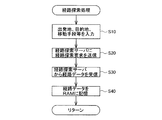
経路探索処理が開始されると、まず、主制御部210は、コマンド入力部206を介して、ユーザから、必要に応じて、出発地、目的地、経由地、探索条件、利用する移動手段の種別等の入力を受け付ける(ステップS10)。出発地は、GPS受信機201によって検出した現在位置とすることが可能である。探索条件とは、VICS(Vehicle Information and Communication System)情報の使用の要否、出発時間や到着時間の指定、階段や屋根のある歩道を用いるか否か等の条件である。利用する移動手段は、例えば、表示パネル202に表示される「徒歩」、「自転車」、「自動車」、「電車」等の選択肢の中から、所定のGUI(グラフィカルユーザインタフェース)によって選択的に入力することができる。これらの入力を受け付けると、主制御部210は、無線通信回路205を用いて、経路探索サーバ100に、経路探索の要求信号を送信する(ステップS20)。この要求信号には、ステップS10で入力された情報が含まれている。
When the route search process is started, first, the main control unit 210 receives a command from the user via the
経路探索サーバ100は、携帯電話200から経路探索の要求信号を受信すると、記憶部105に記憶された経路データベース106を参照して、要求信号に含まれる出発地と目的地とを結び(経由地が設定されていれば経由地を含む)、設定された探索条件を満たす推奨経路を算出する。推奨経路の算出は、例えば、周知のダイクストラ法を用いて行うことができる。経路探索サーバ100は、推奨経路を算出すると、その経路の形状を表すデータを、推奨経路データとしてベクトル形式で携帯電話200に返信する。推奨経路データには、その経路を構成する道路毎に属性情報として、その道路の種別を表す情報が記録されている。道路の種別には、例えば、一般道や高速道路といった種別が含まれている。なお、経路データベース106が移動手段毎に用意されている場合には、経路探索サーバ100は、ユーザが入力した移動手段に対応する経路データベースを用いて推奨経路を求める。こうすることで、ユーザの移動手段に適した経路を案内することができる。また、ユーザから移動手段の種別が入力されなかった場合には、デフォルトの移動手段(例えば、車両)に適した推奨経路を求めるものとしてもよい。また、出発地と目的地との距離に応じて移動手段を自動的に選択し、その移動手段に適した推奨経路を求めるものとしてもよい。例えば、出発地と目的地との距離が500m以内であれば徒歩、500m〜2kmであれば、徒歩及び車両、それ以上であれば車両、500km以上であれば、車両、電車、航空機や船舶を含む経路を探索するものとすることができる。もちろん、ユーザは、自分で移動手段を任意に選択することが可能である。
When the
携帯電話200の主制御部210は、経路探索サーバ100から推奨経路データを受信すると(ステップS30)、その推奨経路データをRAM212に記憶する(ステップS40)。RAM212に記憶された推奨経路データは、後述する地図表示処理において、表示パネル202上に表示される。
When receiving the recommended route data from the route search server 100 (step S30), the main control unit 210 of the
C.地図表示処理:
図3は、図2に示した経路探索処理に引き続いて実行される地図表示処理のフローチャートである。本実施例では、携帯電話200の主制御部210は、この処理を、1秒に1回実行するものとする。なお、実行のタイミングは、ユーザの移動手段や移動速度に応じて変更することとしてもよい。例えば、移動手段が車両であれば、1秒間に数回実行し、徒歩であれば、数秒に1回程度実行することとすることができる。
C. Map display processing:
FIG. 3 is a flowchart of the map display process executed subsequent to the route search process shown in FIG. In the present embodiment, it is assumed that the main control unit 210 of the
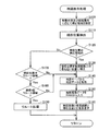
この地図表示処理が実行されると、まず、主制御部210は、ユーザの移動手段と、現在通行中の道路の属性に応じて、補正領域DAの範囲を設定する(ステップS100)。補正領域DAとは、後述するステップS110で検出した現在位置を、推奨経路上の位置に補正するか否かを決定するための領域である。現在通行中の道路の属性は、RAM212に記憶された推奨経路データを参照することで認識することができる。
When the map display process is executed, first, the main control unit 210 sets the range of the correction area DA according to the user's moving means and the attribute of the currently passing road (step S100). The correction area DA is an area for determining whether or not to correct the current position detected in step S110 described later to a position on the recommended route. The attribute of the road currently being traveled can be recognized by referring to the recommended route data stored in the
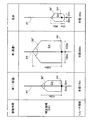
図4は、移動手段に応じた補正領域DAを例示する説明図である。図4には、移動手段が車で一般道を通行している場合の補正領域DAと、同じく移動手段が車で高速道路を通行している場合の補正領域DAと、移動手段が徒歩の場合の補正領域DAを示している。図示するように、補正領域DAは、速度の速い移動手段ほど、その面積が大きく設定される。 FIG. 4 is an explanatory diagram illustrating the correction area DA corresponding to the moving means. FIG. 4 shows a correction area DA when the moving means is traveling on a general road by car, a correction area DA when the moving means is traveling by car on the highway, and a case where the moving means is walking. The correction area DA is shown. As shown in the drawing, the correction area DA is set to have a larger area as the moving means has a higher speed.
例えば、移動手段が車で一般道を通行している場合には、補正領域DAは、当該地図表示処理を前回実行した結果、補正された現在位置PPから、推奨経路RTを挟んで左右方向にそれぞれ50m、推奨経路RTに沿って前方に150mの範囲を有する領域であり、先端部が80°の角度を有する三角形状に形成された領域に設定される。この先端部の頂点は、推奨経路RT上に位置している。 For example, when the moving means is traveling on a general road by car, the correction area DA is moved in the horizontal direction across the recommended route RT from the corrected current position PP as a result of the previous execution of the map display process. Each of the regions has a range of 50 m and a length of 150 m forward along the recommended route RT, and the tip portion is set to a region formed in a triangular shape having an angle of 80 °. The apex of the tip is located on the recommended route RT.
移動手段が車で高速道路を通行している場合には、補正領域DAは、前回の現在位置PPから推奨経路RTを挟んで左右方向にそれぞれ100m、推奨経路RTに沿って前方に250mの領域を有し、先端部が120°の角度を有する三角形状に形成された領域に設定される。一般道を通行している場合に比べ、補正領域DAが前方向に長いのは、一般道よりも高速道路の方が移動速度が速いためであり、左右方向の広がりが大きいのは、高速道路では、経路を逸れて移動することが困難であることから、測定誤差を大きく許容することが可能なためである。 When the moving means is traveling on a highway by car, the correction area DA is an area of 100 m in the left-right direction across the recommended route RT from the previous current position PP, and 250 m ahead along the recommended route RT. And the tip portion is set in a region formed in a triangular shape having an angle of 120 °. The reason why the correction area DA is longer in the forward direction than when traveling on a general road is that the highway travels faster than the general road, and the expanse in the left-right direction is larger. In this case, it is difficult to move off the path, and thus it is possible to allow a large measurement error.
移動手段が徒歩の場合には、補正領域DAは、前回の現在位置PPから推奨経路RTを挟んで左右方向にそれぞれ30m、経路に沿って前方90m、後方10mの領域を有し、先端部が90°の角度を有する三角形状に形成された領域に設定される。また、後方の領域は、移動手段が車の場合とは異なり、円弧状の領域に設定される。歩行者は、常に前進するとは限らず、後方に移動した場合にも現在位置の補正を行うためである。 When the moving means is walking, the correction area DA has areas of 30 m in the left-right direction across the recommended route RT from the previous current position PP, 90 m forward and 10 m rearward along the route, and the tip portion is The region is set to a triangular shape having an angle of 90 °. Also, the rear area is set to an arc-shaped area unlike the case where the moving means is a car. This is because the pedestrian does not always move forward and corrects the current position even when moving backward.
補正領域DAを設定すると、主制御部210は、GPS受信機201を用いて、現在位置を検出する(ステップS110)。そして、検出された現在位置が、ステップS100で設定された補正領域DA内であるか否かを判断する(ステップS120)。 When the correction area DA is set, the main control unit 210 detects the current position using the GPS receiver 201 (step S110). Then, it is determined whether or not the detected current position is within the correction area DA set in step S100 (step S120).
検出された現在位置が、補正領域DA内であれば(ステップS120:Yes)、主制御部210は、その現在位置を、推奨経路上の最も近い位置に補正する(ステップS130)。具体的には、主制御部210は、検出された現在位置から推奨経路RTに対して垂線を引き、その垂線と推奨経路とが交わる位置に現在位置を補正する。なお、検出された現在位置が、推奨経路RT上の位置であれば、かかるステップS130の処理はスキップしてもよい。 If the detected current position is within the correction area DA (step S120: Yes), the main control unit 210 corrects the current position to the closest position on the recommended route (step S130). Specifically, the main control unit 210 draws a perpendicular line with respect to the recommended route RT from the detected current position, and corrects the current position at a position where the perpendicular line and the recommended route intersect. Note that if the detected current position is a position on the recommended route RT, the processing in step S130 may be skipped.
図5は、補正領域DA内に検出された現在位置を補正した様子を示す説明図である。図5には、補正領域DAの先端部付近に現在位置NPが検出された例を示している。上記ステップS130では、この現在位置NPは、図中に矢印で示した方向に移動され、推奨経路RT上の位置に補正される。 FIG. 5 is an explanatory diagram showing a state where the current position detected in the correction area DA is corrected. FIG. 5 shows an example in which the current position NP is detected near the tip of the correction area DA. In step S130, the current position NP is moved in the direction indicated by the arrow in the drawing, and is corrected to a position on the recommended route RT.
現在位置を補正すると、主制御部210は、補正後の現在位置を含む所定の範囲(例えば、500m四方)の地図データを地図サーバから取得する(ステップS140)。現在位置周辺の地図データがRAM212にバッファリングされている場合には、主制御部210は、バッファリングされているデータの中から、現在位置に対応する地図データを取得する。取得する地図データの範囲は、ユーザが設定した地図の表示スケールに合わせて調整することができる。
When the current position is corrected, the main control unit 210 acquires map data in a predetermined range (for example, 500 m square) including the corrected current position from the map server (step S140). When map data around the current position is buffered in the
地図データを取得すると、主制御部210は、RAM212から推奨経路データを入力する(ステップS150)。この推奨経路データは、図2に示した経路探索処理において、経路探索サーバ100から受信したデータである。
When the map data is acquired, the main control unit 210 inputs recommended route data from the RAM 212 (step S150). This recommended route data is data received from the
続いて、主制御部210は、ステップS140で取得したベクトル形式の地図データと、ステップS150で入力したベクトル形式の推奨経路データとを重畳させて表示パネル202に描画する。そして、更に、その上に、補正後の現在位置を示すマークを重畳させる。以上の処理によって、補正後の現在位置を地図画像上に表示することができる。
Subsequently, the main control unit 210 draws the map data in the vector format acquired in step S140 and the recommended route data in the vector format input in step S150 on the
上記ステップS120において、検出された現在位置が補正領域DA外であると判断した場合には(ステップS120:No)、主制御部210は、検出された現在位置がリルート領域RAにあるかを判断する(ステップS170)。リルート領域RAとは、図5に示すように、補正領域DAよりも外側に位置する円周外の領域である。リルート領域RAについても、補正領域DAと同様に、ユーザの移動手段(および通行中の道路の属性)に応じてその範囲が設定される。 If it is determined in step S120 that the detected current position is outside the correction area DA (step S120: No), the main control unit 210 determines whether the detected current position is in the reroute area RA. (Step S170). The reroute area RA is an area outside the circumference located outside the correction area DA, as shown in FIG. Similarly to the correction area DA, the range of the reroute area RA is set in accordance with the user's moving means (and the attribute of the road being traveled).
図4には、移動手段に応じたリルート領域RAの例を示している。図4に示すように、本実施例では、一般道を通行中の車に対しては、前回の現在位置PPから半径170mの円周外の領域が、高速道路を通行中の車に対しては、前回の現在位置PPから半径300mの円周外の領域が、徒歩の場合には、前回の現在位置PPから半径100mの円周外の領域が、リルート領域RAとして設定されるものとした。 FIG. 4 shows an example of the reroute area RA corresponding to the moving means. As shown in FIG. 4, in this embodiment, for vehicles traveling on a general road, an area outside the circumference having a radius of 170 m from the previous current position PP corresponds to a vehicle traveling on a highway. In the case where the area outside the circumference with a radius of 300 m from the previous current position PP is walking, the area outside the circumference with a radius of 100 m from the previous current position PP is set as the reroute area RA. .
現在位置NPがリルート領域RAに検出されると(ステップS170:Yes)、主制御部210は、更に、現在位置NPが、連続して10回、リルート領域RAに検出されたかを判断する(ステップS180)。この回数は、ユーザの移動手段に応じて可変させるものとしてもよい。連続して10回、現在位置NPがリルート領域RAに検出された場合には(ステップS180:Yes)、主制御部210は、リルート処理を行う(ステップS190)。リルート処理とは、推奨経路を再度求めるための処理である。リルート処理の処理内容は、出発地がリルート領域RAに検出された現在位置NPとなるだけで、図2に示した経路探索処理とほぼ同様の処理内容である。 When the current position NP is detected in the reroute area RA (step S170: Yes), the main control unit 210 further determines whether the current position NP has been detected in the reroute area RA ten times continuously (step S170). S180). This number of times may be varied according to the moving means of the user. When the current position NP is detected in the reroute area RA ten times in succession (step S180: Yes), the main control unit 210 performs a reroute process (step S190). The reroute process is a process for obtaining a recommended route again. The processing content of the reroute process is almost the same as the route search process shown in FIG. 2 except that the departure point is the current position NP detected in the reroute area RA.
リルート処理における出発地は、最後に検出した現在位置NPとしても良いし、10回検出した現在位置の平均位置としてもよい。また、10回のうち、最も精度が高く検出できた現在位置としてもよい。精度の優劣は、例えば、現在位置を測位した際に捕捉した衛星の数に応じて判断することができる。この場合、捕捉していた衛星の数が多いほど精度が高いといえる。他にも、例えば、精度のレベルを表すパラメータをGPS受信機201から取得することで、精度の優劣を判断することも可能である。
The starting point in the reroute process may be the last detected current position NP or the average position of the current positions detected ten times. Moreover, it is good also as a present position detected with the highest precision among ten times. The superiority or inferiority of accuracy can be determined, for example, according to the number of satellites captured when the current position is measured. In this case, it can be said that the greater the number of acquired satellites, the higher the accuracy. In addition, for example, by acquiring a parameter representing the level of accuracy from the
ステップS170において、現在位置NPがリルート領域RAに検出されなかった場合、もしくは、ステップS180において、連続して10回、リルート領域RAに検出されなかった場合には、主制御部210は、処理をステップS140に移行する。つまり、ステップS130における現在位置NPの補正をスキップして、検出された現在位置をそのまま地図画像上に表示する(ステップS140〜S160)。こうすることで、表示パネル202には、補正されていない現在位置NPが表示されることになる。
If the current position NP is not detected in the reroute area RA in step S170, or if it is not detected in the reroute area RA ten times continuously in step S180, the main control unit 210 performs the process. The process proceeds to step S140. That is, the correction of the current position NP in step S130 is skipped, and the detected current position is displayed on the map image as it is (steps S140 to S160). By doing so, the current position NP that has not been corrected is displayed on the
ステップS170やステップS180において「No」と判定された場合には、補正領域DAでもリルート領域RAでもない領域に現在位置NPが検出されたことになる。このような領域を、本実施例では、不感領域NAという(図5参照)。つまり、本実施例では、現在位置NPが不感領域NA内に検出された場合には、現在位置NPの補正もリルート処理も行うことなく、検出された現在位置NPをそのまま画面上に表示するのである。こうすることで、現在位置が補正領域DA外に検出された場合に、経路探索サーバとの通信が必須となるリルート処理が一律に行われてしまうことを防止することができる。この結果、地図画像の表示レスポンスが低下してしまうことを抑制することができる。また、不感領域NAに現在位置NPが検出された場合に、検出された現在位置NPをそのまま画面上に表示すれば、ユーザに、経路を外れていることを示唆することができる。そのため、ユーザは、リルート処理の結果を待つことなくスムーズに推奨経路に復帰することが可能になる。ユーザは、意図的に推奨経路の脇に存在する測道を通行したり、推奨経路近辺の近道や抜け道を通行する場合があるので、不感領域NAを設ければ、このような状況において頻繁にリルートが行われてしまうことを抑制することができるのである。 If “No” is determined in step S170 or step S180, the current position NP is detected in an area that is neither the correction area DA nor the reroute area RA. Such an area is referred to as a dead area NA in this embodiment (see FIG. 5). That is, in the present embodiment, when the current position NP is detected in the insensitive area NA, the detected current position NP is displayed on the screen as it is without performing correction of the current position NP and rerouting processing. is there. In this way, when the current position is detected outside the correction area DA, it is possible to prevent the reroute process that requires communication with the route search server from being performed uniformly. As a result, it can suppress that the display response of a map image falls. In addition, when the current position NP is detected in the insensitive area NA, if the detected current position NP is displayed on the screen as it is, it can be suggested to the user that the route is off. Therefore, the user can smoothly return to the recommended route without waiting for the result of the reroute process. Since the user may intentionally pass a survey road that exists beside the recommended route, or may pass a shortcut or exit route in the vicinity of the recommended route, if the insensitive area NA is provided, the user frequently performs in such a situation. It is possible to suppress rerouting.
以上で説明した本実施例の地図表示システムによれば、ユーザの移動手段や通行している道路の属性に応じて補正領域DAの範囲を変更することができる。そのため、移動手段の移動特性(平均速度や回転可能半径等)に応じた現在位置の補正を行うことが可能になる。 According to the map display system of the present embodiment described above, the range of the correction area DA can be changed according to the user's moving means and the attribute of the road that is being passed. Therefore, it becomes possible to correct the current position according to the movement characteristics (average speed, rotatable radius, etc.) of the moving means.
また、本実施例では、図4に示したように、補正領域DAの先端部は、三角形状であるものとした。従って、GPS受信機201を用いて検出した現在位置NPが、前回の現在位置PPから前方に離れるほど測定誤差を許容する範囲を狭めることができる。こうすることで、精度の高い補正を行うことが可能になる。
In the present embodiment, as shown in FIG. 4, the tip of the correction area DA is triangular. Therefore, the range in which the measurement error is allowed can be narrowed as the current position NP detected using the
また、本実施例では、移動手段が車の場合には、図3に示したように、前回の現在位置PPから前方の方向にのみ補正領域DAを設定することとした。車が推奨経路RTに沿って移動している限りは、基本的に、車はバックしないと考えることができるためである。このように、前回の現在位置PPから前方の方向のみに補正領域DAを設定すれば、測定誤差によって現在位置NPが、前回の現在位置PPよりも後方に検出された場合に、地図画像上の現在位置が、推奨経路RT上を後退してしまうことを抑制することができる。この結果、表示される地図画像にブレが生じることを抑制することが可能になる。 In the present embodiment, when the moving means is a car, the correction area DA is set only in the forward direction from the previous current position PP as shown in FIG. This is because, as long as the car is moving along the recommended route RT, basically, the car can be considered not to back. As described above, if the correction area DA is set only in the forward direction from the previous current position PP, the current position NP is detected on the map image when the current position NP is detected behind the previous current position PP due to a measurement error. It is possible to suppress the current position from moving backward on the recommended route RT. As a result, it is possible to suppress blurring in the displayed map image.
これに対して、移動手段が徒歩の場合には、歩行者は、経路を逆方向に移動したり、左右に移動したりする可能性がある。そこで、本実施例では、図3に示したように、移動手段が徒歩の場合には、前回の現在位置PPから後方の方向にも補正領域DAが存在するものとした。そのため、歩行者が、推奨経路RTを逆方向に移動した場合においても、正しく、現在位置を表示することが可能になる。 On the other hand, when the moving means is walking, the pedestrian may move in the reverse direction or move left and right. Therefore, in this embodiment, as shown in FIG. 3, when the moving means is walking, the correction area DA is also present in the backward direction from the previous current position PP. Therefore, even when the pedestrian moves on the recommended route RT in the reverse direction, the current position can be correctly displayed.
また、本実施例では、現在位置が補正領域DAに検出された場合には、現在位置を推奨経路上に補正し、不感領域NAに検出された場合には、検出された現在位置をそのまま表示する。また、リルート領域RAに検出された場合にはリルート処理を行う。そのため、検出された現在位置と推奨経路RTとの位置関係に応じて、好ましい地図表示を行うことが可能になる。 In this embodiment, when the current position is detected in the correction area DA, the current position is corrected on the recommended route, and when the current position is detected in the insensitive area NA, the detected current position is displayed as it is. To do. Further, when it is detected in the reroute area RA, a reroute process is performed. Therefore, a preferable map display can be performed according to the positional relationship between the detected current position and the recommended route RT.
D.変形例:
以上、本発明の実施例について説明したが、本発明はこのような実施例に限定されず、その趣旨を逸脱しない範囲で種々の構成を採ることができることはいうまでもない。例えば、図4に示した補正領域やリルート範囲を規定する数値や形状は一例であり、適宜、他の数値や形状を設定することが可能である。また、上述した実施例では、地図データと推奨経路データとは、ベクトル形式のデータとしたが、ラスタ形式のデータであってもよい。その他、以下のような変形が可能である。
D. Variations:
As mentioned above, although the Example of this invention was described, it cannot be overemphasized that this invention is not limited to such an Example, and can take a various structure in the range which does not deviate from the meaning. For example, the numerical values and shapes defining the correction area and the reroute range shown in FIG. 4 are examples, and other numerical values and shapes can be set as appropriate. In the above-described embodiment, the map data and the recommended route data are vector format data, but may be raster format data. In addition, the following modifications are possible.
(D1)変形例1:
上記実施例では、主制御部210は、ユーザの移動手段を、ユーザからの入力を受けて判別することとした(図2のステップS10参照)。これに対して、例えば、主制御部210は、逐次検出した現在位置の履歴と測位の時間間隔から平均速度を求め、この平均速度に応じて、ユーザの移動手段を推定することとしてもよい。例えば、平均速度が20km/h以上であれば「車」、10km/h未満であれば「徒歩」、10〜20km/hであれば「自転車」などと推定することができる。
(D1) Modification 1:
In the above embodiment, the main control unit 210 determines the user's moving means in response to an input from the user (see step S10 in FIG. 2). On the other hand, for example, the main control unit 210 may obtain an average speed from the sequentially detected current position history and the time interval of positioning, and may estimate the moving means of the user according to the average speed. For example, if the average speed is 20 km / h or more, it can be estimated as “car” if it is less than 10 km / h, “walk” if it is less than 10 km / h, and “bicycle” if it is 10-20 km / h.
(D2)変形例2:
上記実施例では、ユーザの移動手段に応じて補正領域DAの範囲が設定されるものとした。これに加えて、補正領域DAは、移動手段の速度に応じて調整されるものとしてもよい。例えば、主制御部210は、逐次検出した現在位置の履歴と測位の時間間隔から平均速度を求め、この平均速度が速いほど補正領域DAの前後方向の長さを長くすることが可能である。こうすることで、例えば、移動手段が同じ「車」であっても、軽自動車やスポーツカーといった車種の違いによって、異なる補正領域DAを適用することが可能になる。
(D2) Modification 2:
In the above embodiment, the range of the correction area DA is set according to the moving means of the user. In addition to this, the correction area DA may be adjusted according to the speed of the moving means. For example, the main control unit 210 obtains an average speed from the history of the current position sequentially detected and the time interval of positioning, and the length of the correction area DA in the front-rear direction can be increased as the average speed increases. In this way, for example, even if the moving means are the same “car”, different correction areas DA can be applied depending on the type of vehicle such as a light car or a sports car.
(D3)変形例3:
図4には、移動手段が車と徒歩の場合の補正領域DAを示した。しかし、これら以外にも、例えば、移動手段が自転車や列車の場合の補正領域DAが規定されていてもよい。また、図4の例によれば、移動手段が徒歩の場合にも、車の場合とほぼ同様の形状の補正領域DAが設定されることになる。しかし、徒歩の場合には、補正領域DAは、円形や楕円形の領域に設定されることとしてもよい。人は、必ずしも、推奨経路に沿って前進するとは限らず、左右方向に寄り道したり、後ろを向いて推奨経路とは逆方向に進む可能性があるからである。
(D3) Modification 3:
FIG. 4 shows the correction area DA when the moving means is a car and a walk. However, besides these, for example, a correction area DA when the moving means is a bicycle or a train may be defined. Further, according to the example of FIG. 4, even when the moving means is on foot, the correction area DA having substantially the same shape as that of the car is set. However, in the case of walking, the correction area DA may be set to a circular or elliptical area. This is because a person does not necessarily move forward along the recommended route, and may detour in the left-right direction or may turn backward and move in the opposite direction to the recommended route.
(D4)変形例4:
上記実施例では、移動手段に応じて補正領域DAの範囲が設定されることとした。これに対して、補正領域DAの範囲は、例えば、地図の表示モードに応じて可変させるものとしてもよい。地図の表示モードとしては、上記実施例のように経路の案内を行う「経路案内モード」や、経路の案内を行わずに現在位置の表示のみを行う「現在位置表示モード」がある。例えば、「経路案内モード」では、図4に示したように多角形状の補正領域DAを設定し、「現在位置表示モード」では、円状の補正領域DAを設定することが可能である。「現在位置表示モード」では、推奨経路が存在しないため、移動手段がどの方向に進むかが不明であり、また、推奨経路が存在しないと、図4のように、経路に沿った補正領域DAを規定することができないためである。このように、地図の表示モードに応じて補正領域DAを可変させることとすれば、ユーザの利便性を更に向上させることが可能になる。
(D4) Modification 4:
In the above embodiment, the range of the correction area DA is set according to the moving means. On the other hand, the range of the correction area DA may be varied according to the map display mode, for example. As the map display mode, there are a “route guidance mode” for guiding a route as in the above-described embodiment, and a “current position display mode” for displaying only the current position without guiding the route. For example, in the “route guidance mode”, a polygonal correction area DA can be set as shown in FIG. 4, and in the “current position display mode”, a circular correction area DA can be set. In the “current position display mode”, since there is no recommended route, it is unclear which direction the moving means travels. If there is no recommended route, a correction area DA along the route as shown in FIG. This is because it cannot be specified. As described above, if the correction area DA is made variable according to the map display mode, the convenience for the user can be further improved.
(D5)変形例5:
上述した実施例では、地図表示装置として、携帯電話200を適用した例を説明した。しかし、地図表示装置としては、携帯電話200に限らず、周知のカーナビゲーションシステムやPDA、パーソナルコンピュータ等を適用することが可能である。
(D5) Modification 5:
In the above-described embodiment, the example in which the
(D6)変形例6:
上述した実施例では、経路の探索は、経路探索サーバ100が行うこととした。これに対して、経路データベースの記録されたフラッシュメモリ等の記憶装置を携帯電話200に実装し、この記憶装置内の経路データベースを用いることで、携帯電話200自体が経路探索を行うこととしてもよい。また、この記憶装置内に地図データも含まれていれば、その地図データを用いて、地図を描画することとしてもよい。
(D6) Modification 6:
In the embodiment described above, the
(D7)変形例7:
上述した実施例では、GPS受信機201単体で現在位置を測位することとした。しかし、現在位置の測位は、例えば、GPS受信機201と車速センサや加速度センサを併用して行うこととしてもよい。
(D7) Modification 7:
In the embodiment described above, the current position is determined by the
10…地図表示システム
100…経路探索サーバ
102…通信部
104…制御部
105…記憶装置
106…経路データベース
150…地図サーバ
152…通信部
154…制御部
155…記憶装置
156…地図データベース
200…携帯電話
201…GPS受信機
202…表示パネル
203…音声出力部
205…無線通信回路
206…コマンド入力部
210…主制御部
211…CPU
212…RAM
213…ROM
220…通話制御部
NA…不感領域
DA…補正領域
RA…リルート領域
BS…基地局
RT…推奨経路
DESCRIPTION OF
212 ... RAM
213 ... ROM
220 ... Call control unit NA ... Dead zone DA ... Correction zone RA ... Reroute zone BS ... Base station RT ... Recommended route
Claims (14)
進行すべき経路を示す情報を含む地図データを取得するデータ取得部と、
利用者の移動手段の種別を判別する移動手段判別部と、
現在位置を逐次検出する位置検出部と、
前記検出された現在位置を前記経路上の位置に補正する範囲である補正領域を、前記判別された移動手段の種別に応じて設定する補正領域設定部と、
前記現在位置が、前記設定された補正領域内に検出された場合に限り、該現在位置を前記経路上の位置に補正する補正部と、
前記補正された現在位置を前記地図データによって表される地図画像上に表示する表示部と
を備える地図表示装置。 A map display device that displays a current position on a map,
A data acquisition unit for acquiring map data including information indicating a route to be traveled;
A moving means discriminating unit for discriminating the type of moving means of the user;
A position detector that sequentially detects the current position;
A correction area setting unit that sets a correction area that is a range for correcting the detected current position to a position on the route according to the type of the determined moving means;
A correction unit that corrects the current position to a position on the path only when the current position is detected within the set correction area;
A map display device comprising: a display unit that displays the corrected current position on a map image represented by the map data.
前記補正領域設定部は、前記補正領域として、前記経路を中心として、左右方向に、前記移動手段の種別に応じて定められた距離だけ広がりを有する領域を設定する
地図表示装置。 The map display device according to claim 1,
The map display device, wherein the correction area setting unit sets, as the correction area, an area having a spread by a distance determined according to a type of the moving means in the left-right direction with the route as a center.
前記補正領域設定部は、前記移動手段が車両である場合に、前記補正領域として、前回補正された現在位置を後端とし、該後端から前記移動手段の種別に応じた定められた距離だけ前方に先端がある領域を設定する
地図表示装置。 The map display device according to claim 2,
When the moving means is a vehicle, the correction area setting unit uses the current position corrected last time as the rear end as the correction area, and a predetermined distance corresponding to the type of the moving means from the rear end. A map display device that sets an area with a tip in front.
前記補正領域設定部は、前記移動手段が徒歩である場合に、前記補正領域として、前回補正された現在位置から所定の距離だけ前方および後方に広がりを有する領域を設定する
地図表示装置。 The map display device according to claim 2,
The correction area setting unit is a map display device that sets, as the correction area, an area that expands forward and backward by a predetermined distance from the current position corrected last time when the moving unit is walking.
前記補正領域の先端は、前記経路上に頂点を有する三角形状に形成されている
地図表示装置。 A map display device according to any one of claims 2 to 4,
The map display device, wherein the tip of the correction area is formed in a triangular shape having a vertex on the path.
前記補正領域設定部は、前記判別された移動手段の種別と、前記経路の属性とに応じて前記補正領域を設定する
地図表示装置。 A map display device according to any one of claims 1 to 5,
The map display device, wherein the correction area setting unit sets the correction area according to the determined type of moving means and the attribute of the route.
前記移動手段判別部は、前記逐次検出された現在位置の履歴に基づき、前記移動手段の種別を判別する
地図表示装置。 The map display device according to any one of claims 1 to 6,
The map display device, wherein the moving means determination unit determines a type of the moving means based on the sequentially detected current position history.
前記補正領域設定部は、前記判別された移動手段の速度に応じて、前記補正領域を調整する
地図表示装置。 A map display device according to any one of claims 1 to 7,
The map display device, wherein the correction area setting unit adjusts the correction area according to the determined speed of the moving means.
前記補正領域よりも外側の領域であり、前記進行すべき経路と異なる経路を取得するかを判断するためのリルート領域を、前記判別された移動手段に応じて設定するリルート領域設定部と、
前記現在位置が、前記設定されたリルート領域内に検出された場合に、前記経路と異なる経路であって、該現在位置を出発地とする新たな経路を取得するリルート部と
を備える地図表示装置。 The map display device according to any one of claims 1 to 8, further comprising:
A reroute area setting unit for setting a reroute area for determining whether to acquire a path different from the path to be traveled, which is an area outside the correction area, according to the determined moving means;
A map display device comprising: a reroute unit that acquires a new route that is different from the route and starts from the current position when the current position is detected in the set reroute region. .
前記表示部は、前記現在位置が、前記補正領域よりも外側にあり、かつ、前記リルート領域よりも内側にある不感領域に検出された場合に、前記検出された現在位置をそのまま前記地図画像上に表示する
地図表示装置。 The map display device according to claim 9,
When the current position is detected in a dead area outside the correction area and inside the reroute area, the display unit directly detects the detected current position on the map image. Display on the map display device.
前記データ取得部は、前記地図データを、無線通信によって所定のサーバから取得する
地図表示装置。 The map display device according to any one of claims 1 to 10,
The data acquisition unit is a map display device that acquires the map data from a predetermined server by wireless communication.
進行すべき経路を示す情報を含む地図データを取得し、
利用者の移動手段の種別を判別し、
現在位置を逐次検出し、
前記検出された現在位置を前記経路上の位置に補正する範囲である補正領域を、前記判別された移動手段の種別に応じて設定し、
前記現在位置が、前記設定された補正領域内に検出された場合に限り、該現在位置を前記経路上の位置に補正し、
前記補正された現在位置を前記地図データによって表される地図画像上に表示する
地図表示方法。 A map display method in which a computer displays a current position on a map,
Get map data that includes information that shows the route you should take,
Determine the type of user transportation,
Detect current position sequentially,
A correction area that is a range for correcting the detected current position to a position on the path is set according to the type of the determined moving means,
Only when the current position is detected within the set correction area, the current position is corrected to a position on the route,
A map display method for displaying the corrected current position on a map image represented by the map data.
進行すべき経路を示す情報を含む地図データを取得するデータ取得機能と、
利用者の移動手段を判別する移動手段判別機能と、
現在位置を逐次検出する位置検出機能と、
前記検出された現在位置を前記経路上の位置に補正する範囲である補正領域を、前記判別された移動手段の種別に応じて設定する補正領域設定機能と、
前記現在位置が、前記設定された補正領域内に検出された場合に限り、該現在位置を前記経路上の位置に補正する補正機能と、
前記補正された現在位置を前記地図データによって表される地図画像上に表示する表示機能と
をコンピュータに実現させるコンピュータプログラム。 A computer program for displaying a current position on a map by a computer,
A data acquisition function for acquiring map data including information indicating a route to be traveled;
A moving means discriminating function for discriminating the moving means of the user;
A position detection function that sequentially detects the current position;
A correction area setting function for setting a correction area which is a range for correcting the detected current position to a position on the route according to the type of the determined moving means;
A correction function for correcting the current position to a position on the route only when the current position is detected within the set correction area;
A computer program that causes a computer to realize a display function of displaying the corrected current position on a map image represented by the map data.
Priority Applications (1)
| Application Number | Priority Date | Filing Date | Title |
|---|---|---|---|
| JP2007208968A JP4903649B2 (en) | 2007-08-10 | 2007-08-10 | Map display device and map display method |
Applications Claiming Priority (1)
| Application Number | Priority Date | Filing Date | Title |
|---|---|---|---|
| JP2007208968A JP4903649B2 (en) | 2007-08-10 | 2007-08-10 | Map display device and map display method |
Related Child Applications (1)
| Application Number | Title | Priority Date | Filing Date |
|---|---|---|---|
| JP2012000419A Division JP5244245B2 (en) | 2012-01-05 | 2012-01-05 | Map display device and map display method |
Publications (3)
| Publication Number | Publication Date |
|---|---|
| JP2009042132A true JP2009042132A (en) | 2009-02-26 |
| JP2009042132A5 JP2009042132A5 (en) | 2011-09-29 |
| JP4903649B2 JP4903649B2 (en) | 2012-03-28 |
Family
ID=40443013
Family Applications (1)
| Application Number | Title | Priority Date | Filing Date |
|---|---|---|---|
| JP2007208968A Active JP4903649B2 (en) | 2007-08-10 | 2007-08-10 | Map display device and map display method |
Country Status (1)
| Country | Link |
|---|---|
| JP (1) | JP4903649B2 (en) |
Cited By (7)
| Publication number | Priority date | Publication date | Assignee | Title |
|---|---|---|---|---|
| JP2012205203A (en) * | 2011-03-28 | 2012-10-22 | Sony Corp | Position correction apparatus, position correction method, program, and position correction system |
| JP2012233791A (en) * | 2011-05-02 | 2012-11-29 | Navitime Japan Co Ltd | Navigation device, navigation system, terminal device, navigation server, navigation method, and program |
| JP2014041050A (en) * | 2012-08-22 | 2014-03-06 | Alpine Electronics Inc | Navigation device, link use condition setup method, and link use condition setup program |
| JP2014222251A (en) * | 2014-08-22 | 2014-11-27 | 株式会社野村総合研究所 | Navigation system, mobile communication device, and computer program |
| US9087239B2 (en) | 2012-01-23 | 2015-07-21 | Canon Kabushiki Kaisha | Method and apparatus for updating position information associated with an image file |
| JP5819499B1 (en) * | 2014-09-05 | 2015-11-24 | 株式会社Nttドコモ | Radio control station and moving speed calculation method |
| CN110455302A (en) * | 2018-05-08 | 2019-11-15 | 奥迪股份公司 | Navigation system control method, device, computer equipment and storage medium |
Citations (7)
| Publication number | Priority date | Publication date | Assignee | Title |
|---|---|---|---|---|
| JP2003207350A (en) * | 2002-01-09 | 2003-07-25 | Navitime Japan Co Ltd | Map display device in on-vehicle as well as portable mode |
| JP2003227724A (en) * | 2002-02-01 | 2003-08-15 | Sony Corp | System and method for positioning |
| JP2003254775A (en) * | 2002-03-05 | 2003-09-10 | Denso Corp | Navigation device |
| JP2005241391A (en) * | 2004-02-26 | 2005-09-08 | Navitime Japan Co Ltd | Mobile navigation terminal and program |
| JP2006064460A (en) * | 2004-08-25 | 2006-03-09 | Navitime Japan Co Ltd | Position information providing server and system, portable terminal, and program |
| JP2007047114A (en) * | 2005-08-12 | 2007-02-22 | Navitime Japan Co Ltd | Navigation system, voice data distribution method, route search server, and terminal device |
| JP2008292232A (en) * | 2007-05-23 | 2008-12-04 | Funai Electric Co Ltd | Portable navigation device |
-
2007
- 2007-08-10 JP JP2007208968A patent/JP4903649B2/en active Active
Patent Citations (7)
| Publication number | Priority date | Publication date | Assignee | Title |
|---|---|---|---|---|
| JP2003207350A (en) * | 2002-01-09 | 2003-07-25 | Navitime Japan Co Ltd | Map display device in on-vehicle as well as portable mode |
| JP2003227724A (en) * | 2002-02-01 | 2003-08-15 | Sony Corp | System and method for positioning |
| JP2003254775A (en) * | 2002-03-05 | 2003-09-10 | Denso Corp | Navigation device |
| JP2005241391A (en) * | 2004-02-26 | 2005-09-08 | Navitime Japan Co Ltd | Mobile navigation terminal and program |
| JP2006064460A (en) * | 2004-08-25 | 2006-03-09 | Navitime Japan Co Ltd | Position information providing server and system, portable terminal, and program |
| JP2007047114A (en) * | 2005-08-12 | 2007-02-22 | Navitime Japan Co Ltd | Navigation system, voice data distribution method, route search server, and terminal device |
| JP2008292232A (en) * | 2007-05-23 | 2008-12-04 | Funai Electric Co Ltd | Portable navigation device |
Cited By (8)
| Publication number | Priority date | Publication date | Assignee | Title |
|---|---|---|---|---|
| JP2012205203A (en) * | 2011-03-28 | 2012-10-22 | Sony Corp | Position correction apparatus, position correction method, program, and position correction system |
| JP2012233791A (en) * | 2011-05-02 | 2012-11-29 | Navitime Japan Co Ltd | Navigation device, navigation system, terminal device, navigation server, navigation method, and program |
| US9087239B2 (en) | 2012-01-23 | 2015-07-21 | Canon Kabushiki Kaisha | Method and apparatus for updating position information associated with an image file |
| JP2014041050A (en) * | 2012-08-22 | 2014-03-06 | Alpine Electronics Inc | Navigation device, link use condition setup method, and link use condition setup program |
| JP2014222251A (en) * | 2014-08-22 | 2014-11-27 | 株式会社野村総合研究所 | Navigation system, mobile communication device, and computer program |
| JP5819499B1 (en) * | 2014-09-05 | 2015-11-24 | 株式会社Nttドコモ | Radio control station and moving speed calculation method |
| CN110455302A (en) * | 2018-05-08 | 2019-11-15 | 奥迪股份公司 | Navigation system control method, device, computer equipment and storage medium |
| CN110455302B (en) * | 2018-05-08 | 2023-10-20 | 奥迪股份公司 | Navigation system control method, device, computer equipment and storage medium |
Also Published As
| Publication number | Publication date |
|---|---|
| JP4903649B2 (en) | 2012-03-28 |
Similar Documents
| Publication | Publication Date | Title |
|---|---|---|
| US8560231B2 (en) | Method and apparatus for adjusting distance for generating maneuver instruction for navigation system | |
| JP5148950B2 (en) | MAP DISPLAY DEVICE, MAP DISPLAY METHOD, COMPUTER PROGRAM, AND RECORDING MEDIUM | |
| JP4449162B2 (en) | Map display device | |
| JP4903649B2 (en) | Map display device and map display method | |
| JP2009533692A (en) | Navigation device that automatically improves GPS accuracy | |
| US10641612B2 (en) | Method and apparatus for correcting current position in navigation system via human-machine interface | |
| JP4502335B2 (en) | Map display system, terminal device, map display server, and map display method | |
| JP5174394B2 (en) | MAP DISPLAY DEVICE, MAP DISPLAY METHOD, COMPUTER PROGRAM, AND COMPUTER-READABLE RECORDING MEDIUM | |
| US9970765B2 (en) | Information processor, and information processing method for guiding a route | |
| JP2006195907A (en) | Onboard navigation apparatus and predicted driving time acquiring system | |
| US20040204839A1 (en) | Navigation method and system for large compound | |
| JP5244245B2 (en) | Map display device and map display method | |
| JP5714840B2 (en) | MAP DISPLAY DEVICE, MAP DISPLAY SYSTEM, MAP DISPLAY METHOD, PROGRAM, AND RECORDING MEDIUM | |
| JP2009198508A (en) | Route guidance device | |
| JP4312093B2 (en) | Navigation device, navigation method, and navigation program | |
| JP5466752B2 (en) | Map display device, map display method, and computer program | |
| JP4093135B2 (en) | Car navigation system | |
| JP4705394B2 (en) | Navigation device, navigation method, and navigation program | |
| JP6374772B2 (en) | Route search system, route search method, computer program | |
| JP5466753B2 (en) | Map display device, map display method, and computer program | |
| JP2011047843A (en) | Navigation system, program and display method | |
| JP6385255B2 (en) | Route search system, route search method, computer program | |
| JP5129654B2 (en) | Mobile body information display control device, mobile body information display method, etc. | |
| JP5388690B2 (en) | Route guidance device and program | |
| JP4371032B2 (en) | Vehicle navigation device |
Legal Events
| Date | Code | Title | Description |
|---|---|---|---|
| A621 | Written request for application examination |
Free format text: JAPANESE INTERMEDIATE CODE: A621 Effective date: 20100324 |
|
| A521 | Request for written amendment filed |
Free format text: JAPANESE INTERMEDIATE CODE: A523 Effective date: 20110811 |
|
| A977 | Report on retrieval |
Free format text: JAPANESE INTERMEDIATE CODE: A971007 Effective date: 20110825 |
|
| A131 | Notification of reasons for refusal |
Free format text: JAPANESE INTERMEDIATE CODE: A131 Effective date: 20110913 |
|
| A521 | Request for written amendment filed |
Free format text: JAPANESE INTERMEDIATE CODE: A523 Effective date: 20111110 |
|
| TRDD | Decision of grant or rejection written | ||
| A01 | Written decision to grant a patent or to grant a registration (utility model) |
Free format text: JAPANESE INTERMEDIATE CODE: A01 Effective date: 20111206 |
|
| A01 | Written decision to grant a patent or to grant a registration (utility model) |
Free format text: JAPANESE INTERMEDIATE CODE: A01 |
|
| A61 | First payment of annual fees (during grant procedure) |
Free format text: JAPANESE INTERMEDIATE CODE: A61 Effective date: 20120105 |
|
| R150 | Certificate of patent or registration of utility model |
Ref document number: 4903649 Country of ref document: JP Free format text: JAPANESE INTERMEDIATE CODE: R150 Free format text: JAPANESE INTERMEDIATE CODE: R150 |
|
| FPAY | Renewal fee payment (event date is renewal date of database) |
Free format text: PAYMENT UNTIL: 20150113 Year of fee payment: 3 |
|
| R250 | Receipt of annual fees |
Free format text: JAPANESE INTERMEDIATE CODE: R250 |
|
| R250 | Receipt of annual fees |
Free format text: JAPANESE INTERMEDIATE CODE: R250 |
|
| R250 | Receipt of annual fees |
Free format text: JAPANESE INTERMEDIATE CODE: R250 |
|
| R250 | Receipt of annual fees |
Free format text: JAPANESE INTERMEDIATE CODE: R250 |
|
| R250 | Receipt of annual fees |
Free format text: JAPANESE INTERMEDIATE CODE: R250 |
|
| R250 | Receipt of annual fees |
Free format text: JAPANESE INTERMEDIATE CODE: R250 |
|
| R250 | Receipt of annual fees |
Free format text: JAPANESE INTERMEDIATE CODE: R250 |
|
| R250 | Receipt of annual fees |
Free format text: JAPANESE INTERMEDIATE CODE: R250 |
|
| R250 | Receipt of annual fees |
Free format text: JAPANESE INTERMEDIATE CODE: R250 |
|
| R250 | Receipt of annual fees |
Free format text: JAPANESE INTERMEDIATE CODE: R250 |