JP2009037685A - Hologram recording/reproducing apparatus - Google Patents
Hologram recording/reproducing apparatus Download PDFInfo
- Publication number
- JP2009037685A JP2009037685A JP2007200543A JP2007200543A JP2009037685A JP 2009037685 A JP2009037685 A JP 2009037685A JP 2007200543 A JP2007200543 A JP 2007200543A JP 2007200543 A JP2007200543 A JP 2007200543A JP 2009037685 A JP2009037685 A JP 2009037685A
- Authority
- JP
- Japan
- Prior art keywords
- light
- range
- hologram
- hologram recording
- recording medium
- Prior art date
- Legal status (The legal status is an assumption and is not a legal conclusion. Google has not performed a legal analysis and makes no representation as to the accuracy of the status listed.)
- Pending
Links
- 230000001678 irradiating effect Effects 0.000 claims description 15
- 235000012489 doughnuts Nutrition 0.000 claims description 12
- 230000005855 radiation Effects 0.000 claims description 2
- 230000003287 optical effect Effects 0.000 description 26
- 239000000463 material Substances 0.000 description 24
- 230000010287 polarization Effects 0.000 description 13
- 230000008859 change Effects 0.000 description 12
- 230000007246 mechanism Effects 0.000 description 10
- 238000000034 method Methods 0.000 description 10
- 239000000758 substrate Substances 0.000 description 10
- 238000010586 diagram Methods 0.000 description 9
- 238000004364 calculation method Methods 0.000 description 8
- 230000000694 effects Effects 0.000 description 7
- 230000009471 action Effects 0.000 description 6
- 230000008929 regeneration Effects 0.000 description 6
- 238000011069 regeneration method Methods 0.000 description 6
- 230000008602 contraction Effects 0.000 description 5
- 238000001514 detection method Methods 0.000 description 4
- 230000006870 function Effects 0.000 description 4
- 238000013500 data storage Methods 0.000 description 3
- 230000007423 decrease Effects 0.000 description 2
- 239000005262 ferroelectric liquid crystals (FLCs) Substances 0.000 description 2
- 230000000903 blocking effect Effects 0.000 description 1
- 238000006243 chemical reaction Methods 0.000 description 1
- 239000012141 concentrate Substances 0.000 description 1
- 230000006866 deterioration Effects 0.000 description 1
- 230000002542 deteriorative effect Effects 0.000 description 1
- 238000006073 displacement reaction Methods 0.000 description 1
- 238000002474 experimental method Methods 0.000 description 1
- 238000013507 mapping Methods 0.000 description 1
- QSHDDOUJBYECFT-UHFFFAOYSA-N mercury Chemical compound [Hg] QSHDDOUJBYECFT-UHFFFAOYSA-N 0.000 description 1
- 229910052753 mercury Inorganic materials 0.000 description 1
- 230000010355 oscillation Effects 0.000 description 1
- 230000001737 promoting effect Effects 0.000 description 1
- 230000004044 response Effects 0.000 description 1
- 230000011218 segmentation Effects 0.000 description 1
Images


Classifications
-
- G—PHYSICS
- G11—INFORMATION STORAGE
- G11B—INFORMATION STORAGE BASED ON RELATIVE MOVEMENT BETWEEN RECORD CARRIER AND TRANSDUCER
- G11B7/00—Recording or reproducing by optical means, e.g. recording using a thermal beam of optical radiation by modifying optical properties or the physical structure, reproducing using an optical beam at lower power by sensing optical properties; Record carriers therefor
- G11B7/004—Recording, reproducing or erasing methods; Read, write or erase circuits therefor
- G11B7/0065—Recording, reproducing or erasing by using optical interference patterns, e.g. holograms
-
- G—PHYSICS
- G03—PHOTOGRAPHY; CINEMATOGRAPHY; ANALOGOUS TECHNIQUES USING WAVES OTHER THAN OPTICAL WAVES; ELECTROGRAPHY; HOLOGRAPHY
- G03H—HOLOGRAPHIC PROCESSES OR APPARATUS
- G03H1/00—Holographic processes or apparatus using light, infrared or ultraviolet waves for obtaining holograms or for obtaining an image from them; Details peculiar thereto
- G03H1/04—Processes or apparatus for producing holograms
-
- G—PHYSICS
- G03—PHOTOGRAPHY; CINEMATOGRAPHY; ANALOGOUS TECHNIQUES USING WAVES OTHER THAN OPTICAL WAVES; ELECTROGRAPHY; HOLOGRAPHY
- G03H—HOLOGRAPHIC PROCESSES OR APPARATUS
- G03H1/00—Holographic processes or apparatus using light, infrared or ultraviolet waves for obtaining holograms or for obtaining an image from them; Details peculiar thereto
- G03H1/22—Processes or apparatus for obtaining an optical image from holograms
-
- G—PHYSICS
- G03—PHOTOGRAPHY; CINEMATOGRAPHY; ANALOGOUS TECHNIQUES USING WAVES OTHER THAN OPTICAL WAVES; ELECTROGRAPHY; HOLOGRAPHY
- G03H—HOLOGRAPHIC PROCESSES OR APPARATUS
- G03H1/00—Holographic processes or apparatus using light, infrared or ultraviolet waves for obtaining holograms or for obtaining an image from them; Details peculiar thereto
- G03H1/04—Processes or apparatus for producing holograms
- G03H1/18—Particular processing of hologram record carriers, e.g. for obtaining blazed holograms
-
- G—PHYSICS
- G03—PHOTOGRAPHY; CINEMATOGRAPHY; ANALOGOUS TECHNIQUES USING WAVES OTHER THAN OPTICAL WAVES; ELECTROGRAPHY; HOLOGRAPHY
- G03H—HOLOGRAPHIC PROCESSES OR APPARATUS
- G03H1/00—Holographic processes or apparatus using light, infrared or ultraviolet waves for obtaining holograms or for obtaining an image from them; Details peculiar thereto
- G03H1/26—Processes or apparatus specially adapted to produce multiple sub- holograms or to obtain images from them, e.g. multicolour technique
- G03H1/2645—Multiplexing processes, e.g. aperture, shift, or wavefront multiplexing
- G03H1/265—Angle multiplexing; Multichannel holograms
-
- G—PHYSICS
- G03—PHOTOGRAPHY; CINEMATOGRAPHY; ANALOGOUS TECHNIQUES USING WAVES OTHER THAN OPTICAL WAVES; ELECTROGRAPHY; HOLOGRAPHY
- G03H—HOLOGRAPHIC PROCESSES OR APPARATUS
- G03H1/00—Holographic processes or apparatus using light, infrared or ultraviolet waves for obtaining holograms or for obtaining an image from them; Details peculiar thereto
- G03H1/04—Processes or apparatus for producing holograms
- G03H1/18—Particular processing of hologram record carriers, e.g. for obtaining blazed holograms
- G03H2001/186—Swelling or shrinking the holographic record or compensation thereof, e.g. for controlling the reconstructed wavelength
Abstract
Description
本発明は、ホログラム記録装置および/またはホログラム再生装置に関する。 The present invention relates to a hologram recording device and / or a hologram reproducing device.
近年、データストレージデバイスとしてホログラムメモリが注目されている。このホログラムメモリでは、ホログラム記録装置を用いて記録をおこない、また、ホログラム再生装置を用いて再生をおこなうものである。記録の動作は以下のようにおこなわれる。記録データに応じて変調された信号光と所定の参照光とを同一光源からのレーザ光によって生成し、これらをホログラム記録媒体に照射して、ホログラム記録媒体中で信号光と参照光とを干渉させて干渉縞(ホログラム)を形成する。このようにして、ホログラム記録媒体に記録データがホログラムとして記録される。ここで記録されるホログラムには、1ページと称される単位で極めて大容量の情報が含まれ、記録データは1ページ毎に特定され管理される。 In recent years, a hologram memory has attracted attention as a data storage device. In this hologram memory, recording is performed using a hologram recording apparatus, and reproduction is performed using a hologram reproducing apparatus. The recording operation is performed as follows. The signal light modulated according to the recording data and the predetermined reference light are generated by the laser light from the same light source, and these are irradiated to the hologram recording medium, so that the signal light and the reference light interfere in the hologram recording medium. Interference fringes (holograms) are formed. In this way, the recording data is recorded as a hologram on the hologram recording medium. The hologram recorded here contains extremely large amount of information in a unit called one page, and the recording data is specified and managed for each page.
また、このホログラムメモリでは、ホログラム再生装置を用いて、記録済みのホログラム記録媒体からの記録データの再生をおこなう。再生の動作は以下のようにおこなわれる。上述した記録データに応じ形成されたホログラムに、記録において用いられた光ビームである参照光と同様な性質を有する光ビームである再生光を照射することで、ホログラム記録媒体から回折光を発生させる。この回折光は1ページ分の記録データを含んでいるので、回折光を2次元配列された受光素子で受光し、信号処理を施して記録データを再生できる。 Further, in this hologram memory, recorded data from a recorded hologram recording medium is reproduced using a hologram reproducing device. The playback operation is performed as follows. Diffracted light is generated from the hologram recording medium by irradiating the hologram formed according to the recording data described above with reproduction light, which is a light beam having the same properties as the reference light, which is the light beam used in recording. . Since this diffracted light includes recording data for one page, the diffracted light can be received by a two-dimensionally arranged light receiving element and subjected to signal processing to reproduce the recorded data.
また、ホログラム記録装置の機能と、ホログラム再生装置の機能とを同一の装置で実現するホログラム記録再生装置(記録および再生装置)も提案されている。なお、以下の説明においては、ホログラム記録装置、ホログラム再生装置、ホログラム記録再生装置の総称(記録および/または再生装置)としてホログラム記録再生装置の用語も用いるものとし、明確な区別が必要な場合には、その旨を記載する。また、記録する、再生をする、記録再生(記録および再生)をする、の用語についても、それらの動作の総称(記録および/または再生)として、記録再生をする、の用語も用いるものとし、明確な区別が必要な場合には、その旨を記載する。 A hologram recording / reproducing apparatus (recording and reproducing apparatus) that realizes the function of the hologram recording apparatus and the function of the hologram reproducing apparatus with the same apparatus has also been proposed. In the following description, the term “hologram recording / reproducing device” is also used as a general term (recording and / or reproducing device) of a hologram recording device, a hologram reproducing device, and a hologram recording / reproducing device, and a clear distinction is required. Describes that fact. In addition, the terms recording, reproducing, recording / reproducing (recording and reproducing) are also used as a general term for these operations (recording and / or reproducing), and the term recording / reproducing is also used. If a clear distinction is required, state that fact.
なお、上述した、信号光、参照光、再生光の発生、および回折光の受光は、光学素子を組み合わせて構成したホログラム記録再生光学部でおこなわれる。光学部における光路設計のひとつの方式としては、信号光と参照光とを同軸状に配置して、さらに、参照光と再生光との経路の一部を同一とし、これらの光ビーム(信号光と参照光と再生光)が通過する光路を共通とする、所謂、コアキシャル方式(例えば、非特許文献1を参照)が知られている。また、光学部における光路設計の他の方式としては、信号光と参照光(再生光)の各々の光ビームが別の光路を通過する2光束法が知られている。 The generation of the signal light, the reference light, the reproduction light, and the reception of the diffracted light described above is performed by a hologram recording / reproduction optical unit configured by combining optical elements. As one method of designing the optical path in the optical unit, the signal light and the reference light are arranged coaxially, and further, a part of the path of the reference light and the reproduction light is made the same, and these light beams (signal light) A so-called coaxial method (for example, see Non-Patent Document 1) is known in which the optical path through which the reference light and the reproduction light) pass is common. As another method of designing an optical path in the optical unit, a two-beam method is known in which each light beam of signal light and reference light (reproduction light) passes through different optical paths.
ホログラムメモリでは、記録時の温度と再生時の温度とが数℃異なると、ホログラム記録媒体の熱膨張または熱収縮のためにデータを再生できない。図17は、ホログラム記録媒体の熱膨張と熱収縮とを模式的に示す図である。図17(A)ないし図17(C)は、ホログラム記録媒体の温度に対するホログラムの状態を示すものである。ここで、ホログラム記録媒体は、説明を簡単にするために、基板48a、基板48cおよび記録材料48bのみが示されており、反射膜等は記載が省略されている。基板48aと基板48cとによって記録材料48bは挟みこまれる構造を有している。なお、以下の説明では熱膨張の用語を広く用い、熱収縮を含むものとするが、特に、区別する必要がある場合には、両方の用語を用いることとする。
In the hologram memory, if the temperature at the time of recording differs from the temperature at the time of reproduction by several degrees C, data cannot be reproduced due to thermal expansion or thermal contraction of the hologram recording medium. FIG. 17 is a diagram schematically showing thermal expansion and thermal contraction of the hologram recording medium. FIG. 17A to FIG. 17C show the state of the hologram with respect to the temperature of the hologram recording medium. Here, for simplicity of explanation, only the
温度が変化すると、Z方向(図17の左下の図を参照)には記録材料48bの熱膨張率(典型値は5×10⁻⁴/℃程度)に支配されて熱膨張する。一方、X方向およびY方向(図17の左下の図を参照)は、固く、かつ熱膨張率の小さい基板(基板の熱膨張率は7×10−6/℃〜8×10−6/℃程度)に抑えこまれて、記録された干渉縞(ホログラム)の間隔および方向が変わる。図17(B)は基準となる温度であるホログラム記録媒体の温度25℃におけるホログラムの状態を模式的に示すものであって、記録材料48bの厚みを厚みL1、ホログラムの間隔を間隔d1、ホログラム記録媒体の面に対する傾きを傾きα1として示す。
When the temperature changes, the thermal expansion occurs in the Z direction (see the lower left figure in FIG. 17), governed by the thermal expansion coefficient (typically about 5 × 10 −4 / ° C.) of the
図17(A)は基準となる温度25℃において記録されたホログラムが、ホログラム記録媒体の温度を15℃とすることによって変化した状態を模式的に示すものである。記録材料48bの厚みを厚みL2、ホログラムの間隔を間隔d2、ホログラム記録媒体の面に対する傾きを傾きα2として示す。ここで、記録材料48bの熱収縮によって、厚みL2は厚みL1よりも小さなものとなり、間隔d2は間隔d1よりも小さなものとなり、傾きα2は傾きα1よりも大きなものとなる。また、図17(C)は基準となる温度25℃において記録されたホログラムが、ホログラム記録媒体の温度を35℃とすることによって変化した状態を模式的に示すものである。記録材料48bの厚みを厚みL3、ホログラムの間隔を間隔d3、ホログラム記録媒体の面に対する傾きを傾きα3として示す。ここで、記録材料48bの熱膨張によって、厚みL3は厚みL1よりも大きなものとなり、間隔d3は間隔d1よりも大きなものとなり、傾きα3は傾きα1よりも小さなものとなる。
FIG. 17A schematically shows a state in which a hologram recorded at a reference temperature of 25 ° C. is changed by setting the temperature of the hologram recording medium to 15 ° C. The thickness of the
このように、記録時におけるホログラム記録媒体の温度と再生時におけるホログラム記録媒体の温度に違いがある場合には、上述するようにホログラムの形状に異なりが生じる。この結果、記録時に用いた参照光と同じ波長および入射方向を有する光ビームを再生光として用いて、ホログラム記録媒体から回折光を得て記録データを再生する場合には、干渉縞のブラッグ条件を満たさず、回折光を生じず、回折光から記録データを再生することが困難となる。この対策として、本願の願書に記載の発明者は、参照光と再生光との相互の間で、波長と入射方向を変える方法を提案し、波長を変えるためのチューナブル(波長可変)レーザを提案している(非特許文献2を参照)。また、入射方向については、上述した、2光束法を採用する場合には、再生光および参照光のいずれについても入射方向を変えるのは容易である。
しかしながら、コアキシャル方式では、信号光および参照光の光路が同一のものとされており、再生光の入射方向を参照光の入射方向と異ならせることは困難であった。本発明は、参照光と再生光との相互の入射方向を変え、良好なる記録および/または再生特性を得るための記録および/または再生の技術を提供するものである。 However, in the coaxial system, the optical paths of the signal light and the reference light are the same, and it is difficult to make the incident direction of the reproduction light different from the incident direction of the reference light. The present invention provides a recording and / or reproducing technique for changing the incident directions of reference light and reproducing light to obtain good recording and / or reproducing characteristics.
本発明のホログラム記録再生装置は、ホログラム記録媒体に信号光および参照光を照射してホログラムとして記録データを記録し、前記ホログラム記録媒体に記録されたホログラムに再生光を照射して回折光を得て、前記回折光より記録データを再生するホログラム記録再生装置において、前記参照光を発生するための参照光領域と前記再生光を発生するための再生光領域との各々が形成される空間変調器と、前記参照光領域が形成される範囲と前記再生光領域が形成される範囲との各々を制御する制御部と、を具備し、記録をするときの前記ホログラム記録媒体の温度に応じて、前記参照光領域が形成される範囲を第1所定範囲とすることによって前記ホログラム記録媒体への前記参照光の入射角度の範囲を第1所定角度範囲に制御し、前記記録データの再生をするときの前記ホログラム記録媒体の温度に応じて、前記再生光領域が形成される範囲を第2所定範囲とすることによって前記ホログラム記録媒体への前記再生光の入射角度の範囲を第2所定角度範囲に制御する。 The hologram recording / reproducing apparatus of the present invention irradiates a hologram recording medium with signal light and reference light to record recording data as a hologram, and irradiates the hologram recorded on the hologram recording medium with reproduction light to obtain diffracted light. In the hologram recording / reproducing apparatus for reproducing recording data from the diffracted light, a spatial modulator in which each of a reference light region for generating the reference light and a reproducing light region for generating the reproduced light is formed And a control unit that controls each of the range in which the reference light region is formed and the range in which the reproduction light region is formed, according to the temperature of the hologram recording medium when recording, By setting the range in which the reference light region is formed as a first predetermined range, the range of the incident angle of the reference light on the hologram recording medium is controlled to the first predetermined angle range, The range of the incident angle of the reproduction light to the hologram recording medium by setting the range in which the reproduction light area is formed as a second predetermined range according to the temperature of the hologram recording medium when reproducing the recording data Is controlled to a second predetermined angle range.
本発明のホログラム記録再生装置では、ホログラム記録媒体に信号光および参照光を照射してホログラムとして記録データを記録する。また、ホログラム記録媒体に記録されたホログラムに再生光を照射して回折光を得て、回折光より記録データを再生する。また、空間変調器と、この空間変調器の参照光領域の範囲と再生光領域の範囲とを制御する制御部と、を具備する。そして、ホログラム記録媒体に記録をするときは、そのときのホログラム記録媒体の温度に応じて、参照光領域が形成される範囲を第1所定範囲とすることによってホログラム記録媒体への参照光の入射角度の範囲を第1所定角度範囲に制御する。また、ホログラム記録媒体から再生をするときには、そのときのホログラム記録媒体の温度に応じて、再生光領域が形成される範囲を第2所定範囲とすることによってホログラム記録媒体への再生光の入射角度の範囲を第2所定角度範囲に制御する。ここで、第2所定角度範囲は、ブラッグ条件を最も満たす入射角度範囲(最適なる再生光の入射角度範囲)である。このようにして、ホログラム記録媒体に形成されるホログラムの形状が温度に応じて変化する場合でも、参照光と再生光の入射角度をホログラム形状に合わせて適切に対応して変化させることよって、良好な記録再生特性が得られる。すなわち、ホログラム記録媒体の温度が記録時と再生時とで異なる場合においても記録再生特性を良好なものとできる。 In the hologram recording / reproducing apparatus of the present invention, the recording data is recorded as a hologram by irradiating the hologram recording medium with signal light and reference light. Further, the hologram recorded on the hologram recording medium is irradiated with reproduction light to obtain diffracted light, and the recorded data is reproduced from the diffracted light. Further, a spatial modulator and a control unit that controls the range of the reference light region and the range of the reproduction light region of the spatial modulator are provided. When recording on the hologram recording medium, the reference light is incident on the hologram recording medium by setting the range in which the reference light area is formed as the first predetermined range according to the temperature of the hologram recording medium at that time. The angle range is controlled to the first predetermined angle range. Further, when reproducing from the hologram recording medium, the incident angle of the reproducing light to the hologram recording medium is set by setting the range in which the reproducing light area is formed as the second predetermined range according to the temperature of the hologram recording medium at that time. Is controlled to a second predetermined angle range. Here, the second predetermined angle range is an incident angle range that satisfies the Bragg condition most (an optimum incident angle range of reproduction light). In this way, even when the shape of the hologram formed on the hologram recording medium changes according to the temperature, it is possible to change the incident angles of the reference light and the reproduction light appropriately according to the hologram shape. Recording / reproduction characteristics can be obtained. That is, the recording / reproducing characteristics can be improved even when the temperature of the hologram recording medium is different between recording and reproduction.
別の本発明のホログラム記録再生装置は、ホログラム記録媒体に信号光および参照光を照射してホログラムとして記録データを記録し、前記ホログラム記録媒体に記録されたホログラムに再生光を照射して回折光を得て、前記回折光より記録データを再生するホログラム記録再生装置において、前記参照光を発生するための参照光領域と前記再生光を発生するための再生光領域との各々が形成される空間変調器と、前記参照光領域が形成される範囲と前記再生光領域が形成される範囲との各々を制御する制御部と、を具備し、前記参照光領域が形成される範囲を所定範囲とすることによって前記ホログラム記録媒体への前記参照光の入射角度の範囲を所定角度範囲に制御し、前記ホログラム記録媒体を記録するときの前記参照光の前記所定角度範囲を前記再生光の入射角度の範囲が含むように前記再生光領域の形成される範囲を制御する。 In another hologram recording / reproducing apparatus of the present invention, a hologram recording medium is irradiated with signal light and reference light to record recording data as a hologram, and the hologram recorded on the hologram recording medium is irradiated with reproducing light to produce diffracted light. In the hologram recording / reproducing apparatus for reproducing recording data from the diffracted light, a space in which each of a reference light region for generating the reference light and a reproducing light region for generating the reproduced light is formed A modulator, and a control unit that controls each of a range in which the reference light region is formed and a range in which the reproduction light region is formed, and the range in which the reference light region is formed is defined as a predetermined range By controlling the range of the incident angle of the reference light on the hologram recording medium to a predetermined angle range, the predetermined angle of the reference light when recording the hologram recording medium The scope for controlling the range of the formed of reconstruction beam region so as to include the range of the incident angle of the reconstruction beam.
別の本発明のホログラム記録再生装置では、ホログラム記録媒体に信号光および参照光を照射してホログラムとして記録データを記録する。また、ホログラム記録媒体に記録されたホログラムに再生光を照射して回折光を得て、回折光より記録データを再生する。また、空間変調器と、この空間変調器の参照光領域の範囲と再生光領域の範囲とを制御する制御部と、を具備する。ホログラム記録媒体に記録をするときには、ホログラム記録媒体の温度に応じて、参照光領域が形成される範囲を所定範囲とすることによってホログラム記録媒体への参照光の入射角度の範囲を所定角度範囲に制御する。そして、ホログラム記録媒体から再生をするときには、ホログラム記録再生装置の使用温度範囲内の任意の温度における再生光の入射角度の範囲を含むように再生光領域の形成される範囲を制御する。この結果、ホログラムの形状の温度変化が生じたか否かに拘わらず、ホログラムを照射する参照光の入射角度範囲を再生光の入射角度範囲は必ず含むようにできる。すなわち、参照光と信号光とによって形成されたホログラムに対して、適切な入射角度を有する再生光と再生に寄与しない入射角度を有する再生光との両方を照射する。そして、適切な入射角度範囲を有する再生光のみが、ブラッグ条件を満たして、回折光を発生させることを利用して、ホログラム記録媒体の温度が記録時と再生時とで異なる場合においても記録再生特性を良好なものとできる。 In another hologram recording / reproducing apparatus of the present invention, recording data is recorded as a hologram by irradiating the hologram recording medium with signal light and reference light. Further, the hologram recorded on the hologram recording medium is irradiated with reproduction light to obtain diffracted light, and the recorded data is reproduced from the diffracted light. Further, a spatial modulator and a control unit that controls the range of the reference light region and the range of the reproduction light region of the spatial modulator are provided. When recording on the hologram recording medium, the range of the incident angle of the reference light to the hologram recording medium is set to a predetermined angle range by setting the range in which the reference light area is formed to a predetermined range according to the temperature of the hologram recording medium. Control. When reproducing from the hologram recording medium, the range in which the reproducing light region is formed is controlled so as to include the range of the incident angle of the reproducing light at an arbitrary temperature within the operating temperature range of the hologram recording / reproducing apparatus. As a result, the incident angle range of the reproduction light can always include the incident angle range of the reference light that irradiates the hologram, regardless of whether or not the temperature change of the shape of the hologram has occurred. That is, the reproduction light having an appropriate incident angle and the reproduction light having an incident angle that does not contribute to reproduction are irradiated onto the hologram formed by the reference light and the signal light. Then, only reproducing light having an appropriate incident angle range satisfies the Bragg condition and generates diffracted light, so that recording / reproducing is performed even when the temperature of the hologram recording medium differs between recording and reproduction. Good characteristics can be obtained.
本発明のホログラム記録装置は、ホログラム記録媒体に信号光および参照光を照射してホログラムとして記録データを記録するホログラム記録装置において、前記参照光を発生するための参照光領域が形成される空間変調器と、前記参照光領域が形成される範囲を制御する制御部と、を具備し、記録をするときの前記ホログラム記録媒体の温度に応じて、前記参照光領域が形成される範囲を所定範囲とすることによって前記ホログラム記録媒体への前記参照光の入射角度の範囲を所定角度範囲に制御する。 The hologram recording apparatus of the present invention is a spatial modulation in which a reference light region for generating the reference light is formed in a hologram recording apparatus for recording recording data as a hologram by irradiating a hologram recording medium with signal light and reference light. And a control unit for controlling the range in which the reference light region is formed, and the range in which the reference light region is formed is determined in accordance with the temperature of the hologram recording medium during recording. By doing so, the range of the incident angle of the reference light to the hologram recording medium is controlled to a predetermined angle range.
本発明のホログラム記録装置では、ホログラム記録媒体に信号光および参照光を照射してホログラムとして記録データを記録する。また、空間変調器と、空間変調器の参照光領域が形成される範囲を制御する制御部と、を具備する。そして、ホログラム記録媒体に記録をするときには、記録時のホログラム記録媒体の温度に応じて、参照光領域が形成される範囲を所定範囲とすることによってホログラム記録媒体への前記参照光の入射角度の範囲を所定角度範囲に制御する。このようにしてホログラム記録媒体の記録は完了する。そして、このようにして記録されたホログラムに再生光を照射して再生をおこなう場合においては、適切なる再生光の入射角度についても特定することができることとなる。よって、ホログラム記録媒体の温度が記録時と再生時とで異なる場合においても記録再生特性を良好なものとできる。 In the hologram recording apparatus of the present invention, recording data is recorded as a hologram by irradiating the hologram recording medium with signal light and reference light. In addition, the apparatus includes a spatial modulator and a control unit that controls a range in which the reference light region of the spatial modulator is formed. Then, when recording on the hologram recording medium, the angle of the reference light incident on the hologram recording medium is determined by setting the range in which the reference light region is formed to a predetermined range according to the temperature of the hologram recording medium at the time of recording. The range is controlled to a predetermined angle range. In this way, recording on the hologram recording medium is completed. In the case where reproduction is performed by irradiating the hologram recorded in this way with reproduction light, an appropriate incident angle of the reproduction light can also be specified. Therefore, even when the temperature of the hologram recording medium is different between recording and reproduction, the recording / reproduction characteristics can be improved.
本発明のホログラム再生装置は、信号光およびホログラム記録媒体の記録時の温度に応じた第1所定角度範囲の参照光を照射してホログラムとして記録データが記録された前記ホログラム記録媒体に再生光を照射して回折光を得て、前記回折光より記録データを再生するホログラム再生装置において、前記再生光を発生するための再生光領域が形成される空間変調器と、前記再生光領域が形成される範囲を制御する制御部と、を具備し、前記記録データの再生をするときの前記ホログラム記録媒体の温度に応じて、前記再生光領域が形成される範囲を所定範囲とすることによって前記ホログラム記録媒体への前記再生光の入射角度の範囲を第2所定角度範囲に制御する。 The hologram reproducing apparatus of the present invention irradiates the hologram recording medium on which the recording data is recorded as a hologram by irradiating the reference light in the first predetermined angle range corresponding to the signal light and the temperature at the time of recording of the hologram recording medium. In a hologram reproducing apparatus that irradiates to obtain diffracted light and reproduces recorded data from the diffracted light, a spatial modulator in which a reproducing light region for generating the reproducing light is formed, and the reproducing light region is formed And a control unit for controlling the range, and the hologram is formed by setting the range in which the reproduction light region is formed as a predetermined range according to the temperature of the hologram recording medium when reproducing the recording data. The range of the incident angle of the reproduction light on the recording medium is controlled to a second predetermined angle range.
本発明のホログラム再生装置では、再生の対象となるホログラム記録媒体は、信号光およびホログラム記録媒体の記録時の温度に応じた第1所定角度範囲の参照光を照射してホログラムとして記録データが記録されたものである。すなわち、参照光の入射角度範囲を第1所定範囲とすることによって、ホログラムの形状がその後の温度変化に応じた形状の変化をする場合においても、その形状の変化が予測可能であり、最適なる再生光の入射角度範囲も予想可能とできる態様で記録される。また、空間変調器と、空間変調器の再生光領域が形成される範囲を制御する制御部と、を具備する。そして、再生時におけるホログラム記録媒体の温度に応じて、再生光領域が形成される範囲を所定範囲とすることによってホログラム記録媒体への再生光の入射角度の範囲を第2所定角度範囲に制御する。ここで、第2所定角度範囲は、ブラッグ条件を最も満たす入射角度範囲(最適なる再生光の入射角度範囲)である。このようにして再生をおこなえば、ホログラムの記録後、ホログラム記録媒体の温度が変化して、ホログラムの形状が変化した場合であっても、再生をおこなう場合において適切なる再生光の入射角度範囲が特定される。そして、適切なる入射角度範囲を有する再生光を用いて、ホログラム記録媒体の温度が記録時と再生時とで異なる場合においても記録再生特性を良好なものとできる。 In the hologram reproducing apparatus of the present invention, the hologram recording medium to be reproduced is recorded with the recording data as a hologram by irradiating the reference light in the first predetermined angle range corresponding to the signal light and the temperature at the time of recording of the hologram recording medium. It has been done. That is, by making the incident angle range of the reference light the first predetermined range, even when the shape of the hologram changes in shape according to the subsequent temperature change, the change in the shape can be predicted and optimized. The incident angle range of the reproduction light is also recorded in a manner that can be predicted. Further, the image processing apparatus includes a spatial modulator and a control unit that controls a range in which a reproduction light region of the spatial modulator is formed. Then, the range of the incident angle of the reproduction light to the hologram recording medium is controlled to the second predetermined angle range by setting the range in which the reproduction light region is formed to a predetermined range according to the temperature of the hologram recording medium at the time of reproduction. . Here, the second predetermined angle range is an incident angle range that satisfies the Bragg condition most (an optimum incident angle range of reproduction light). When reproduction is performed in this manner, even when the hologram recording medium temperature changes and the hologram shape changes after the hologram recording, the appropriate incident angle range of the reproduction light in the reproduction is obtained. Identified. The recording / reproducing characteristics can be improved even when the temperature of the hologram recording medium is different between the recording time and the reproducing time by using the reproducing light having an appropriate incident angle range.
別の本発明のホログラム再生装置は、信号光および参照光を照射してホログラムとして記録データが記録された前記ホログラム記録媒体に再生光を照射して回折光を得て、前記回折光より記録データを再生するホログラム再生装置において、前記再生光を発生するための再生光領域が形成される空間変調器と、前記再生光領域が形成される範囲を制御する制御部と、を具備し、前記再生光の入射角度の範囲が、前記ホログラム記録媒体に前記ホログラムを記録するときの前記参照光の入射角度の範囲を含むように、前記再生光領域の形成される範囲を制御する。 Another hologram reproducing apparatus of the present invention irradiates the hologram recording medium on which the recording data is recorded as a hologram by irradiating the signal light and the reference light to obtain the diffracted light, and obtains the diffracted light from the diffracted light. In the hologram reproducing apparatus for reproducing the reproduction light, the reproduction apparatus includes a spatial modulator in which a reproduction light region for generating the reproduction light is formed, and a control unit that controls a range in which the reproduction light region is formed. The range in which the reproduction light region is formed is controlled so that the range of the incident angle of light includes the range of the incident angle of the reference light when the hologram is recorded on the hologram recording medium.
別の本発明のホログラム再生装置では、ホログラム記録媒体から再生をするときには、ホログラム記録媒体を記録するときの参照光の所定角度範囲を再生光の入射角度の範囲が含むように再生光領域の形成される範囲を制御する。この結果、ホログラムの形状の温度変化が生じたか否かに拘わらず、ホログラムを照射する参照光の入射角度範囲を再生光の入射角度範囲は必ず含むようにできる。すなわち、適切な入射角度を有する再生光と再生に寄与しない入射角度を有する再生光とを照射して、ホログラムに照射される再生光の中で、適切な入射角度範囲を有する再生光のみが、ブラッグ条件を満たして、回折光を発生させることによって、ホログラム記録媒体の温度が記録時と再生時とで異なりホログラムの形状が温度変化を受ける場合においても記録再生特性を良好なものとできる。 In another hologram reproducing apparatus of the present invention, when reproducing from the hologram recording medium, the reproduction light region is formed so that the range of the incident angle of the reproduction light includes the predetermined angle range of the reference light when the hologram recording medium is recorded. Control the range that is played. As a result, the incident angle range of the reproduction light can always include the incident angle range of the reference light that irradiates the hologram, regardless of whether or not the temperature change of the shape of the hologram has occurred. That is, the reproduction light having an appropriate incident angle and the reproduction light having an incident angle that does not contribute to reproduction are irradiated, and only the reproduction light having an appropriate incident angle range among the reproduction lights irradiated to the hologram, By satisfying the Bragg condition and generating diffracted light, the recording / reproducing characteristics can be improved even when the temperature of the hologram recording medium differs between recording and reproduction and the shape of the hologram undergoes a temperature change.
本発明によれば、参照光と再生光との相互の入射角度の範囲を変えることによって良好なる記録および/または再生特性を得ることができる。 According to the present invention, good recording and / or reproduction characteristics can be obtained by changing the range of the mutual incident angles of the reference light and the reproduction light.
(実施形態の記録および再生の原理の概要)
実施形態のホログラムの記録と再生とにおいては、コアキシャル方式を採用する。そして、ホログラム記録媒体に信号光および参照光を照射してホログラムとして記録データを記録する。ここで、実施形態のホログラム記録装置および/またはホログラム再生装置は、空間変調器と、空間変調器の参照光領域および/または再生光領域が形成される範囲を制御する制御部と、を具備する。そして、ホログラム記録媒体に記録をするときには、記録時のホログラム記録媒体の温度に応じて、参照光領域が形成される範囲を所定範囲(第1所定範囲)とすることによってホログラム記録媒体への前記参照光の入射角度の範囲を所定角度範囲(第1所定角度範囲)に制御する。このようにしてホログラム記録媒体の記録は完了する。ここで、ホログラム記録媒体の温度と、参照光領域が形成される範囲(第1所定範囲)とを関係づけるに際しては、計算式を用いても良く、また、ラム(RAM)等に両者の関係をマッピングしておいても良い。計算式を用いる場合には、温度を入力とし、参照光領域が形成される範囲を出力とする計算を制御部においておこなうこととなり、マッピングを用いる場合には、温度をアドレス空間として、参照光領域が形成される範囲を各々のデータとすることとなる。
(Overview of principle of recording and reproduction of embodiment)
A coaxial system is adopted for recording and reproducing the hologram of the embodiment. Then, the recording data is recorded as a hologram by irradiating the hologram recording medium with signal light and reference light. Here, the hologram recording device and / or the hologram reproducing device of the embodiment includes a spatial modulator and a control unit that controls a range in which the reference light region and / or the reproducing light region of the spatial modulator is formed. . Then, when recording on the hologram recording medium, the range on which the reference light region is formed is set to a predetermined range (first predetermined range) according to the temperature of the hologram recording medium at the time of recording. The range of the incident angle of the reference light is controlled to a predetermined angle range (first predetermined angle range). In this way, recording on the hologram recording medium is completed. Here, in associating the temperature of the hologram recording medium with the range (first predetermined range) in which the reference light region is formed, a calculation formula may be used. May be mapped. In the case of using the calculation formula, the control unit performs a calculation in which the temperature is input and the range in which the reference light region is formed is output. In the case of using mapping, the temperature is used as the address space and the reference light region is used. The range in which is formed is used as each data.
そして、このようにして記録されたホログラムは、ホログラム記録媒体の温度が変化する場合にどのように形状が変化をするかが、一義的に特定できることとなる。ここで、形状の変化の代表的なパラメータとしては、ホログラムの傾き角度とホログラムの格子間隔である。ホログラムの傾き角度は入射する光ビームの角度である入射角度と密接に関連しており、ホログラムから最も良好に回折光を得るための光ビームの入射角度はホログラムの形状から決定されることとなる。さらに、ホログラムは3次元的に形成されるので、各々の温度における最適なる再生光の入射角度範囲(第2所定角度範囲)も一義的に定まることとなる。ここで、最適なる再生光の入射角度範囲とは、ブラッグ条件を最も満たす入射角度範囲をいうものである。ブラッグ条件を満たさない場合には、回折光の光量は減少するので、最適なる再生光の入射角度範囲の再生光を照射することによって、再生特性は最も良好なものとでき、記録特性と再生特性の両方を含めた特性である記録再生特性を最も良好なものとできる。 Then, the hologram recorded in this way can uniquely specify how the shape changes when the temperature of the hologram recording medium changes. Here, typical parameters of the shape change are the tilt angle of the hologram and the lattice spacing of the hologram. The tilt angle of the hologram is closely related to the incident angle which is the angle of the incident light beam, and the incident angle of the light beam for obtaining the diffracted light best from the hologram is determined from the shape of the hologram. . Furthermore, since the hologram is formed three-dimensionally, the optimum reproduction light incident angle range (second predetermined angle range) at each temperature is uniquely determined. Here, the optimum incident angle range of the reproduction light means an incident angle range that most satisfies the Bragg condition. If the Bragg condition is not satisfied, the amount of diffracted light will decrease, so that the best reproduction characteristics can be achieved by irradiating the reproduction light within the optimum incident angle range of the reproduction light. The recording / reproduction characteristics including both of the above can be made the best.
最適なる入射角度範囲の再生光を得るためには、再生光の入射角度範囲を変化させるための構成が必要となる。コアキシャル方式を採用する場合には、従来はこのような構成を実現することは、困難とされていた。しかしながら、この実施形態では、空間変調器に形成される再生光領域の範囲を変化させることで、再生光の入射角度範囲を容易に変更できるものとしている。また、記録時における参照光についても同様のことが言える。つまり、所定角度範囲(第1所定角度範囲)の参照光は、空間変調器の所定範囲(第2所定範囲)に参照光領域を形成するによって得ることができ、所定角度範囲(第2所定角度範囲)の再生光は、空間変調器の所定範囲(第2所定範囲)に再生光領域を形成することによって得ることができる。 In order to obtain the reproduction light in the optimum incident angle range, a configuration for changing the incident angle range of the reproduction light is required. In the case of adopting the coaxial method, it has been conventionally difficult to realize such a configuration. However, in this embodiment, it is assumed that the incident angle range of the reproduction light can be easily changed by changing the range of the reproduction light region formed in the spatial modulator. The same applies to the reference light during recording. That is, the reference light in the predetermined angle range (first predetermined angle range) can be obtained by forming the reference light region in the predetermined range (second predetermined range) of the spatial modulator, and the predetermined angle range (second predetermined angle). Range) can be obtained by forming a reproduction light region in a predetermined range (second predetermined range) of the spatial light modulator.
また、ホログラムの格子間隔は入射する光ビームの波長と密接に関連しており、ホログラムから最も良好に回折光を得るための光ビームの波長はホログラムの形状から決定されることとなる。よって、ホログラムの記録時において、所定の波長の参照光を用いて記録しておけば、そのホログラムに再生光を照射して、回折光を得る場合において、最も適切なる再生光の波長が一議的に決定できることとなる。すなわち、上述したように、再生光の入射角度範囲を適切に設定することに加えて、再生光の波長を適切に選択することによって、さらに良好なる再生特性、さらに良好なる記録再生特性を得ることができるものである。ホログラム記録媒体の温度と、波長とを関係づけるに際しては、計算式を用いても良く、また、ラム(RAM)等に両者の関係をマッピングしておいても良い。 Further, the grating interval of the hologram is closely related to the wavelength of the incident light beam, and the wavelength of the light beam for obtaining the diffracted light best from the hologram is determined from the shape of the hologram. Therefore, if the hologram is recorded using a reference light having a predetermined wavelength, the most appropriate wavelength of the reproduction light can be determined when the hologram is irradiated with the reproduction light to obtain diffracted light. Can be determined. That is, as described above, in addition to appropriately setting the incident angle range of the reproduction light, by appropriately selecting the wavelength of the reproduction light, it is possible to obtain better reproduction characteristics and even better recording / reproduction characteristics. Is something that can be done. In associating the temperature of the hologram recording medium with the wavelength, a calculation formula may be used, or the relationship between the two may be mapped to a RAM (RAM) or the like.
さらに、参照光が通過する位相マスクを具備して、所謂、0次光がホログラム記録媒体の特定の場所に集中することを防止することができる。ここで、この位相マスクは、再生時においても用いなければ、記録再生特性を良好なるものとすることができない。また、この位相マスクは、ホログラム記録媒体の温度が記録時と再生時とで変化を有することがない場合には、同一の位相マスクを用いるようにすれば良く、その構成に特段の制約があるものではない。しかしながら、この実施形態において位相マスクを採用する場合には、ある制約が必要となる。空間変調器の参照光領域が形成される範囲と再生光領域が形成される範囲とが異なる場合においては、この点を考慮して、位相マスクを構成する必要がある。すなわち、ホログラムの同一の点を照射する光ビームに対しては同一の位相特性を付与するようにしなければならない。ここで、ホログラムの同一の点(ホログラムを形成する3次元領域の中の任意の一点)は上述したように、温度に応じて移動するものである。よって、記録時と再生時との温度が異なる場合においても、位相マスクを経て得られる参照光のこの同一点に対する作用と、位相マスクを経て得られる再生光のこの同一点に対する作用とは同様なものでなければならない。 Furthermore, a phase mask through which the reference light passes can be provided to prevent so-called zero-order light from concentrating on a specific location on the hologram recording medium. Here, unless this phase mask is used even during reproduction, the recording / reproduction characteristics cannot be improved. In addition, when the temperature of the hologram recording medium does not change between recording and reproduction, the same phase mask may be used for this phase mask, and there are special restrictions on its configuration. It is not a thing. However, when the phase mask is employed in this embodiment, certain restrictions are required. When the range in which the reference light region of the spatial modulator is formed differs from the range in which the reproduction light region is formed, it is necessary to configure the phase mask in consideration of this point. That is, the same phase characteristic must be imparted to the light beam that irradiates the same point of the hologram. Here, as described above, the same point of the hologram (any one point in the three-dimensional region forming the hologram) moves according to the temperature. Therefore, even when the temperature at the time of recording is different from that at the time of reproduction, the action of the reference light obtained through the phase mask on this same point is the same as the action of the reproduced light obtained through the phase mask on this same point. Must be a thing.
参照光と信号光とが同様な作用をおよぼす位相マスクの一例を挙げれば、参照光領域と再生光領域との各々が、同一の中心を有するドーナツ形状とされる場合においては次のような形態が採用できる。この位相マスクは、ドーナツ形状の中心(ドーナツ状の形状を構成する外円および内円の中心)を通過する放射線上では、同一の位相特性を有するように形成することができる。さらに、具体的に説明すれば、最も簡単な例は円周方向にのみ位相が変化し、半径方向には位相の変化がない位相マスクである。 An example of a phase mask in which the reference light and the signal light have the same action is as follows. In the case where each of the reference light region and the reproduction light region has a donut shape having the same center, the following form is used: Can be adopted. This phase mask can be formed to have the same phase characteristics on the radiation passing through the center of the donut shape (the center of the outer circle and the inner circle constituting the donut shape). More specifically, the simplest example is a phase mask in which the phase changes only in the circumferential direction and does not change in the radial direction.
また、この実施形態では、ホログラム記録媒体の温度に応じて参照光の入射角度範囲を適宜定め、ホログラム記録媒体の温度に応じて再生光の入射角度範囲を適宜定めるようにしたが、別の実施形態としては、記録時においては参照光の入射角度範囲を予め定めた固定範囲、または、記録時のホログラム記録媒体の温度に応じた入射角度範囲とし、再生時においては、再生光の入射角度範囲を参照光の入射角度範囲よりも広く設定して、ホログラム記録媒体の温度、少なくともホログラム記録媒体の再生時における温度、を知ることなく、良好なる再生特性、記録再生特性を得ることができる。この場合には、余分な再生光が発生するが、回折光を得るに際しては、この余分な再生光はブラッグ条件によって、大きな障害を与えるものとはならないからである。 In this embodiment, the incident angle range of the reference light is appropriately determined according to the temperature of the hologram recording medium, and the incident angle range of the reproduction light is appropriately determined according to the temperature of the hologram recording medium. As a form, the incident angle range of the reference light is set to a predetermined fixed range at the time of recording, or the incident angle range according to the temperature of the hologram recording medium at the time of recording. Can be set wider than the incident angle range of the reference light, and good reproduction characteristics and recording / reproduction characteristics can be obtained without knowing the temperature of the hologram recording medium, at least the temperature during reproduction of the hologram recording medium. In this case, extra reproduction light is generated. However, when obtaining diffracted light, the extra reproduction light does not cause a large obstacle depending on the Bragg condition.
この記録と再生の原理は、ホログラム記録装置に適用でき、ホログラム再生装置に適用でき、さらに、ホログラム記録および再生装置に適用ができるものであるので、以下、より具体的に図面を参照して説明をする。 This principle of recording and reproduction can be applied to a hologram recording apparatus, can be applied to a hologram reproducing apparatus, and can be further applied to a hologram recording and reproduction apparatus, and will be described more specifically with reference to the drawings. do.
(実施形態のホログラム記録再生装置)
図1に、ホログラム記録再生装置の主要部である光学部を中心として、ホログラム記録媒体を用いて記録再生をおこなうホログラム記録再生装置の模式図を示す。図1に示すホログラム記録再生装置は、ホログラムの記録および/または再生をおこなう装置であり、コアキシャル方式を採用するものである。
(Hologram Recording / Reproducing Apparatus of Embodiment)
FIG. 1 is a schematic diagram of a hologram recording / reproducing apparatus that performs recording / reproduction using a hologram recording medium with an optical unit as a main part of the hologram recording / reproducing apparatus as a center. The hologram recording / reproducing apparatus shown in FIG. 1 is an apparatus that records and / or reproduces holograms and adopts a coaxial system.
図1に示すホログラム記録再生装置1に用いるホログラム記録媒体48は、コンパクト・ディスク(CD)やデジタル・バーサタイル・ディスク(DVD)と同様のディスク型(円盤形状)をしており、ホログラム記録媒体48の最内周部には、回転中心を位置決めするための孔部が設けられている。このようなホログラム記録媒体48に記録再生をおこなうホログラム記録再生装置1は、図1に図示された光学部を主要な構成部分として備えている。また、詳細は図示しない電気回路で構成される制御部100を備え、さらに、そのすべては図示しないが図1にその一部を図示する機構部を備えている。そして、ホログラム記録再生装置1は、制御部100を介して図示しない外部装置に接続されるようになされている。ここで、外部装置は、例えば、ホストコンピュータ、映像表示装置(モニター)等である。ここで、ホログラム記録媒体48は、13に背景技術として図示すると同様に記録材料48bと基板48aおよび基板48cとを有している。また、ホログラム記録再生装置1がコアキシャル方式を採用するために、再生光によって発生された回折光を反射して、再び、光学部に戻すための反射膜(図示せず)をさらに有している。
The
ホログラム記録再生装置1の光学部は、光ビームが通過する光路を形成している。光学部は、レーザ光源10、アイソレーター11、シャッター12、フーリエ変換レンズ13、フーリエ変換レンズ14、可動ミラー16a、空間変調器19、偏光ビームスプリッタ20、フーリエ変換レンズ21、フーリエ変換レンズ24、偏光ビームスプリッタ27、フーリエ変換レンズ41、フーリエ変換レンズ42、1/4波長板26、対物レンズ28、フーリエ変換レンズ29、ミラー30、フーリエ変換レンズ31、イメージセンサ32を有している。対物レンズ28と図示しないミラーとによって形成される対物レンズユニット36と、1/4波長板26と、フーリエ変換レンズ42とは、トラックキング可動部34に固着されている。なお、対物レンズユニット36に配されたミラーは、図1の紙面の左右方向に進行する光ビームの通過方向を、紙面の表裏方向に変換するためのものである。
The optical part of the hologram recording / reproducing
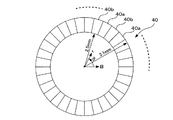
また、図1に表された機構部の一部としての可動ミラーユニット16に設けられた可動ミラーアクチュエータ(図示せず)によって可動ミラー16aの回動の角度は制御され、対物レンズ28を通過してホログラム記録媒体48に照射される光ビームを紙面の左右方向(紙面の短手方向)である(タンジェンシャル方向)に移動させるようになされている。また、トラックキング可動部34は、フーリエ変換レンズ42、1/4波長板26および対物レンズユニット36を一体としてラジアル方向に微少量だけ移動するようになされている。このトラックキング可動部34の移動は、機構部の一部である可動部アクチュエータ60を用いておこなわれるようになされている。すなわち、可動ミラーアクチュエータは、光スポットをタンジェンシャル方向に移動させる機構部である。また、トラックキング可動部34は、光スポットをトラッキング方向に移動させる機構部である。
Further, the rotation angle of the
また、図1に表された他の機構部としては、ホログラム記録媒体48を回転させる機構部分およびフォーカスサーボをおこなう機構部が示されている。ホログラム記録媒体48はターンテーブルに例えば、マグネットチャッキングによって装着されるようになされ、このターンテーブルはスピンドルモータ33の回転軸と固着されている。このような機構部の構造によって、スピンドルモータ33の駆動力でホログラム記録媒体48を回転させるようになされている。スピンドルモータ33とスピンドルモータ基台58との間にはフォーカスアクチュエータ55が装着され、図1に示す図の紙面の表裏方向(フォーカス方向)のホログラム記録媒体48とスピンドルモータ基台58との間の距離を変化させることができるようになされている。また、スライド送りモータ56の回転軸に固着され、この回転軸とともに回転する第1の歯車57aと、スピンドルモータ基台58に固着された第2の歯車57bとが噛み合って、スライド送りモータ56の回転にともなって、ホログラム記録媒体48の全体を同心円の中心を支軸として回転させることができるようになされている。このようなスライド送り機構は、ホログラム記録媒体48の半径に相当する距離に渡り、トラッキングサーボの低域成分の大きな量の変位に対応してホログラム記録媒体48を移動させることができるようにされている。
Further, as the other mechanism units shown in FIG. 1, a mechanism unit for rotating the
また、ホログラム記録再生装置1は温度検出部70を有している、温度検出部70は、ホログラム記録媒体48の温度を検出するものであって、熱電対温度計、ホログラフィ温度検出器、水銀温度計などを用いて、ホログラム記録媒体48の温度またはホログラム記録媒体48の付近の温度を電気信号に変換して検出する部分であり、電気信号に変換して検出された温度信号は制御部100に入力される。
Further, the hologram recording / reproducing
(記録の作用の概要説明)
光学部の各部の作用と併せてホログラムへの記録がどの様におこなわれるかについて、順に説明をする。
(Summary of action of recording)
A description will be given in order of how the recording to the hologram is performed together with the action of each part of the optical part.
レーザ光源10は、例えば、レーザ光の波長が405nm(ナノ・メータ)とされているレーザ(いわゆる、青色レーザ)を有し、青色レーザからの光ビームを外部共振器に通過させ、光ビームの波長を変化できるようにされている。アイソレーター11は、レンズ等の反射によって戻光が戻った場合でも、外部共振器型レーザを構成する青色レーザに戻光が戻ることを防いで、シングルモードの発振を維持するためのものである。レーザ光の波長は、制御部100からの信号によって制御される。
The
シャッター12は光ビームを透過、または、遮蔽するための素子であり、制御部100からの信号によって光ビームが透過させられるか、遮蔽されるかが制御される。フーリエ変換レンズ13およびフーリエ変換レンズ14は光ビームの径を拡大するためのものである。このようにして径を拡大された光ビームは、可動ミラー16aに入射して、偏光ビームスプリッタ20によって光ビームは空間変調器19に向かうように反射する。このようにして、空間変調器19の所望の領域、すなわち、後述する空間変調器19の参照光領域19aおよび信号光領域19b(図3を参照)に光ビームを照射することが可能とされる。
The
空間変調器19は、上述する参照光領域および信号光領域の各々に所定のパターンを表示して、光ビームに空間的な変調を施して参照光と信号光とを得るためのものであり、例えば、反射型強誘電体液晶が採用されている。反射型強誘電体液晶は2次元に微細なサイズに分割されたピクセルの集合として形成されている。各々のピクセルは、例えば、10μmの正方形として形成されている。また空間変調器19の縦と横に各々1000個のピクセルが配置され、空間変調器19に配置されるピクセルの総数は、1000×1000=1000000個とされており、このピクセルによって、参照光領域および信号光領域の各々、さらには、再生光領域が形成されようになされている。そして、上述した所定のパターンとは、このピクセルの各々に照射される光ビームを反射するようにするか、反射しないようにするかの組み合わせをピクセル単位で選ぶものであって、このパターンの形態は制御部100によって制御されている。
The
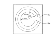
図2は、参照光領域および信号光領域の各々表示されるパターンを示している。図2の紙面の色と同じ部分(以下、白部と称する)は光ビームを反射する部分で、黒い部分(以下、黒部と称する)は光ビームを反射しない部分である。ここで、制御部100においては記録データを2値のブロック符号としてエンコードして、「1」を白い部分に、「0」を黒い部分に対応させている。内側の多角形が信号光を発生するための信号光領域であり、参照光を発生する参照光領域は明るいドーナツ部分であり、同図のように白部と黒部とをランダムに配置する方式もあるし、全部を白部とする方式もあり、様々である。多角形とドーナツの間に黒い部分があり、これによって信号光と参照光を分けている。
FIG. 2 shows patterns displayed in the reference light region and the signal light region, respectively. A portion (hereinafter referred to as a white portion) that is the same as the color of the paper surface of FIG. 2 is a portion that reflects the light beam, and a black portion (hereinafter referred to as a black portion) is a portion that does not reflect the light beam. Here, the
図3は、図2に示される参照光領域19aおよび信号光領域19bの範囲を具体的な寸法によって示すものである。
FIG. 3 shows the ranges of the
再び、図1に示す各部の説明に戻る。空間変調器19で変調を受けた参照光および信号光はその偏光方向が入射光に対してπ/2異なって直交するので偏光ビームスプリッタ20を透過してフーリエ変換レンズ21の方向に向かう。フーリエ変換レンズ21およびフーリエ変換レンズ24を通過した光ビームは、偏光ビームスプリッタ27に入射する。
Returning to the description of each unit shown in FIG. Since the polarization direction of the reference light and the signal light modulated by the spatial
偏光ビームスプリッタ27は、参照光および信号光をフーリエ変換レンズ41の方向に向かわせるとともに、後述する回折光をフーリエ変換レンズ29の方向に向かわせるためのものである。
The
フーリエ変換レンズ41およびフーリエ変換レンズ42を通過した光ビームは、さらに、1/4波長板26を透過し、対物レンズユニット36に配されたミラーによって方向が変えられた光ビームは対物レンズで集光されて、参照光と信号光とによって形成される干渉縞に応じたホログラムをホログラム記録媒体48の記録材料48bの中に形成してホログラムの記録がおこなわれる。
The light beam that has passed through the
(再生の作用の概要説明)
光学部の各部の作用と併せてホログラムからの再生がどの様におこなわれるかについて、簡単に順に説明をする。
(Summary of the effect of regeneration)
A brief description will be given of how the reproduction from the hologram is performed together with the action of each part of the optical unit.
ホログラムの再生に際しては、参照光領域19aは、再生光領域として機能し参照光領域19aには記録時におけると同様なパターンが表示されるのが、従来は一般的である。なお、本実施形態では、記録における参照光領域19aと再生における再生光領域とは異なる領域であることを特徴とするが、この点については、後に詳細に説明をする。また、信号光領域19bのピクセルはすべて黒部とされ、信号光領域19bからは光ビームを反射しないようになされる。空間変調器19にこのようなパターンを表示する制御は、制御部100から空間変調器19に信号を供給することによって制御される。
When reproducing a hologram, the
空間変調器19にこのようなパターンを表示した後に、記録をおこなうときと同様に光ビームを空間変調器19に照射して、光ビームを変調して、変調された光ビームは、記録時におけると同様に、途中の光学部品を通過して最終的に対物レンズ28で集光されて、ホログラム記録媒体48の記録材料48bに集光される。記録材料48bに形成されているホログラムに応じて発生する回折光は、ホログラム記録媒体48の図示しない反射膜で反射されて、再び、対物レンズ28、1/4波長板26を通過して、他の光学部材を通過して、偏光ビームスプリッタ27に至る。
After displaying such a pattern on the
ここで、1/4波長板26は、行きの経路では、青色光ビームの偏光を直線偏光から円偏光に変換し、帰りの経路では、1/4波長板26に入射する青色光ビームの偏光が円偏光である場合には円偏光から直線偏光に変換する。このときの戻光の青色光ビームの偏光面は行きの偏光面とπ/2異なって直交することとなるので、偏光ビームスプリッタ27に至った回折光は、フーリエ変換レンズ29の方向へ向かうこととなる。
Here, the quarter-
ミラー30は、フーリエ変換レンズ29からの回折光を反射してフーリエ変換レンズ31に導くものであり、ミラー30は光ビームの通過する光路を折り曲げて光学部のサイズを小さくするために用いられている。また、フーリエ変換レンズ29とフーリエ変換レンズ31とは、倍率が調整された実像がイメージセンサ32に形成されるようにするためのものである。イメージセンサ32は、シーモス・センサ(CMOSセンサ)、チャージ・カップルト・デバィス(CCD)等に代表される光学受光素子であって、微細に分割された複数の受光素子(ピクセル)が2次元に配置され、各々の受光素子を照射する回折光の明暗に応じた電気信号を各々のピクセルで検出するものである。制御部100ではこの電気信号を入力して記録データを再生するための信号処理をおこなうようになされている。ここで、記録データは、従来のCD、DVDのような光ディスクと比較すると、1×10³〜1×106 bit(ビット)のデータ(1ペ−ジ分のデータ)を一度に記録、再生できるのが特徴である。
The
(ホログラム記録媒体の熱膨張の影響について)
図4は、ホログラム記録媒体48の温度と、レーザ光源10から出射される最適なレーザ波長(光ビーム波長)との関係を示すグラフであり、図5は、ホログラム記録媒体48の温度と、参照光および再生光の最適な入射角度(後述する図6を参照)の範囲である入射角度範囲または参照光領域19a1(後述する図6を参照)および再生光領域19a2(後述する図7を参照)との関係を示すグラフである。このグラフは、計算式によって求めた結果であるが、実験結果との一致度が極めて高いものである。この計算結果は、背景技術の説明において、図17を用いて説明をしたホログラム記録媒体48における基板48aおよび基板48cと記録材料48bの熱膨張の違いから発生する現象を解析して得たものである。
(Influence of thermal expansion of hologram recording medium)
FIG. 4 is a graph showing the relationship between the temperature of the
図4および図5に示すグラフの意味するところは、例えば、記録時におけるホログラム記録媒体48の温度が25℃、参照光の入射角度が31.3°〜36.9°(参照光領域19a1の範囲は2.6mm〜3.0mm)、レーザ波長405nmの条件で記録した場合には、再生時において、ホログラム記録媒体48の温度が25℃の条件下では、再生光の入射角度は31.3°〜36.9°(再生光領域19a2の範囲は2.6mm〜3.0mm)、レーザ波長405nmの条件で再生するのが最も望ましく、また、別の例では、再生時において、ホログラム記録媒体48の温度が35℃の条件下では、再生光の入射角度は31.1°〜36.6°(再生光領域19a2の範囲は2.58mm〜2.98mm)、レーザ波長402.3nmの条件で再生するのが最も望ましく、さらに、別の例では、再生時において、ホログラム記録媒体48の温度が15℃の条件下では、再生光の入射角度は31.6°〜37.1°(再生光領域19a2の範囲は2.62mm〜3.02mm)、レーザ波長407.7nmの条件で再生するのが最も望ましく、これらの条件で再生する場合に最も良好なる再生特性が得られることを意味している。
The meanings of the graphs shown in FIGS. 4 and 5 are, for example, that the temperature of the
また、図4および図5の用い方の別の例を挙げる。記録時におけるホログラム記録媒体48の温度が35℃である場合には、参照光の入射角度31.3〜36.9°(再生光領域19a2の範囲は2.58mm〜2.98mm)、レーザ波長402.3nmの条件で記録するのが最も望ましく、このような条件で記録すれば、上述したように、図4および図5のグラフを参照することによって、再生時のホログラム記録媒体48の温度が如何なる場合であっても、図4および図5を参照して、最適なるレーザ波長および最適なる再生光の入射角度(再生光領域19a2の範囲)を定めることができる。
Another example of how to use FIGS. 4 and 5 will be given. When the temperature of the
ここで、図4および図5にグラフとして示すデータの内容は、制御部100の内部に配されたラム(RAM)等に記憶されているので、制御部100は温度検出部70から温度を検出し、制御部100は、RAMを参照して、この温度に対応するレーザ波長と参照光または再生光の入射角度(参照光領域19a1または再生光領域19a2の範囲)を読み出し、制御部100が空間変調器19を制御することによって、最適なる記録および/または再生の条件を設定することができる。
Here, the contents of the data shown as graphs in FIGS. 4 and 5 are stored in a ram (RAM) or the like arranged inside the
(第1実施形態)
図6ないし図8を参照して第1実施形態について詳細に説明をする。図6は、記録時における、空間変調器19(図1を参照)に表示される参照光領域19a1と信号光領域19b、対物レンズ28(図1を参照)、ホログラム記録媒体48(図1を参照)との相互の関係を光ビームの進行方向の沿った断面図として模式的に示すものである。
(First embodiment)
The first embodiment will be described in detail with reference to FIGS. 6 shows a reference light area 19a1 and a
図7および図8は、再生時における、空間変調器19に表示される再生光領域19a2と信号光領域19b、対物レンズ28、ホログラム記録媒体48との相互の関係を光ビームの進行方向の沿った断面図として模式的に示すものである。正確には図6ないし図8において、ホログラム記録媒体48の表面で光は屈折するが、実施形態の説明の本質には影響を与えないために、図6ないし図8においては、記載は省略してある。ここで、図6に示されている入射角度A1は、特定のピクセル(このピクセルの空間的位置は変化するが、このピクセルが「1」であるか「0」であるかの信号は特定されている所定の電気的に特定されるピクセル、このようなピクセルの位置を電気的位置と称して以下用いる)から反射する参照光の入射角度を示すものである。図7に示されている入射角度A2および図8に示されている入射角度A3は、この特定のピクセルから反射する再生光の入射角度を示すものである。ここで、入射角度A1の光ビームと入射角度A2の光ビーム、さらには、後述する入射角度A3の光ビームとがホログラムの同一点を通過するようにするのが、本実施形態の特徴である。また図6ないし図8では空間変調器19で反射する光ビームを、各画素の中心から発する点光源のように記載しているが、実際は参照光領域19a1の全領域、再生光領域19a2の全領域、信号光領域19bの全領域で反射して連続的に分布する。
7 and 8 show the relationship between the reproduction light area 19a2 displayed on the
図6に示すように、空間変調器19の外周部に参照光領域19a1が配され、空間変調器19の内周部に信号光領域19bが配されている点は、図3に示すと同様である。ここで、記録時におけるホログラム記録媒体の温度が25℃であるとして以下の説明をおこなう。参照光領域19a1および信号光領域19bの各々の領域で反射された光ビームは、広がりつつ、対物レンズ28に到達し、対物レンズ28を通過後は平行光となってホログラム記録媒体48を照射する。
As shown in FIG. 6, the reference light region 19a1 is arranged on the outer periphery of the
実施形態における具体的なパラメータとしては、対物レンズの焦点距離が5mm、対物レンズ28の開口(N.A.)が0.6、参照光領域19a1および信号光領域19bの各々を形成するピクセル(画素)が10μm(マイクロ・メータ)の正四角形、ホログラム記録媒体48メディアの屈折率が1.5のとき、各画素からの平行光の幅は405μmとなるように設定されている(この計算においてはホログラム記録媒体48での屈折を考慮してある。)。また、信号光領域19bの範囲は、図3に示すように、空間変調器19での半径で2.3mm以内(この値は温度によらず固定)とされ、ホログラム記録媒体の温度が温度25℃において参照光領域の範囲は2.6mm〜3.0mmの範囲とされている。この範囲設定は制御部100から出力される電気信号によって任意に設定することができる。
As specific parameters in the embodiment, the focal length of the objective lens is 5 mm, the aperture (NA) of the
上述した条件で記録した場合、信号光領域19bを暗部として再生する場合の、再生時におけるホログラム記録媒体48の温度が10℃程度異なれば、上述したホログラム記録媒体48における熱膨張の影響によって、参照光領域19a1と再生光領域19a2とを同じ領域とし、参照光の入射角度と再生光の入射角度とを共に入射角度A1とし、光ビームの波長を同じとする場合には、記録データを再生できない。本実施形態では、この点を考慮して参照光領域19a1と再生光領域19a2とを独立して各々設定するようにしている(参照光領域19a1と再生光領域19a2とが一致する場合も含む)。
When recording is performed under the conditions described above, if the temperature of the
図7は、上述した条件で記録されたホログラム記録媒体48を、例えば、ホログラム記録媒体48の温度が10℃低い15℃の温度で再生する場合における、最適なる再生光領域19a2を示す図である。再生光領域19a2の範囲は、図4および図5を参照して説明した、本実施形態の記録再生の原理を基礎づけるデータによって特定され、この場合であれば、再生光領域19a2の範囲は2.62mm〜3.02mmである。再生光領域19a2の範囲を2.62mm〜3.02mmとする制御は、空間変調器19に制御部100から指令を出しておこなわれる。具体的には、画素の一辺が10μmの正方形の場合、内半径で2画素、外半径で2画素、それぞれ、外側にずらすことになる。なお、レーザ波長は、上述したように、レーザ光源10に制御部100から指令を出して、407.7nmに設定される。また、入射角度A2は、入射角度A1よりも大きく設定されることとなる。
FIG. 7 is a diagram showing an optimum reproduction light region 19a2 when the
図8は、上述した条件で記録されたホログラム記録媒体48を、例えば、ホログラム記録媒体48の温度が10℃高い35℃の温度で再生する場合における、最適なる再生光領域19a2を示す図である。再生光領域19a2の範囲は、図4および図5を参照して説明した、本実施形態の記録再生の原理を基礎づけるデータによって特定され、この場合であれば、再生光領域19a2の範囲は2.58mm〜2.98mm)、レーザ波長402.3nmである。再生光領域19a2の範囲を2.58mm〜2.98mm(再生光の入射角度は31.1°〜36.6°に対応する)とする制御は、空間変調器19に制御部100から指令を出しておこなわれる。
FIG. 8 is a diagram showing an optimum reproduction light region 19a2 when the
具体的には、画素の一辺が10μmの正方形の場合、内半径で2画素、外半径で2画素、それぞれ、内側にずらすことになる。しかしながら、画素の一辺が10μmの正方形の場合には、通常は、所望の半径に対して、ぴったりの半径では照射できない。(上記例では、2画素ずらすと内半径は2.580mmとなる。このため、この場合には、幾分、内径側を予定よりも越えるような再生光領域19a2を設定する。この場合には、再生に必要な入射角度の範囲をカバーしているので記録データを問題なく再生できる。幾分余分な入射角度を有する光ビームはブラッグ条件を満たさないので再生において、障害とはならない。
なお、レーザ波長は、上述したように、レーザ光源10に制御部100から指令を出して、402.3nmに設定される。また、入射角度A3は、入射角度A1よりも小さく設定されることとなる。
Specifically, in the case of a square having a side of 10 μm, the inner radius is shifted by 2 pixels and the outer radius is shifted by 2 pixels, respectively. However, in the case of a square having a side of 10 μm, it is usually impossible to irradiate with an exact radius with respect to a desired radius. (In the above example, when the two pixels are shifted, the inner radius becomes 2.580 mm. For this reason, in this case, the reproducing light region 19a2 is set so as to slightly exceed the inner diameter side. Since the incident angle range necessary for reproduction is covered, the recorded data can be reproduced without any problem.Because the light beam having a somewhat extra incident angle does not satisfy the Bragg condition, there is no obstacle in reproduction.
As described above, the laser wavelength is set to 402.3 nm by issuing a command to the
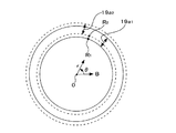
図9、図10は空間変調器19の反射面に形成される参照光領域19a1および再生光領域19a2を各々示すものである。図9は図7に示す断面図に対応し、図10は図8に示す断面図に対応するものである。
FIGS. 9 and 10 show the reference light region 19a1 and the reproduction light region 19a2 formed on the reflection surface of the
図7では、参照光領域19a1は再生光領域19a2に対して、より、内周側に配置される。この場合、図9においては、参照光領域19a1および再生光領域19a2の各々に属するピクセルの空間的位置を円柱座標で示せば、参照光領域19a1の一点は点R1(実際には一辺が10μmの正方形)で表される、この点が白部であるか黒部であるかは、電気的位置に応じて制御部100が「1」または「0」の信号によって制御している。そして、温度が10℃低い15℃の温度で再生する場合には、同じ電気的位置である参照光領域19a1の点R1は、再生光領域19a2の点R2に、空間的に写像されることとなる。すなわち、空間的な位置(θ1、r1)は空間的な位置(θ1、r2)に写像されたことになる。ここで、θ1は点R1を円座標で表す場合の基準線Bからの角度、r1は点R1を円座標で表す場合の円の中心Oからの半径であり、r2は点R2を円座標で表す場合の円の中心Oからの半径である。ここで、同じ空間的な電気位置は、同一の角度を有し、記録時と再生時とのホログラム記録媒体48の温度に応じて異なる半径を有する点に写像されることとなり、一次近似として数式1の変換式が点R1の半径r1と点R2の半径r2の両者に間に成立する。ここで、kは定数、Twは記録時の温度であり、この場合には25℃である。また、Trは再生時の温度であり、この場合には15℃である。また、点R1の角度と点R2の角度については同一のθ1である。
In FIG. 7, the reference light region 19a1 is arranged closer to the inner periphery than the reproduction light region 19a2. In this case, in FIG. 9, if the spatial positions of the pixels belonging to each of the reference light region 19a1 and the reproduction light region 19a2 are indicated by cylindrical coordinates, one point of the reference light region 19a1 is a point R1 (actually, one side is 10 μm). Whether the point is a white portion or a black portion, which is represented by a square), is controlled by the
![]()
![]()
図8では、参照光領域19a1は再生光領域19a2に対して、より、外周側に配置される。この場合、温度が10℃高い35℃の温度で再生する場合には、同じ電気的位置である参照光領域19a1の点R1は、再生光領域19a2の点R3に、空間的に写像されることとなる。すなわち、空間的な位置(θ1、r1)は空間的な位置(θ1、r3)に写像されたことになる。r3は点R3を円座標で表す場合の円の中心Oからの半径である。ここで、数式1のr2をr3に置き換え、Twに25℃を代入し、Trに35℃を代入して、点R1が写像される点である点R3の半径r3を得ることができる。
In FIG. 8, the reference light region 19a1 is disposed closer to the outer periphery than the reproduction light region 19a2. In this case, when reproduction is performed at a temperature of 35 ° C., which is 10 ° C. higher, the point R1 of the reference light region 19a1 at the same electrical position is spatially mapped to the point R3 of the reproduction light region 19a2. It becomes. That is, the spatial position (θ1, r1) is mapped to the spatial position (θ1, r3). r3 is a radius from the center O of the circle when the point R3 is expressed in circular coordinates. Here, by replacing r2 in
上述した、第1実施形態では、参照光領域19a1および再生光領域19a2の各々に表示されるパターン(これらの領域を形成する各々のピクセルの白部または黒部の分布の態様)は、どのようなものでも、数式1の関係が同じ電気的な位置にあるピクセルについて成立すれば、特に、制限があるものではなく、所定のパターン、ランダムパターン、全部が白部のパターン等のいかなるパターンであっても良いものである。
In the first embodiment described above, the pattern displayed in each of the reference light region 19a1 and the reproduction light region 19a2 (the distribution mode of the white portion or the black portion of each pixel forming these regions) However, there is no particular limitation as long as the relationship of
また、上述した第1実施形態においては、参照光領域19a1と再生光領域19a2との相互の空間的な位置関係を記録時および再生時のホログラム記録媒体48の温度に応じて変化させるとともに、レーザ波長も同時に変化させるようにしたが、記録時と再生時の温度差が小さい場合には、レーザ波長を変化させることなく、参照光領域19a1と再生光領域19a2との相互の空間的な位置関係を変化させるだけでも、記録再生特性の改善効果を十分に得ることができるものである。
In the first embodiment described above, the spatial positional relationship between the reference light region 19a1 and the reproduction light region 19a2 is changed according to the temperature of the
(第2実施形態)
図11は空間変調器19の反射面に形成される参照光領域19a1および再生光領域19a2を各々示す図である。図11に沿って第2実施形態の説明をする。ホログラム記録再生装置1の使用温度範囲が5℃〜45℃の範囲で動作するように設計されているとする。このときには、ホログラム記録媒体48の温度も、ホログラム記録再生装置1の使用温度範囲に応じて5℃〜45℃の範囲で記録と再生の動作がおこなわれることとなる。この場合において、図5を参照すれば、再生光領域19a2は半径で2.56mmから3.04mmの間に分布する。第2実施形態では、温度によらず、再生光領域19a2の領域をこの範囲まで拡大して、この範囲の再生光をすべて照射する。一方、参照光領域19a1は、温度に応じてその範囲を変化させる。これによって使用温度範囲のどの温度においても必要とする入射方向の再生光成分がホログラム記録媒体48に配された記録材料48bに照射され、良好な再生が可能となる。余計な再生光を記録材料48bに照射しても支障がないのは、本来の入射角度ではない入射角度を有する余分な光ビームは、ブラッグ条件を満たさないので影響を与えないためである。この場合には、再生光領域19a2は、すべて、白部とすることが望ましい。また、記録時と再生時との温度差が比較的小さい場合には、レーザ波長を一定に保っても良好なる記録再生特性が得られる。しかしながら、記録時と再生時との温度差が比較的大きい場合には、レーザ波長を図4に示すグラフに応じて変化させることによって、さらに良好なる記録再生特性を得ることができる。また、参照光領域19a1は、ホログラム記録媒体の温度が変化しても固定値を採用し、再生光領域19a2も同様に固定値とするようにしても良い。この場合には、再生光領域19a2の範囲が、ホログラム再生装置の使用温度範囲内において、ホログラムに対して、参照光を照射すべき範囲の全てをカバーするように形成されるものであれば、再生特性に問題が生じることはない。
(Second Embodiment)
FIG. 11 is a view showing a reference light region 19a1 and a reproduction light region 19a2 formed on the reflection surface of the
(第3実施形態)
図12は第3実施形態に係るホログラム記録再生装置2を示す図である。位相マスクを空間変調器19に接するように、あるいは図12に示すように空間変調器19の実像ができる位置に位相マスク40を配置することによって、さらに、0次光が記録材料48b(図17を参照)において生じるのを防ぐことができるという効果を得ることができる。0次光が生じると、記録時においては、局所的にエムナンバー(M/#)を浪費し、多重記録をおこなう場合の多重の回数である多重記録回数が減少する。また再生時においては、光ビームが記録材料48bの特定の位置に集中することによって記録材料48bの劣化を促進してしまう。このために画素ごとに位相を変え、記録材料48bの内部の0次光が照射される位置での各々の画素からの光ビームの振幅の和をほぼ0にする(打ち消しあうようにする)のが、第3実施形態において位相マスクを使用する理由である。
(Third embodiment)
FIG. 12 is a diagram showing a hologram recording / reproducing apparatus 2 according to the third embodiment. By placing the
第1実施形態では、参照光領域19a1および再生光領域19a2の各々の領域の範囲を変化させ、第2実施形態では、参照光領域19a1の領域の範囲を変化させ、これによって、参照光および再生光または参照光の入射角を半径方向に変える。このような実施形態に、さらに、位相マスク(例えば、位相マスク40)を備える場合においては、その際に位相を記録時におけると同様に保たないと良好な再生特性を得ることができない。このため、参照光領域19a1および再生光領域19a2の各々の領域の範囲が変化する場合であっても位相マスクで発生される位相は同一でなければならない。このような位相マスクの一例として、放射状の位相マスクが挙げられる。 In the first embodiment, the range of each of the reference light region 19a1 and the reproduction light region 19a2 is changed, and in the second embodiment, the range of the reference light region 19a1 is changed, whereby the reference light and the reproduction light are reproduced. The incident angle of light or reference light is changed in the radial direction. In such an embodiment, when a phase mask (for example, the phase mask 40) is further provided, good reproduction characteristics cannot be obtained unless the phase is maintained in the same manner as during recording. For this reason, even when the ranges of the reference light region 19a1 and the reproduction light region 19a2 change, the phases generated by the phase mask must be the same. An example of such a phase mask is a radial phase mask.
図13は、放射状の位相マスクの例として位相マスク40の平面図を示すものである。図13は、位相マスクの光ビームの進行方向に垂直な断面図を示すものであり、その内半径と外半径は、第1実施形態および第2実施形態で示した参照光領域および再生光領域の全範囲をカバーしており、位相マスクの内半径は、例えば、半径2.5mmとされ、外半径は、例えば、半径3.1mmとされている。符号40aを付した部分は凸部(図14(A)の符号40aの部分を参照)、符号40bを付した部分は凹部(図14(A)の符号40bの部分を参照)を示すものであり、凹部と凸部とが交互にドーナツ状に配置されている。図14は種々の形態の位相マスクの断面を示す図である。位相マスク40としては、図14(A)ないし図14(C)のいずれを採用するものであっても良い。図14(A)は階段状の凹凸を有するものであり、符号40aを付した凸部と符号40bを付した凹部との段差がmλ/(2n)とされている。ここでmは奇数、λは光ビームの波長、nは屈折率である。また、図14(B)は正弦波(Sin)状の凹凸を有するものであり、また、図14(C)はテーパ形状の階段状の凹凸を有するものである。
FIG. 13 shows a plan view of a
数式2は、このような位相マスクを用いる場合において、0次光を打ち消せることを計算で確認するための式である。ここで、図14(A)ないし図14(C)に示す位相マスクの断面図の頂上と底の位相差が2πであり、円周の1周の間にp周期の凹凸の変化を有するものとする。pは整数である。 Expression 2 is an expression for confirming by calculation that the zero-order light can be canceled when such a phase mask is used. Here, the phase difference between the top and the bottom of the cross-sectional views of the phase mask shown in FIGS. 14A to 14C is 2π, and there is a change in the unevenness of the p period between one circumference. And p is an integer.

ここで、0次光の強度I0は、数式3で表される。E*はEの共役関数である。 Here, the zero-order light intensity I0 is expressed by Equation 3. E * is a conjugate function of E.
また、頂上と底の位相差が2×2π、1周の間にp周期であれば、数式2のpを2pで置きかえればよく、結果は同様となる。 Further, if the phase difference between the top and the bottom is 2 × 2π and p cycles between one round, the p in Equation 2 may be replaced with 2p, and the result is the same.
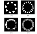
図15は位相マスクの凹凸の繰り返し数を種々に変化させる例を示す図である。図15で白い部分は凸部、黒い部分は凹部に対応するものである。図15(P1)は16分割、すなわち1周の間に8周期の凹凸の繰り返しを有する位相マスクを示すものである。図15(P2)は32分割、すなわち1周の間に16周期の凹凸の繰り返しを有する位相マスクを示すものである。図15(P3)は64分割、すなわち1周の間に32周期の凹凸の繰り返しを有する位相マスクを示すものである。図15(P4)は128分割、すなわち1周の間に64周期の凹凸の繰り返しを有する位相マスクを示すものである。 FIG. 15 is a diagram showing examples in which the number of repetitions of the unevenness of the phase mask is variously changed. In FIG. 15, the white portion corresponds to the convex portion and the black portion corresponds to the concave portion. FIG. 15 (P1) shows a phase mask having 16 divisions, that is, a repetition of irregularities of 8 cycles in one round. FIG. 15 (P2) shows a phase mask having 32 divisions, that is, a repetition of 16 periods of irregularities in one round. FIG. 15 (P3) shows a phase mask having 64 divisions, that is, having 32 cycles of irregularities in one round. FIG. 15 (P4) shows a phase mask having 128 divisions, that is, having 64 repetitions of irregularities in one round.
図16は、位相マスクの周期を種々に変化させた場合における、ホログラム記録媒体48における光ビームのピーク強度と、1周の間の位相マスクの凹凸の繰り返し数の2倍の数である分割数と、の関係を示すグラフである。グラフの横軸は、分割数を示し、縦軸は、1または複数個生じる光ビームの強度が大きくなる点の中の最大の強度(ピーク強度)を示すものである。点P1は、16分割のときのピーク強度を示し、点P2は、32分割のときのピーク強度を示し、点P3は、64分割のときのピーク強度を示し、点P4は、128分割のときのピーク強度を各々示すものである。点Pmは位相マスクがないときのピーク強度を示すものであり、点Prは2レベルのランダムなパターンを有する位相マスクを用いる場合におけるピーク強度を示すものである。図16は、位相マスクがピーク強度を低下させる効果があることを示すとともに、ピーク強度を抑圧する効果は、位相マスクの分割数が大きくなればなるほど大きくなることを示している。
FIG. 16 shows the number of divisions that is twice the peak intensity of the light beam in the
なお、図14(A)ないし図14(C)、数式2では、位相マスクは規則的な形状を有するものとして説明をしたが、原理的には、位相マスクの形状は、点対称である必要はなく、参照光領域が形成される範囲と再生光領域が形成される範囲との各々が変化する場合において、ホログラム記録媒体の温度に応じて形状が変化するホログラムの同一の点を照射する光ビームに対しては、同一の位相特性を付与するものであればどの様なものでも良い。より具体的には、参照光領域および再生光領域がドーナツ状の形状を有する領域として形成される場合においては、0次光を打ち消す形状であって、かつ「放射状」であれば良い。ここで、位相マスクは、参照光領域および参照領域と1体1に対応するものである。このような、点対称ではない位相マスクの場合にも上述の点対称の場合におけると同様に、制御部100によって位相マスクの態様の制御をすることができる。
14A to 14C and Equation 2 have been described on the assumption that the phase mask has a regular shape. However, in principle, the shape of the phase mask needs to be point-symmetric. No, the light that irradiates the same point of the hologram whose shape changes according to the temperature of the hologram recording medium when each of the range in which the reference light region is formed and the range in which the reproduction light region is formed Any beam may be used as long as it provides the same phase characteristics. More specifically, when the reference light region and the reproduction light region are formed as regions having a donut shape, the shape may be a shape that cancels the zero-order light and is “radial”. Here, the phase mask corresponds to the reference light region, the reference region, and one
また、空間変調器19は、信号光領域19b、参照光領域19a1および再生光領域19a2の各々の領域に属する空間変調器19のピクセル(画素)の大きさを10μmの正方形として説明をしたが、位相マスクのピクセルと、空間変調器19のピクセルとが同じ形である必要はない。たとえば、位相マスクの信号光領域19bに対応する部分の形状は10μmの正方形として、位相マスクの参照光領域19a1および再生光領域19a2に対応するピクセルの形状は、正方形ではなく、ドーナツ型としても良い。そして、そのドーナツの幅(ドーナツ形状を形成する外周円と内周円との各々の円の半径の差)を例えば10μm程度の幅となるようにして1ピクセルを形成し、このような10μmステップのドーナツの幅を有する複数のピクセルの集合で形成される参照光領域19a1および再生光領域19a2の各々の形態を制御部100によって、ピクセルごとに制御するようにしても良い。
The
第3実施形態によれば、第1実施形態および第2実施形態から得られる効果と同様に、光ビームの入射角度範囲を適切にして記録再生特性を良好なものとする効果に加えて、光ビームが特定の部分に集中してピーク強度を大きくすることを防止できる。そして、ピーク強度を大きくすることを防止できる効果としては、記録時においては、局所的にエムナンバー(M/#)を浪費することが防止でき、多重記録をおこなう場合の多重の回数である多重記録回数を増大させることができる。また再生時においては、光ビームが記録材料の特定の位置に集中することを防止して、記録材料の劣化が生じることを防止できる。 According to the third embodiment, in addition to the effect obtained from the first embodiment and the second embodiment, in addition to the effect of making the incident angle range of the light beam appropriate and improving the recording / reproducing characteristics, the light It is possible to prevent the beam from concentrating on a specific portion and increasing the peak intensity. As an effect of preventing the peak intensity from being increased, it is possible to prevent the M number (M / #) from being wasted locally during recording, and the number of times of multiplexing when multiplexing recording is performed. The number of recordings can be increased. Further, at the time of reproduction, it is possible to prevent the light beam from concentrating on a specific position of the recording material and to prevent the recording material from deteriorating.
上述した実施形態の説明に用いた数値は、本願の願書に記載した発明者らが実験で用いている典型値である。例えば、図4および図5に示すグラフは異なる記録材料を有するホログラム記録媒体を用いれば異なるものであり、空間変調器における信号光領域と参照光領域の該当半径も説明に用いた値に限られるわけではない。 The numerical values used in the description of the above-described embodiment are typical values used in experiments by the inventors described in the application of the present application. For example, the graphs shown in FIGS. 4 and 5 are different if hologram recording media having different recording materials are used, and the corresponding radii of the signal light region and the reference light region in the spatial modulator are also limited to the values used in the description. Do not mean.
1、2 ホログラム記録再生装置、 10 レーザ光源、 11 アイソレーター、 12 シャッター、 13、14、21、24、29、31、42 フーリエ変換レンズ、 16 可動ミラーユニット、 16a 可動ミラー、 19 空間変調器、 19a、19a1 参照光領域、 19a2 再生光領域、 19b 信号光記録領域、 20、27 偏光ビームスプリッタ、 26 1/4波長板、 28 対物レンズ、 30 ミラー、 32 イメージセンサ、 33 スピンドルモータ、 34 トラックキング可動部、 36 対物レンズユニット、 40 位相マスク、 48 ホログラム記録媒体、 48a、48c 基板、 48b 記録材料、 55 フォーカスアクチュエータ、 56 モータ、 57a、57b 歯車、 58 スピンドルモータ基台、 60 可動部アクチュエータ、 70 温度検出部、 100 制御部、 A1、A2、A3 入射角度、 d1、d2、d3 間隔 1, 2 Hologram recording / reproducing apparatus, 10 Laser light source, 11 Isolator, 12 Shutter, 13, 14, 21, 24, 29, 31, 42 Fourier transform lens, 16 Movable mirror unit, 16a Movable mirror, 19 Spatial modulator, 19a , 19a1 Reference light region, 19a2 Reproduction light region, 19b Signal light recording region, 20, 27 Polarizing beam splitter, 26 1/4 wavelength plate, 28 Objective lens, 30 Mirror, 32 Image sensor, 33 Spindle motor, 34 Track king movable Part, 36 objective lens unit, 40 phase mask, 48 hologram recording medium, 48a, 48c substrate, 48b recording material, 55 focus actuator, 56 motor, 57a, 57b gear, 58 spindle motor Data base, 60 movable part actuator, 70 temperature detection part, 100 control part, A1, A2, A3 incident angle, d1, d2, d3 interval
Claims (9)
前記参照光を発生するための参照光領域と前記再生光を発生するための再生光領域との各々が形成される空間変調器と、
前記参照光領域が形成される範囲と前記再生光領域が形成される範囲との各々を制御する制御部と、を具備し、
記録をするときの前記ホログラム記録媒体の温度に応じて、前記参照光領域が形成される範囲を第1所定範囲とすることによって前記ホログラム記録媒体への前記参照光の入射角度の範囲を第1所定角度範囲に制御し、
前記記録データの再生をするときの前記ホログラム記録媒体の温度に応じて、前記再生光領域が形成される範囲を第2所定範囲とすることによって前記ホログラム記録媒体への前記再生光の入射角度の範囲を第2所定角度範囲に制御することを特徴とするホログラム記録再生装置。 The hologram recording medium is irradiated with signal light and reference light to record recording data as a hologram, the hologram recorded on the hologram recording medium is irradiated with reproduction light to obtain diffracted light, and the recorded data is obtained from the diffracted light. In the hologram recording / reproducing apparatus to reproduce,
A spatial modulator in which each of a reference light region for generating the reference light and a reproduction light region for generating the reproduction light is formed;
A control unit for controlling each of a range in which the reference light region is formed and a range in which the reproduction light region is formed;
According to the temperature of the hologram recording medium at the time of recording, the range in which the reference light region is formed is set to a first predetermined range, thereby setting the range of the incident angle of the reference light to the hologram recording medium as a first range. Control to a predetermined angle range,
In accordance with the temperature of the hologram recording medium when reproducing the recording data, the range in which the reproduction light area is formed is set as a second predetermined range so that the incident angle of the reproduction light on the hologram recording medium A hologram recording / reproducing apparatus, wherein the range is controlled to a second predetermined angle range.
前記位相マスクは、前記参照光領域が形成される範囲と前記再生光領域が形成される範囲との各々が変化する場合において、前記ホログラムの同一の点を照射する光ビームに対しては同一の位相特性を付与することを特徴とする請求項1に記載のホログラム記録再生装置。 And a phase mask through which each of the reference light and the reproduction light passes,
The phase mask is identical to a light beam that irradiates the same point of the hologram when each of a range in which the reference light region is formed and a range in which the reproduction light region is formed is changed. The hologram recording / reproducing apparatus according to claim 1, wherein phase characteristics are imparted.
前記ホログラム記録媒体の温度に対応した第1所定範囲および第2所定範囲の情報を記憶する記憶回路を有することを特徴とする請求項1に記載のホログラム記録再生装置。 The controller is
The hologram recording / reproducing apparatus according to claim 1, further comprising a storage circuit that stores information of a first predetermined range and a second predetermined range corresponding to a temperature of the hologram recording medium.
前記参照光を発生するための参照光領域と前記再生光を発生するための再生光領域との各々が形成される空間変調器と、
前記参照光領域が形成される範囲と前記再生光領域が形成される範囲との各々を制御する制御部と、を具備し、
前記参照光領域が形成される範囲を所定範囲とすることによって前記ホログラム記録媒体への前記参照光の入射角度の範囲を所定角度範囲に制御し、
前記ホログラム記録媒体を記録するときの前記参照光の前記所定角度範囲を前記再生光の入射角度の範囲が含むように前記再生光領域の形成される範囲を制御することを特徴とするホログラム記録再生装置。 The hologram recording medium is irradiated with signal light and reference light to record recording data as a hologram, the hologram recorded on the hologram recording medium is irradiated with reproduction light to obtain diffracted light, and the recorded data is obtained from the diffracted light. In the hologram recording / reproducing apparatus to reproduce,
A spatial modulator in which each of a reference light region for generating the reference light and a reproduction light region for generating the reproduction light is formed;
A control unit for controlling each of a range in which the reference light region is formed and a range in which the reproduction light region is formed;
The range of the incident angle of the reference light to the hologram recording medium is controlled to a predetermined angle range by setting the range in which the reference light region is formed as a predetermined range,
Hologram recording / reproducing characterized in that the range in which the reproduction light region is formed is controlled so that the range of the incident angle of the reproduction light includes the predetermined angle range of the reference light when recording the hologram recording medium apparatus.
前記参照光を発生するための参照光領域が形成される空間変調器と、
前記参照光領域が形成される範囲を制御する制御部と、を具備し、
記録をするときの前記ホログラム記録媒体の温度に応じて、前記参照光領域が形成される範囲を所定範囲とすることによって前記ホログラム記録媒体への前記参照光の入射角度の範囲を所定角度範囲に制御することを特徴とするホログラム記録装置。 In a hologram recording apparatus for recording recording data as a hologram by irradiating the hologram recording medium with signal light and reference light,
A spatial modulator in which a reference light region for generating the reference light is formed;
A control unit that controls a range in which the reference light region is formed,
The range of the incident angle of the reference light to the hologram recording medium is set to a predetermined angle range by setting the range in which the reference light region is formed according to the temperature of the hologram recording medium at the time of recording. A hologram recording apparatus characterized by controlling.
前記再生光を発生するための再生光領域が形成される空間変調器と、
前記再生光領域が形成される範囲を制御する制御部と、を具備し、
前記記録データの再生をするときの前記ホログラム記録媒体の温度に応じて、前記再生光領域が形成される範囲を所定範囲とすることによって前記ホログラム記録媒体への前記再生光の入射角度の範囲を第2所定角度範囲に制御することを特徴とするホログラム再生装置。 A reference beam in a first predetermined angle range corresponding to the signal beam and the temperature at the time of recording on the hologram recording medium is irradiated to irradiate the hologram recording medium on which the recording data is recorded as a hologram to obtain a diffracted beam. In a hologram reproducing apparatus for reproducing recorded data from the diffracted light,
A spatial modulator in which a reproduction light region for generating the reproduction light is formed;
A control unit for controlling a range in which the reproduction light region is formed,
Depending on the temperature of the hologram recording medium when reproducing the recording data, the range of the incident angle of the reproduction light on the hologram recording medium is set by setting the range in which the reproduction light area is formed to be a predetermined range. A hologram reproducing apparatus, wherein the hologram reproducing apparatus is controlled to a second predetermined angle range.
前記再生光を発生するための再生光領域が形成される空間変調器と、
前記再生光領域が形成される範囲を制御する制御部と、を具備し、
前記再生光の入射角度の範囲が、前記ホログラム記録媒体に前記ホログラムを記録するときの前記参照光の入射角度の範囲を含むように、前記再生光領域の形成される範囲を制御することを特徴とするホログラム再生装置。 In the hologram reproducing apparatus for irradiating the hologram recording medium on which the recording data is recorded as a hologram by irradiating the signal light and the reference light to obtain the diffracted light by irradiating the hologram recording medium and reproducing the recorded data from the diffracted light,
A spatial modulator in which a reproduction light region for generating the reproduction light is formed;
A control unit for controlling a range in which the reproduction light region is formed,
The range in which the reproduction light region is formed is controlled so that the range of the incident angle of the reproduction light includes the range of the incident angle of the reference light when the hologram is recorded on the hologram recording medium. A hologram reproducing apparatus.
Priority Applications (5)
| Application Number | Priority Date | Filing Date | Title |
|---|---|---|---|
| JP2007200543A JP2009037685A (en) | 2007-08-01 | 2007-08-01 | Hologram recording/reproducing apparatus |
| US12/143,167 US7808876B2 (en) | 2007-08-01 | 2008-06-20 | Hologram recording/reconstructing apparatus |
| EP08158824A EP2026343A3 (en) | 2007-08-01 | 2008-06-24 | Hologram recording/reconstructing apparatus |
| CN2008101349071A CN101359484B (en) | 2007-08-01 | 2008-07-31 | Hologram recording/reconstructing apparatus |
| KR1020080074964A KR20090013709A (en) | 2007-08-01 | 2008-07-31 | Hologram recording/reconstructing apparatus |
Applications Claiming Priority (1)
| Application Number | Priority Date | Filing Date | Title |
|---|---|---|---|
| JP2007200543A JP2009037685A (en) | 2007-08-01 | 2007-08-01 | Hologram recording/reproducing apparatus |
Publications (2)
| Publication Number | Publication Date |
|---|---|
| JP2009037685A true JP2009037685A (en) | 2009-02-19 |
| JP2009037685A5 JP2009037685A5 (en) | 2010-04-30 |
Family
ID=39829090
Family Applications (1)
| Application Number | Title | Priority Date | Filing Date |
|---|---|---|---|
| JP2007200543A Pending JP2009037685A (en) | 2007-08-01 | 2007-08-01 | Hologram recording/reproducing apparatus |
Country Status (5)
| Country | Link |
|---|---|
| US (1) | US7808876B2 (en) |
| EP (1) | EP2026343A3 (en) |
| JP (1) | JP2009037685A (en) |
| KR (1) | KR20090013709A (en) |
| CN (1) | CN101359484B (en) |
Cited By (3)
| Publication number | Priority date | Publication date | Assignee | Title |
|---|---|---|---|---|
| CN104007648A (en) * | 2013-02-22 | 2014-08-27 | 中央大学 | Digital holographic imaging system and numerical reconstruction method of holographic image |
| TWI494716B (en) * | 2013-02-22 | 2015-08-01 | Univ Nat Central | Digital hologram imaging system and numerical reconstruction method for hologram |
| JPWO2014076830A1 (en) * | 2012-11-19 | 2017-01-05 | 日立コンシューマエレクトロニクス株式会社 | Optical information recording apparatus, optical information recording / reproducing apparatus, optical information recording method, optical information recording / reproducing method, and optical element |
Families Citing this family (13)
| Publication number | Priority date | Publication date | Assignee | Title |
|---|---|---|---|---|
| JP2009099231A (en) * | 2007-10-18 | 2009-05-07 | Fujifilm Corp | Holographic recording and reading method and holographic recording and reading apparatus |
| US8324529B2 (en) * | 2007-11-14 | 2012-12-04 | Hamamatsu Photonics K.K. | Laser machining device with a converged laser beam and laser machining method |
| JP2010225245A (en) * | 2009-03-24 | 2010-10-07 | Toshiba Corp | Optical information reproducing method, optical information reproducing device, and optical information recording medium |
| JP5422655B2 (en) * | 2009-08-10 | 2014-02-19 | 株式会社東芝 | Information reproducing apparatus and control method thereof |
| TWI412031B (en) * | 2010-03-29 | 2013-10-11 | Univ Nat Chiao Tung | Collinear holographic storage apparatus and method |
| TWI412785B (en) * | 2010-04-08 | 2013-10-21 | Univ Nat Chiao Tung | Reading device |
| JP2014026706A (en) * | 2012-07-30 | 2014-02-06 | Hitachi-Lg Data Storage Inc | Holographic memory apparatus and method for adjusting incident angle of reference beam |
| KR101500845B1 (en) * | 2013-07-22 | 2015-03-10 | 경희대학교 산학협력단 | Digital holographic display apparatus using phase shift mask |
| CN105946231A (en) * | 2016-06-01 | 2016-09-21 | 郑州酷派电子设备有限公司 | Novel color 3D (three-dimensional) printing technology |
| CN110662944B (en) * | 2017-05-25 | 2023-04-28 | 10103560加拿大有限公司 | Efficient multiplexing |
| KR102244648B1 (en) | 2017-12-08 | 2021-04-26 | 주식회사 엘지화학 | Photopolymer composition |
| CN110471250B (en) * | 2019-09-17 | 2024-02-13 | 荆门市探梦科技有限公司 | In-situ holographic display system |
| CN114371607A (en) * | 2020-10-15 | 2022-04-19 | 四川大学 | Digital holographic imaging system based on composite zone plate |
Citations (4)
| Publication number | Priority date | Publication date | Assignee | Title |
|---|---|---|---|---|
| JP2004335044A (en) * | 2003-05-12 | 2004-11-25 | Optware:Kk | Holographic recording apparatus and reproducing apparatus |
| JP2006349831A (en) * | 2005-06-14 | 2006-12-28 | Sony Corp | Hologram recording and reproducing medium, hologram recording device, hologram reproducing device, recording method for hologram recording and reproduction medium, and reproducing method for hologram recording and reproduction medium |
| JP2007163643A (en) * | 2005-12-12 | 2007-06-28 | Sony Corp | Holographic recording medium, holographic recording system, and holographic reproducing system |
| JP2007200394A (en) * | 2006-01-24 | 2007-08-09 | Optware:Kk | Optical information recording method and optical information reproducing method |
Family Cites Families (7)
| Publication number | Priority date | Publication date | Assignee | Title |
|---|---|---|---|---|
| TW464794B (en) | 1997-11-12 | 2001-11-21 | Lucent Technologies Inc | System and method for holographic storage using a holographic optical element |
| CA2364601A1 (en) * | 2001-12-03 | 2003-06-03 | Utar Scientific Inc. | Computer-assisted hologram forming method and apparatus |
| JP2006023445A (en) * | 2004-07-07 | 2006-01-26 | Sony Corp | Hologram recording apparatus and hologram recording method |
| US7852538B2 (en) * | 2004-07-07 | 2010-12-14 | Sony Corporation | Hologram recording apparatus and hologram recording method |
| JP4561425B2 (en) * | 2005-03-24 | 2010-10-13 | ソニー株式会社 | Hologram recording / reproducing apparatus and hologram recording / reproducing method |
| JP2007240580A (en) * | 2006-03-06 | 2007-09-20 | Fujitsu Ltd | Hologram recording and reproducing apparatus |
| JP4103928B2 (en) | 2007-03-15 | 2008-06-18 | ソニー株式会社 | Electronic device and data processing method |
-
2007
- 2007-08-01 JP JP2007200543A patent/JP2009037685A/en active Pending
-
2008
- 2008-06-20 US US12/143,167 patent/US7808876B2/en not_active Expired - Fee Related
- 2008-06-24 EP EP08158824A patent/EP2026343A3/en not_active Withdrawn
- 2008-07-31 CN CN2008101349071A patent/CN101359484B/en not_active Expired - Fee Related
- 2008-07-31 KR KR1020080074964A patent/KR20090013709A/en not_active Application Discontinuation
Patent Citations (4)
| Publication number | Priority date | Publication date | Assignee | Title |
|---|---|---|---|---|
| JP2004335044A (en) * | 2003-05-12 | 2004-11-25 | Optware:Kk | Holographic recording apparatus and reproducing apparatus |
| JP2006349831A (en) * | 2005-06-14 | 2006-12-28 | Sony Corp | Hologram recording and reproducing medium, hologram recording device, hologram reproducing device, recording method for hologram recording and reproduction medium, and reproducing method for hologram recording and reproduction medium |
| JP2007163643A (en) * | 2005-12-12 | 2007-06-28 | Sony Corp | Holographic recording medium, holographic recording system, and holographic reproducing system |
| JP2007200394A (en) * | 2006-01-24 | 2007-08-09 | Optware:Kk | Optical information recording method and optical information reproducing method |
Cited By (4)
| Publication number | Priority date | Publication date | Assignee | Title |
|---|---|---|---|---|
| JPWO2014076830A1 (en) * | 2012-11-19 | 2017-01-05 | 日立コンシューマエレクトロニクス株式会社 | Optical information recording apparatus, optical information recording / reproducing apparatus, optical information recording method, optical information recording / reproducing method, and optical element |
| CN104007648A (en) * | 2013-02-22 | 2014-08-27 | 中央大学 | Digital holographic imaging system and numerical reconstruction method of holographic image |
| TWI494716B (en) * | 2013-02-22 | 2015-08-01 | Univ Nat Central | Digital hologram imaging system and numerical reconstruction method for hologram |
| US9535400B2 (en) | 2013-02-22 | 2017-01-03 | National Central University | Digital hologram recording system and numerical reconstruction method for hologram |
Also Published As
| Publication number | Publication date |
|---|---|
| US20090034397A1 (en) | 2009-02-05 |
| CN101359484B (en) | 2012-11-07 |
| CN101359484A (en) | 2009-02-04 |
| EP2026343A2 (en) | 2009-02-18 |
| KR20090013709A (en) | 2009-02-05 |
| EP2026343A3 (en) | 2009-11-04 |
| US7808876B2 (en) | 2010-10-05 |
Similar Documents
| Publication | Publication Date | Title |
|---|---|---|
| JP2009037685A (en) | Hologram recording/reproducing apparatus | |
| JP4686391B2 (en) | Optical information recording medium, optical information recording apparatus, and optical information recording method | |
| JP2006215191A (en) | Optical recording method, optical reproducing method, optical recording medium, and optical recording and reproducing device | |
| JP4289921B2 (en) | Holographic recording apparatus and reproducing apparatus | |
| JP2018137031A (en) | Hologram record regeneration method and hologram record regeneration device | |
| JP4060813B2 (en) | Holographic recording device, holographic reproducing device, and mask | |
| JP2014098797A (en) | Hologram recording and reproducing device and method | |
| US20070268539A1 (en) | Apparatus and method for holographic recording and reproducing | |
| JP5017957B2 (en) | Hologram recording / reproducing apparatus and hologram recording / reproducing method | |
| JP4590510B2 (en) | Optical information recording apparatus and optical information reproducing apparatus | |
| JP2007234111A (en) | Optical information recording apparatus and optical information recording medium | |
| JP2019053793A (en) | Hologram reproduction method and hologram reproduction device | |
| JP2008027490A (en) | Information recording and reproducing apparatus and information reproducing method | |
| EP1843224A2 (en) | Apparatus, recording and reproducing methods for holographic optical information data | |
| US8699310B2 (en) | Optical information recording medium, optical information recording/reproducing device and optical information recording/reproducing method | |
| JP2005078691A (en) | Holographic recording medium | |
| JP4669927B2 (en) | Optical information recording method and optical information reproducing method | |
| JP2006154603A (en) | Hologram recording device | |
| JP4882802B2 (en) | Hologram recording apparatus and hologram reproducing apparatus | |
| JP2009048681A (en) | Hologram recording/reproducing device | |
| JP2009288659A (en) | Hologram recording and reproducing medium | |
| JP4590635B2 (en) | Optical information reproducing method, optical information reproducing apparatus, optical information recording / reproducing method, and optical information recording / reproducing apparatus | |
| JP2007149251A (en) | Optical information recording/reproducing device | |
| JP5298267B2 (en) | Optical information reproducing apparatus and reproducing method | |
| JP4609409B2 (en) | Hologram recording / reproducing apparatus and hologram recording / reproducing optical apparatus |
Legal Events
| Date | Code | Title | Description |
|---|---|---|---|
| A521 | Request for written amendment filed |
Free format text: JAPANESE INTERMEDIATE CODE: A523 Effective date: 20100315 |
|
| A621 | Written request for application examination |
Free format text: JAPANESE INTERMEDIATE CODE: A621 Effective date: 20100315 |
|
| A977 | Report on retrieval |
Free format text: JAPANESE INTERMEDIATE CODE: A971007 Effective date: 20110307 |
|
| A131 | Notification of reasons for refusal |
Free format text: JAPANESE INTERMEDIATE CODE: A131 Effective date: 20110315 |
|
| A02 | Decision of refusal |
Free format text: JAPANESE INTERMEDIATE CODE: A02 Effective date: 20110816 |