JP2009030319A - Long-span structure building - Google Patents
Long-span structure building Download PDFInfo
- Publication number
- JP2009030319A JP2009030319A JP2007195009A JP2007195009A JP2009030319A JP 2009030319 A JP2009030319 A JP 2009030319A JP 2007195009 A JP2007195009 A JP 2007195009A JP 2007195009 A JP2007195009 A JP 2007195009A JP 2009030319 A JP2009030319 A JP 2009030319A
- Authority
- JP
- Japan
- Prior art keywords
- building
- foundation
- lattice
- span structure
- beams
- Prior art date
- Legal status (The legal status is an assumption and is not a legal conclusion. Google has not performed a legal analysis and makes no representation as to the accuracy of the status listed.)
- Pending
Links
Images


Abstract
Description
本発明は、従来の建築物に比べて大スパンの梁間寸法による施工を可能とした大スパン構造建築物に関する。 The present invention relates to a large-span structure building that enables construction with a beam span having a large span as compared with a conventional building.
図23は従来の中高層建築物の一般的な構造を示す図であり、左下図は基礎部分の平面図、上図はA−A’断面図、右図はB−B’断面図である。尚、断面図においては基礎の上方部分も示している。
図23に示すように、従来の中高層建築物は、建築物の周囲及び内部の領域に所定間隔で基礎(30)や地中梁(31)が設けられ、基礎(30)の上部には夫々柱(32)が立設され、柱(32)同士の間がH型鋼からなる梁(33)により接合されている構造を有するものが一般的であった。
しかしながら、このような従来の建築物では、梁の強度の関係から梁間のスパンをあまり大きくとることはできない。そのため、建築物の内部領域(34)にも多数の柱(32)が存在することとなり、建築物の内部に遮るものが無い広い空間を確保することは困難であった。
また、建築物の内部領域に基礎(30)や地中梁(31)を設けるための工事、例えば掘削工事、地業、型枠工事、鉄筋工事、コンクリート工事等が必要であり、その分だけ施工期間や施工コストが嵩んでいた。
FIG. 23 is a diagram showing a general structure of a conventional medium- and high-rise building. The lower left diagram is a plan view of the foundation portion, the upper diagram is an AA ′ sectional view, and the right diagram is a BB ′ sectional view. In the sectional view, the upper part of the foundation is also shown.
As shown in FIG. 23, in the conventional medium and high-rise buildings, foundations (30) and underground beams (31) are provided at predetermined intervals around and inside the building, and above the foundation (30), respectively. It is common to have a structure in which the columns (32) are erected and the columns (32) are joined to each other by a beam (33) made of H-shaped steel.
However, in such a conventional building, the span between the beams cannot be so large because of the strength of the beams. Therefore, many pillars (32) exist also in the internal area | region (34) of a building, and it was difficult to ensure the wide space which has no obstruction | occlusion inside a building.
In addition, work to provide foundation (30) and underground beam (31) in the interior area of the building, such as excavation work, earth work, formwork work, rebar work, concrete work, etc. is necessary, only that much The construction period and construction cost were high.
一方、本願出願人は、下記特許文献1において、大スパンの梁間寸法での施工を可能とする技術を開示している。
この開示技術は、軸方向に補強材を内在したコンクリート梁を使用したものであって、補強材として、炭素繊維又は玄武岩繊維を合成樹脂で固めた軸材を三次元立体トラス構造に組み合わせた構造材を使用している。
On the other hand, the applicant of the present application discloses a technique that enables construction with a large span between beams in
This disclosed technique uses a concrete beam containing a reinforcing material in the axial direction, and has a structure in which a shaft material in which carbon fiber or basalt fiber is hardened with a synthetic resin is combined with a three-dimensional solid truss structure as a reinforcing material. The material is used.
この開示技術は、梁の強度が向上するため、大スパンの梁間寸法での施工が可能となる点で優れたものであったが、梁として特殊な構造材を内在させた梁を使用するため、材料コストが高くなるとともに施工性が低下するおそれがあるという問題があった。
また、この開示技術は、既存の店舗の上部に構造物を構築する技術であるため、低層階においては従来の建築物と同様に建築物の内部領域には多数の柱がそのまま存在しており、建築物の内部に遮るものが無い広い空間を確保することはできなかった。
更に、従来の建築物と同様に建築物の内部領域には基礎や地中梁が設けられているため、建築物全体としての施工期間や施工コストを削減することはできなかった。
This disclosed technology was excellent in that the strength of the beam was improved and construction with a large span between the beams was possible, but because a beam incorporating a special structural material was used as the beam. There is a problem that the material cost increases and the workability may decrease.
In addition, since this disclosed technology is a technology for constructing a structure at the upper part of an existing store, on the lower floors, there are many pillars as they are in the interior area of the building as in the conventional building. It was impossible to secure a wide space without any obstruction inside the building.
Furthermore, since the foundation and the underground beam are provided in the internal area of the building as in the conventional building, the construction period and construction cost as the whole building cannot be reduced.
本発明は上記したような従来技術の問題点を解決すべくなされたものであって、従来の建築物に比べて大スパンの梁間寸法による施工が可能であり、建築物の内部に広い空間を確保することができるとともに、施工期間や施工コストを削減することができる大スパン構造建築物を提供するものである。 The present invention has been made to solve the problems of the prior art as described above, and can be constructed with a large span between beams compared to a conventional building, and a wide space is built inside the building. The present invention provides a large-span structure building that can be secured and can reduce the construction period and construction cost.
請求項1に係る発明は、複数の基礎の上部に夫々柱が立設され、該柱間に梁が架設されてなる建築物であって、前記基礎は建築物の外周に沿う部分及び/又はその内側近傍部分にのみ設置され、前記梁がH型鋼の上下フランジ間を波形状のラチスで接続した合成梁からなり、該合成梁が、前記柱間に架設された梁に対して平面視にて斜め方向に延びるように架設されていることを特徴とする大スパン構造建築物に関する。
The invention according to
請求項2に係る発明は、前記合成梁は、H型鋼のフランジとラチスとが溶接されて構成されており、前記ラチスを構成するラチス材は、隣り合うラチス材の先端面同士が略平行になるように且つ隙間を有するように配置されており、前記溶接が、各ラチス材の端部において、該ラチス材と前記フランジとの対向面同士の隙間及び前記先端面同士の間の隙間を埋めるようになされていることを特徴とする請求項1記載の大スパン構造建築物に関する。
In the invention according to
請求項3に係る発明は、前記柱のうち建築物の角部に位置する柱と梁の接合が、四角形の1つの角を切り欠いた平面視五角形状のダイヤフラムを介してなされていることを特徴とする請求項1又は2記載の大スパン構造建築物に関する。
The invention according to
請求項4に係る発明は、前記柱のうち建築物の角部に位置する柱と梁の接合が、該柱の高さ方向中途部に介装された筒状体を介してなされており、該筒状体の横断面形状が、四角形の1つの角を切り欠いた五角形状であることを特徴とする請求項1又は2記載の大スパン構造建築物に関する。
The invention which concerns on
請求項5に係る発明は、前記基礎及び柱が、建築物の外周に沿う部分の角部と、隣り合う角部間を結ぶ辺部の両方に設けられていることを特徴とする請求項1乃至4いずれかに記載の大スパン構造建築物に関する。
The invention according to
請求項6に係る発明は、前記基礎及び柱が、建築物の外周に沿う部分の角部にのみ設けられていることを特徴とする請求項1乃至4いずれかに記載の大スパン構造建築物に関する。
The invention according to
請求項7に係る発明は、前記辺部に位置する柱が、四角形の2つの角を切り欠いた五角形状又は六角形状の横断面形状を有する管体からなり、該管体の2つの切欠面に夫々前記斜め方向に延びる梁の端部が接合されていることを特徴とする請求項5記載の大スパン構造建築物に関する。
In the invention according to
請求項8に係る発明は、前記角部に位置する柱同士を繋ぐ梁と前記斜め方向に延びる梁との接合境界部分において、梁の上下フランジ間を接続するように補強プレートが接合されていることを特徴とする請求項5又は6記載の大スパン構造建築物に関する。
In the invention according to
請求項9に係る発明は、前記斜め方向に延びる梁同士が直交する部分において、梁の上下フランジ間を接続するように補強プレートが接合されていることを特徴とする請求項1乃至8いずれかに記載の大スパン構造建築物に関する。 The invention according to claim 9 is characterized in that a reinforcing plate is joined so as to connect between the upper and lower flanges of the beam at a portion where the beams extending in the oblique direction are orthogonal to each other. It relates to a large span structure building described in 1.
請求項1に係る発明によれば、梁がH型鋼の上下フランジ間を波形状のラチスで接続した合成梁からなることにより、梁の強度が高くなって建築物の構造耐力が大幅に向上し、大スパンの梁間寸法での施工が可能となる。
また、基礎は建築物の外周に沿う部分及び/又はその内側近傍部分にのみ設置されていることにより、建築物の中央部においては基礎や柱が無い建築物が得られるため、建築物の内部に遮るものが無い広い空間を確保することが可能となる。しかも、建築物の中央部に基礎を設けるための工事が不要となるため、施工期間や施工コストを大幅に削減することが可能となる。
更に、既存のH型鋼を利用した簡易な構造の梁を使用するため、材料コストを抑えることができ施工性が低下することもない。また、梁の強度が大きく向上するため、通常のビルドH型鋼に比べて梁成を小さくできる。
According to the first aspect of the present invention, since the beam is composed of a composite beam in which the upper and lower flanges of the H-shaped steel are connected with a wave-shaped lattice, the strength of the beam is increased and the structural strength of the building is greatly improved. Construction with a large span between beams becomes possible.
In addition, since the foundation is installed only in the portion along the outer periphery of the building and / or in the vicinity of the inside thereof, a building having no foundation or pillar is obtained in the center of the building. It is possible to secure a wide space without any obstruction. And since the construction for providing a foundation in the central part of the building is not required, the construction period and construction cost can be greatly reduced.
Furthermore, since a beam having a simple structure using existing H-shaped steel is used, the material cost can be suppressed and the workability is not deteriorated. Further, since the strength of the beam is greatly improved, the beam formation can be reduced as compared with a normal build H-shaped steel.
請求項2に係る発明によれば、合成梁がH型鋼のフランジとラチスとが溶接されて構成されており、ラチスを構成するラチス材が隣り合うラチス材の端面同士が略平行になるように且つ隙間を有するように配置されており、溶接が、各ラチス材の端部において、該ラチス材とフランジとの対向面同士の隙間及び端面同士の間の隙間を埋めるようになされていることにより、H型鋼とラチスとの接合強度を大幅に高めることができ、合成梁の強度を大きく向上させることが可能となる。
According to the invention which concerns on
請求項3に係る発明によれば、柱のうち建築物の角部に位置する柱と梁の接合が、四角形の1つの角を切り欠いた平面視五角形状のダイヤフラムを介してなされているため、建築物の角部において斜め方向に架設された梁と柱とをダイヤフラムを介して確実に接合することができる。 According to the third aspect of the present invention, the column and the beam located at the corner of the building among the columns are joined via a diaphragm having a pentagonal shape in plan view, in which one corner of the square is cut out. It is possible to reliably join the beam and the column installed in the diagonal direction at the corner of the building via the diaphragm.
請求項4に係る発明によれば、柱のうち建築物の角部に位置する柱と梁の接合が、該柱の高さ方向中途部に介装された筒状体を介してなされており、該筒状体の横断面形状が、四角形の1つの角を切り欠いた五角形状であるため、建築物の角部において斜め方向に架設された梁と柱とをダイヤフラムを介さずに強固に接合することができる。
According to the invention which concerns on
請求項5に係る発明によれば、基礎及び柱が、建築物の外周に沿う部分の角部と、角部間を結ぶ辺部の両方に設けられていることにより、建築物の内部空間を広く確保しながら耐震強度を高めることができる。
According to the invention which concerns on
請求項6に係る発明によれば、基礎及び柱が、建築物の外周に沿う部分の角部にのみ設けられていることにより、建築物の内部空間を最大限広く確保することが可能となる。
According to the invention which concerns on
請求項7に係る発明によれば、建築物の辺部に位置する柱が、四角形の2つの角を切り欠いた五角形状又は六角形状の横断面形状を有する管体からなり、該管体の2つの切欠面に夫々斜め方向に延びる梁の端部が接合されていることにより、建築物の辺部において柱と梁とを強固に接合することが可能となる。
According to the invention which concerns on
請求項8に係る発明によれば、角部に位置する柱同士を繋ぐ梁と斜め方向に延びる梁との接合境界部分において、梁の上下フランジ間を接続するように補強プレートが接合されていることにより、梁同士の接合部分の強度を高めることが可能となる。 According to the eighth aspect of the invention, the reinforcing plate is joined so as to connect the upper and lower flanges of the beam at the joint boundary portion between the beam connecting the columns located at the corners and the beam extending in the oblique direction. Thus, the strength of the joint portion between the beams can be increased.
請求項9に係る発明によれば、斜め方向に延びる梁同士が直交する部分において、梁の上下フランジ間を接続するように補強プレートが接合されていることにより、梁同士の接合部分の強度を高めることが可能となる。 According to the ninth aspect of the present invention, the reinforcing plate is joined so as to connect the upper and lower flanges of the beams at the portions where the beams extending in the oblique direction are orthogonal to each other, whereby the strength of the joint portion between the beams is increased. It becomes possible to raise.
以下、本発明に係る大スパン構造建築物の好適な実施形態について、図面を参照しながら説明する。
図1は本発明に係る大スパン構造建築物を示す図であって、左下図は基礎部分を示す平面図、上図はA−A’断面図、右図はB−B’断面図である。尚、断面図においては基礎の上方部分も示している。
Hereinafter, a preferred embodiment of a large span structure building according to the present invention will be described with reference to the drawings.
FIG. 1 is a view showing a large-span structure building according to the present invention, the lower left view is a plan view showing a basic portion, the upper view is an AA ′ sectional view, and the right view is a BB ′ sectional view. . In the sectional view, the upper part of the foundation is also shown.
本発明に係る大スパン構造建築物は、地面上に複数の基礎(1)が設けられており、これら複数の基礎(1)の上部には夫々柱(2)が立設され、隣り合う柱(2)同士の間を繋ぐように梁(3)が架設されている。また、この実施形態においては、基礎(1)同士が地中梁(9)により接続されている。
尚、図示していないが、通常の建築物と同様に、梁(3)の上部には床や天井が設けられ、柱(2)の側方には壁が設けられる。
In the large span structure building according to the present invention, a plurality of foundations (1) are provided on the ground, and columns (2) are erected on the top of the plurality of foundations (1), and adjacent columns. (2) The beam (3) is erected so as to connect each other. Moreover, in this embodiment, foundations (1) are connected to each other by underground beams (9).
Although not shown, a floor and a ceiling are provided on the upper part of the beam (3) and a wall is provided on the side of the column (2), as in a normal building.
図示例の大スパン構造建築物は、基礎(1)は建築物の外周に沿う部分にのみ設置されており、それ以外の部分、即ち建築物の中央部においては基礎が設けられておらず、地中梁や柱も設けられていない。
但し、建築物を密集地に構築する場合など、建築物の外周に沿う部分に基礎を設けることが困難な場合があるため、このような場合には建築物の外周に沿う部分に代えて或いは加えて、建築物の外周に沿う部分の内側近傍部分に基礎(1)を設けてもよい。これは、後述する他の例でも同様であり、以下の説明において「外周に沿う部分」との記載を「外周に沿う部分の内側近傍部分」と適宜読み替えることができる。尚、内側近傍部分とは、建築物の大きさによって異なるが、例えば建築物の外周から3m以内の部分を指す。
この場合においても、当該内側近傍部分以外の部分、即ち建築物の中央部においては基礎が設けられず、地中梁や柱も設けられない。
このように、本発明に係る大スパン構造建築物では、建築物の中央部においては基礎が設けられず、地中梁や柱も設けられないことから、建築物の外周に沿う部分及び/又はその内側近傍部分以外の部分において、基礎と基礎、柱と柱の間隔が通常の建築物に比べて広くなっており、その結果、梁(3)が通常の建築物に比べて大きいスパンで架設されている。
The large span structure building in the illustrated example has the foundation (1) installed only in the part along the outer periphery of the building, and the foundation is not provided in the other part, that is, the central part of the building. There are no underground beams or columns.
However, it may be difficult to provide a foundation along the outer periphery of the building, such as when building a building in a densely populated area. In such cases, instead of the portion along the outer periphery of the building or In addition, you may provide a foundation (1) in the inner vicinity part of the part along the outer periphery of a building. This is the same in other examples described later, and in the following description, the description of “part along the outer periphery” can be appropriately read as “a part near the inner side of the part along the outer periphery”. In addition, although it changes with the magnitude | sizes of a building, the inside vicinity part points out the part within 3 m from the outer periphery of a building, for example.
Even in this case, the foundation is not provided in the part other than the inner vicinity part, that is, the central part of the building, and the underground beam and the column are not provided.
As described above, in the large span structure building according to the present invention, the foundation is not provided in the central portion of the building, and no underground beam or column is provided. In parts other than the inner vicinity, the foundation and foundation, and the interval between the pillars and pillars are wider than those of ordinary buildings. As a result, the beam (3) is installed with a larger span than ordinary buildings. Has been.
図2は本発明に係る大スパン構造建築物において用いられる梁を示す図である。
本発明において用いられる梁(3)は、H型鋼(4)とラチス(5)とを組み合わせた構造を有しており、具体的には、H型鋼(4)の左右の側面において上フランジと下フランジとの間を波形状のラチス(5)で接続した構造をもつ合成梁からなる。
FIG. 2 is a view showing beams used in a large span structure building according to the present invention.
The beam (3) used in the present invention has a structure in which an H-shaped steel (4) and a lattice (5) are combined. Specifically, on the left and right side surfaces of the H-shaped steel (4), It consists of a composite beam having a structure in which a wave-shaped lattice (5) is connected to the lower flange.
ラチス(5)は、H型鋼(4)に対して溶接可能な金属材料、好ましくはH型鋼(4)と同じ鋼材料からなり、H型鋼(4)に対して溶接一体化されている。
図3はH型鋼(4)とラチス(5)との溶接方法を示す図であり、図2の円内部分の拡大図である。
図示の如く、ラチス(5)を構成する個々のラチス材(6)は、H型鋼(4)のフランジ内面に対して45度の角度で延びており、各ラチス材(6)の先端面はH型鋼(4)のフランジ内面に対して90度の角度をなしている。そして、隣り合うラチス材は、その端面同士が略平行になるように且つ隙間(7)を有するように配置されている。
The lattice (5) is made of a metal material that can be welded to the H-shaped steel (4), preferably the same steel material as the H-shaped steel (4), and is integrally welded to the H-shaped steel (4).
FIG. 3 is a view showing a welding method of the H-shaped steel (4) and the lattice (5), and is an enlarged view of a portion in a circle of FIG.
As shown in the drawing, each lattice material (6) constituting the lattice (5) extends at an angle of 45 degrees with respect to the inner surface of the flange of the H-shaped steel (4), and the tip surface of each lattice material (6) is An angle of 90 degrees is formed with respect to the flange inner surface of the H-shaped steel (4). And the adjacent lattice material is arrange | positioned so that the end surfaces may become substantially parallel, and it may have a clearance gap (7).
H型鋼(4)の上下フランジとラチス材(6)との溶接は、各ラチス材の端部において、該ラチス材(6)とH型鋼(4)のフランジ(4a)との対向面同士の隙間(8)及び前記端面同士の間の隙間(7)を埋めるようになされている。
このように、H型鋼(4)のフランジとラチス材(6)とが、ラチス材(6)の2面(先端面とH型鋼のフランジとの対向面)において溶接されているため、通常の開先溶接や隅肉溶接のように1面のみで接合した場合に比べて接合強度を大幅に向上させることが可能となる。
The welding between the upper and lower flanges of the H-shaped steel (4) and the lattice material (6) is performed between the opposing surfaces of the lattice material (6) and the flange (4a) of the H-shaped steel (4) at the end of each lattice material. The gap (8) and the gap (7) between the end faces are filled.
As described above, since the flange of the H-shaped steel (4) and the lattice material (6) are welded on the two surfaces of the lattice material (6) (opposite surfaces of the tip surface and the flange of the H-shaped steel), Compared to the case where only one surface is joined like groove welding or fillet welding, the joining strength can be greatly improved.
以上説明したように、本発明において用いられる梁(3)は、H型鋼(4)の上下フランジ間を波形状のラチス(5)で接続した合成梁からなるものであって、H型鋼(4)の上下フランジ間が三角形の組み合わせからなるトラス構造により連結された構造を有するものである。
そのため、H型鋼のみからなる一般的な梁に比べて非常に高い強度を有するものとなり、構造耐力が大幅に向上することから、梁間寸法を従来に比べて大スパンに設定することが可能となる。
As described above, the beam (3) used in the present invention is composed of a composite beam in which the upper and lower flanges of the H-shaped steel (4) are connected by the wavy lattice (5), and the H-shaped steel (4 ) Between the upper and lower flanges are connected by a truss structure consisting of a combination of triangles.
Therefore, it has a very high strength compared to a general beam made only of H-shaped steel, and the structural yield strength is greatly improved, so that it is possible to set the inter-beam dimension to a large span as compared with the conventional beam. .
これによって、図1に示す如く、基礎(1)を建築物の外周に沿う部分にのみ設置し、建築物の中央部においては基礎、地中梁、柱を設けない構造を採用することができ、建築物の内部に遮るものが無い広い空間を確保することが可能となる。また、建築物の中央部に基礎や地中梁を設けるための工事を減らすことができ、施工期間や施工コストを削減することも可能となる。
更に、既存のH型鋼を利用した簡易な構造の梁を使用し、特殊な材料を使用しないため、従来に比べて、構造耐力を大幅に向上させつつ材料コストを抑えることができ、施工性が低下することもない。
また、梁の強度が大きく向上するため、通常のビルドH型鋼に比べて梁成を小さくできるという利点もある。
As a result, as shown in FIG. 1, the foundation (1) can be installed only on the part along the outer periphery of the building, and a structure without a foundation, underground beams and columns can be adopted in the central part of the building. It is possible to secure a wide space without any obstruction inside the building. In addition, it is possible to reduce the work for providing a foundation and underground beams in the central part of the building, and it is possible to reduce the construction period and construction cost.
In addition, using a simple structure beam using existing H-shaped steel and no special material, the material cost can be reduced while significantly improving the structural strength compared to the conventional, and the workability is improved. There is no decline.
Further, since the strength of the beam is greatly improved, there is also an advantage that the beam formation can be reduced as compared with a normal build H-shaped steel.
図4は、基礎よりも上方部分の建築物の構造を示す平面図である。
本発明に係る建築物では、上述した隣り合う柱(2)同士の間に架設された梁(3)に対して、斜め方向(斜め45度方向)に延びるように梁(3)が架設されている。以下、2つの梁を区別するために、隣り合う柱(2)同士の間に架設された梁を梁(3a)と表し、斜め方向に延びる梁を梁(3b)と表す。
尚、図4では建築物の角部以外の部分にも柱(2)が設けられているが、後述するように、本発明においては柱(2)を建築物の角部(図示例では四隅)のみに設ける構成としてもよい。
FIG. 4 is a plan view showing the structure of the building above the foundation.
In the building according to the present invention, the beam (3) is installed so as to extend in an oblique direction (an oblique 45 degree direction) with respect to the beam (3) installed between the adjacent columns (2) described above. ing. Hereinafter, in order to distinguish the two beams, a beam constructed between adjacent columns (2) is represented as a beam (3a), and a beam extending in an oblique direction is represented as a beam (3b).
In FIG. 4, pillars (2) are also provided at portions other than the corners of the building. However, as will be described later, in the present invention, the pillars (2) are arranged at the corners of the building (four corners in the illustrated example). It is good also as a structure provided only in.
図5及び図6は、建築物の外周に沿うように配置された複数の柱(2)のうち、建築物の角部に位置する部分(図4の円アで示す部分)の柱(2)と梁(3a)(3b)の接合構造を示す図である。
図5はダイヤフラムを用いた接合構造を示す図であって、(a)は平面図、(b)は正面図である。
この接合構造は、角形鋼管からなる柱(2)の高さ方向の中途部に、上下2枚のダイヤフラム(29)により挟まれたサイコロ状角形鋼管(28)を介在させ、梁(3)を構成するH型鋼のフランジ(4a)をダイヤフラム(29)と溶接したものである。
ダイヤフラム(29)は、平面視において、正方形の1つの角を当該角を挟む辺に対して45度方向に切り欠いた五角形状をなしている(図5(a)参照)。そして、切り欠きにより形成された斜辺とこれを挟む二辺が柱(2)の断面より突出しており、これら三辺に梁(3a)(3b)が溶接されている。
FIGS. 5 and 6 show a pillar (2) of a part (a part indicated by a circle A in FIG. 4) located at a corner of the building among a plurality of pillars (2) arranged along the outer periphery of the building. And a beam (3a) (3b).
5A and 5B are diagrams showing a joint structure using a diaphragm, in which FIG. 5A is a plan view and FIG. 5B is a front view.
In this joining structure, a dice-shaped square steel pipe (28) sandwiched between two upper and lower diaphragms (29) is interposed in the middle in the height direction of a column (2) made of a square steel pipe, and a beam (3) is provided. The H-shaped steel flange (4a) is welded to the diaphragm (29).
The diaphragm (29) has a pentagonal shape in which one corner of a square is cut out in a direction of 45 degrees with respect to a side sandwiching the corner in plan view (see FIG. 5A). And the hypotenuse formed by the notch and the two sides sandwiching this project from the cross section of the column (2), and beams (3a) and (3b) are welded to these three sides.
図6は接合構造の別の例を示す図であって、(a)は平面図、(b)は正面図である。
この接合構造は、角形鋼管からなる柱(2)の高さ方向の中途部に、横断面五角形状の鋼管からなる筒状体(40)を介在させ、この筒状体(40)の側面に梁(3a)(3b)を構成するH型鋼の端面を溶接したものである。
筒状体(40)の横断面形状は、正方形の1つの角を当該角を挟む辺に対して45度方向に切り欠いた五角形状をなしている。そして、切欠面に対して梁(3b)が溶接され、切欠面を挟む二面に対して夫々梁(3a)が溶接されている。
6A and 6B are diagrams showing another example of the joining structure, in which FIG. 6A is a plan view and FIG. 6B is a front view.
In this joining structure, a cylindrical body (40) made of a steel pipe having a pentagonal cross section is interposed in the middle in the height direction of a column (2) made of a square steel pipe, and is formed on the side surface of the cylindrical body (40). The end faces of the H-shaped steel constituting the beams (3a) and (3b) are welded.
The cross-sectional shape of the cylindrical body (40) is a pentagonal shape in which one corner of a square is cut out in a 45-degree direction with respect to a side sandwiching the corner. The beam (3b) is welded to the notch surface, and the beam (3a) is welded to each of the two surfaces sandwiching the notch surface.
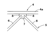
図7は、建築物の外周に沿うように配置された複数の柱(2)のうち、建築物の角部以外に位置する部分、即ち角部を結ぶ辺部(図4の円イで示す部分)における柱(2)と梁(3b)の接合構造を示す図であって、(a)は平面図、(b)はA方向矢視図である。
建築物の辺部に位置する柱(2)は、長方形の隣り合う2つの角を45度方向に切り欠いた六角形状の横断面を有する管体(鋼管)からなり、この管体の2つの切欠面に夫々短尺のH型鋼からなる接合部材(43)の一端部が溶接されている。尚、図中の黒塗り部分が溶接部分である。そして、接合部材(43)の他端部に、梁(3b)の端部がジョイントプレート(41)を介して接続されている。
尚、柱(2)の横断面形状は、図示例では六角形状のものが示されているが、五角形状(ホームベース形)であってもよい。
FIG. 7 shows a part located outside the corner of the building among the plurality of pillars (2) arranged along the outer periphery of the building, that is, a side connecting the corners (indicated by a circle in FIG. 4). It is a figure which shows the joining structure of the pillar (2) and beam (3b) in a part, Comprising: (a) is a top view, (b) is an A direction arrow directional view.
The column (2) located on the side of the building is composed of a tubular body (steel pipe) having a hexagonal cross section obtained by cutting out two adjacent corners of a rectangle in a 45 degree direction. One end of a joining member (43) made of a short H-shaped steel is welded to the cut surface. In addition, the black coating part in a figure is a welding part. Then, the end of the beam (3b) is connected to the other end of the joining member (43) via a joint plate (41).
In addition, although the cross-sectional shape of the column (2) is a hexagonal shape in the illustrated example, it may be a pentagonal shape (home base shape).
梁(3b)同士は、互いに直交するように斜め格子状に配置されている(図4参照)。
図8は梁(3b)同士の直交部分の構造を示す図であって、(a)はラチスが無い状態の図、(b)はラチスがある状態の図である。
図示のように、互いに直交する2本の梁(3b)のうち、一方の梁の両側面には当該梁に対して直角をなす短尺のH型鋼からなる接合部材(43)の一端部が溶接されている。尚、図中の黒塗り部分が溶接部分である。そして、接合部材(43)の他端部には、一方の梁に直交する他方の梁の端部がジョイントプレート(41)を介して接続されている。
梁(3b)同士が直交する部分において、梁の上下フランジ間を接続するように補強プレート(スチフナー)(42)が接合されている。
具体的には、一方の梁には、当該梁の上下フランジ間を接続する補強プレート(42)が、その面が他方の梁のフランジ側縁の延長線上にあるように配置されている。
また、他方の梁及び接合部材(43)にも、上下フランジ間を接続するように補強プレート(42)が夫々接合されており、これらの補強プレート(42)はジョイントプレート(41)を挟むように配置されている。
The beams (3b) are arranged in an oblique lattice shape so as to be orthogonal to each other (see FIG. 4).
FIG. 8 is a diagram showing the structure of the orthogonal portion between the beams (3b), in which (a) is a diagram in the absence of lattice, and (b) is a diagram in the presence of lattice.
As shown in the figure, one end portion of a short joining member (43) made of a short H-shaped steel perpendicular to the beam is welded to both side surfaces of two beams (3b) orthogonal to each other. Has been. In addition, the black coating part in a figure is a welding part. The other end of the joining member (43) is connected to the end of the other beam orthogonal to the first beam via the joint plate (41).
A reinforcing plate (stiffener) (42) is joined so as to connect the upper and lower flanges of the beam at a portion where the beams (3b) are orthogonal to each other.
Specifically, a reinforcing plate (42) that connects between the upper and lower flanges of the beam is arranged on one beam so that the surface thereof is on the extension line of the flange side edge of the other beam.
Further, the reinforcing plate (42) is joined to the other beam and the joining member (43) so as to connect the upper and lower flanges, and these reinforcing plates (42) sandwich the joint plate (41). Is arranged.
互いに直交する梁(3b)は夫々上下フランジ間が波形状のラチス(5)で接続された合成梁から構成されている。尚、図8ではラチス(5)は梁同士の交差部分の手前側にのみ描かれ、奥側においては省略されている。
これら梁(3b)の上下フランジ間に接合されたラチス(5)は、当該梁の長さ方向に沿って延びており、その端部は補強プレート(42)の手前に位置している。すなわち、接合部分の構造上、ラチス(5)は、互いに直交する梁(3b)の接合部分まで至るように設けることが困難であるため、接合部分の手前までの部分のみに設けられている。
その結果、接合部分の近傍では梁に対してラチスによる強度補強がなされていない状態となる。そのため、本発明では補強プレート(42)を設けてラチスが無い部分の強度を補強することにより、梁同士の接合部分の強度を確保している。
The beams (3b) orthogonal to each other are composed of composite beams in which the upper and lower flanges are connected by a wave-shaped lattice (5). In FIG. 8, the lattice (5) is drawn only on the front side of the intersection of the beams and is omitted on the back side.
The lattice (5) joined between the upper and lower flanges of these beams (3b) extends along the length direction of the beam, and the end thereof is positioned in front of the reinforcing plate (42). That is, because of the structure of the joint portion, it is difficult to provide the lattice (5) so as to reach the joint portion of the beams (3b) orthogonal to each other, and therefore, the lattice (5) is provided only in the portion before the joint portion.
As a result, in the vicinity of the joint portion, the beam is not reinforced by the lattice. Therefore, in the present invention, a reinforcing plate (42) is provided to reinforce the strength of the portion without the lattice, thereby ensuring the strength of the joint portion between the beams.
図9は本発明に係る大スパン構造建築物における基礎の変更例である。
図9(a)は、基礎(1)を建築物の外周に沿って(外周を囲うように)配置し、基礎同士を地中梁で連結することなく各基礎を独立させた例である。
図9(b)は、基礎(1)の建築物の外周の一部に沿って(外周の互いに平行な二辺のみに沿って)配置し、基礎同士を地中梁(9)で連結させた例である。
図9(c)は、建築物の外周の一部に沿って(外周の互いに平行な二辺のみに沿って)配置し、基礎同士を地中梁で連結することなく各基礎を独立させた例である。
上記の例では、基礎及び柱が、建築物の外周に沿う部分の角部と、隣り合う角部間を結ぶ辺部の両方に設けられる。
図9(d)は、基礎(1)を建築物の外周に沿う部分の角部にのみ配置し、基礎同士を地中梁で連結することなく各基礎を独立させた例である。この例では、基礎及び柱が、建築物の外周に沿う部分の角部のみに設けられる。
尚、図9の例において、基礎より上部の構成は柱の本数及び位置を除いて図4と同様である。
図1と図9の基礎のうち、いずれを使用するかは、地盤の状況、構造計算により決定する。
FIG. 9 is a modification example of the foundation in the large span structure building according to the present invention.
FIG. 9A is an example in which the foundation (1) is arranged along the outer periphery of the building (so as to surround the outer periphery), and the foundations are made independent without connecting the foundations with underground beams.
Fig. 9 (b) is arranged along a part of the outer periphery of the building of the foundation (1) (along only two sides parallel to each other on the outer periphery), and the foundations are connected by underground beams (9). This is an example.
Fig. 9 (c) is arranged along a part of the outer periphery of the building (only along two parallel sides of the outer periphery), and the foundations are made independent without connecting the foundations with underground beams. It is an example.
In said example, a foundation and a pillar are provided in both the corner | angular part of the part which follows the outer periphery of a building, and the edge part which connects between adjacent corner | angular parts.
FIG. 9D is an example in which the foundation (1) is disposed only at the corners along the outer periphery of the building, and the foundations are made independent without connecting the foundations with underground beams. In this example, the foundation and the pillar are provided only at the corners along the outer periphery of the building.
In the example of FIG. 9, the configuration above the foundation is the same as that of FIG. 4 except for the number and position of the columns.
Which of the foundations in FIGS. 1 and 9 is used is determined by the ground condition and the structure calculation.
図10は、基礎(1)を建築物の外周に沿う部分の角部にのみ配置した場合(図9(d)参照)における梁同士の接合部分を示す図である。具体的には、角部に位置する柱同士を繋ぐ梁(3a)と、斜め方向に延びる梁(3b)との接合部分を示す図であって、(a)は平面図、(b)はA方向矢視図(ラチスを省略したもの)、(c)はA方向矢視図(ラチスを表示したもの)である。
図示のように、梁(3b)は、梁(3a)に対して平面視にて斜め45度の方向に延びるように接合されている。この例では、図7に示した例とは異なり接合部分に柱が無いため、梁(3a)と梁(3b)とは直接溶接されている。
FIG. 10 is a diagram showing a joint portion between beams when the foundation (1) is arranged only at the corner portion along the outer periphery of the building (see FIG. 9D). Specifically, it is a diagram showing a joint portion between a beam (3a) connecting columns located at corners and a beam (3b) extending in an oblique direction, (a) is a plan view, and (b) is a plan view. A direction arrow view (thing which omitted lattice), (c) is an A direction arrow view (what displayed lattice).
As illustrated, the beam (3b) is joined to the beam (3a) so as to extend in a direction of 45 degrees obliquely in plan view. In this example, unlike the example shown in FIG. 7, there is no column at the joint, so the beam (3a) and the beam (3b) are directly welded.
梁(3b)は、端部が長さ方向に対して斜め45度に切断されており、この切断面において梁(3a)の側面と溶接されている。尚、図中の黒塗り部分が溶接部分である。
梁(3a)の梁(3b)側の側面には、上下フランジ間を接続するように補強プレート(スチフナー)(42)が接合されている。当該補強プレート(42)は、その面が梁(3b)の外方側(梁(3a)と鋭角をなす側)におけるフランジ側縁に対応する位置に配置されている。
梁(3b)にも、上下フランジ間を接続するように補強プレート(スチフナー)(42)が接合されている。この補強プレート(42)は梁(3a)との接合境界部分(溶接部分)に沿って配置されている。
これにより、梁(3a)と梁(3b)に設けられた補強プレート(42)は平面視においてL字形の配置となっている。
The end of the beam (3b) is cut at an angle of 45 degrees with respect to the length direction, and the side surface of the beam (3a) is welded to the cut surface. In addition, the black coating part in a figure is a welding part.
A reinforcing plate (stiffener) (42) is joined to the side surface of the beam (3a) on the beam (3b) side so as to connect the upper and lower flanges. The reinforcing plate (42) is disposed at a position corresponding to the flange side edge on the outer side of the beam (3b) (the side forming an acute angle with the beam (3a)).
A reinforcing plate (stiffener) (42) is also joined to the beam (3b) so as to connect the upper and lower flanges. The reinforcing plate (42) is disposed along the boundary portion (welded portion) with the beam (3a).
Thereby, the reinforcement plate (42) provided in the beam (3a) and the beam (3b) has an L-shaped arrangement in plan view.
梁(3a)と梁(3b)は、夫々上下フランジ間が波形状のラチス(5)で接続された合成梁から構成されている。
これら梁(3a)(3b)の上下フランジ間に接合されたラチス(5)は、夫々梁の長さ方向に沿って延びており、その端部は補強プレート(42)の手前に位置している。すなわち、接合部分の構造上、ラチス(5)は、梁(3a)と梁(3b)の接合部分まで至るように設けることが困難であるため、接合部分の手前までの部分のみに設けられている。
その結果、接合部分の近傍では梁に対してラチスによる強度補強がなされていない状態となる。そのため、本発明では補強プレート(42)を設けてラチスが無い部分の強度を補強することにより、梁同士の接合部分の強度を確保している。
The beam (3a) and the beam (3b) are each composed of a composite beam in which the upper and lower flanges are connected by a wavy lattice (5).
The lattice (5) joined between the upper and lower flanges of the beams (3a) and (3b) extends along the length direction of each beam, and its end is located in front of the reinforcing plate (42). Yes. That is, because of the structure of the joint portion, it is difficult to provide the lattice (5) so as to reach the joint portion between the beam (3a) and the beam (3b). Therefore, the lattice (5) is provided only in the portion before the joint portion. Yes.
As a result, in the vicinity of the joint portion, the beam is not reinforced by the lattice. Therefore, in the present invention, a reinforcing plate (42) is provided to reinforce the strength of the portion without the lattice, thereby ensuring the strength of the joint portion between the beams.
以下、各基礎を独立させた場合(図9(a)(c)(d)の場合)における基礎構造について説明する。
図11及び図12は各基礎を独立させた場合における基礎構造の第一実施形態を示す図であって、図11は分解斜視図、図12(a)は平面図、(b)は正面図、(c)は底面図、(d)は側面図である。
この基礎構造は、鋼管柱等からなる建築物の柱(2)を、フーチング、地中梁、基礎スラブ等のコンクリート構造体を介することなく、地盤の支持層に達する深さまで打ち込まれた鋼管杭等の杭(10)からなる基礎(1)と接続してなるものである。
Hereinafter, the foundation structure when each foundation is made independent (in the case of FIGS. 9A, 9C, and 9D) will be described.
11 and 12 are views showing a first embodiment of a foundation structure in which each foundation is made independent. FIG. 11 is an exploded perspective view, FIG. 12A is a plan view, and FIG. , (C) is a bottom view, and (d) is a side view.
This foundation structure is a steel pipe pile that is driven to the depth that reaches the support layer of the ground without going through concrete structures such as footings, underground beams, foundation slabs, etc. It connects with the foundation (1) which consists of piles (10), such as.
柱(2)の下端部には、該下端面よりも一回り大きい外形を有する鋼板等からなるベースプレート(17)が溶接等の固着手段を用いて接合されている。
杭(10)の杭頭には、該杭頭面により一回り大きい外形を有する鋼板等からなる杭頭プレート(11)が溶接等の固着手段を用いて接合されている。
ベースプレート(17)は、中間プレート(12)を介して杭頭プレート(11)と接合されている。
A base plate (17) made of a steel plate or the like having an outer shape slightly larger than the lower end surface is joined to the lower end portion of the column (2) using a fixing means such as welding.
A pile head plate (11) made of a steel plate or the like having an outer shape that is slightly larger than the pile head surface is joined to the pile head of the pile (10) by using a fixing means such as welding.
The base plate (17) is joined to the pile head plate (11) via the intermediate plate (12).
ベースプレート(17)と中間プレート(12)は、ベースプレート(17)の下面を中間プレート(12)の上面に密接させた状態で、ベースプレート(17)の上面から柱(2)の周囲に沿って複数本のアンカーボルト(18)(図12参照、図11では省略)を下方に打ち込んで中間プレート(12)を挿通させることにより固定されている。
杭頭プレート(11)と中間プレート(12)は、杭頭プレート(11)の上面を中間プレート(12)の下面に密接させた状態で、両者を溶接することにより固定されている。これにより、ベースプレート(17)と杭頭プレート(11)とは、中間プレート(12)を介して接合されている。
The base plate (17) and the intermediate plate (12) include a plurality of base plates (17) extending from the upper surface of the base plate (17) to the periphery of the column (2) with the lower surface of the base plate (17) being in close contact with the upper surface of the intermediate plate (12). The anchor bolt (18) (see FIG. 12, not shown in FIG. 11) is driven downward and the intermediate plate (12) is inserted to fix the bolt.
The pile head plate (11) and the intermediate plate (12) are fixed by welding the two in a state where the upper surface of the pile head plate (11) is in close contact with the lower surface of the intermediate plate (12). Thereby, the base plate (17) and the pile head plate (11) are joined via the intermediate plate (12).
中間プレート(12)は、H型鋼等からなる同じ長さの複数本の鋼材(13)からなり、これら複数本の鋼材を断面I字状となる向きで互いに平行に並べ、並べられた鋼材を接合することでプレート状とされたものである。
複数本の鋼材(13)を接合する方法としては、単に鋼材間を溶接するのみでもよいが、更に図示するように表面に鋼材(13)の長さ方向と直角方向に補強プレート(14)を配置し、この補強プレート(14)を複数本の鋼材(13)夫々と溶接する方法を用いると、高い接合強度を得ることができるため好ましい。
このようにして得られた中間プレート(12)の幅方向(鋼材(13)の幅方向)の両辺には、幅方向端部の強度を補強するために、鋼板等からなる複数本の補強リブ(15)が縦方向に設けられる。
The intermediate plate (12) is composed of a plurality of steel materials (13) of the same length made of H-shaped steel, etc., and these steel materials are arranged in parallel with each other in an I-shaped cross section, and the aligned steel materials are arranged. It is made into a plate shape by joining.
As a method of joining a plurality of steel materials (13), the steel materials may be simply welded, but a reinforcing plate (14) is provided on the surface in a direction perpendicular to the length direction of the steel materials (13) as shown in the figure. It is preferable to use a method of arranging and welding the reinforcing plate (14) to each of the plurality of steel materials (13) because high joint strength can be obtained.
In order to reinforce the strength of the end in the width direction on both sides of the width direction of the intermediate plate (12) thus obtained (the width direction of the steel material (13)), a plurality of reinforcing ribs made of steel plates or the like are provided. (15) is provided in the vertical direction.
中間プレート(12)の大きさや形状は、柱や杭の太さ並びに杭の本数に応じて適宜設定することができ、鋼材(13)の本数や長さを変えることで、所要面積の中間プレートを現場にて容易に得ることができる。
但し、本発明において用いられる中間プレート(12)の形態はこれに限定されず、例えば1枚板のプレートを用いてもよいが、図示のような中間プレート(12)は1枚板のプレートに比べて高い剛性や曲げ強度を有するため好適に用いられる。
The size and shape of the intermediate plate (12) can be set as appropriate according to the thickness of the pillars and piles and the number of piles. By changing the number and length of the steel materials (13), the intermediate plate of the required area Can be easily obtained on site.
However, the form of the intermediate plate (12) used in the present invention is not limited to this. For example, a single plate may be used, but the intermediate plate (12) as illustrated is a single plate. Compared with high rigidity and bending strength, it is preferably used.
図13は第一実施形態の基礎構造の変形例を示す図であって、(a)〜(d)図において上方に底面図、下方に正面図が夫々示されている。
(a)図は1本の柱(2)に対して1本の杭(10)を接続したもの、(b)図は1本の柱(2)に対して2本の杭(10)を接続したもの、(c)図は1本の柱(2)に対して3本の杭(10)を接続したもの、(d)図は1本の柱(2)に対して4本の杭(10)を接続したもの、である。
このように、本発明に係る基礎構造においては、1本の柱(2)に対して1本又は複数本の杭(10)を接続することができ、1本の柱に接続される杭の本数は、地盤の強度が弱い場合や支えられる建築物の重量が大きい場合等には増やされる。
FIG. 13 is a view showing a modification of the basic structure of the first embodiment. In FIGS. 13A to 13D, a bottom view is shown above, and a front view is shown below.
(A) The figure shows one pile (10) connected to one pillar (2), (b) The figure shows two piles (10) for one pillar (2). Connected, (c) The figure shows three piles (10) connected to one pillar (2), (d) The figure shows four piles for one pillar (2) (10) is connected.
Thus, in the foundation structure according to the present invention, one or a plurality of piles (10) can be connected to one pillar (2), and the pile connected to one pillar The number is increased when the strength of the ground is weak or the weight of the supported building is large.
本発明に係る基礎構造において、当該基礎構造によって支持される建築物が中高層建築物である場合には、図13に示すように、ベースプレート(17)と中間プレート(12)の間に免震機構(16)を介在させることが好ましい。
免震機構(16)としては、免震ゴムや免震ダンパー等の建築物において用いられている公知の免震機構を利用することができる。
In the foundation structure according to the present invention, when the building supported by the foundation structure is a medium-high-rise building, as shown in FIG. 13, the seismic isolation mechanism is provided between the base plate (17) and the intermediate plate (12). It is preferable to interpose (16).
As the seismic isolation mechanism (16), a known seismic isolation mechanism used in a building such as a seismic isolation rubber or a seismic isolation damper can be used.
上記構成からなる基礎構造は、以下の工程により得ることができる。
先ず、杭(10)を地盤の支持層に達する深さまで打設して、設計位置の高さで杭頭部を水平に調整した後、杭頭に杭頭プレート(11)を溶接等により接合し、次いで、複数本の鋼材(13)を組み合わせて得られた中間プレート(12)を杭頭プレート(11)の上部に設置し、補強プレート(14)を上面に溶接して中間プレート(12)を補強する。
そして、中間プレート(12)の上面に、柱(2)の下端部に対して一体に固定されたベースプレート(17)をアンカーボルト等により固定することにより、杭(10)の上部に柱(2)が一体に接合された基礎構造が得られる。
The basic structure having the above configuration can be obtained by the following steps.
First, the pile (10) is driven to a depth that reaches the ground support layer, the pile head is adjusted horizontally at the height of the design position, and then the pile head plate (11) is joined to the pile head by welding or the like. Then, the intermediate plate (12) obtained by combining a plurality of steel materials (13) is installed on the top of the pile head plate (11), and the reinforcing plate (14) is welded to the upper surface to connect the intermediate plate (12 ).
And the base plate (17) fixed integrally with the lower end part of the column (2) is fixed to the upper surface of the intermediate plate (12) with an anchor bolt or the like, so that the column (2 ) Can be obtained.
このようにして得られる基礎構造は、柱(2)を地盤に支持層まで打ち込んだ杭(10)からなる基礎(1)と接続した構造であるため、基礎(1)上に増築される建築物の不同沈下を防いで充分な耐震性を付与することができる。
そのため、新たな基礎同士を連結するための地中梁が不要となり、またフーチング、地中梁、基礎スラブ等のコンクリート構造体を介することなく柱と杭とを接続するので、従来の杭基礎を用いる場合に比べて施工期間を大幅に短縮することができる。
Since the foundation structure obtained in this way is a structure connected to the foundation (1) consisting of the pile (10) driven into the ground up to the support layer, the building to be extended on the foundation (1) Sufficient earthquake resistance can be given by preventing uneven settlement of objects.
This eliminates the need for underground beams to connect new foundations, and connects columns and piles without interposing concrete structures such as footings, underground beams and foundation slabs. The construction period can be greatly shortened compared to the case of using.
図14は、各基礎を独立させた場合における基礎構造の第二実施形態である。
第二実施形態の基礎構造は、基礎(1)が地中に打ち込まれた杭(20)からなり、杭(20)の断面よりも大きな中空断面を有する管状カバー(21)がその下方部を杭(20)の上端部に被せて立設されている。そして、管状カバー(21)の上方部に柱(2)の下端部が配置されるとともに、管状カバー(21)の内部にコンクリート又は高強度樹脂モルタル(22)が充填されている。
FIG. 14 shows a second embodiment of the foundation structure when each foundation is made independent.
The foundation structure of 2nd embodiment consists of the pile (20) by which the foundation (1) was driven in the ground, and the tubular cover (21) which has a hollow cross section larger than the cross section of a pile (20) has the lower part. It is erected over the upper end of the pile (20). And while the lower end part of the pillar (2) is arrange | positioned at the upper part of the tubular cover (21), the inside of the tubular cover (21) is filled with concrete or high-strength resin mortar (22).
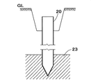
以下、第二実施形態の基礎構造の構築方法について説明する。
先ず、図15に示すように、杭(20)を地中の支持層(23)に達する深さまで打ち込む。この杭(20)は鋼管杭が好適に用いられるが、場所打ち杭を用いることも可能である。
杭(20)が鋼管杭である場合には、図16に示すように、打設された杭(20)の内部にコンクリート(22)を充填する。
Hereinafter, the construction method of the basic structure of the second embodiment will be described.
First, as shown in FIG. 15, the pile (20) is driven to a depth that reaches the underground support layer (23). As this pile (20), a steel pipe pile is preferably used, but a cast-in-place pile can also be used.
When the pile (20) is a steel pipe pile, as shown in FIG. 16, concrete (22) is filled into the placed pile (20).
それから、図17に示すように、杭(20)の断面よりも大きな中空断面を有する管状カバー(21)を杭(20)の上端部に被せるように立設する。このとき、図示の如く、杭(20)の上端部周囲の土を予め除去しておき、この除去部分に管状カバー(21)を入れて立設させるようにするとよい。
管状カバー(21)としては、杭(20)よりも大きい肉厚(例えば3〜5倍程度)を有する四角鋼管が好適に用いられる。
杭(20)の上端部は地面よりもやや下方位置となるようにし、管状カバー(21)はその下端部が杭(20)の上端部から所定深さ(例えば杭の外径の1〜3倍程度)まで達するように地中に打ち込み、その後で管状カバー(21)の周囲に土を埋め戻す(図18参照)。このとき、管状カバー(21)の上端部は地面からやや露出するようにするとよい。
Then, as shown in FIG. 17, a tubular cover (21) having a hollow cross section larger than the cross section of the pile (20) is erected so as to cover the upper end portion of the pile (20). At this time, as shown in the drawing, the soil around the upper end of the pile (20) may be removed in advance, and the tubular cover (21) may be put in the removed portion to be erected.
As the tubular cover (21), a square steel pipe having a larger wall thickness (for example, about 3 to 5 times) than the pile (20) is preferably used.
The upper end of the pile (20) is positioned slightly below the ground, and the lower end of the tubular cover (21) has a predetermined depth from the upper end of the pile (20) (for example, 1 to 3 of the outer diameter of the pile). It is driven into the ground so as to reach about twice, and then the soil is backfilled around the tubular cover (21) (see FIG. 18). At this time, the upper end of the tubular cover (21) may be slightly exposed from the ground.
次いで、図19に示すように、管状カバー(21)の内部にベースパック等のアンカー(24)を設置し、管状カバー(21)内にコンクリート(22)を打設してアンカー(24)を管状カバー(21)内に固定する。このとき、アンカー(24)の上端部は管状カバー(21)の上端面よりも下方位置となるようにし、コンクリート(22)の上面はアンカー(24)の上端部よりも下方位置となるようにするとよい。 Next, as shown in FIG. 19, an anchor (24) such as a base pack is placed inside the tubular cover (21), and concrete (22) is placed in the tubular cover (21) to anchor the anchor (24) into the tubular shape. Secure in the cover (21). At this time, the upper end of the anchor (24) is positioned below the upper end surface of the tubular cover (21), and the upper surface of the concrete (22) is positioned below the upper end of the anchor (24). Good.
そして、アンカー(24)の上部に、スタッドジベル(25)とベースプレート(26)とが設けられた柱(2)を建てて(図20参照)、アンカー(24)と柱(2)の下端部に設けられたベースプレート(26)とをボルト止めにより固定した後、管状カバー(21)内の上端部に更に別の管状カバー(21)を設置して柱(2)の下方部周囲を覆い、上部と下部の管状カバー(21)を溶接又は補強プレートにより接合一体化する(図21参照)。
そして、上部の管状カバー(21)からコンクリート又は高強度樹脂モルタル(22)を管状カバー内全体に充填することにより、杭(20)と柱(2)が強固に一体化固定される(図14参照)。
And the pillar (2) provided with the stud gibber (25) and the base plate (26) is built on the upper part of the anchor (24) (see FIG. 20), and the lower ends of the anchor (24) and the pillar (2). After fixing the base plate (26) provided to the base plate by bolting, another tubular cover (21) is installed at the upper end of the tubular cover (21) to cover the lower part of the pillar (2), The upper and lower tubular covers (21) are joined and integrated by welding or a reinforcing plate (see FIG. 21).
Then, by filling concrete or high-strength resin mortar (22) in the entire tubular cover from the upper tubular cover (21), the pile (20) and the pillar (2) are firmly integrated and fixed (FIG. 14). reference).
第一実施形態及び第二実施形態の基礎構造は、柱(2)が支持層まで打ち込まれた杭(10)(20)と一体化されて立設されるので、高強度の合成梁(3)を用いることと相俟って、建築物全体の耐震性を向上させることができる。 Since the foundation structure of 1st embodiment and 2nd embodiment is united with the pile (10) (20) by which the pillar (2) was driven to the support layer, and is standingly arranged, a high strength synthetic beam (3 ) Can be used to improve the earthquake resistance of the entire building.
尚、第二実施形態の基礎構造において、構造計算上、基礎梁を入れた方がよい場合には、鉄骨又は鉄骨コンクリートからなる基礎梁を設けることができる。
図22は基礎梁(27)を設けた状態を示す図であって、図示の如く、角形管状カバー(21)の側面に基礎梁(27)が固定され、これにより隣り合う角形管状カバー(21)同士、即ち隣り合う柱(2)同士が基礎梁(27)により接続される。尚、この基礎梁(27)は、実線で示すように地上に設けてもよいし、破線で示すように地中梁としてもよい。
In addition, in the foundation structure of the second embodiment, when it is better to insert a foundation beam for structural calculation, a foundation beam made of steel or steel concrete can be provided.
FIG. 22 is a view showing a state in which the foundation beam (27) is provided. As shown in the drawing, the foundation beam (27) is fixed to the side surface of the rectangular tubular cover (21), and thereby the adjacent rectangular tubular cover (21). ), That is, adjacent columns (2) are connected by a foundation beam (27). The foundation beam (27) may be provided on the ground as indicated by a solid line, or may be an underground beam as indicated by a broken line.
本発明では、梁(3)としてH型鋼の上下フランジ間を波形状のラチスで接続した合成梁を用いることに加えて、建築物の外周に沿う部分に設置された基礎(1)の構造として、上記した第一及び第二実施形態の基礎構造を用いることにより、建築物の中央部において基礎、地中梁、柱が設けられていない構造を採用した場合においても、高い耐震性を有する建築物を得ることができる。 In the present invention, in addition to using a composite beam in which the upper and lower flanges of the H-shaped steel are connected with a wave-shaped lattice as the beam (3), the structure of the foundation (1) installed in the portion along the outer periphery of the building By using the foundation structures of the first and second embodiments described above, even when a structure in which the foundation, underground beam, and pillar are not provided in the central part of the building, the building has high earthquake resistance. You can get things.
本発明は、広い内部空間を有する建築物を構築するために好適に利用することができる。 The present invention can be suitably used to construct a building having a wide internal space.
1 基礎
2 柱
3 梁
3a 隣り合う柱同士の間に架設された梁
3b 斜め方向に延びる梁
4 H型鋼
4a フランジ
5 ラチス
6 ラチス材
7 隣り合うラチス材の端面同士の隙間
8 ラチス材とH型鋼のフランジとの対向面同士の隙間
42 補強プレート(スチフナー)
DESCRIPTION OF
Claims (9)
前記基礎は建築物の外周に沿う部分及び/又はその内側近傍部分にのみ設置され、
前記梁がH型鋼の上下フランジ間を波形状のラチスで接続した合成梁からなり、
該合成梁が、前記柱間に架設された梁に対して平面視にて斜め方向に延びるように架設されていることを特徴とする大スパン構造建築物。 A building in which pillars are erected on top of a plurality of foundations, and beams are erected between the pillars,
The foundation is installed only in the part along the outer periphery of the building and / or the inner vicinity thereof,
The beam comprises a composite beam in which the upper and lower flanges of the H-shaped steel are connected with a wave-shaped lattice,
A large-span structure building, wherein the composite beam is constructed so as to extend obliquely in plan view with respect to the beam constructed between the columns.
前記ラチスを構成するラチス材は、隣り合うラチス材の先端面同士が略平行になるように且つ隙間を有するように配置されており、
前記溶接が、各ラチス材の端部において、該ラチス材と前記フランジとの対向面同士の隙間及び前記先端面同士の間の隙間を埋めるようになされていることを特徴とする請求項1記載の大スパン構造建築物。 The composite beam is formed by welding a flange of H-shaped steel and a lattice,
The lattice material constituting the lattice is arranged so that the front end surfaces of adjacent lattice materials are substantially parallel to each other and have a gap,
2. The welding is performed so as to fill a gap between opposing surfaces of the lattice material and the flange and a gap between the front end surfaces at an end portion of each lattice material. Large span structure building.
Priority Applications (1)
| Application Number | Priority Date | Filing Date | Title |
|---|---|---|---|
| JP2007195009A JP2009030319A (en) | 2007-07-26 | 2007-07-26 | Long-span structure building |
Applications Claiming Priority (1)
| Application Number | Priority Date | Filing Date | Title |
|---|---|---|---|
| JP2007195009A JP2009030319A (en) | 2007-07-26 | 2007-07-26 | Long-span structure building |
Publications (1)
| Publication Number | Publication Date |
|---|---|
| JP2009030319A true JP2009030319A (en) | 2009-02-12 |
Family
ID=40401120
Family Applications (1)
| Application Number | Title | Priority Date | Filing Date |
|---|---|---|---|
| JP2007195009A Pending JP2009030319A (en) | 2007-07-26 | 2007-07-26 | Long-span structure building |
Country Status (1)
| Country | Link |
|---|---|
| JP (1) | JP2009030319A (en) |
Cited By (5)
| Publication number | Priority date | Publication date | Assignee | Title |
|---|---|---|---|---|
| CN102704569A (en) * | 2012-05-25 | 2012-10-03 | 湖南大学 | Multilayer large-span assembling integral type space steel grid building structure and manufacturing method |
| CN103291004A (en) * | 2013-06-27 | 2013-09-11 | 贵州大学 | Assembly type rectangular plane roof and manufacturing method thereof |
| CN105672478A (en) * | 2016-03-15 | 2016-06-15 | 叶长青 | Roof structure of long-span building |
| WO2023123321A1 (en) * | 2021-12-31 | 2023-07-06 | 海南大学 | Large-span prefabricated structure |
| JP7307418B1 (en) | 2022-04-15 | 2023-07-12 | 穰二 林 | H-shaped steel |
-
2007
- 2007-07-26 JP JP2007195009A patent/JP2009030319A/en active Pending
Cited By (9)
| Publication number | Priority date | Publication date | Assignee | Title |
|---|---|---|---|---|
| CN102704569A (en) * | 2012-05-25 | 2012-10-03 | 湖南大学 | Multilayer large-span assembling integral type space steel grid building structure and manufacturing method |
| CN103291004A (en) * | 2013-06-27 | 2013-09-11 | 贵州大学 | Assembly type rectangular plane roof and manufacturing method thereof |
| CN103291004B (en) * | 2013-06-27 | 2016-08-10 | 贵州大学 | A kind of assembled rectangular plane roof and preparation method thereof |
| CN105672478A (en) * | 2016-03-15 | 2016-06-15 | 叶长青 | Roof structure of long-span building |
| CN107700843A (en) * | 2016-03-15 | 2018-02-16 | 叶长青 | The construction method of long span building roof structure |
| CN105672478B (en) * | 2016-03-15 | 2018-02-23 | 叶长青 | The roof structure of long span building |
| CN107700843B (en) * | 2016-03-15 | 2020-05-01 | 叶长青 | Construction method of large-span building roof structure |
| WO2023123321A1 (en) * | 2021-12-31 | 2023-07-06 | 海南大学 | Large-span prefabricated structure |
| JP7307418B1 (en) | 2022-04-15 | 2023-07-12 | 穰二 林 | H-shaped steel |
Similar Documents
| Publication | Publication Date | Title |
|---|---|---|
| KR20180109766A (en) | E-z connecting structure for beam and column wherein the end-moment and bending resistibility are reinforced | |
| JP2009030319A (en) | Long-span structure building | |
| JP2008075425A (en) | Joining structure of pile and column | |
| JP2009013616A (en) | Long span structure building | |
| JP7449685B2 (en) | Precast concrete shear wall joint structure | |
| JP6143068B2 (en) | Underground structure of building | |
| JP4550534B2 (en) | Building basic structure | |
| JP4649283B2 (en) | Columnar structure, pier or foundation pile using shape steel, and manufacturing method thereof | |
| JP6704801B2 (en) | Rebuilding building with existing underground outer wall | |
| JP2009019362A (en) | Structure for joining pile and column | |
| JP3172819B2 (en) | Steel reinforced concrete continuous basement wall | |
| JPH11343667A (en) | Structure for fixing column base with underground beam made of reinforced concrete | |
| JP6877612B2 (en) | Rebuilding building with existing underground outer wall | |
| KR102625510B1 (en) | Joint CFT Column and Wide Hybrid Beam | |
| JP2007039995A (en) | Seismically retrofitting frame for existing building | |
| JP2019011675A (en) | Composite structure | |
| JP7155488B2 (en) | Structural Seismic Reinforcement Structure | |
| KR102414124B1 (en) | Multi-web Reinforcing Beam, Pile using such Reinforcing Beam, Wall Structure using such Pile, and Constructing Method of such Wall Structure | |
| JP7451444B2 (en) | Foundation structure and construction method of foundation structure | |
| JP4220938B2 (en) | Reinforcement structure of existing building | |
| JPH05156654A (en) | Top-down construction method | |
| JP7300355B2 (en) | Buildings with openings | |
| JP4733496B2 (en) | Seismic retrofit structure | |
| JP3082059B2 (en) | Steel reinforced concrete continuous basement wall with built-in columns and beams | |
| TWI493092B (en) | Joint structure of concrete filled steel tubular (cft) column |