JP2009021402A - Solar battery module and installing method thereof - Google Patents
Solar battery module and installing method thereof Download PDFInfo
- Publication number
- JP2009021402A JP2009021402A JP2007182933A JP2007182933A JP2009021402A JP 2009021402 A JP2009021402 A JP 2009021402A JP 2007182933 A JP2007182933 A JP 2007182933A JP 2007182933 A JP2007182933 A JP 2007182933A JP 2009021402 A JP2009021402 A JP 2009021402A
- Authority
- JP
- Japan
- Prior art keywords
- solar cell
- cell module
- solar battery
- solar
- curing sheet
- Prior art date
- Legal status (The legal status is an assumption and is not a legal conclusion. Google has not performed a legal analysis and makes no representation as to the accuracy of the status listed.)
- Pending
Links
Images


Classifications
-
- Y—GENERAL TAGGING OF NEW TECHNOLOGICAL DEVELOPMENTS; GENERAL TAGGING OF CROSS-SECTIONAL TECHNOLOGIES SPANNING OVER SEVERAL SECTIONS OF THE IPC; TECHNICAL SUBJECTS COVERED BY FORMER USPC CROSS-REFERENCE ART COLLECTIONS [XRACs] AND DIGESTS
- Y02—TECHNOLOGIES OR APPLICATIONS FOR MITIGATION OR ADAPTATION AGAINST CLIMATE CHANGE
- Y02B—CLIMATE CHANGE MITIGATION TECHNOLOGIES RELATED TO BUILDINGS, e.g. HOUSING, HOUSE APPLIANCES OR RELATED END-USER APPLICATIONS
- Y02B10/00—Integration of renewable energy sources in buildings
- Y02B10/10—Photovoltaic [PV]
-
- Y—GENERAL TAGGING OF NEW TECHNOLOGICAL DEVELOPMENTS; GENERAL TAGGING OF CROSS-SECTIONAL TECHNOLOGIES SPANNING OVER SEVERAL SECTIONS OF THE IPC; TECHNICAL SUBJECTS COVERED BY FORMER USPC CROSS-REFERENCE ART COLLECTIONS [XRACs] AND DIGESTS
- Y02—TECHNOLOGIES OR APPLICATIONS FOR MITIGATION OR ADAPTATION AGAINST CLIMATE CHANGE
- Y02E—REDUCTION OF GREENHOUSE GAS [GHG] EMISSIONS, RELATED TO ENERGY GENERATION, TRANSMISSION OR DISTRIBUTION
- Y02E10/00—Energy generation through renewable energy sources
- Y02E10/50—Photovoltaic [PV] energy
Landscapes
- Roof Covering Using Slabs Or Stiff Sheets (AREA)
- Photovoltaic Devices (AREA)
Abstract
Description
本発明は、屋根などに設置する太陽電池モジュール及びその設置方法に関する。 The present invention relates to a solar cell module installed on a roof or the like and an installation method thereof.
太陽電池発電は、環境に優しい新しいエネルギーとして注目を集め、順調に導入が進んでいる。太陽電池モジュールの構造としては、発電素子をエチレン−酢酸ビニル共重合体(EVA)などの封止材で封止し、受光面側にガラスを用いたモジュールが多く商品化されているが、重量が重いこと、曲面への設置が困難なことなどの欠点があることから、ガラスの代わりにフッ素系のフイルムを受光面側の保護材として用いた軽量でフレキシブルなモジュールも開発されている。 Solar cell power generation is attracting attention as a new environmentally friendly energy, and its introduction is progressing smoothly. As for the structure of the solar cell module, many modules using a power generation element sealed with a sealing material such as ethylene-vinyl acetate copolymer (EVA) and glass on the light receiving surface side are commercialized. In light of the fact that it is heavy and difficult to install on a curved surface, a lightweight and flexible module using a fluorine-based film as a protective material on the light receiving surface side instead of glass has been developed.
このタイプのモジュールの例としては、ガルバリウム鋼板などの金属屋根材に用いられる材料をモジュールの裏面補強材として用いた金属屋根一体型太陽電池モジュールがある。このモジュールの場合には、太陽電池としての配線作業を除けば、通常の金属屋根と全く同じ施工方法で太陽電池付き屋根を施工することができる。モジュール自体が屋根材を補強材としているために、太陽電池を搭載していない通常の金属屋根部分との調和にも優れた屋根を提供することができる。 As an example of this type of module, there is a metal roof integrated solar cell module in which a material used for a metal roof material such as a galvalume steel plate is used as a back surface reinforcing material of the module. In the case of this module, except for wiring work as a solar cell, a roof with solar cells can be constructed by the same construction method as that of a normal metal roof. Since the module itself uses the roof material as a reinforcing material, it is possible to provide a roof that is excellent in harmony with a normal metal roof portion that is not equipped with a solar cell.
受光面側の保護材としてガラスの代わりにフッ素系フイルムなどの透光性樹脂材料を用いた太陽電池モジュールの場合には、モジュール端部の曲げ加工などの製造工程や、輸送、施工作業などで太陽電池セルの表面が損傷を受ける可能性が高くなる。そこで、これらの工程において太陽電池セルの表面を保護する方法が提案されている。 In the case of a solar cell module that uses a light-transmitting resin material such as a fluorine-based film instead of glass as a protective material on the light-receiving surface side, it can be used in manufacturing processes such as bending the module edge, transportation, and construction work. The possibility that the surface of the solar battery cell is damaged is increased. Accordingly, a method for protecting the surface of the solar battery cell in these steps has been proposed.
例えば、特許文献1には、成形加工工程を含む太陽電池モジュールの製造方法において、太陽電池モジュールの受光面側に粘着性フイルム(養生シート)を貼り付けた後、係合部の加工を行い、粘着性フイルムを貼り付けたままで、太陽電池モジュールの出力特性試験や現場での施工確認試験を行う方法が開示されている。
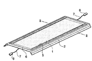
特許文献1に開示されているタイプの太陽電池モジュールを図3に示す。また、図4は、図3のIV−IV線に沿う断面図である。図3において参照符号11は太陽電池セルを示す。太陽電池セル11は、EVAのような封止材12で封止されている。封止材12の受光面側には、エチレン−テトラフルオロエチレン共重合体(ETFE)などで構成された表面保護材13が設けられている。また、太陽電池セル11の受光面の裏面側には、補強材14が配設されている。この補強材14としては、金属屋根一体型太陽電池の場合にはガルバリウム鋼板などが用いられることが多い。また、太陽電池セル11の表面保護材13上には、粘着剤層15を介して養生シート16が取り付けられている。
A solar cell module of the type disclosed in Patent Document 1 is shown in FIG. 4 is a cross-sectional view taken along line IV-IV in FIG. In FIG. 3,
実際の太陽電池モジュールの施工では、特に施工面積が大きい大型物件では、個人住宅のように数日で施工が完了せず、屋根施工後の雨仕舞やその他の付帯工事を入れると工期が1月以上に亘ってしまう場合があり、この期間の間ずっと養生シート16が太陽電池セル11の表面に取り付けられたままになることも考えられる。このように養生シート16が太陽電池セル11の受光面に貼付された状態で長期間屋外に放置されると、養生シートを剥離したときに、粘着材層15の粘着材が太陽電池セル11表面に残存し、その状態で屋外曝露を続けると、残存した粘着材にゴミなどが付着して太陽電池セル11の表面が汚れて受光性能が低下してしまう。
In actual solar cell module construction, especially in large-scale properties with a large construction area, construction will not be completed in a few days like a private house, and the construction period will be January if we add rain after roof construction and other incidental construction. In some cases, the
本発明はかかる点に鑑みてなされたものであり、太陽電池セルの表面を保護することができると共に、長期間屋外に放置されたとしても受光性能に影響を及ぼさない太陽電池モジュール及びその設置方法を提供することを目的とする。 The present invention has been made in view of the above points, and can protect the surface of the solar battery cell, and does not affect the light receiving performance even if left outdoors for a long period of time, and its installation method The purpose is to provide.
本発明の太陽電池モジュールは、素子配設領域を有する支持基材と、前記支持基材の前記素子配設領域に受光面が露出するように配設された太陽電池用発電素子と、前記支持基材の前記素子配設領域以外の領域に粘着材を介して取り付けられ、前記太陽電池用発電素子を覆うシート材と、を具備することを特徴とする。 The solar cell module of the present invention includes a support base having an element disposition region, a solar cell power generation element disposed such that a light receiving surface is exposed in the element disposition region of the support base, and the support And a sheet material that is attached to an area other than the element arrangement area of the base material via an adhesive material and covers the solar cell power generation element.
この構成によれば、シート材が、太陽電池用発電素子が存在しない領域で粘着材を介して取り付けられているので、シート材を除去した後に長時間屋外に放置したとしても、太陽電池用発電素子の表面には粘着材が残存することがないので、残存した粘着材にゴミなどが付着して太陽電池用発電素子の表面が汚れて受光性能が低下することはない。また、シート材を除去した後に、粘着材が残存したとしても太陽電池用発電素子が配置されていない領域に残存するので、太陽電池用発電素子を損傷することなく容易に粘着材を除去することができる。 According to this configuration, since the sheet material is attached via the adhesive material in the region where the solar cell power generation element does not exist, even if the sheet material is left outdoors for a long time after removing the sheet material, Since the adhesive material does not remain on the surface of the element, dust or the like adheres to the remaining adhesive material, and the surface of the power generating element for solar cells is not contaminated to reduce the light receiving performance. Moreover, even if the adhesive material remains after the sheet material is removed, it remains in the region where the solar cell power generation element is not disposed, so that the adhesive material can be easily removed without damaging the solar cell power generation element. Can do.
本発明の太陽電池モジュールにおいては、前記シート材が透明又は半透明であることが好ましい。 In the solar cell module of the present invention, the sheet material is preferably transparent or translucent.
本発明の太陽電池モジュールにおいては、前記太陽電池用発電素子の電気的検査を行うためのコネクタを具備することが好ましい。 In the solar cell module of this invention, it is preferable to comprise the connector for performing the electrical test | inspection of the said power generating element for solar cells.
本発明の太陽電池モジュールの設置方法は、複数の上記太陽電池モジュールを接続して太陽電池ストリング又は太陽電池アレイを構成する工程と、前記太陽電池ストリング又は太陽電池アレイにおける太陽電池モジュールの電気的出力検査を行う工程と、前記太陽電池モジュールから前記シート材を除去する工程と、を具備することを特徴とする。 The solar cell module installation method of the present invention includes a step of connecting a plurality of the solar cell modules to form a solar cell string or a solar cell array, and an electrical output of the solar cell module in the solar cell string or solar cell array. And a step of performing an inspection, and a step of removing the sheet material from the solar cell module.
この方法によれば、製造工程において太陽電池モジュールの表面を保護すると共に、施工時における太陽電池モジュールの損傷を防ぐこともできる。これにより、太陽電池モジュールの歩留まりを向上することができる。 According to this method, while protecting the surface of a solar cell module in a manufacturing process, damage to the solar cell module during construction can also be prevented. Thereby, the yield of a solar cell module can be improved.
本発明の太陽電池モジュールは、素子配設領域を有する支持基材と、前記支持基材の前記素子配設領域に受光面が露出するように配設された太陽電池用発電素子と、前記支持基材の前記素子配設領域以外の領域に粘着材を介して取り付けられ、前記太陽電池用発電素子を覆うシート材と、を具備するので、太陽電池セルの表面を保護することができると共に、長期間屋外に放置されたとしても受光性能に影響を及ぼさない太陽電池モジュールを実現することができる。 The solar cell module of the present invention includes a support base having an element disposition region, a solar cell power generation element disposed such that a light receiving surface is exposed in the element disposition region of the support base, and the support A sheet material that is attached to an area other than the element arrangement area of the base material via an adhesive and covers the solar cell power generation element, and can protect the surface of the solar battery cell, A solar cell module that does not affect the light receiving performance even when left outdoors for a long period of time can be realized.
以下、本発明の実施の形態について、添付図面を参照して詳細に説明する。
図1は、本発明の実施の形態に係る太陽電池モジュールの構成を示す図であり、図2は、図1のII−II線に沿う断面図である。
Hereinafter, embodiments of the present invention will be described in detail with reference to the accompanying drawings.
FIG. 1 is a diagram showing a configuration of a solar cell module according to an embodiment of the present invention, and FIG. 2 is a cross-sectional view taken along line II-II in FIG.
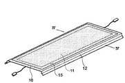
図1において参照符号1は太陽電池セルを示す。太陽電池セル1は、EVAのような封止材2で封止されている。封止材2の受光面側には、表面保護材3が設けられている。この表面保護材3を構成する材料としては、光透過性と耐候性の観点から、エチレン−テトラフルオロエチレン共重合体(ETFE)などフッ素系材料を用いることが好ましい。
In FIG. 1, reference numeral 1 indicates a solar battery cell. The solar battery cell 1 is sealed with a sealing
太陽電池セル1の受光面の裏面側には、補強材4が配設されている。この補強材4により、太陽電池セル1が支持されている。この補強材4としては、金属屋根一体型太陽電池の場合にはガルバリウム鋼板などが用いられることが多い。この補強材4の太陽電池セル1の搭載されていない部分は、必要に応じて屋根材としての折り曲げ加工が施される。 A reinforcing material 4 is disposed on the back side of the light receiving surface of the solar battery cell 1. The solar cell 1 is supported by the reinforcing material 4. In the case of a metal roof integrated solar cell, a galvalume steel plate or the like is often used as the reinforcing material 4. The portion of the reinforcing material 4 on which the solar battery cell 1 is not mounted is subjected to a bending process as a roof material as necessary.
太陽電池セル1の表面保護材3上には、粘着剤層5を介して養生シート6が取り付けられている(貼付されている)。養生シート6は、透明又は半透明であることが好ましい。また、養生シート6を構成する材料としては、ポリエチレンなどが挙げられる。また、粘着材層5を構成する粘着材の材料としては、例えば、アクリル系粘着材などが挙げられる。
On the surface protective material 3 of the solar battery cell 1, a
上記表面保護材3が厚さ約100μm以下のフッ素系材料のフィルムで構成されており、モジュール端部の曲げ加工や、輸送、施工作業などで表面に損傷を受けることが予想され、万が一これらの製造工程や運搬、施工作業などで損傷を受けると太陽電池モジュールとして十分な性能を発揮できなくなる恐れがあるので、この養生シート6により太陽電池モジュール表面の損傷を防止している。この養生シート6は、太陽電池モジュールの設置・施工において、複数の太陽電池モジュールを接続して太陽電池ストリング又は太陽電池アレイを構成し、太陽電池ストリング又は太陽電池アレイにおける太陽電池モジュールの電気的出力検査(例えば、配線の確認)を行った後に、太陽電池モジュールから除去される。
The surface protective material 3 is composed of a film of a fluorine-based material having a thickness of about 100 μm or less, and it is expected that the surface will be damaged by bending processing, transportation, construction work, etc. of the module end. When damaged in the manufacturing process, transportation, construction work, etc., there is a possibility that sufficient performance as a solar cell module cannot be exhibited. Therefore, the
養生シート6は、図2に示すように、補強材4の素子配設領域(太陽電池セル1が存在する領域)X以外の領域に粘着材層5を介して取り付けられており、太陽電池セル1を覆っている。素子配設領域X以外の領域とは、素子配設領域Xと重ならなければ特に制限なく設定することができる。また、養生シート6が補強材4に取り付けられている領域(粘着領域)Yのサイズは、養生シート6がモジュール表面の損傷を防止できるために十分な粘着力が発揮されれば特に制限はない。例えば、養生シート6の幅に対して幅方向における両端から3%〜10%の領域を確保できれば良い。
As shown in FIG. 2, the
太陽電池セル1の裏面側からは、ケーブル7が引き出されており、その端部には、コネクタ8が取り付けられている。このコネクタ8を用いて複数の太陽電池モジュールを並列あるいは直列に接続することにより、ストリングやアレイを構成することができる。 A cable 7 is drawn out from the back surface side of the solar battery cell 1, and a connector 8 is attached to the end thereof. By using the connector 8 to connect a plurality of solar cell modules in parallel or in series, a string or an array can be configured.
上記構成を有する太陽電池モジュールにおいては、養生シート6が、太陽電池セルが存在しない領域で粘着材層5を介して取り付けられているので、養生シート6を除去した後に長時間屋外に放置したとしても、太陽電池セル1の表面には粘着材が残存することがないので、残存した粘着材にゴミなどが付着して太陽電池セル1の表面が汚れて受光性能が低下することはない。また、養生シート6を除去した後に、粘着材が残存したとしても太陽電池セル1が配置されていない領域に残存するので、太陽電池セルを損傷することなく容易に粘着材を除去することができる。
In the solar cell module having the above-described configuration, the
また、太陽電池モジュールで太陽電池ストリングや太陽電池アレイを構成する際に、太陽電池ストリングあるいは太陽電池アレイを構成した後に、養生シートを取り付けたままの状態で太陽電池モジュールの電気的出力検査を行い、検査後に養生シートを除去することにより、製造工程において太陽電池モジュールの表面を保護すると共に、施工時における太陽電池モジュールの損傷を防ぐこともできる。これにより、太陽電池モジュールの歩留まりを向上することができる。 In addition, when configuring a solar cell string or solar cell array with a solar cell module, after the solar cell string or solar cell array is configured, the electrical output inspection of the solar cell module is performed with the curing sheet attached. By removing the curing sheet after the inspection, the surface of the solar cell module can be protected in the manufacturing process, and damage to the solar cell module during construction can be prevented. Thereby, the yield of a solar cell module can be improved.
次に、本発明の効果を明確にするために行った実施例について説明する。
(実施例)
まず、厚さ50μmのポリイミドフィルムを基材とするアモルファスシリコン太陽電池セルを準備した。表面にポリエステル塗装を施した厚さ0.8mmのガルバリウム鋼板上に、厚さ400μmのEVA(ブリジストン社製)の封止材、太陽電池セル、厚さ400μmのEVA(ブリジストン社製)の封止材及び厚さ25μmETFE(旭ガラス社製)の表面保護材を順次配設し、真空ラミネータ装置を用いてラミネートして一体化することにより平板状の太陽電池モジュールを作製した。
Next, examples performed for clarifying the effects of the present invention will be described.
(Example)
First, an amorphous silicon solar battery cell using a polyimide film having a thickness of 50 μm as a base material was prepared. Sealing of 400 μm thick EVA (manufactured by Bridgestone), solar cell, 400 μm thick EVA (manufactured by Bridgestone) on 0.8 mm thick galvalume steel plate with polyester coating on the surface A plate-like solar cell module was produced by sequentially arranging a material and a surface protective material having a thickness of 25 μm ETFE (manufactured by Asahi Glass Co., Ltd.) and laminating and integrating them using a vacuum laminator apparatus.
次いで、太陽電池モジュールの太陽電池セルが存在しない領域に粘着材で養生シートを貼り付け、ロール成形機を用いて屋根材としての加工を行った。養生シートとしては、厚さ60μmのポリエチレンシートを用い、粘着材としてはアクリル系粘着材を用いた。このようにして、本発明に係る太陽電池モジュール(実施例)を作製した。 Next, a curing sheet was attached with an adhesive material to an area where the solar battery cells of the solar battery module did not exist, and processing as a roof material was performed using a roll molding machine. A 60 μm thick polyethylene sheet was used as the curing sheet, and an acrylic adhesive material was used as the adhesive material. Thus, the solar cell module (Example) according to the present invention was produced.
このようにして得られた太陽電池モジュールについて、まず、養生シートを取り付けたままの状態で、1000W/m2の光を照射したときの出力(初期値)を調べた。なお、出力の補正については、予め統計的な処理が可能な数のモジュールについて養生シートを取り除く前後での特性の計り比べを行ったデータから換算係数を算出し、この測定値をこの換算係数で補正することで行った。その後、そのままの状態で2週間屋外に放置し、その後養生シートを剥離して、1年間程度屋外で発電させた後に、その太陽電池モジュールの受光性能を上記と同様にして調べた。その結果、通常の光劣化程度受光性能の低下が見られただけであった。これは、長期間屋外に放置された状態であっても、粘着材が太陽電池セルの存在する領域に設けられていないので、太陽電池セルの表面が粘着材により汚れておらず、ゴミなどの付着がなく、入射光量を減少させないためである。なお、養生シートを剥離した後に太陽電池セルが存在する領域以外に残存した粘着材については、太陽電池セルに損傷を与えることなく容易に除去することができた。 With respect to the solar cell module thus obtained, first, the output (initial value) when irradiated with light of 1000 W / m 2 with the curing sheet attached was examined. For correction of output, a conversion factor is calculated from data obtained by comparing the characteristics before and after removing the curing sheet for the number of modules that can be statistically processed in advance, and this measured value is calculated with this conversion factor. It was done by correcting. Thereafter, the sheet was left as it was for 2 weeks, and after that, the curing sheet was peeled off and the power was generated outdoors for about 1 year, and then the light receiving performance of the solar cell module was examined in the same manner as described above. As a result, the light reception performance was only reduced to the extent of normal light degradation. This is because the adhesive material is not provided in the area where the solar cells are present even when left outdoors for a long period of time. This is because there is no adhesion and the amount of incident light is not reduced. In addition, about the adhesive material which remained except the area | region where a photovoltaic cell exists after peeling a curing sheet, it was able to remove easily, without damaging a photovoltaic cell.
以上のような実験により養生シートの粘着材の挙動を把握した太陽電池モジュールを実際に施工した。太陽電池モジュールの施工後の性能試験については、養生シートを取り付けた状態で太陽電池モジュールのストリングの電流−電圧特性を評価した。その結果、特に問題もなく、屋根施工が完了するまでの約1月間養生シートを取り付けたままで放置し、施主への引渡し直前に養生シートを除去したが、なんら問題はなかった。 The solar cell module which grasped the behavior of the adhesive material of the curing sheet by the above experiment was actually constructed. About the performance test after construction of a solar cell module, the current-voltage characteristic of the string of the solar cell module was evaluated with the curing sheet attached. As a result, there was no problem, and the curing sheet was left attached for about one month until the roof construction was completed, and the curing sheet was removed immediately before delivery to the owner, but there was no problem.
(比較例)
太陽電池モジュールの太陽電池セルが存在する領域に粘着材で養生シートを貼り付けたことを除いて実施例と同様にして太陽電池モジュール(比較例)を作製した。このようにして得られた太陽電池モジュールについて、実施例と同様にして、養生シートを取り付けたままの状態で、1000W/m2の光を照射したときの出力(初期値)を調べ、そのままの状態で2週間屋外に放置し、その後養生シートを剥離して、1年間程度屋外で発電させた後に、その太陽電池モジュールの受光性能を上記と同様にして調べた。その結果、通常の光劣化程度以上に受光性能の低下が見られた。これは、太陽電池セルが存在する領域に残存した粘着材が太陽電池セルの表面を汚し、その粘着材にゴミなどが付着して、入射光量を大幅に減少させたためであると考えられる。
(Comparative example)
A solar cell module (comparative example) was produced in the same manner as in the example except that a curing sheet was attached to the region of the solar cell module where the solar cells were present with an adhesive. About the solar cell module obtained in this manner, the output (initial value) when irradiated with light of 1000 W / m 2 with the curing sheet still attached was examined in the same manner as in the example. After standing for 2 weeks in the state, the curing sheet was peeled off, and after generating electricity outdoors for about 1 year, the light receiving performance of the solar cell module was examined in the same manner as described above. As a result, the light receiving performance was lowered more than the normal light deterioration. This is presumably because the adhesive material remaining in the region where the solar cells are present contaminates the surface of the solar cells, and dust or the like adheres to the adhesive material to greatly reduce the amount of incident light.
本発明は上記実施の形態に限定されず種々変更して実施することが可能である。また、上記実施の形態で説明した数値、寸法、部材の位置関係、材質については特に制限はない。その他、本発明の目的の範囲を逸脱しない限りにおいて適宜変更することが可能である。 The present invention is not limited to the above embodiment, and can be implemented with various modifications. Moreover, there is no restriction | limiting in particular about the numerical value, dimension which were demonstrated in the said embodiment, the positional relationship of a member, and a material. Other modifications may be made as appropriate without departing from the scope of the object of the present invention.
本発明は、例えば建物の屋根に設置される太陽電池モジュールに適用可能である。 The present invention is applicable to, for example, a solar cell module installed on the roof of a building.
1…太陽電池セル、2…封止材、3…表面保護材、4…補強材、5…粘着材層、6…養生シート、7…ケーブル、8…コネクタ。 DESCRIPTION OF SYMBOLS 1 ... Solar cell, 2 ... Sealing material, 3 ... Surface protection material, 4 ... Reinforcement material, 5 ... Adhesive material layer, 6 ... Curing sheet, 7 ... Cable, 8 ... Connector.
Claims (4)
Priority Applications (1)
| Application Number | Priority Date | Filing Date | Title |
|---|---|---|---|
| JP2007182933A JP2009021402A (en) | 2007-07-12 | 2007-07-12 | Solar battery module and installing method thereof |
Applications Claiming Priority (1)
| Application Number | Priority Date | Filing Date | Title |
|---|---|---|---|
| JP2007182933A JP2009021402A (en) | 2007-07-12 | 2007-07-12 | Solar battery module and installing method thereof |
Publications (1)
| Publication Number | Publication Date |
|---|---|
| JP2009021402A true JP2009021402A (en) | 2009-01-29 |
Family
ID=40360792
Family Applications (1)
| Application Number | Title | Priority Date | Filing Date |
|---|---|---|---|
| JP2007182933A Pending JP2009021402A (en) | 2007-07-12 | 2007-07-12 | Solar battery module and installing method thereof |
Country Status (1)
| Country | Link |
|---|---|
| JP (1) | JP2009021402A (en) |
Cited By (2)
| Publication number | Priority date | Publication date | Assignee | Title |
|---|---|---|---|---|
| JP2015118980A (en) * | 2013-12-17 | 2015-06-25 | 三菱樹脂株式会社 | Solar cell module |
| JP2015224542A (en) * | 2015-03-02 | 2015-12-14 | 積水化学工業株式会社 | Solar cell module with curing mat |
-
2007
- 2007-07-12 JP JP2007182933A patent/JP2009021402A/en active Pending
Cited By (2)
| Publication number | Priority date | Publication date | Assignee | Title |
|---|---|---|---|---|
| JP2015118980A (en) * | 2013-12-17 | 2015-06-25 | 三菱樹脂株式会社 | Solar cell module |
| JP2015224542A (en) * | 2015-03-02 | 2015-12-14 | 積水化学工業株式会社 | Solar cell module with curing mat |
Similar Documents
| Publication | Publication Date | Title |
|---|---|---|
| US20080245405A1 (en) | Integrated Solar Cell Roofing System and Method of Manufacture | |
| JP2004319800A (en) | Solar cell module | |
| US20110139225A1 (en) | Shaped photovoltaic module | |
| JPH114010A (en) | Manufacturing method and installation method of solar battery module | |
| JPH10209474A (en) | Solar battery module and manufacture thereof | |
| JP2014522631A (en) | Solar module | |
| JP2008288547A (en) | Solar cell module | |
| WO2012056941A1 (en) | Solar-cell module and manufacturing method therefor | |
| US9543459B2 (en) | Flexible solar cell apparatus and method of fabricating the same | |
| US20180122972A1 (en) | Semi-flexible solar module using crystaline solar cells and method for fabrication thereof | |
| JP2015195417A (en) | Method of manufacturing photovoltaic module, and method of manufacturing top sheet structure | |
| EP3729517A1 (en) | Photovoltaic roadway assembly | |
| TWI476938B (en) | Solar module | |
| JP2022037195A (en) | Panel lamination method of solar panel device | |
| JP2006249877A (en) | Solar cell module integrated with roof, its joiner, and construction method for roof installed with solar cell module | |
| JP2651121B2 (en) | Solar cell module and method of installing the same | |
| JP2009021402A (en) | Solar battery module and installing method thereof | |
| JP2000252510A (en) | Solar cell module, manufacture and installation method thereof, and photovoltaic power generation system | |
| JP4720174B2 (en) | Solar cell module | |
| JP2012204458A (en) | Method for manufacturing solar cell module | |
| TWI630788B (en) | Hybrid solar module | |
| JP5524295B2 (en) | Solar cell module | |
| JPH11214734A (en) | Solar battery module, its manufacture and execution method and solar battery power generation system | |
| JP3754806B2 (en) | Solar cell module and manufacturing method thereof | |
| CN111969073A (en) | Semi-flexible solar module and manufacturing method thereof |
Legal Events
| Date | Code | Title | Description |
|---|---|---|---|
| A711 | Notification of change in applicant |
Free format text: JAPANESE INTERMEDIATE CODE: A711 Effective date: 20081016 |
|
| RD03 | Notification of appointment of power of attorney |
Free format text: JAPANESE INTERMEDIATE CODE: A7423 Effective date: 20081016 |
|
| RD04 | Notification of resignation of power of attorney |
Free format text: JAPANESE INTERMEDIATE CODE: A7424 Effective date: 20081016 |