JP2009018685A - Working vehicle - Google Patents

Working vehicle Download PDF

Info

Publication number
JP2009018685A
JP2009018685A JP2007182422A JP2007182422A JP2009018685A JP 2009018685 A JP2009018685 A JP 2009018685A JP 2007182422 A JP2007182422 A JP 2007182422A JP 2007182422 A JP2007182422 A JP 2007182422A JP 2009018685 A JP2009018685 A JP 2009018685A
Authority
JP
Japan
Prior art keywords
pto
reverse
shaft
pto shaft
clutch
Prior art date
Legal status (The legal status is an assumption and is not a legal conclusion. Google has not performed a legal analysis and makes no representation as to the accuracy of the status listed.)
Pending
Application number
JP2007182422A
Other languages
Japanese (ja)
Inventor
Fumihiro Egawa
史洋 江川
Keiichi Hayashi
惠一 林
Current Assignee (The listed assignees may be inaccurate. Google has not performed a legal analysis and makes no representation or warranty as to the accuracy of the list.)
Yanmar Co Ltd
Original Assignee
Yanmar Co Ltd
Priority date (The priority date is an assumption and is not a legal conclusion. Google has not performed a legal analysis and makes no representation as to the accuracy of the date listed.)
Filing date
Publication date
Application filed by Yanmar Co Ltd filed Critical Yanmar Co Ltd
Priority to JP2007182422A priority Critical patent/JP2009018685A/en
Publication of JP2009018685A publication Critical patent/JP2009018685A/en
Pending legal-status Critical Current

Links

Images

Abstract

<P>PROBLEM TO BE SOLVED: To easily and reliably remove foreign matter such as a stone caught in a working unit, and to efficiently execute catch-removing work in a working vehicle having a PTO shaft for transmitting the power of an engine to the working unit and a PTO clutch for engaging/disengaging the power transmission to the PTO shaft in a transmission case. <P>SOLUTION: There are provided a PTO torque sensor 136 for detecting whether or not any overload is applied to a PTO shaft from the rotational torque applied to the PTO shaft, and a controller 130 for executing the control of changing the forward drive and the inverse drive of the PTO shaft based on detection information of the PTO torque sensor 136. The controller 130 performs the control to inversely drive the PTO shaft by the power from the inverse changing mechanism while overload is applied to the PTO shaft under the forward drive, and to return the PTO shaft to the original forward driving state when overload on the PTO shaft shifted to the inverse drive is eliminated. <P>COPYRIGHT: (C)2009,JPO&INPIT

Description

本発明は、農作業用のトラクタ又は土木作業用のホイルローダ等のような作業車両に関するものである。   The present invention relates to a work vehicle such as a tractor for agricultural work or a wheel loader for civil engineering work.

従来から、作業車両としてのトラクタにおいては、エンジンから動力が伝達されるミッションケースに、走行出力用の走行変速機構と、左右の車輪に動力を伝達する差動ギヤ機構と、PTO軸出力用のPTO変速機構とを備えている。PTO軸は、エンジンの動力を作業部に伝達するためのものであり、ミッションケースから外向きに突出している。エンジンからミッションケース内に入力された動力は、走行変速機構及び差動ギヤ機構を介して左右の車輪に伝達されると共に、PTO変速機構を介してPTO軸に伝達される。   Conventionally, in a tractor as a work vehicle, a transmission speed change mechanism for driving output, a differential gear mechanism for transmitting power to left and right wheels, and a PTO shaft output for a transmission case to which power is transmitted from an engine. And a PTO transmission mechanism. The PTO shaft is for transmitting engine power to the working unit, and protrudes outward from the mission case. The power input from the engine into the transmission case is transmitted to the left and right wheels via the traveling speed change mechanism and the differential gear mechanism, and is also transmitted to the PTO shaft via the PTO speed change mechanism.

この種のトラクタの中には、ミッションケース内に逆転PTO機構を備えているものがある(例えば特許文献1参照)。逆転PTO機構は、走行変速機構の駆動方向(回転方向)に関係なく、PTO軸の出力を独立的に逆転させるためのものである。この場合、逆転PTO機構の作用にて独立的にPTO軸を逆転駆動させることが可能なため、例えば作業部に石等の異物を噛み込んだ際に、走行機体を後進させなくても、噛み込んだ異物を除去できるという利点がある。
特開2002−127776号公報
Some tractors of this type include a reverse PTO mechanism in a mission case (see, for example, Patent Document 1). The reverse PTO mechanism is for independently rotating the output of the PTO shaft independently of the driving direction (rotation direction) of the travel transmission mechanism. In this case, since the PTO shaft can be driven reversely independently by the action of the reverse PTO mechanism, for example, when a foreign object such as a stone is caught in the working part, it is possible to bite without moving the traveling machine body backward. There is an advantage that foreign matter can be removed.
JP 2002-127776 A

本願発明は、特許文献1の技術的思想を更に発展させ、作業部に噛み込んだ石等の異物を簡単且つ確実に除去して、噛み込み解除作業を効率的に実行できる作業車両を提供することを技術的課題とするものである。   The invention of the present application further develops the technical idea of Patent Document 1, and provides a work vehicle that can easily and reliably remove foreign matters such as stones biting into the working part and efficiently perform the biting release work. This is a technical issue.

この技術的課題を達成するため、請求項1の発明に係る作業車両は、走行機体に搭載されたエンジンから動力が伝達されるミッションケースに、前記エンジンの動力を作業部に伝達するPTO軸と、前記PTO軸への動力伝達を継断するPTOクラッチと、前記PTO軸の出力を変速するPTO変速機構と、前記PTO軸を逆転駆動させるための逆転切換機構とを備えており、正転駆動中の前記PTO軸に過負荷が作用している状態では、前記逆転切換機構からの動力にて前記PTO軸が逆転駆動するように構成されているというものである。   In order to achieve this technical problem, a work vehicle according to the invention of claim 1 includes a PTO shaft that transmits the power of the engine to a working unit to a transmission case that transmits power from an engine mounted on a traveling machine body. , A PTO clutch for interrupting power transmission to the PTO shaft, a PTO transmission mechanism for shifting the output of the PTO shaft, and a reverse switching mechanism for driving the PTO shaft in a reverse direction. In the state where the overload is acting on the PTO shaft, the PTO shaft is configured to be driven in reverse by the power from the reverse switching mechanism.

請求項2の発明は、請求項1に記載した作業車両において、前記逆転駆動に移行した前記PTO軸に対する過負荷が解消したときは、前記PTO軸が元の正転駆動状態に復帰するように構成されているというものである。   According to a second aspect of the present invention, in the work vehicle according to the first aspect, when the overload on the PTO shaft that has shifted to the reverse drive is resolved, the PTO shaft returns to the original forward drive state. It is configured.

請求項3の発明は、請求項2に記載した作業車両において、前記PTO軸に作用する回転トルクから前記PTO軸に過負荷がかかっているか否かを検出するトルク検出手段と、前記トルク検出手段の検出情報に基づいて前記PTO軸の正転駆動と逆転駆動とを切り換える制御を実行する制御手段とを備えているというものである。   According to a third aspect of the present invention, in the work vehicle according to the second aspect, torque detecting means for detecting whether or not an overload is applied to the PTO shaft from rotational torque acting on the PTO shaft, and the torque detecting means. Control means for executing control for switching between forward drive and reverse drive of the PTO shaft based on the detected information.

本願発明によると、正転駆動中のPTO軸に過負荷が作用している状態では、逆転切換機構からの動力にて前記PTO軸が逆転駆動するように構成されているから、例えば作業部に石等の異物を噛み込んだときに、自動的に前記PTO軸が逆転駆動することになるから、走行機体を後進させたり前記逆転切換機構を機能させるための操作手段を手動操作したりしなくても、その場で異物の噛み込みを自動的に解除でき、噛み込み解除作業が簡単になるという効果を奏する。   According to the present invention, the PTO shaft is configured to be driven in reverse by the power from the reverse switching mechanism when an overload is applied to the PTO shaft during forward rotation. When a foreign object such as a stone is caught, the PTO shaft is automatically driven in reverse, so that the operating means for causing the traveling machine to move backward or to function the reverse switching mechanism is not manually operated. However, the biting of the foreign matter can be automatically released on the spot, and the biting release operation is simplified.

特に請求項2の発明を採用すると、前記逆転駆動に移行した前記PTO軸に対する過負荷が解消したときは、前記PTO軸が元の正転駆動状態に復帰するように構成されているから、異物の噛み込みを解除した後も、前記逆転切換機構を機能させるための操作手段を手動操作することなく、前記PTO軸を正転駆動させる通常作業の状態に自動的に復帰できる。従って、オペレータの操作負担を軽減できるという効果を奏する。   In particular, when the invention of claim 2 is adopted, the PTO shaft is configured to return to the original forward drive state when the overload on the PTO shaft that has shifted to the reverse drive is resolved. Even after releasing the bite, it is possible to automatically return to the normal operation state in which the PTO shaft is normally driven without manually operating the operating means for causing the reverse switching mechanism to function. Therefore, there is an effect that the operation burden on the operator can be reduced.

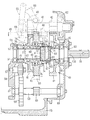
以下に、本願発明を作業車両としてのトラクタに適用した実施形態を図面(図1〜図10)に基づいて説明する。図1はトラクタの左側面図、図2はキャビン内部の平面図、図3は動力伝達系のスケルトン図、図4はミッションケース後部の側面断面図、図5はPTO変速機構が低速の状態を示す説明図、図6はPTO変速機構が高速の状態を示す説明図、図7はPTO変速機構が中立の状態を示す説明図、図8はPTO変速機構が中立で且つ逆転クラッチ入りの状態を示す説明図、図9は油圧回路及びコントローラの機能ブロック図、図10はPTO逆転自動制御のフローチャートである。   Hereinafter, an embodiment in which the present invention is applied to a tractor as a work vehicle will be described with reference to the drawings (FIGS. 1 to 10). 1 is a left side view of the tractor, FIG. 2 is a plan view of the interior of the cabin, FIG. 3 is a skeleton diagram of the power transmission system, FIG. 4 is a side sectional view of the rear of the transmission case, and FIG. FIG. 6 is an explanatory view showing a high speed state of the PTO transmission mechanism, FIG. 7 is an explanatory view showing a neutral state of the PTO transmission mechanism, and FIG. 8 is a state where the PTO transmission mechanism is neutral and includes a reverse clutch. FIG. 9 is a functional block diagram of a hydraulic circuit and a controller, and FIG. 10 is a flowchart of PTO reverse rotation automatic control.

(1).トラクタの概要
まず始めに、図1及び図2を参照しながら、トラクタ1の概要について説明する。
(1). First, an outline of the tractor 1 will be described with reference to FIGS. 1 and 2.

実施形態におけるトラクタ1の走行機体2は、走行部としての左右一対の前車輪3と同じく左右一対の後車輪4とで支持されている。走行機体2の前部に搭載されたディーゼル式エンジン5にて前車輪3及び後車輪4を駆動することにより、トラクタ1は前後進走行するように構成されている。エンジン5はボンネット6にて覆われている。走行機体2の上面にはキャビン7(操縦部)が設置され、該キャビン7の内部には、操縦座席8と、かじ取りすることによって前車輪3の操向方向を左右に動かすようにした操縦ハンドル9(丸ハンドル)とが配置されている。キャビン7の外側部には、オペレータが乗降するステップ10が設けられ、該ステップ10より内側で且つキャビン7の底部より下側には、エンジン5に燃料を供給する燃料タンク11が設けられている。   The traveling machine body 2 of the tractor 1 in the embodiment is supported by a pair of left and right rear wheels 4 as well as a pair of left and right front wheels 3 as a traveling unit. The tractor 1 is configured to travel forward and backward by driving the front wheels 3 and the rear wheels 4 with a diesel engine 5 mounted on the front portion of the traveling machine body 2. The engine 5 is covered with a bonnet 6. A cabin 7 (steering unit) is installed on the upper surface of the traveling machine body 2, and the steering handle 8 is steered inside the cabin 7 so as to move the steering direction of the front wheel 3 left and right by steering. 9 (round handle) is arranged. A step 10 on which the operator gets on and off the cabin 7 is provided, and a fuel tank 11 for supplying fuel to the engine 5 is provided on the inner side of the cabin 10 and below the bottom of the cabin 7. .

図1及び図2に示すように、キャビン7内の操縦ハンドル9は、操縦座席8の前方に位置する操縦コラム100上に配置されている。操縦コラム100の左側には、走行機体2の進行方向を前進と後進とに切り換え操作するための前後進切換レバー101と、エンジン5からの動力を継断する油圧クラッチ(図示せず)を切り操作するためのクラッチペダル102とが配置されている。操縦コラム100の右側には、走行機体2を制動操作するための左右一対のブレーキペダル103が配置されている。キャビン7内の床板104のうち操縦コラム100の右側(ブレーキペダル103の近傍)には、エンジン回転数を増減速させるためのアクセルペダル105が配置されている。   As shown in FIGS. 1 and 2, the steering handle 9 in the cabin 7 is disposed on a steering column 100 located in front of the steering seat 8. On the left side of the control column 100, a forward / reverse switching lever 101 for switching the traveling direction of the traveling machine body 2 between forward and reverse, and a hydraulic clutch (not shown) for disconnecting power from the engine 5 are disconnected. A clutch pedal 102 for operation is arranged. On the right side of the steering column 100, a pair of left and right brake pedals 103 for braking the traveling machine body 2 are disposed. On the right side of the steering column 100 (in the vicinity of the brake pedal 103) of the floor plate 104 in the cabin 7, an accelerator pedal 105 for increasing and decreasing the engine speed is disposed.

操縦座席8の左右両側にはサイドコラム106,107が設けられている。左サイドコラム106上には、後述する油圧式無段変速機20の出力及び回転数を作業状態に応じて所定範囲に設定保持するための副変速レバー108と、後述するPTO軸18の出力を複数段(実施形態では正転2段)及び中立に切り換え操作するPTO変速操作手段としてのPTO変速レバー109とが前後傾動操作可能に配置されている。副変速レバー108の前方には、ブレーキペダル103を踏み込み位置に保持するための駐車ブレーキレバー110が配置されている。PTO変速レバー109の後方であって、操縦座席8における背もたれ8aの後方一側寄り部位に、後述するPTO軸18の逆転駆動操作を実行するPTO逆転操作手段としてのPTO逆転レバー111がPTO変速レバー109とは別個に配置されている。実施形態のPTO逆転レバー111は縦軸112回りに前後回動操作可能に構成されている。   Side columns 106 and 107 are provided on the left and right sides of the control seat 8. On the left side column 106, the output of the hydraulic continuously variable transmission 20 (described later) and the rotational speed of the sub-transmission lever 108 for maintaining a predetermined range according to the working state, and the output of the PTO shaft 18 (described later) are provided. A PTO speed change lever 109 as a PTO speed change operating means for switching between a plurality of speeds (in the embodiment, two forward rotations) and a neutral position is disposed so as to be able to tilt forward and backward. A parking brake lever 110 for holding the brake pedal 103 in the depressed position is disposed in front of the auxiliary transmission lever 108. A PTO reverse lever 111 as a PTO reverse operation means for performing a reverse drive operation of the PTO shaft 18 to be described later is provided on the rear side of the backrest 8a of the control seat 8 and behind the PTO speed change lever 109. 109 is arranged separately. The PTO reverse lever 111 of the embodiment is configured to be capable of rotating back and forth around the vertical axis 112.

右サイドコラム107上には、走行機体2の前進、停止、後退及びその車速を無段階に変更操作するための主変速レバー113や、走行機体2の後方に配置されるポテトハーベスタ等の作業部(図示せず)の高さ位置を手動にて変更調節するための作業部調節レバー114等が配置されている。   On the right side column 107, a main transmission lever 113 for stepping forward, stopping, retreating and changing the vehicle speed of the traveling machine body 2 and a working part such as a potato harvester arranged behind the traveling machine body 2 A working unit adjustment lever 114 and the like for manually changing and adjusting the height position (not shown) are disposed.

一方、図1に示すように、走行機体2は、フロントバンパ12及び前車軸ケース(図示せず)を有するエンジンフレーム13と、エンジンフレーム13の後部にボルトにて取り外し可能に固定された左右の機体フレーム14を備えている。機体フレーム14の後部には、エンジン5からの動力を適宜変速して前車輪3、後車輪4及び後述するPTO軸18に伝達するためのミッションケース15が搭載されている。後車輪4は、ミッションケース15の外側面から外向きに突出するように装着された後車軸ケース(図示せず)を介して取り付けられている。左右の後車輪4の上方は、機体フレーム14に固定されたフェンダ16にて覆われている。   On the other hand, as shown in FIG. 1, the traveling machine body 2 includes an engine frame 13 having a front bumper 12 and a front axle case (not shown), and left and right left and right fixed to the rear portion of the engine frame 13 with bolts. A body frame 14 is provided. A transmission case 15 is mounted on the rear part of the body frame 14 for appropriately shifting the power from the engine 5 and transmitting it to the front wheels 3, the rear wheels 4, and a PTO shaft 18 described later. The rear wheel 4 is attached via a rear axle case (not shown) mounted so as to protrude outward from the outer surface of the mission case 15. The upper part of the left and right rear wheels 4 is covered with a fender 16 fixed to the body frame 14.

ミッションケース15の後部上面には、ポテトハーベスタ等の作業部を昇降動させるための油圧式昇降機構17が着脱可能に取り付けられている。詳細は図示していないが、作業部はミッションケース15の後部に3点リンク機構を介して連結される。ミッションケース15の後面には、作業部にPTO駆動力を伝達するためのPTO軸18が後ろ向きに突設されている。   On the rear upper surface of the mission case 15, a hydraulic lifting mechanism 17 for lifting and lowering a working portion such as a potato harvester is detachably attached. Although not shown in detail, the working unit is connected to the rear part of the mission case 15 via a three-point link mechanism. On the rear surface of the mission case 15, a PTO shaft 18 for transmitting a PTO driving force to the working unit is provided to project rearward.

(2).トラクタの動力伝達系
次に、図3を参照しながら、トラクタ1の動力伝達系について説明する。
(2). Next, the power transmission system of the tractor 1 will be described with reference to FIG.

実施形態のトラクタ1においては、エンジン5の動力が油圧式無段変速機20を介してミッションケース15に伝達され、ミッションケース15から前車輪3、後車輪4及びPTO軸18に分配するように構成されている。油圧式無段変速機20は、容量可変型の油圧ポンプ21と油圧モータ22とを備えている。油圧ポンプ21における回転斜板(図示せず)の傾斜角度を変更調節して、油圧モータ22への作動油の吐出方向及び吐出量を変更することにより、油圧モータ22から突出したモータ出力軸24の回転方向及び回転数が任意に調節される構成になっている。なお、実施形態の油圧式無段変速機20は、ミッションケース15に隣接して設けられるか、又は、ミッションケース15に外付けされている。   In the tractor 1 of the embodiment, the power of the engine 5 is transmitted to the transmission case 15 via the hydraulic continuously variable transmission 20 and distributed from the transmission case 15 to the front wheels 3, the rear wheels 4 and the PTO shaft 18. It is configured. The hydraulic continuously variable transmission 20 includes a variable displacement hydraulic pump 21 and a hydraulic motor 22. The motor output shaft 24 that protrudes from the hydraulic motor 22 is obtained by changing and adjusting the inclination angle of a rotary swash plate (not shown) in the hydraulic pump 21 to change the discharge direction and discharge amount of the hydraulic oil to the hydraulic motor 22. The rotation direction and the number of rotations are arbitrarily adjusted. The hydraulic continuously variable transmission 20 according to the embodiment is provided adjacent to the mission case 15 or is externally attached to the mission case 15.

油圧式無段変速機20は、エンジン5から突出して油圧ポンプ21を貫通したポンプ出力軸23経由の動力伝達経路と、油圧モータ22から突出したモータ出力軸24経由の動力伝達経路との2つの経路を有している。実施形態の油圧式無段変速機20は、ポンプ出力軸23経由の回転動力とモータ出力軸24経由の回転動力とからなる合成動力によって、前車輪3及び後車輪4を回転駆動させる油圧・機械式駆動モード(HMTモード)と、モータ出力軸24経由の回転動力だけで前車輪3及び後車輪4を回転駆動させる油圧式駆動モード(HSTモード)とを切り換えて実行し得るように構成されている。   The hydraulic continuously variable transmission 20 has two power transmission paths: a power transmission path via a pump output shaft 23 protruding from the engine 5 and penetrating the hydraulic pump 21; and a power transmission path via a motor output shaft 24 protruding from the hydraulic motor 22. Have a route. The hydraulic continuously variable transmission 20 according to the embodiment is a hydraulic / mechanical machine that rotationally drives the front wheels 3 and the rear wheels 4 by combined power composed of rotational power via the pump output shaft 23 and rotational power via the motor output shaft 24. And a hydraulic drive mode (HST mode) in which the front wheel 3 and the rear wheel 4 are driven to rotate only by the rotational power via the motor output shaft 24. Yes.

HMTモードの場合は、ミッションケース15内にある伝動切換機構25にて、ポンプ出力軸23経由の回転動力とモータ出力軸24経由の回転動力とが合成され、当該合成動力が伝動切換機構25から中間軸26に伝達される。HSTモードの場合は、モータ出力軸24経由の回転動力のみが伝動切換機構25を介して中間軸26に伝達される。   In the HMT mode, the transmission switching mechanism 25 in the transmission case 15 combines the rotational power via the pump output shaft 23 and the rotational power via the motor output shaft 24, and the combined power is transmitted from the transmission switching mechanism 25. It is transmitted to the intermediate shaft 26. In the HST mode, only the rotational power via the motor output shaft 24 is transmitted to the intermediate shaft 26 via the transmission switching mechanism 25.

いずれのモードの場合も、中間軸26に伝達された回転動力は、副変速機構27を介して前車輪3側と後車輪4側とに分岐される。前車輪3側では、副変速機構27から前輪増速機構28、前後両端に自在継手を有する推進軸29及びフロントアクスル機構30を経由して、左右の前車輪3を回転可能に支持する前輪出力軸31に動力伝達される。後車輪4側においては、副変速機構27から後輪デフ機構32を介して、左右の後車輪4を回転可能に支持する後輪出力軸33に動力伝達される。なお、中間軸26、副変速機構27、前輪増速機構28及び後輪デフ機構32等は、前述した伝動切換機構25と同様に、ミッションケース15内に収容されている。   In any mode, the rotational power transmitted to the intermediate shaft 26 is branched to the front wheel 3 side and the rear wheel 4 side via the auxiliary transmission mechanism 27. On the front wheel 3 side, a front wheel output that rotatably supports the left and right front wheels 3 via the auxiliary transmission mechanism 27, the front wheel speed increasing mechanism 28, the propulsion shaft 29 having universal joints at both front and rear ends, and the front axle mechanism 30. Power is transmitted to the shaft 31. On the rear wheel 4 side, power is transmitted from the auxiliary transmission mechanism 27 via the rear wheel differential mechanism 32 to the rear wheel output shaft 33 that rotatably supports the left and right rear wheels 4. The intermediate shaft 26, the auxiliary transmission mechanism 27, the front wheel speed increasing mechanism 28, the rear wheel differential mechanism 32, and the like are accommodated in the transmission case 15 in the same manner as the transmission switching mechanism 25 described above.

(3).PTO駆動系の概略
次に、図3〜図8を参照しながら、PTO駆動系の概略について説明する。
(3). Outline of PTO Drive System Next, an outline of the PTO drive system will be described with reference to FIGS.

ポンプ出力軸23の回転動力は、選択中のモードに関係なく、動力伝達継断用のPTOクラッチ39を介して、ミッションケース15内の後部に配置されたPTO変速機構40に伝達される。図4に示すように、実施形態では、PTOクラッチ39として湿式多板クラッチを採用している。なお、ポンプ出力軸23の動力の一部は、ポンプ出力軸23のうちPTOクラッチ39よりも上流側から、伝達ギヤ機構38(図3及び図4参照)を介して油圧式昇降機構17のチャージポンプ(図示せず)に分岐して伝達される。   The rotational power of the pump output shaft 23 is transmitted to the PTO speed change mechanism 40 disposed in the rear portion of the transmission case 15 via the power transmission interrupting PTO clutch 39 regardless of the selected mode. As shown in FIG. 4, in the embodiment, a wet multi-plate clutch is employed as the PTO clutch 39. Part of the power of the pump output shaft 23 is charged from the upstream side of the PTO clutch 39 in the pump output shaft 23 through the transmission gear mechanism 38 (see FIGS. 3 and 4). It is branched and transmitted to a pump (not shown).

PTO変速機構40は、PTO軸18の出力を複数段(実施形態では正転2段)及び中立に変速するためのものであり、ポンプ出力軸23にPTOクラッチ39を介して同心状に連結されたPTO推進軸41と、PTO推進軸41と平行状に延びるPTO軸18に被嵌された低速ギヤ44、高速ギヤ45及び中立兼逆転ギヤ46とを備えている。   The PTO transmission mechanism 40 is for shifting the output of the PTO shaft 18 in a plurality of stages (two forward rotations in the embodiment) and neutrally, and is concentrically connected to the pump output shaft 23 via the PTO clutch 39. The PTO propulsion shaft 41 and a low speed gear 44, a high speed gear 45 and a neutral / reverse gear 46 which are fitted on the PTO shaft 18 extending in parallel with the PTO propulsion shaft 41 are provided.

詳細については後述するが、PTO変速レバー109を中立以外の位置(低速側又は高速側)に変速操作すると、PTOクラッチ油圧電磁弁123(図9参照)の切換駆動にて、アクチュエータ手段としてのPTOクラッチシリンダ122(図3及び図9参照)が作動し、PTOクラッチ39が動力接続状態になる。これにより、ポンプ出力軸23とPTO推進軸41とが一体回転するように連結され、ポンプ出力軸23からPTO推進軸41に向けて回転動力が伝達される結果、PTO軸18が正転方向に回転駆動するように構成されている(図5及び図6参照)。また、実施形態では、PTO変速レバー109を中立側に操作すると共に、PTO逆転レバー111を逆転入り操作すると、PTOクラッチ油圧電磁弁123の連続的な切換駆動にてPTOクラッチシリンダ122が伸縮作動する結果、PTOクラッチ39の入り切り作動が繰り返され、当該繰り返しの作用にてPTO軸18が間欠的(小刻み)に逆転駆動する構成になっている。   Although details will be described later, when the PTO shift lever 109 is shifted to a position other than the neutral position (low speed side or high speed side), the PTO clutch hydraulic solenoid valve 123 (see FIG. 9) is driven to switch the PTO as the actuator means. The clutch cylinder 122 (see FIGS. 3 and 9) is operated, and the PTO clutch 39 is in a power connection state. As a result, the pump output shaft 23 and the PTO propulsion shaft 41 are connected to rotate integrally, and the rotational power is transmitted from the pump output shaft 23 toward the PTO propulsion shaft 41. As a result, the PTO shaft 18 moves in the forward direction. It is configured to rotate (see FIGS. 5 and 6). In the embodiment, when the PTO shift lever 109 is operated to the neutral side and the PTO reverse rotation lever 111 is operated to reversely rotate, the PTO clutch cylinder 122 is expanded and contracted by continuous switching drive of the PTO clutch hydraulic solenoid valve 123. As a result, the on / off operation of the PTO clutch 39 is repeated, and the PTO shaft 18 is reversely driven intermittently (in small increments) by the repeated action.

PTO推進軸41には、PTO軸18の低速ギヤ44に常時噛み合う低速入力ギヤ42と、PTO軸18の高速ギヤ45に常時噛み合う高速入力ギヤ43とが一体的に固着されている。これらギヤ42,44(又は43,45)の噛み合いによって、PTO推進軸41はPTO軸18に動力伝達可能に連結されている。   The PTO propulsion shaft 41 is integrally fixed with a low speed input gear 42 that always meshes with the low speed gear 44 of the PTO shaft 18 and a high speed input gear 43 that always meshes with the high speed gear 45 of the PTO shaft 18. The PTO propulsion shaft 41 is connected to the PTO shaft 18 so that power can be transmitted by meshing of the gears 42 and 44 (or 43 and 45).

低速ギヤ44及び高速ギヤ45は、PTO軸18の正転駆動力を変速する正転変速ギヤ手段に相当するものであり、中立兼逆転ギヤ46は、逆転切換機構51からの回転動力を受け取る減速ギヤ手段に相当するものである。実施形態では、PTO軸18の突出端側に低速ギヤ44が位置し、基端側に高速ギヤ45が位置している。そして、低速ギヤ44と高速ギヤ45との間に中立兼逆転ギヤ46が位置している。   The low speed gear 44 and the high speed gear 45 correspond to forward rotation gear means for shifting the forward driving force of the PTO shaft 18, and the neutral / reverse gear 46 is a deceleration that receives the rotational power from the reverse rotation switching mechanism 51. This corresponds to gear means. In the embodiment, the low speed gear 44 is located on the protruding end side of the PTO shaft 18, and the high speed gear 45 is located on the base end side. A neutral / reverse gear 46 is located between the low speed gear 44 and the high speed gear 45.

PTO軸18には、変速スライダ47を相対回転不能で且つ軸線方向にスライド可能にスプライン嵌合させている。この変速スライダ47の作用にて、低速ギヤ44、高速ギヤ45及び中立兼逆転ギヤ46はPTO軸18に択一的に連結される。変速スライダ47には、PTO推進軸41やPTO軸18と平行状に配置されたシフタ軸49に沿ってスライド移動可能な変速シフトフォーク48を係合させている。変速シフトフォーク48は、PTO変速リンク機構50を介してキャビン7内のPTO変速レバー109に連動連結されている。   A shift slider 47 is spline-fitted to the PTO shaft 18 so as not to be relatively rotatable and to be slidable in the axial direction. The low speed gear 44, the high speed gear 45, and the neutral / reverse gear 46 are selectively connected to the PTO shaft 18 by the action of the speed change slider 47. A shift shift fork 48 that is slidable along a shifter shaft 49 arranged in parallel to the PTO propulsion shaft 41 and the PTO shaft 18 is engaged with the shift slider 47. The shift shift fork 48 is linked to a PTO shift lever 109 in the cabin 7 via a PTO shift link mechanism 50.

PTO変速レバー109の変速操作にて変速シフトフォーク48をシフタ軸49に沿ってスライド移動させ、変速スライダ47をPTO軸18に沿ってスライド移動させることにより、択一的に選択されたギヤ44〜46のいずれかがPTO軸18に連結される。低速ギヤ44が選択された低速駆動状態、又は高速ギヤ45が選択された高速駆動状態のときは、低速又は高速の正転方向の回転動力(正転駆動力)がPTO推進軸41からPTO軸18に伝達され、PTO軸18が正転方向に回転駆動する(図5及び図6参照)。中立兼逆転ギヤ46にはPTO推進軸41から直接動力伝達できないので、中立兼逆転ギヤ46が選択された中立状態のときは、後述する逆転切換機構51からの回転動力が中立兼逆転ギヤ46に伝達されない限り、PTO軸18に回転動力が伝達されず、駆動停止状態になる(図4及び図7参照)。   The shift shift fork 48 is slid along the shifter shaft 49 and the shift slider 47 is slid along the PTO shaft 18 by the shift operation of the PTO shift lever 109, so that the gears 44- Any one of 46 is connected to the PTO shaft 18. When the low-speed gear 44 is selected, or when the high-speed gear 45 is selected, the low-speed or high-speed rotational power in the forward direction (forward drive force) is transferred from the PTO propulsion shaft 41 to the PTO shaft. 18 and the PTO shaft 18 is rotationally driven in the forward rotation direction (see FIGS. 5 and 6). Since power cannot be transmitted directly from the PTO propulsion shaft 41 to the neutral / reverse gear 46, when the neutral / reverse gear 46 is in the neutral state, rotational power from the reverse rotation switching mechanism 51 (to be described later) is transmitted to the neutral / reverse gear 46. Unless it is transmitted, the rotational power is not transmitted to the PTO shaft 18 and the drive is stopped (see FIGS. 4 and 7).

ミッションケース15内のうちPTO軸18の下方には、PTO推進軸41の回転動力を利用してPTO軸18を逆転駆動させるための逆転切換機構51が配置されている。逆転切換機構51は、PTO軸18の基端部に取り付けられた逆転クラッチ52と、PTO推進軸41やPTO軸18と平行状に配置されたカウンタ軸53とを備えている。   A reverse rotation switching mechanism 51 for driving the PTO shaft 18 to rotate in reverse using the rotational power of the PTO propulsion shaft 41 is disposed in the mission case 15 below the PTO shaft 18. The reverse rotation switching mechanism 51 includes a reverse rotation clutch 52 attached to the proximal end portion of the PTO shaft 18 and a counter shaft 53 arranged in parallel with the PTO propulsion shaft 41 and the PTO shaft 18.

逆転クラッチ52は、カウンタ軸53への動力伝達を継断するためのものであり、PTO軸18の基端部に、相対回転可能で且つ軸線方向にスライド可能に被嵌されている。実施形態では、逆転クラッチ52として噛み合い式のドグクラッチを採用している。逆転クラッチ52の外周前端部には、クラッチギヤ54が一体的に形成されている。クラッチギヤ54は、PTO軸18とカウンタ軸53との間にある中継軸57に回転可能に軸支された中継ギヤ58と常時噛み合っている。   The reverse clutch 52 is for interrupting power transmission to the counter shaft 53, and is fitted to the base end portion of the PTO shaft 18 so as to be relatively rotatable and slidable in the axial direction. In the embodiment, a meshing dog clutch is employed as the reverse rotation clutch 52. A clutch gear 54 is integrally formed at the outer peripheral front end of the reverse clutch 52. The clutch gear 54 is always meshed with a relay gear 58 rotatably supported by a relay shaft 57 between the PTO shaft 18 and the counter shaft 53.

逆転クラッチ52を後方にスライド移動させた入り状態のとき(図8参照)は、逆転クラッチ52が高速ギヤ45に一体回転するように連結される。逆転クラッチ52を前方にスライド移動させた切り状態のとき(図4〜図7参照)は、両者52,45の連結が解除される。また、逆転クラッチ52には、前述のシフタ軸49に沿ってスライド移動可能な逆転シフトフォーク55を係合させている。逆転シフトフォーク55は、PTO逆転リンク機構56を介してキャビン7内のPTO逆転レバー111に連動連結されている。   When the reverse clutch 52 is slid rearward (see FIG. 8), the reverse clutch 52 is connected to the high speed gear 45 so as to rotate integrally. When the reverse clutch 52 is slid forward and is in a disconnected state (see FIGS. 4 to 7), the connection between the two clutches 52 and 45 is released. The reverse clutch 52 is engaged with a reverse shift fork 55 that is slidable along the shifter shaft 49 described above. The reverse shift fork 55 is linked to the PTO reverse lever 111 in the cabin 7 via the PTO reverse link mechanism 56.

カウンタ軸53には、大径で歯数の多い逆転入力ギヤ59と、小径で歯数の少ない逆転出力ギヤ60とが固着されている。逆転入力ギヤ59は中継軸57の中継ギヤ58に常時噛み合っており、逆転出力ギヤ60はPTO軸18の中立兼逆転ギヤ46に常時噛み合っている。   On the counter shaft 53, a reverse rotation input gear 59 having a large diameter and a large number of teeth and a reverse rotation output gear 60 having a small diameter and a small number of teeth are fixed. The reverse rotation input gear 59 is always meshed with the relay gear 58 of the relay shaft 57, and the reverse rotation output gear 60 is always meshed with the neutral / reverse gear 46 of the PTO shaft 18.

この場合、PTO変速機構40が中立状態であれば、逆転切換機構51からの回転動力にてPTO軸18が逆転駆動可能になる。実施形態においては、PTO変速機構40が中立状態で且つ逆転クラッチ52が入り状態のときに、逆転切換機構51からの回転動力にて中立兼逆転ギヤ46を回転駆動させることによって、PTO軸18が逆転駆動する構成になっている。   In this case, if the PTO transmission mechanism 40 is in a neutral state, the PTO shaft 18 can be driven in reverse by the rotational power from the reverse switching mechanism 51. In the embodiment, when the PTO speed change mechanism 40 is in the neutral state and the reverse rotation clutch 52 is in the engaged state, the neutral / reverse rotation gear 46 is rotationally driven by the rotational power from the reverse rotation switching mechanism 51, whereby the PTO shaft 18 is It is configured to drive in reverse.

すなわち、PTO逆転レバー111の逆転入り操作にて逆転シフトフォーク55をシフタ軸49に沿ってスライド移動させ、逆転クラッチ52をPTO軸18に沿って後方にスライド移動させると、逆転クラッチ52は入り状態になり、逆転クラッチ52と高速ギヤ45とが一体回転するように連結される。   That is, when the reverse shift fork 55 is slid along the shifter shaft 49 and the reverse clutch 52 is slid rearward along the PTO shaft 18 by the reverse rotation operation of the PTO reverse lever 111, the reverse clutch 52 is in the engaged state. Thus, the reverse clutch 52 and the high speed gear 45 are coupled so as to rotate integrally.

このとき、PTO変速レバー109を中立側に操作して、変速スライダ47にて中立兼逆転ギヤ46が選択されていれば(PTO変速機構40が中立状態であれば)、高速ギヤ45はPTO軸18に対して自由回転可能な状態になる一方、中立兼逆転ギヤ46とPTO軸18とが一体回転するように連結される。そうすると、PTOクラッチ39よりも下流側にあるPTO推進軸41の回転動力は、高速入力ギヤ43から高速ギヤ45及びクラッチギヤ54と中継ギヤ58とを介して、カウンタ軸53の逆転入力ギヤ59に伝達され、カウンタ軸53の逆転出力ギヤ60から中立兼逆転ギヤ46を介して、PTO軸18に逆転方向の回転動力(逆転駆動力)として伝達される。その結果、PTO軸18が逆転方向に回転駆動する(図8参照)。実施形態では、このときのPTO軸18の逆転速度が、低速での正転速度(PTO軸18が低速にて正転方向に回転駆動するときの速度)よりも更に遅くなるように設定されている。   At this time, if the PTO speed change lever 109 is operated to the neutral side and the neutral / reverse gear 46 is selected by the speed change slider 47 (if the PTO speed change mechanism 40 is in the neutral state), the high speed gear 45 is set to the PTO shaft. The neutral / reverse gear 46 and the PTO shaft 18 are connected so as to rotate integrally. Then, the rotational power of the PTO propulsion shaft 41 downstream from the PTO clutch 39 is transferred from the high speed input gear 43 to the reverse rotation input gear 59 of the counter shaft 53 via the high speed gear 45, the clutch gear 54 and the relay gear 58. The torque is transmitted from the reverse rotation output gear 60 of the counter shaft 53 to the PTO shaft 18 through the neutral / reverse gear 46 as rotational power (reverse driving force) in the reverse direction. As a result, the PTO shaft 18 is rotationally driven in the reverse direction (see FIG. 8). In the embodiment, the reverse rotation speed of the PTO shaft 18 at this time is set to be slower than the normal rotation speed at a low speed (the speed when the PTO shaft 18 is driven to rotate in the normal rotation direction at a low speed). Yes.

なお、PTO変速レバー109を中立以外(低速側又は高速側)に変速操作すると共に、PTO逆転レバー111を逆転入り操作した場合は、中立兼逆転ギヤ46がPTO軸18に対して自由回転可能な状態になるので、逆転切換機構51を経由した回転動力がPTO軸18に伝達されることはない。特に実施形態では、変速シフトフォーク48と逆転シフトフォーク55とが共通のシフタ軸49に沿ってスライド移動し、高速状態での変速シフトフォーク48のスライド位置(図6参照)と、入り状態での逆転シフトフォーク55のスライド位置(図8参照)とが一部重複するように設定されている。このため、PTO変速レバー109を高速側に変速操作すると共に、PTO逆転レバー111を逆転入り操作しようとしても、シフトフォーク48,55同士が互いにかち合うことになり、変速スライダ47と逆転クラッチ52との両方を同時に、高速ギヤ45に連結する事態は生じない。   Note that when the PTO speed change lever 109 is shifted to a position other than neutral (low speed side or high speed side) and the PTO reverse rotation lever 111 is operated reversely, the neutral / reverse gear 46 can freely rotate with respect to the PTO shaft 18. Therefore, the rotational power via the reverse rotation switching mechanism 51 is not transmitted to the PTO shaft 18. In particular, in the embodiment, the shift shift fork 48 and the reverse shift fork 55 slide and move along the common shifter shaft 49, and the shift position of the shift shift fork 48 in the high speed state (see FIG. 6) The sliding position of the reverse shift fork 55 (see FIG. 8) is set so as to partially overlap. For this reason, even if the PTO speed change lever 109 is operated to shift to the high speed side and the PTO reverse rotation lever 111 is operated to enter the reverse rotation, the shift forks 48 and 55 are engaged with each other. There is no situation where both are connected to the high speed gear 45 at the same time.

(4).PTO駆動系を構成する各部の詳細構造
次に、図4〜図8を参照しながら、PTO変速機構40を中心に、PTO駆動系を構成する各部の詳細構造について説明する。
(4). Detailed structure of each part constituting the PTO drive system Next, a detailed structure of each part constituting the PTO drive system will be described with reference to FIGS.

図4に示すように、PTO推進軸41は、ミッションケース15内の後部上側に設けられた玉軸受61,62にて回転可能に軸支されている。PTO推進軸41の低速入力ギヤ42は、PTO軸18の低速ギヤ44に対応してPTO推進軸41の後部側に位置している。高速入力ギヤ43は、PTO軸18の高速ギヤ45に対応してPTO推進軸41の前部側に位置している。   As shown in FIG. 4, the PTO propulsion shaft 41 is rotatably supported by ball bearings 61 and 62 provided on the rear upper side in the mission case 15. The low speed input gear 42 of the PTO propulsion shaft 41 is located on the rear side of the PTO propulsion shaft 41 corresponding to the low speed gear 44 of the PTO shaft 18. The high speed input gear 43 is positioned on the front side of the PTO propulsion shaft 41 corresponding to the high speed gear 45 of the PTO shaft 18.

PTO軸18は、PTO推進軸41と平行状な姿勢でミッションケース15の後面に形成された軸穴63を貫通しており、ミッションケース15内の後部中央付近に設けられた玉軸受64,65にて回転可能に軸支されている。PTO軸18には、突出端側(後ろ側、図4〜図8では右側)から基端側(前側)に向かって順に、低速ギヤ44、中立兼逆転ギヤ46、高速ギヤ45、逆転クラッチ52が取り付けられている。   The PTO shaft 18 passes through a shaft hole 63 formed on the rear surface of the mission case 15 in a posture parallel to the PTO propulsion shaft 41, and ball bearings 64, 65 provided in the vicinity of the rear center in the mission case 15. It is pivotally supported by. The PTO shaft 18 includes a low speed gear 44, a neutral / reverse gear 46, a high speed gear 45, and a reverse clutch 52 in order from the protruding end side (rear side, right side in FIGS. 4 to 8) to the base end side (front side). Is attached.

図5〜図8に示すように、低速ギヤ44及び高速ギヤ45は、それぞれ対応する玉軸受66,67を介してPTO軸18に回転可能に軸支されている。高速ギヤ45の後面側に一体形成された後ろボス部68には玉軸受69が被嵌されており、当該後ろボス部68に被嵌された玉軸受69にて中立兼逆転ギヤ46が回転可能に軸支されている。逆転クラッチ52はころ軸受70を介してPTO軸18に回転可能に軸支されている。   As shown in FIGS. 5 to 8, the low speed gear 44 and the high speed gear 45 are rotatably supported by the PTO shaft 18 via corresponding ball bearings 66 and 67, respectively. A ball bearing 69 is fitted on the rear boss 68 integrally formed on the rear surface side of the high speed gear 45, and the neutral and reverse gear 46 can be rotated by the ball bearing 69 fitted on the rear boss 68. Is pivotally supported. The reverse clutch 52 is rotatably supported on the PTO shaft 18 via a roller bearing 70.

低速ギヤ44の前面側に一体形成された前ボス部71の外周前端部には、複数個の低速用係合突起72が円周方向に沿って適宜間隔にて形成されている。中立兼逆転ギヤ46の後面側に一体形成された後ろボス部73は、高速ギヤ45の後ろボス部68よりも更に後方に突出しており、中立兼逆転ギヤ46における後ろボス部73の内周後端部には、複数個の中立用係合突起74が円周方向に沿って適宜間隔にて形成されている。高速ギヤ45における後ろボス部68の内周後端部にも、複数個の高速用係合突起75が円周方向に沿って適宜間隔にて形成されている。   A plurality of low-speed engagement protrusions 72 are formed at appropriate intervals along the circumferential direction at the outer peripheral front end portion of the front boss portion 71 integrally formed on the front surface side of the low-speed gear 44. The rear boss 73 integrally formed on the rear surface side of the neutral / reverse gear 46 protrudes further rearward than the rear boss 68 of the high speed gear 45, and the inner peripheral rear end of the rear boss 73 in the neutral / reverse gear 46. A plurality of neutral engaging projections 74 are formed at appropriate intervals along the circumferential direction. A plurality of high-speed engagement protrusions 75 are also formed at appropriate intervals along the circumferential direction at the inner peripheral rear end of the rear boss 68 in the high-speed gear 45.

高速ギヤ45の前面側に一体形成された前ボス部76の内周前端部には、複数個の逆転用係合突起77が円周方向に沿って適宜間隔にて形成されている一方、逆転クラッチ52の外周後端部には、高速ギヤ45の逆転用係合突起77に係合可能な複数個の逆転用係合爪78が円周方向に沿って適宜間隔にて形成されている。   A plurality of reverse rotation projections 77 are formed at appropriate intervals along the circumferential direction at the inner peripheral front end portion of the front boss portion 76 integrally formed on the front side of the high speed gear 45, while A plurality of reverse engaging claws 78 that can be engaged with the reverse engaging protrusions 77 of the high speed gear 45 are formed at the outer peripheral rear end of the clutch 52 at appropriate intervals along the circumferential direction.

PTO軸18の外周のうち低速ギヤ44と中立兼逆転ギヤ46との間は、スプライン溝を有する前後一対のスプライン部81,82になっており、当該スプライン部81,82に、スプライン穴を有する変速スライダ47が相対回転不能で且つ軸線方向にスライド可能に被嵌されている。   Between the low-speed gear 44 and the neutral / reverse gear 46 on the outer periphery of the PTO shaft 18, there are a pair of front and rear spline portions 81, 82 having spline grooves, and the spline portions 81, 82 have spline holes. The speed-change slider 47 is fitted so as not to be relatively rotatable and to be slidable in the axial direction.

変速スライダ47の内周後端部には、低速ギヤ44の低速用係合突起72と前後両スプライン部81,82とに係合可能な複数個の後ろ係合爪83が円周方向に沿って適宜間隔にて形成されている。また、変速スライダ47の内周中央部には、前後両スプライン部81,82に係合可能な複数個の中央係合爪84が円周方向に沿って適宜間隔にて形成されている。更に、変速スライダ47の内周前端部には、高速ギヤ45の高速用係合突起75と前スプライン部81とに係合可能な複数個の前係合爪85が円周方向に沿って適宜間隔にて形成されている。変速スライダ47の外周前端部には、中立兼逆転ギヤ46の中立用係合突起74に係合可能な複数個の外周係合爪86が円周方向に沿って適宜間隔にて形成されている。   A plurality of rear engagement claws 83 that can be engaged with the low-speed engagement protrusion 72 of the low-speed gear 44 and both the front and rear spline portions 81 and 82 are appropriately provided along the circumferential direction at the rear end portion of the inner periphery of the speed change slider 47. It is formed at intervals. A plurality of central engaging claws 84 that can be engaged with both the front and rear spline portions 81 and 82 are formed in the central portion of the inner periphery of the speed change slider 47 at appropriate intervals along the circumferential direction. Furthermore, a plurality of front engagement claws 85 that can be engaged with the high-speed engagement protrusions 75 of the high-speed gear 45 and the front spline portions 81 are appropriately provided along the circumferential direction at the inner peripheral front end of the speed change slider 47. It is formed at intervals. A plurality of outer peripheral engaging claws 86 that can be engaged with the neutral engaging protrusions 74 of the neutral / reverse gear 46 are formed at appropriate intervals along the circumferential direction at the outer peripheral front end of the speed change slider 47. .

中継ギヤ58を回転可能に軸支する中継軸57は、ミッションケース15内の中仕切り壁に、後ろ向きに突出するようにして固定されている。カウンタ軸53は、ミッションケース15内の後部下側に設けられた玉軸受87,88にて回転可能に軸支されている。カウンタ軸53の逆転入力ギヤ59は、中継軸57の中継ギヤ58に対応してカウンタ軸53の前部側に位置している。逆転出力ギヤ60は、PTO軸18の中立兼逆転ギヤ46に対応してカウンタ軸53の後部側に位置している。   The relay shaft 57 that rotatably supports the relay gear 58 is fixed to the partition wall in the mission case 15 so as to protrude rearward. The countershaft 53 is rotatably supported by ball bearings 87 and 88 provided on the lower side of the rear part in the mission case 15. The reverse input gear 59 of the counter shaft 53 is positioned on the front side of the counter shaft 53 corresponding to the relay gear 58 of the relay shaft 57. The reverse output gear 60 is located on the rear side of the counter shaft 53 corresponding to the neutral and reverse gear 46 of the PTO shaft 18.

以下に、PTO変速機構40の切換動作について説明する。図5に示すように、PTO逆転レバー111の逆転切り操作により高速ギヤ45の逆転用係合突起77と逆転クラッチ52の逆転用係合爪78との係合を解除した状態で、PTO変速レバー109を低速側に変速操作すると、変速スライダ47がPTO軸18に沿って後方に移動して、低速ギヤ44の低速用係合突起72と変速スライダ47の後ろ係合爪83とが係合すると共に、PTO軸18の後ろスプライン部82と変速スライダ47の中央係合爪84とが係合する。その結果、PTO軸18が低速にて正転方向に回転駆動する。   Hereinafter, the switching operation of the PTO transmission mechanism 40 will be described. As shown in FIG. 5, the PTO speed change lever 111 is disengaged between the reverse rotation engagement protrusion 77 of the high speed gear 45 and the reverse rotation engagement claw 78 of the reverse rotation clutch 52 by the reverse rotation operation of the PTO reverse rotation lever 111. When the gear 109 is shifted to the low speed side, the speed change slider 47 moves rearward along the PTO shaft 18 and the low speed engagement projection 72 of the low speed gear 44 and the rear engagement claw 83 of the speed change slider 47 engage. At the same time, the rear spline portion 82 of the PTO shaft 18 and the center engaging claw 84 of the speed change slider 47 are engaged. As a result, the PTO shaft 18 is driven to rotate in the forward direction at a low speed.

図6に示すように、PTO逆転レバー111を逆転切り操作した状態で、PTO変速レバー109を高速側に変速操作すると、変速スライダ47がPTO軸18に沿って前方に移動して、高速ギヤ45の高速用係合突起75と変速スライダ47の前係合爪85とが係合すると共に、PTO軸18の後ろスプライン部82と変速スライダ47の中央及び後ろ係合爪84,83とが係合する。その結果、PTO軸18が高速にて正転方向に回転駆動する。   As shown in FIG. 6, when the PTO speed change lever 109 is shifted to the high speed side while the PTO reverse rotation lever 111 is operated to rotate in the reverse direction, the speed change slider 47 moves forward along the PTO shaft 18 and the high speed gear 45 is moved. The high-speed engagement protrusion 75 and the front engagement claw 85 of the speed change slider 47 are engaged, and the rear spline portion 82 of the PTO shaft 18 and the center and rear engagement claws 84 and 83 of the speed change slider 47 are engaged. To do. As a result, the PTO shaft 18 is driven to rotate in the forward rotation direction at a high speed.

図7に示すように、PTO逆転レバー111を逆転切り操作した状態で、PTO変速レバー109を中立側に操作すると、変速スライダ47がPTO軸18に沿って移動して、中立兼逆転ギヤ46の中立用係合突起74と変速スライダ47の外周係合爪86とが係合すると共に、PTO軸18の後ろスプライン部82と変速スライダ47の前及び中央係合爪85,84とが係合する。その結果、PTO軸18が駆動停止状態になる。   As shown in FIG. 7, when the PTO speed change lever 109 is operated to the neutral side while the PTO reverse rotation lever 111 is operated to rotate in the reverse direction, the speed change slider 47 moves along the PTO shaft 18, The neutral engaging projection 74 and the outer peripheral engaging claw 86 of the transmission slider 47 are engaged, and the rear spline portion 82 of the PTO shaft 18 and the front and central engaging claws 85 and 84 of the transmission slider 47 are engaged. . As a result, the PTO shaft 18 is stopped.

図8に示すように、PTO変速レバー109を中立側に操作した状態で、PTO逆転レバー111を逆転入り操作すると、逆転クラッチ52がPTO軸18に沿って後方に移動して、高速ギヤ45の逆転用係合突起77と逆転クラッチ52の逆転用係合爪78とが係合する。その結果、PTO軸18が低速正転駆動時よりも更に遅い速度で逆転方向に回転駆動する。   As shown in FIG. 8, when the PTO reverse lever 111 is operated to enter the reverse direction while the PTO speed change lever 109 is operated to the neutral side, the reverse rotation clutch 52 moves rearward along the PTO shaft 18 and the high speed gear 45 The reverse rotation projection 77 and the reverse rotation engagement claw 78 of the reverse rotation clutch 52 are engaged. As a result, the PTO shaft 18 is rotationally driven in the reverse direction at a slower speed than during the low speed forward rotation driving.

以上の構成によると、走行機体2に搭載されたエンジン5から回転動力が伝達されるミッションケース15内のうちPTO軸18の近傍に、PTOクラッチ39よりも下流側から分岐した回転動力を伝達可能な逆転切換機構51を備えており、PTO変速機構40が中立状態のときは、逆転切換機構51からの動力にてPTO軸18が逆転駆動し得るように構成されている。   According to the above configuration, the rotational power branched from the downstream side of the PTO clutch 39 can be transmitted to the vicinity of the PTO shaft 18 in the mission case 15 where the rotational power is transmitted from the engine 5 mounted on the traveling machine body 2. When the PTO speed change mechanism 40 is in a neutral state, the PTO shaft 18 can be driven to rotate in reverse by the power from the reverse rotation switching mechanism 51.

PTO軸18の近傍は、ミッションケース15の内部の中でもスペースを確保し易い箇所であるから、このような箇所にPTO軸18を逆転駆動させるための逆転切換機構51を備えることにより、PTOクラッチ39よりも上流側の動力伝達経路(例えば伝動切換機構25や副変速機構27等)の構造を複雑化することなく、PTO軸18の独立的な逆転駆動に対応する構成を簡単に実現できる。このため、ミッションケース15の小型・軽量化、ひいては製造コスト抑制に貢献できる。   Since the vicinity of the PTO shaft 18 is a place where it is easy to secure a space in the inside of the mission case 15, a PTO clutch 39 is provided by providing a reverse rotation switching mechanism 51 for driving the PTO shaft 18 to rotate in such a place. The configuration corresponding to the independent reverse drive of the PTO shaft 18 can be easily realized without complicating the structure of the power transmission path (for example, the transmission switching mechanism 25 and the auxiliary transmission mechanism 27) on the upstream side. For this reason, the mission case 15 can be reduced in size and weight, and as a result, can contribute to manufacturing cost reduction.

また、実施形態では、PTO軸18上に、PTO推進軸41から逆転切換機構51に向けての回転動力の伝達を継断するための逆転クラッチ52と、PTO軸18の出力を変速するPTO変速機構40とが配置されており、PTO変速機構40における正転変速ギヤ手段を構成する高速ギヤ45と逆転切換機構51とが、逆転クラッチ52を介して動力継断可能に連結されているので、PTO関連の機構がPTO軸18及びその近傍にまとまることになり、PTOクラッチ39からPTO軸18への動力伝達経路をコンパクトに構成できる。この点も、ミッションケース15の小型・軽量化、ひいては製造コスト抑制の一助になる。   In the embodiment, the PTO shaft 18 has a reverse clutch 52 for interrupting transmission of rotational power from the PTO propulsion shaft 41 to the reverse rotation switching mechanism 51 on the PTO shaft 18, and a PTO shift for shifting the output of the PTO shaft 18. Since the mechanism 40 is arranged, and the high speed gear 45 constituting the forward transmission gear means in the PTO transmission mechanism 40 and the reverse switching mechanism 51 are connected via the reverse clutch 52 so that the power can be disconnected. The PTO-related mechanism is gathered around the PTO shaft 18 and the vicinity thereof, and the power transmission path from the PTO clutch 39 to the PTO shaft 18 can be made compact. This also helps to reduce the size and weight of the mission case 15 and thus reduce the manufacturing cost.

更に、PTO変速機構40が中立状態で且つ逆転クラッチ52が入り状態のときに、逆転切換機構51からの回転動力にて減速ギヤ手段としての中立兼逆転ギヤ46を駆動させることによって、PTO軸18が逆転駆動するように構成されている。この構成から分かるように、PTO出力用のファイナルギヤである中立兼逆転ギヤ46と逆転切換機構51とが別々に存在するから、PTO軸18近傍のスペースを有効利用して中立兼逆転ギヤ46を大径に(歯数を多く)することが可能であり、大きな減速比で減速された逆転駆動力を簡単に得られる。   Further, when the PTO transmission mechanism 40 is in the neutral state and the reverse clutch 52 is in the engaged state, the neutral / reverse gear 46 serving as the reduction gear means is driven by the rotational power from the reverse rotation switching mechanism 51, thereby causing the PTO shaft 18. Are configured to be driven in reverse. As can be seen from this configuration, the neutral / reverse gear 46, which is the final gear for PTO output, and the reverse switching mechanism 51 exist separately, so that the neutral / reverse gear 46 is effectively utilized by utilizing the space near the PTO shaft 18. It is possible to increase the diameter (increase the number of teeth), and it is possible to easily obtain the reverse driving force decelerated with a large reduction ratio.

その上、PTO軸18を逆転駆動させるための構成として、PTO変速機構40を構成する中立兼逆転ギヤ46を利用しているから、PTO変速機構40が低速又は高速駆動状態である限り、PTO軸18が逆転方向に回転駆動することはない。従って、PTOクラッチ39からPTO軸18への動力伝達経路のコンパクト化に寄与するだけでなく、PTO軸18の誤作動を確実に防止できる。   In addition, since the neutral / reverse gear 46 that constitutes the PTO transmission mechanism 40 is used as a configuration for driving the PTO shaft 18 in the reverse direction, the PTO shaft can be used as long as the PTO transmission mechanism 40 is in a low speed or high speed driving state. 18 is not rotationally driven in the reverse direction. Therefore, not only contributes to the compactness of the power transmission path from the PTO clutch 39 to the PTO shaft 18, but also the malfunction of the PTO shaft 18 can be reliably prevented.

ところで、PTO軸18を逆転駆動させる操作を実行する機会はまれであり、かかる操作に関しては、操作性向上よりも誤操作防止に重点を置いて設計すべきと考えられる。この点、PTO軸18の正転変速操作と逆転駆動操作とを1つの操作手段で実行できる構成を採用した場合は、オペレータが前記1つの操作手段を誤操作して、不要なときにPTO軸18を逆転駆動させる可能性は否定できない。   By the way, there is rarely an opportunity to execute an operation to drive the PTO shaft 18 in the reverse direction, and it is considered that such an operation should be designed with emphasis on prevention of erroneous operation rather than improvement in operability. In this regard, when adopting a configuration in which the forward shifting operation and the reverse driving operation of the PTO shaft 18 can be executed by one operating means, the operator erroneously operates the one operating means, and when unnecessary, the PTO shaft 18 is operated. The possibility of driving in reverse cannot be denied.

これに対して実施形態では、PTO変速機構40を変速操作するPTO変速操作手段としてのPTO変速レバー109とは別個に、PTO軸18の逆転駆動操作を実行するPTO逆転操作手段としてのPTO逆転レバー111を備えているから、オペレータは、PTO変速機構40の変速操作(PTO軸18の正転変速操作)と、PTO軸18の逆転駆動操作とを、それぞれ異なるレバー109,111の操作にて実行しなければならない。このため、PTO軸18を回転駆動させたい方向と逆向きに回転駆動させるような誤操作を著しく防止又は低減でき、PTO軸18駆動時の安全性が向上する。   In contrast, in the embodiment, a PTO reverse lever as a PTO reverse operation means for executing a reverse drive operation of the PTO shaft 18 separately from the PTO speed change lever 109 as a PTO speed change operation means for changing the speed of the PTO speed change mechanism 40. 111 is provided, the operator executes the shift operation of the PTO transmission mechanism 40 (forward rotation shift operation of the PTO shaft 18) and the reverse drive operation of the PTO shaft 18 by operating the levers 109 and 111, respectively. Must. For this reason, it is possible to remarkably prevent or reduce an erroneous operation of rotating the PTO shaft 18 in the direction opposite to the direction in which the PTO shaft 18 is desired to be rotated, and to improve the safety when driving the PTO shaft 18.

しかも、通常あまり操作することのないPTO逆転レバー111がPTO変速レバー109の後方に配置されているので、通常作業の際に、PTO逆転レバー111の存在が邪魔にならず、誤操作防止の点で高い効果を発揮するのである。   In addition, since the PTO reverse lever 111 that is not normally operated is disposed behind the PTO speed change lever 109, the presence of the PTO reverse lever 111 does not get in the way during normal work, and it is possible to prevent erroneous operation. It is highly effective.

(5).PTO軸の逆転駆動を間欠的に実行するための構成
次に、図9及び図10を参照しながら、PTO軸18の逆転駆動を間欠的に実行するための構成について説明する。
(5). Configuration for intermittently executing reverse rotation drive of PTO shaft Next, a configuration for intermittently executing reverse rotation drive of the PTO shaft 18 will be described with reference to FIGS. 9 and 10.

図9に示すように、トラクタ1の油圧回路120は、エンジン5の回転力にて作動する作業用油圧ポンプ121を備えている。この場合、ミッションケース15が作業油タンクとしても利用されていて、ミッションケース15内部の作動油が作業用油圧ポンプ121に供給される。一方、図3及び図9に示すように、ポンプ出力軸23とPTO推進軸41とを動力継断可能に連結するPTOクラッチ39には、アクチュエータ手段としての単動ばね付きタイプのPTOクラッチシリンダ122が取り付けられている。   As shown in FIG. 9, the hydraulic circuit 120 of the tractor 1 includes a working hydraulic pump 121 that is operated by the rotational force of the engine 5. In this case, the mission case 15 is also used as a working oil tank, and hydraulic oil inside the mission case 15 is supplied to the working hydraulic pump 121. On the other hand, as shown in FIGS. 3 and 9, the PTO clutch 39 that connects the pump output shaft 23 and the PTO propulsion shaft 41 so that the power can be disconnected is provided in a PTO clutch cylinder 122 of a single acting spring type as an actuator means. Is attached.

作業用油圧ポンプ121とPTOクラッチシリンダ122とは、3ポート2位置切換型のPTOクラッチ油圧電磁弁123を介して接続されている。PTOクラッチ油圧電磁弁123は、制御手段としてのコントローラ130に電気的に接続された電磁ソレノイド124を有している。PTOクラッチ油圧電磁弁123は、原則としてPTO変速レバー109の変速操作に対応した電磁ソレノイド124の励磁によって、PTOクラッチシリンダ122への作動油供給状態とPTOクラッチシリンダ122からの作動油排出状態とに切換駆動するように構成されている。   The working hydraulic pump 121 and the PTO clutch cylinder 122 are connected via a 3-port 2-position switching type PTO clutch hydraulic solenoid valve 123. The PTO clutch hydraulic solenoid valve 123 has an electromagnetic solenoid 124 electrically connected to a controller 130 as control means. In principle, the PTO clutch hydraulic solenoid valve 123 is switched between a hydraulic oil supply state to the PTO clutch cylinder 122 and a hydraulic oil discharge state from the PTO clutch cylinder 122 by excitation of the electromagnetic solenoid 124 corresponding to the shift operation of the PTO shift lever 109. It is configured to perform switching driving.

PTO変速レバー109の変速操作にてPTOクラッチ油圧電磁弁123を自動的に切換作動させると、PTOクラッチシリンダ122が伸縮作動して、PTOクラッチ39が入り切り作動する。その結果、ポンプ出力軸23からPTO推進軸41への動力伝達が接続状態又は遮断状態に選択的に切り換えられることになる。   When the PTO clutch hydraulic solenoid valve 123 is automatically switched by the speed change operation of the PTO speed change lever 109, the PTO clutch cylinder 122 is expanded and contracted, and the PTO clutch 39 is turned on and off. As a result, power transmission from the pump output shaft 23 to the PTO propulsion shaft 41 is selectively switched between the connected state and the disconnected state.

実施形態において、PTO変速レバー109を中立側に操作すると共に、PTO逆転レバー111を逆転入り操作した場合は、前述の通り、中立兼逆転ギヤ46とPTO軸18とが一体回転するように連結されると共に、逆転クラッチ52が入り作動して、逆転クラッチ52と高速ギヤ45とが一体回転するように連結される。その結果、PTO推進軸41の回転動力が、高速入力ギヤ43から高速ギヤ45及びクラッチギヤ54と中継ギヤ58とを介して、カウンタ軸53の逆転入力ギヤ59に伝達され、カウンタ軸53の逆転出力ギヤ60から中立兼逆転ギヤ46を介して、PTO軸18に逆転方向の回転動力(逆転駆動力)として伝達される。   In the embodiment, when the PTO speed change lever 109 is operated to the neutral side and the PTO reverse rotation lever 111 is operated to reversely rotate, the neutral / reverse rotation gear 46 and the PTO shaft 18 are connected to rotate integrally as described above. At the same time, the reverse clutch 52 is engaged and actuated so that the reverse clutch 52 and the high speed gear 45 are connected to rotate integrally. As a result, the rotational power of the PTO propulsion shaft 41 is transmitted from the high speed input gear 43 to the reverse rotation input gear 59 of the counter shaft 53 via the high speed gear 45, the clutch gear 54 and the relay gear 58. It is transmitted from the output gear 60 through the neutral / reverse gear 46 to the PTO shaft 18 as rotational power (reverse driving force) in the reverse direction.

このとき、PTOクラッチ油圧電磁弁123は、電磁ソレノイド124の励磁にて前述した各状態(作動油供給状態と作動油排出状態)に交互に切り換えられ、PTOクラッチシリンダ122が伸縮作動を繰り返す。このため、PTOクラッチ39の入り切り作動が強制的に繰り返され、当該繰り返しの作用にてPTO軸18の逆転駆動が間欠的(小刻み)に実行されるのである。   At this time, the PTO clutch hydraulic solenoid valve 123 is alternately switched to the above-described states (the hydraulic fluid supply state and the hydraulic fluid discharge state) by the excitation of the electromagnetic solenoid 124, and the PTO clutch cylinder 122 repeats the expansion and contraction operation. For this reason, the on / off operation of the PTO clutch 39 is forcibly repeated, and the reverse rotation of the PTO shaft 18 is intermittently (smallly) performed by the repeated operation.

このように構成すると、PTO変速レバー109を中立側に操作すると共に、PTO逆転レバー111を逆転入り操作した状態では、逆転切換機構51からの動力にてPTO軸18が間欠的に逆転駆動することになるから、例えば作業部に石等の異物を噛み込んだときに、走行機体2を後進させたりしなくても、その場で異物の噛み込みを解除できる。しかも、PTO軸18の逆転駆動は間欠的(小刻み)なインチング駆動であるから、異物の噛み込みを効率よく且つ確実に解除できる。   With this configuration, when the PTO speed change lever 109 is operated to the neutral side and the PTO reverse rotation lever 111 is operated for reverse rotation, the PTO shaft 18 is intermittently reversely driven by the power from the reverse rotation switching mechanism 51. Therefore, for example, when a foreign object such as a stone is caught in the working part, the biting of the foreign object can be released on the spot without moving the traveling machine body 2 backward. In addition, since the reverse drive of the PTO shaft 18 is an intermittent (small) inching drive, it is possible to efficiently and reliably release the foreign matter.

また、実施形態のPTOクラッチ39は、湿式多板クラッチであり且つこれを入り切り作動させるアクチュエータ手段としてのPTOクラッチシリンダ122を備えており、逆転クラッチ52が入り状態のときに、PTOクラッチシリンダ122によるPTOクラッチ39の入り切り作動を繰り返すことによって、PTO軸18が間欠的に逆転駆動するように構成されているから、例えばPTOクラッチ39としてドグクラッチを用いた場合に比べて噛み合わせショックを軽減でき、PTO軸18の間欠的な逆転駆動をスムーズに実行できるのである。   Further, the PTO clutch 39 of the embodiment is a wet multi-plate clutch and includes a PTO clutch cylinder 122 as an actuator means for turning on and off the clutch. When the reverse clutch 52 is in the engaged state, the PTO clutch cylinder 122 By repeatedly turning the PTO clutch 39 on and off, the PTO shaft 18 is configured to intermittently reversely rotate, so that, for example, the meshing shock can be reduced compared to the case where a dog clutch is used as the PTO clutch 39, and the PTO The intermittent reverse drive of the shaft 18 can be executed smoothly.

走行機体2に搭載された制御手段としてのコントローラ130は、後述するPTO変速ポジションセンサ134やPTO逆転入りセンサ135の検出情報に基づいて、PTOクラッチ39の入り切り制御を実行できると共に、トルク検出手段としてのPTOトルクセンサ136(詳細は後述する)の検出情報に基づいて、PTO逆転自動制御(PTO軸18の正転駆動と逆転駆動とを切り換える制御)を実行するものである。コントローラ130は、各種演算処理や制御を実行するCPU131のほか、制御プログラムやデータを記憶させる記憶手段としてのPROM132、制御プログラムやデータを一時的に記憶させるためのRAM133、及び、センサやアクチュエータ等とデータのやり取りをするための入出力インターフェイス等を備えている。   The controller 130 as a control means mounted on the traveling machine body 2 can execute on / off control of the PTO clutch 39 based on detection information from a PTO shift position sensor 134 and a PTO reverse rotation on / off sensor 135, which will be described later, and as torque detection means. PTO torque sensor 136 (details will be described later) is used to execute PTO reverse rotation automatic control (control for switching between forward rotation and reverse rotation of the PTO shaft 18). The controller 130 includes a CPU 131 for executing various arithmetic processes and controls, a PROM 132 as storage means for storing control programs and data, a RAM 133 for temporarily storing control programs and data, and sensors and actuators. An input / output interface for exchanging data is provided.

コントローラ130の入力インターフェイスには、PTO変速レバー109の操作位置を検出するPTO変速ポジションセンサ134、PTO逆転レバー111が入り操作状態か否かを検出するリミットスイッチ式のPTO逆転入りセンサ135、及び、PTO軸18の回転トルクを検出するトルク検出手段としてのPTOトルクセンサ136等が電気手的に接続されている。コントローラ130の出力インターフェイスには、前述したPTOクラッチ油圧電磁弁123の電磁ソレノイド124のほか、PTO変速レバー109を動力にて各操作位置まで移動させるPTO変速電動モータ138に対するPTO変速駆動回路137、及び、PTO逆転レバー111を動力にて入り切りの操作位置まで移動させるPTO逆転電動モータ140に対するPTO変速駆動回路139等が接続されている。   The input interface of the controller 130 includes a PTO shift position sensor 134 that detects the operation position of the PTO shift lever 109, a limit switch type PTO reverse rotation sensor 135 that detects whether or not the PTO reverse rotation lever 111 is in the operation state, and A PTO torque sensor 136 or the like as torque detecting means for detecting the rotational torque of the PTO shaft 18 is electrically connected. In addition to the electromagnetic solenoid 124 of the PTO clutch hydraulic solenoid valve 123 described above, the output interface of the controller 130 includes a PTO shift drive circuit 137 for a PTO shift electric motor 138 that moves the PTO shift lever 109 to each operation position by power, and A PTO shift drive circuit 139 and the like for the PTO reverse rotation electric motor 140 for moving the PTO reverse rotation lever 111 to the on / off operation position by power are connected.

PTOトルクセンサ136は、PTO軸18に作用する回転トルクTRから、作業部に石等の異物を噛み込んでいるか否かを検出するためのものである。実施形態のPTOトルクセンサ136は、ミッションケース15の後面に形成された軸穴63の箇所に、PTO軸18に関連付けて配置されている。PTO変速電動モータ138は、PTO変速レバー109を動力にて各操作位置に移動させることによって、変速スライダ47のスライド移動を制御するものである。また、PTO逆転電動モータ140は、PTO逆転レバー111を動力にて入り切りの操作位置まで移動させることによって、逆転クラッチ52のスライド移動を制御するものである。   The PTO torque sensor 136 is for detecting whether or not a foreign object such as a stone is caught in the working part from the rotational torque TR acting on the PTO shaft 18. The PTO torque sensor 136 according to the embodiment is disposed in association with the PTO shaft 18 at a shaft hole 63 formed on the rear surface of the mission case 15. The PTO speed change electric motor 138 controls the sliding movement of the speed change slider 47 by moving the PTO speed change lever 109 to each operation position by power. The PTO reverse rotation electric motor 140 controls the sliding movement of the reverse rotation clutch 52 by moving the PTO reverse rotation lever 111 to the on / off operation position by power.

なお、PTO変速電動モータ138に代えて、変速スライダ47を直接スライド移動させるアクチュエータを採用したり、PTO逆転電動モータ140に代えて、逆転クラッチ52を直接スライド移動させるアクチュエータを採用したりしてもよい。   In place of the PTO variable speed electric motor 138, an actuator that directly slides the shift slider 47 may be employed, or instead of the PTO reverse rotation electric motor 140, an actuator that directly slides the reverse clutch 52 may be employed. Good.

以下に、図10のフローチャートを参照しながら、コントローラ130によるPTO逆転自動制御(PTO軸18の正転駆動と逆転駆動とを切り換える制御)の一例について説明する。ここで、後述するPTO軸間欠逆転制御を実行する基準(しきい値)になる正転設定トルクTR0+や、その後のPTO軸正転復帰制御を実行する基準(しきい値)になる逆転設定トルクTR0−に関するデータは、コントローラ130のPROM132等に記憶させることで予め設定されている。実施形態では、PTO軸18における正転方向の回転トルクTRの符号が正(プラス)に、逆転方向の回転トルクTRの符号が負(マイナス)になるように設定されている。   Hereinafter, an example of PTO reverse rotation automatic control (control for switching between forward rotation and reverse rotation of the PTO shaft 18) by the controller 130 will be described with reference to the flowchart of FIG. Here, the forward rotation setting torque TR0 + that becomes a reference (threshold value) for executing PTO axis intermittent reverse rotation control, which will be described later, and the reverse rotation setting torque that becomes a reference (threshold value) for executing subsequent PTO axis forward rotation return control Data relating to TR0- is preset by being stored in the PROM 132 of the controller 130 or the like. In the embodiment, the sign of the rotational torque TR in the forward direction on the PTO shaft 18 is set to be positive (plus), and the sign of the rotational torque TR in the reverse direction is set to be negative (minus).

まず、PTO逆転自動制御のスタートに続いて、PTO変速ポジションセンサ134の検出値と、PTO逆転入りセンサ135の検出値と、PTOトルクセンサ136の検出値TRとを読み込み(ステップS1)、次いで、PTO変速ポジションセンサ134の検出値に基づいて、PTO変速レバー109が中立以外(低速側又は高速側)の操作状態か否かを判別すると共に、PTO逆転入りセンサ135の検出値に基づいて、PTO逆転レバー111が切り状態か否かを判別する(ステップS2)。   First, following the start of automatic PTO reverse rotation control, the detection value of the PTO shift position sensor 134, the detection value of the PTO reverse rotation entering sensor 135, and the detection value TR of the PTO torque sensor 136 are read (step S1), and then Based on the detected value of the PTO shift position sensor 134, it is determined whether or not the PTO shift lever 109 is in an operation state other than neutral (low speed side or high speed side), and based on the detected value of the PTO reverse rotation sensor 135, It is determined whether or not the reverse lever 111 is in the cut state (step S2).

PTO変速レバー109が中立状態にあるか、又はPTO逆転レバー111が入り状態にあると判断されたときは(S2:NO)、トラクタ1がPTO軸18を正転駆動させる通常作業の状態にないことを意味しているので、そのままリターンする。PTO変速レバー109が中立以外の操作状態にあり且つPTO逆転レバー111が切り状態にあると判断されたときは(S2:YES)、トラクタ1がPTO軸18を正転駆動させる通常作業の状態にあることを意味しているので、次いで、ステップS1にて読み込まれたPTOトルクセンサ130の検出値TRが予め設定された正転設定トルクTR0+(正転方向の設定トルク)以上であるか否かを判別する(ステップS3)。   When it is determined that the PTO speed change lever 109 is in the neutral state or the PTO reverse rotation lever 111 is in the engaged state (S2: NO), the tractor 1 is not in the normal work state for driving the PTO shaft 18 in the forward direction. This means that it returns. When it is determined that the PTO speed change lever 109 is in an operation state other than neutral and the PTO reverse rotation lever 111 is in the off state (S2: YES), the tractor 1 enters a normal operation state in which the PTO shaft 18 is driven to rotate forward. Since this means that there is, then whether or not the detected value TR of the PTO torque sensor 130 read in step S1 is equal to or greater than a preset normal rotation set torque TR0 + (set torque in the normal rotation direction). Is discriminated (step S3).

PTOトルクセンサ130の検出値TRが正転設定トルクTR0+より小さいと判断されたときは(S3:NO)、PTO軸18に作用する負荷が小さく、通常作業に支障がない状態であるから、ステップS1に戻る。PTOトルクセンサ130の検出値TRが正転設定トルクTR0+以上であると判断されたときは(S6:YES)、例えば石等の異物を作業部に噛み込んだといった理由で、PTO軸18ひいてはエンジン5に大きな負荷がかかっている状態(過負荷状態)である。このような状態で通常作業を続行すると、エンジン5が過負荷で停止する(エンジンストップする)おそれがある。   If it is determined that the detected value TR of the PTO torque sensor 130 is smaller than the forward rotation set torque TR0 + (S3: NO), the load acting on the PTO shaft 18 is small and there is no problem in normal work. Return to S1. When it is determined that the detected value TR of the PTO torque sensor 130 is equal to or greater than the normal rotation set torque TR0 + (S6: YES), for example, a foreign object such as a stone is caught in the working part, and therefore the PTO shaft 18 and the engine 5 is a state in which a large load is applied (overload state). If normal work is continued in such a state, the engine 5 may stop due to overload (engine stop).

そこで、この場合はPTO軸間欠逆転制御を実行する(ステップS4)。PTO軸間欠逆転制御においては、まず、PTO変速電動モータ138の駆動にてPTO変速レバー109を中立側に移動させ、中立兼逆転ギヤ46とPTO軸18とを一体回転するように連結すると共に、PTO逆転電動モータ140の駆動にてPTO逆転レバー111を逆転入り側に移動させ、逆転クラッチ52と高速ギヤ45とを一体回転するように連結する。そして、PTOクラッチ油圧電磁弁123の連続的な切換駆動にてPTOクラッチシリンダ122が伸縮作動する結果、PTOクラッチ39の入り切り作動が繰り返され、当該繰り返しの作用にてPTO軸18が間欠的に逆転駆動するのである。   Therefore, in this case, PTO shaft intermittent reverse rotation control is executed (step S4). In the PTO shaft intermittent reverse rotation control, first, the PTO transmission electric motor 138 is driven to move the PTO transmission lever 109 to the neutral side, and the neutral / reverse rotation gear 46 and the PTO shaft 18 are connected to rotate integrally, By driving the PTO reverse rotation electric motor 140, the PTO reverse rotation lever 111 is moved to the reverse rotation start side, and the reverse rotation clutch 52 and the high speed gear 45 are connected to rotate integrally. Then, as a result of the PTO clutch cylinder 122 extending and contracting by the continuous switching drive of the PTO clutch hydraulic solenoid valve 123, the on / off operation of the PTO clutch 39 is repeated, and the PTO shaft 18 is intermittently reversed by the repeated action. Drive.

このように、正転駆動中のPTO軸18に作用する回転トルクTRが予め設定された正転設定トルクTR0+以上であるとき、すなわち正転駆動中のPTO軸18に過負荷がかかったときは、逆転切換機構51からの動力にてPTO軸18が逆転駆動するという構成を採用すると、例えば作業部に石等の異物を噛み込んだときに、自動的にPTO軸18が逆転駆動することになるから、走行機体2を後進させたりPTO逆転レバー111を手動操作したりしなくても、その場で異物の噛み込みを自動的に解除でき、噛み込み解除作業がより一層簡単になる。しかも、実施形態では、PTO軸18が間欠的に逆転駆動する(インチング駆動する)から、作業部における異物の噛み込み解除を効率よく且つ確実に行える。   Thus, when the rotational torque TR acting on the PTO shaft 18 during forward rotation is greater than or equal to the preset forward rotation set torque TR0 +, that is, when an overload is applied to the PTO shaft 18 during forward rotation driving. When the configuration in which the PTO shaft 18 is driven in reverse by the power from the reverse switching mechanism 51 is employed, for example, when a foreign object such as a stone is caught in the working unit, the PTO shaft 18 is automatically driven in reverse. Therefore, even if the traveling machine body 2 is not moved backward or the PTO reverse lever 111 is not manually operated, the foreign matter can be automatically released from the place, and the engagement release operation is further simplified. In addition, in the embodiment, since the PTO shaft 18 is intermittently reversely driven (inching driven), it is possible to efficiently and reliably release the foreign matter from the working portion.

ステップS4におけるPTO軸間欠逆転制御の後は、再びPTOトルクセンサ136の検出値TRを読み込む(ステップS5)。このときの検出値TRの符号は、PTO軸18が逆転駆動している関係で、負(マイナス)になっている。次いで、ステップS5にて読み込まれたPTOトルクセンサ130の検出値TRが予め設定された逆転設定トルクTR0−(逆転方向の設定トルク)以上であるか否かを判別する(ステップS6)。   After the PTO shaft intermittent reverse rotation control in step S4, the detection value TR of the PTO torque sensor 136 is read again (step S5). The sign of the detected value TR at this time is negative (minus) because the PTO shaft 18 is reversely driven. Next, it is determined whether or not the detected value TR of the PTO torque sensor 130 read in step S5 is equal to or greater than a preset reverse rotation set torque TR0− (set torque in the reverse rotation direction) (step S6).

PTOトルクセンサ130の検出値TRが逆転設定トルクTR0−より小さいと判断されたときは(S6:NO)、PTO軸18の回転駆動は逆向きになったものの、過負荷状態のまま(異物の噛み込みを解除できていない状態)であることを意味しているので、ステップS4のPTO軸間欠逆転制御に戻る。すなわち、PTO軸18に作用する過負荷を解消するまで(異物の噛み込みを解除するまで)、PTO軸18の間欠逆転駆動が実行されるのである。   When it is determined that the detected value TR of the PTO torque sensor 130 is smaller than the reverse rotation set torque TR0− (S6: NO), the rotational drive of the PTO shaft 18 is reversed, but remains in an overload state (foreign matter This means that the biting has not been released), and the process returns to the PTO shaft intermittent reverse rotation control in step S4. That is, the intermittent reverse drive of the PTO shaft 18 is executed until the overload acting on the PTO shaft 18 is eliminated (until the foreign object is released).

PTOトルクセンサ130の検出値TRが逆転設定トルクTR0−であると判断されたときは(S6:YES)、異物の噛み込みが解消されてPTO軸18に作用する負荷が十分に低下し、通常作業に支障がない状態になったことを意味しているので、次いで、PTO軸正転復帰制御を実行する(ステップS7)。   When it is determined that the detected value TR of the PTO torque sensor 130 is the reverse rotation set torque TR0− (S6: YES), the load acting on the PTO shaft 18 is sufficiently reduced because the foreign object biting is eliminated. Since this means that there is no trouble in the work, next, PTO axis forward rotation return control is executed (step S7).

PTO軸正転復帰制御においては、まず、PTO変速電動モータ138の駆動にてPTO変速レバー109を元の操作位置(低速側又は高速側)に移動させ、低速ギヤ44又は高速ギヤ45とPTO軸18とを一体回転するように連結すると共に、PTO逆転電動モータ140の駆動にてPTO逆転レバー111を逆転切り側に移動させ、逆転クラッチ52と高速ギヤ45との連結を解除する。そして、PTOクラッチ油圧電磁弁123の切換駆動にてPTOクラッチシリンダ122を伸長作動させ、PTOクラッチ39を入り作動させる(動力接続状態にする)。その結果、ポンプ出力軸23からPTO推進軸41を介してPTO軸18に正転方向の回転動力が伝達され、PTO軸18が元の正転駆動状態に復帰するのである。ステップS7におけるPTO軸正転復帰制御の後は、ステップS1に戻る。   In the PTO axis forward rotation return control, first, the PTO speed change electric motor 138 is driven to move the PTO speed change lever 109 to the original operation position (low speed side or high speed side), and the low speed gear 44 or the high speed gear 45 and the PTO axis. 18 and the PTO reverse rotation electric motor 140 are driven to move the PTO reverse rotation lever 111 to the reverse rotation side to release the connection between the reverse rotation clutch 52 and the high speed gear 45. Then, the PTO clutch cylinder 122 is extended by the switching drive of the PTO clutch hydraulic solenoid valve 123, and the PTO clutch 39 is engaged and operated (the power is connected). As a result, the rotational power in the forward rotation direction is transmitted from the pump output shaft 23 to the PTO shaft 18 via the PTO propulsion shaft 41, and the PTO shaft 18 returns to the original forward drive state. After the PTO axis forward rotation return control in step S7, the process returns to step S1.

このように制御すると、逆転駆動中のPTO軸18に作用する回転トルクTRが予め設定された逆転設定トルクTR0−以上であるとき、すなわち逆転駆動に移行したPTO軸18に対する過負荷が解消したときは、PTO軸18が元の正転駆動状態に自動的に復帰することになるから、異物の噛み込みを解除した後も、PTO逆転レバー111を手動操作することなく、通常作業の状態に復帰でき、オペレータの操作負担を軽減できる。   When controlled in this way, when the rotational torque TR acting on the PTO shaft 18 during reverse rotation driving is greater than or equal to the preset reverse rotation torque TR0-, that is, when the overload on the PTO shaft 18 that has shifted to reverse rotation driving has been resolved. Since the PTO shaft 18 automatically returns to the normal forward drive state, even after releasing the foreign matter, the PTO reverse lever 111 is returned to the normal operation state without manual operation. This can reduce the burden on the operator.

(6).その他
本願発明は、前述の実施形態に限らず、様々な態様に具体化できる。例えば本願発明はトラクタに限らず、田植機やコンバイン等の農作業機や、ホイルローダ等の特殊作業用車両にも適用可能である。また、PTO変速操作手段やPTO逆転操作手段は、レバータイプに限らず、ボタンタイプ(スイッチタイプ)であってもよい。その他、各部の構成は図示の実施形態に限定されるものではなく、本発明の趣旨を逸脱しない範囲で種々変更が可能である。
(6). Others The present invention is not limited to the above-described embodiment, and can be embodied in various forms. For example, the present invention is not limited to a tractor but can be applied to agricultural machines such as rice transplanters and combines, and special work vehicles such as wheel loaders. Further, the PTO speed change operation means and the PTO reverse rotation operation means are not limited to the lever type but may be a button type (switch type). In addition, the configuration of each unit is not limited to the illustrated embodiment, and various modifications can be made without departing from the spirit of the present invention.

トラクタの左側面図である。It is a left view of a tractor. キャビン内部の平面図である。It is a top view inside a cabin. 動力伝達系のスケルトン図である。It is a skeleton figure of a power transmission system. ミッションケース後部の側面断面図である。It is side surface sectional drawing of a mission case rear part. PTO変速機構が低速の状態を示す説明図である。It is explanatory drawing which shows a state with a low speed PTO transmission mechanism. PTO変速機構が高速の状態を示す説明図である。It is explanatory drawing which shows a state with a high speed PTO transmission mechanism. PTO変速機構が中立の状態を示す説明図である。It is explanatory drawing which shows the state in which the PTO transmission mechanism is neutral. PTO変速機構が中立で且つ逆転クラッチ入りの状態を示す説明図である。It is explanatory drawing which shows the state in which the PTO transmission mechanism is neutral and a reverse clutch is included. 油圧回路及びコントローラの機能ブロック図である。It is a functional block diagram of a hydraulic circuit and a controller. PTO逆転自動制御のフローチャートである。It is a flowchart of PTO reverse rotation automatic control.

符号の説明Explanation of symbols

1 トラクタ
2 走行機体
3 前車輪
4 後車輪
5 エンジン
7 キャビン
17 油圧式昇降機構
18 PTO軸
20 油圧式無段変速機
39 PTOクラッチ
40 PTO変速機構
41 PTO推進軸
44 低速ギヤ
45 高速ギヤ
46 中立兼逆転ギヤ
47 変速スライダ
51 逆転切換機構
52 逆転クラッチ
53 カウンタ軸
54 クラッチギヤ
109 PTO変速レバー
111 PTO逆転レバー
122 PTOクラッチシリンダ
123 PTOクラッチ油圧電磁弁
130 コントローラ
136 PTOトルクセンサ
DESCRIPTION OF SYMBOLS 1 Tractor 2 Traveling machine body 3 Front wheel 4 Rear wheel 5 Engine 7 Cabin 17 Hydraulic lift mechanism 18 PTO shaft 20 Hydraulic continuously variable transmission 39 PTO clutch 40 PTO transmission mechanism 41 PTO propulsion shaft 44 Low speed gear 45 High speed gear 46 Reverse gear 47 Shift slider 51 Reverse switching mechanism 52 Reverse clutch 53 Counter shaft 54 Clutch gear 109 PTO shift lever 111 PTO reverse lever 122 PTO clutch cylinder 123 PTO clutch hydraulic solenoid valve 130 Controller 136 PTO torque sensor

Claims (3)

走行機体に搭載されたエンジンから動力が伝達されるミッションケースに、前記エンジンの動力を作業部に伝達するPTO軸と、前記PTO軸への動力伝達を継断するPTOクラッチと、前記PTO軸の出力を変速するPTO変速機構と、前記PTO軸を逆転駆動させるための逆転切換機構とを備えており、
正転駆動中の前記PTO軸に過負荷が作用している状態では、前記逆転切換機構からの動力にて前記PTO軸が逆転駆動するように構成されている、
作業車両。
A PTO shaft that transmits the power of the engine to a working unit, a PTO clutch that intermittently transmits power to the PTO shaft, a transmission case that transmits power from an engine mounted on the traveling machine body, A PTO transmission mechanism for shifting the output, and a reverse switching mechanism for driving the PTO shaft in reverse;
In a state in which an overload is acting on the PTO shaft during normal rotation driving, the PTO shaft is configured to be driven in reverse rotation by power from the reverse rotation switching mechanism.
Work vehicle.
前記逆転駆動に移行した前記PTO軸に対する過負荷が解消したときは、前記PTO軸が元の正転駆動状態に復帰するように構成されている、
請求項1に記載した作業車両。
When the overload on the PTO shaft that has shifted to the reverse drive is resolved, the PTO shaft is configured to return to the original forward drive state.
The work vehicle according to claim 1.
前記PTO軸に作用する回転トルクから前記PTO軸に過負荷がかかっているか否かを検出するトルク検出手段と、前記トルク検出手段の検出情報に基づいて前記PTO軸の正転駆動と逆転駆動とを切り換える制御を実行する制御手段とを備えている、
請求項2に記載した作業車両。
Torque detection means for detecting whether or not an overload is applied to the PTO shaft from rotational torque acting on the PTO shaft, and forward and reverse drive of the PTO shaft based on detection information of the torque detection means Control means for executing control to switch between,
The work vehicle according to claim 2.
JP2007182422A 2007-07-11 2007-07-11 Working vehicle Pending JP2009018685A (en)

Priority Applications (1)

Application Number Priority Date Filing Date Title
JP2007182422A JP2009018685A (en) 2007-07-11 2007-07-11 Working vehicle

Applications Claiming Priority (1)

Application Number Priority Date Filing Date Title
JP2007182422A JP2009018685A (en) 2007-07-11 2007-07-11 Working vehicle

Publications (1)

Publication Number Publication Date
JP2009018685A true JP2009018685A (en) 2009-01-29

Family

ID=40358703

Family Applications (1)

Application Number Title Priority Date Filing Date
JP2007182422A Pending JP2009018685A (en) 2007-07-11 2007-07-11 Working vehicle

Country Status (1)

Country Link
JP (1) JP2009018685A (en)

Cited By (3)

* Cited by examiner, † Cited by third party
Publication number Priority date Publication date Assignee Title
CN103597192A (en) * 2011-06-16 2014-02-19 洋马株式会社 Engine device
JP2019506874A (en) * 2016-02-19 2019-03-14 クベルネランド グループ メカトロニクス ベースローテン フェンノートシャップ Operation method of agricultural system having tractor and tool, and agricultural system
CN113931903A (en) * 2021-10-13 2022-01-14 宁波友联智能科技有限公司 Intelligent electro-hydraulic actuator

Cited By (4)

* Cited by examiner, † Cited by third party
Publication number Priority date Publication date Assignee Title
CN103597192A (en) * 2011-06-16 2014-02-19 洋马株式会社 Engine device
JP2019506874A (en) * 2016-02-19 2019-03-14 クベルネランド グループ メカトロニクス ベースローテン フェンノートシャップ Operation method of agricultural system having tractor and tool, and agricultural system
CN113931903A (en) * 2021-10-13 2022-01-14 宁波友联智能科技有限公司 Intelligent electro-hydraulic actuator
CN113931903B (en) * 2021-10-13 2024-03-08 宁波友联智能科技有限公司 Intelligent electrohydraulic actuator

Similar Documents

Publication Publication Date Title
JP3936854B2 (en) Gearbox for work vehicle
JP2009018685A (en) Working vehicle
US9056548B2 (en) Work vehicle
JP5186191B2 (en) Traveling vehicle
JP5030155B2 (en) Work vehicle
JP2005343187A (en) Multi-purpose working vehicle
JP4544386B2 (en) Shift control device for work vehicle
JP2009029169A (en) Working vehicle
JP4828972B2 (en) Forward / reverse switching control device for work vehicle
JP5122213B2 (en) Work vehicle with HST
JP2009018684A (en) Working vehicle
JP6865188B2 (en) Work vehicle
JP5107583B2 (en) Travel device for work vehicle
JP5228538B2 (en) Work vehicle
JP4389047B2 (en) Moving vehicle
JP4796432B2 (en) Work vehicle travel stop control device
JP2003343713A (en) Travelling speed changing mechanism of working car
JP4996358B2 (en) Transmission device for passenger vehicle
JP5083497B2 (en) Tractor
JP2013061041A (en) Running transmission switching structure of working vehicle
JP2010076646A (en) Shifting device for working vehicle
JP5272389B2 (en) Work vehicle
JP5547389B2 (en) Hydraulic-mechanical transmission
JP5045247B2 (en) Work vehicle
JPS6027691Y2 (en) Work vehicle drive structure