JP2009018237A - Solid-liquid separation treatment apparatus and solid-liquid separation treatment system - Google Patents
Solid-liquid separation treatment apparatus and solid-liquid separation treatment system Download PDFInfo
- Publication number
- JP2009018237A JP2009018237A JP2007181621A JP2007181621A JP2009018237A JP 2009018237 A JP2009018237 A JP 2009018237A JP 2007181621 A JP2007181621 A JP 2007181621A JP 2007181621 A JP2007181621 A JP 2007181621A JP 2009018237 A JP2009018237 A JP 2009018237A
- Authority
- JP
- Japan
- Prior art keywords
- solid
- liquid separation
- water
- casing
- raw water
- Prior art date
- Legal status (The legal status is an assumption and is not a legal conclusion. Google has not performed a legal analysis and makes no representation as to the accuracy of the status listed.)
- Granted
Links
Images


Classifications
-
- Y—GENERAL TAGGING OF NEW TECHNOLOGICAL DEVELOPMENTS; GENERAL TAGGING OF CROSS-SECTIONAL TECHNOLOGIES SPANNING OVER SEVERAL SECTIONS OF THE IPC; TECHNICAL SUBJECTS COVERED BY FORMER USPC CROSS-REFERENCE ART COLLECTIONS [XRACs] AND DIGESTS
- Y02—TECHNOLOGIES OR APPLICATIONS FOR MITIGATION OR ADAPTATION AGAINST CLIMATE CHANGE
- Y02W—CLIMATE CHANGE MITIGATION TECHNOLOGIES RELATED TO WASTEWATER TREATMENT OR WASTE MANAGEMENT
- Y02W10/00—Technologies for wastewater treatment
- Y02W10/10—Biological treatment of water, waste water, or sewage
Abstract
Description
本発明は、平膜モジュールを用いた固液分離処理装置及び固液分離処理システムに関する。 The present invention relates to a solid-liquid separation processing apparatus and a solid-liquid separation processing system using a flat membrane module.
近年導入が進んでいる固液分離処理装置として、上水の分野で用いられる膜ろ過装置、下水の分野で用いられる膜分離活性汚泥処理装置があげられる。これら膜を用いた装置は、従来の砂ろ過槽や沈殿池の機能を代替するものであり、維持管理が容易である点やコンパクトである点に特徴を有する。膜を用いた固液分離処理では、膜面の目詰まりが最大の課題であり、上水の膜ろ過装置では一定時間毎の逆流洗浄やエアスクラビング、下水の膜分離活性汚泥処理装置では槽底部からのエアスクラビングが実施されている。 As solid-liquid separation treatment apparatuses that have been introduced in recent years, there are a membrane filtration apparatus used in the field of clean water and a membrane separation activated sludge treatment apparatus used in the field of sewage. The apparatus using these membranes replaces the functions of conventional sand filtration tanks and sedimentation basins, and is characterized by easy maintenance and compactness. Clogging of the membrane surface is the biggest problem in solid-liquid separation processing using membranes. Backwashing and air scrubbing at regular intervals in the membrane filtration device for clean water, and the bottom of the tank in the membrane separation activated sludge treatment device for sewage Air scrubbing from has been carried out.
膜面の目詰まりの主な原因は、原水中に含まれる有機物である。この有機物をエアスクラビングによって膜面から剥離させるためには、多量の送気量が必要となる。特に下水の膜分離活性汚泥処理装置では、水深が通常1m〜4mの範囲であり、その水頭差以上の送気圧力が必要となるため、ブロワで多量の電気エネルギーを消費し、その結果、運転コストが高くなっていた。 The main cause of the clogging of the membrane surface is organic substances contained in the raw water. In order to peel this organic material from the film surface by air scrubbing, a large amount of air supply is required. Especially in the sewage membrane separation activated sludge treatment equipment, the water depth is usually in the range of 1m to 4m, and the air supply pressure more than the water head difference is required, so a large amount of electric energy is consumed by the blower, resulting in operation The cost was high.
この問題を解決するため、〔特許文献1〕特許文献1に記載の従来の技術では、処理槽内に膜エレメントを浸漬し、膜エレメントの下方から気体及び浮遊固体を上昇させ、そのリフト作用と水流によって浮遊固体を乱流動させて膜面に付着した固形物を除去するようにしている。
In order to solve this problem, [Patent Document 1] In the conventional technique described in
〔特許文献1〕に記載の従来の技術のように、気体及び浮遊固体を乱流動させて膜目詰まりの進行を遅らせることはできる。しかし、膜目詰まりはゼロにはできず、ある期間運転すると、膜の薬品洗浄や膜交換が必要となる。このような浸漬式の膜分離活性汚泥処理装置では、浸漬膜を処理槽から引き上げて洗浄することになる。浸漬膜を引き上げるためには、チェーンブロックやクレーン,天井の支持体を備える必要がある。 As in the prior art described in [Patent Document 1], it is possible to turbulently flow gas and suspended solids to delay the progress of film clogging. However, membrane clogging cannot be made zero, and if it is operated for a certain period, chemical cleaning of the membrane or membrane replacement is required. In such a submerged membrane separation activated sludge treatment apparatus, the submerged membrane is pulled up from the treatment tank and washed. In order to pull up the immersion film, it is necessary to provide a chain block, a crane, and a ceiling support.
また、浸漬膜を引き上げるためには、処理槽底部から天井までの高さは、少なくとも膜エレメント長さの2倍以上必要であり、処理装置を設置できる建物構造に制約がある。また、浸漬膜を引き上げた際に、浸漬式の膜は損傷しやすい状態となっており、再度膜エレメントを設置した時の信頼性に問題があった。また、これらの引き上げ作業は時間と労力を要するため、維持管理コストを上昇させる要因ともなっていた。 In order to pull up the immersion membrane, the height from the bottom of the treatment tank to the ceiling is required to be at least twice as long as the membrane element length, and there is a restriction on the building structure where the treatment apparatus can be installed. Moreover, when the immersion film was pulled up, the immersion type film was easily damaged, and there was a problem in reliability when the membrane element was installed again. In addition, these pulling operations require time and labor, which has been a factor in raising maintenance costs.
一方、浸漬式ではなく加圧式の膜分離モジュールとして、〔非特許文献1〕に記載の装置が提案されている。加圧式の膜分離モジュールは、ケーシング内に平膜モジュールを複数個備え付けて、逆圧洗浄と流速1m/秒の原水クロスフローによって、膜の目詰まりを抑制するものである。この加圧式の膜分離モジュールは、比較的難ろ過性の処理が可能であること、薬品洗浄に人手を要しないこと、及び設置面積の点から、浸漬式の膜分離活性汚泥処理装置よりも有利であるとされている。 On the other hand, an apparatus described in [Non-Patent Document 1] has been proposed as a pressure-type membrane separation module instead of an immersion type. The pressure-type membrane separation module is provided with a plurality of flat membrane modules in a casing, and suppresses clogging of the membrane by back pressure washing and raw water cross flow with a flow rate of 1 m / sec. This pressure-type membrane separation module is more advantageous than the immersion-type membrane separation activated sludge treatment device in that it is capable of relatively difficult-to-filter treatment, does not require manual labor for chemical cleaning, and has an installation area. It is said that.
しかしながら、この装置では平膜間の隙間が3mmであり、この隙間に1m/秒の流速で原水を流すためには高い圧力が必要となる。このため、ポンプで多量の電気エネルギーを消費することになり、運転コストが高くなる問題がある。 However, in this apparatus, the gap between the flat membranes is 3 mm, and high pressure is required for flowing raw water through this gap at a flow rate of 1 m / sec. For this reason, there is a problem that a large amount of electric energy is consumed by the pump and the operation cost is increased.
本発明の目的は、膜表面の付着物を効果的に剥離させて膜ろ過速度の流束低下、或いは膜差圧上昇を抑制でき、膜の薬品洗浄や交換の際に引き上げなどの作業労力の少ない固液分離処理装置及び固液分離処理システムを提供することにある。 The object of the present invention is to effectively peel off the deposits on the membrane surface to suppress a decrease in the flux of the membrane filtration rate or an increase in the differential pressure of the membrane. An object of the present invention is to provide a small number of solid-liquid separation processing apparatuses and solid-liquid separation processing systems.
上記目的を達成するための本発明の固液分離処理装置は、被処理水の流入口と濃縮水の流出口とろ過水の流出口を有するケーシングと、流入する被処理水をケーシング内で上向流とする上向流生成部と、上向流が平膜モジュール間の隙間を流れるよう配置した平膜モジュールと、平膜モジュール間の距離よりも小さく、比重が1.2〜3.0の範囲である沈降性担体と、上向流によって上昇した沈降性担体が沈降するための沈降流路と、を備えたものである。 In order to achieve the above object, a solid-liquid separation treatment apparatus of the present invention comprises a casing having an inlet for treated water, an outlet for concentrated water, an outlet for filtered water, and an incoming treated water in the casing. An upward flow generating section that is a counter flow, a flat membrane module that is arranged so that the upward flow flows through a gap between the flat membrane modules, and a specific gravity that is smaller than the distance between the flat membrane modules and is 1.2 to 3.0. And a sedimentation channel for sedimentation of the sedimentation carrier that has risen due to the upward flow.
又、固液分離処理システムは、原水を貯留する原水タンクと、一方が原水タンク内の液相に、他方が固液分離処理装置の原水の流入口に接続された原水配管と、一方が濃縮水の流出口に、他方が原水タンクの液相に接続された濃縮水配管と、原水配管あるいは濃縮水配管の途中に設けられた循環ポンプと、ろ過水の流出口に接続されたろ過ポンプとを備えた。 In addition, the solid-liquid separation treatment system includes a raw water tank for storing raw water, one of the raw water pipes connected to the liquid phase in the raw water tank and the other connected to the raw water inlet of the solid-liquid separation processing apparatus, and one of which is concentrated. A concentrated water pipe connected to the liquid outlet of the raw water tank at the water outlet, a circulation pump provided in the middle of the raw water pipe or the concentrated water pipe, and a filtration pump connected to the filtered water outlet Equipped with.
本発明によれば、効率的に膜表面の目詰まりを低減できるため、流束低下あるいは膜差圧の上昇を抑制できて運転コストを低減できるとともに、膜の薬品洗浄や交換作業が容易となる固液分離処理装置を実現できる。 According to the present invention, the clogging of the membrane surface can be efficiently reduced, so that the decrease in the flux or the increase in the membrane differential pressure can be suppressed, the operation cost can be reduced, and the membrane chemical cleaning and replacement work is facilitated. A solid-liquid separation processing apparatus can be realized.
本発明の各実施例について図面を用いて説明する。 Embodiments of the present invention will be described with reference to the drawings.
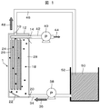
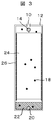
本発明の実施例1を図1から図7により説明する。図1は本実施例の固液分離処理システムの構成図、図2は、本発明の実施例1である固液分離処理装置の縦断面図、図3は図2の矢視A−A断面図、図4は実施例1の固液分離処理装置を上から見た平面図である。
A first embodiment of the present invention will be described with reference to FIGS. 1 is a configuration diagram of a solid-liquid separation processing system of the present embodiment, FIG. 2 is a longitudinal sectional view of a solid-liquid separation processing apparatus that is
原水50を貯留する原水タンク52と、固液分離処理装置1は原水用の配管34(原水配管34ともいう)で接続され、配管34の途中には循環用のポンプ38が設けられている。固液分離処理装置1に設けられた流出口10には濃縮水用の配管46(濃縮水配管46ともいう)が接続され、配管46は原水タンク52の液相中に浸漬されている。固液分離処理装置1に設けられたろ過水の流出口14にはろ過用の配管42(ろ過配管42ともいう)が接続され、配管42にはろ過用のポンプ40が設けられている。なお、循環用のポンプ38は、配管34の代わりに配管46に設けてもよい。
The
原水タンク52に貯留された原水50は、配管34の途中に設けられた循環用のポンプ38によって固液分離処理装置1の原水の流入口20へ送水される。濃縮水は、固液分離処理装置1の濃縮水の流出口10から配管46を経由して原水タンク52内の液相に循環される。固液分離処理装置1は後述するケーシング12で密閉されており、開口部として濃縮水の流出口10,ろ過水の流出口14,ろ過水の流出口14が設けられている。ろ過水は流出口14からポンプ40により取水でき、ポンプ40を稼動することにより清澄なろ過水を得ることができる。
The
このように構成しているので、ケーシング12内、配管34及び配管46の中には自由液面が存在しない状態を作ることが可能となる。配管34と配管46は原水タンク52内の原水50を介して液相が連続しているため、サイホンとして作用する。従って、循環ポンプ38の吐出圧力として水頭差は無視できる程小さく、配管抵抗および固液分離処理装置1内の流れの抵抗で吐出圧力が決定される。本実施例の固液分離処理システムは、このような構成しているので、循環用のポンプ38の動力を低減できるため、省コスト運転を実現することができる。
Since it comprises in this way, it becomes possible to make the state in which the free liquid level does not exist in the
固液分離処理装置1はケーシング12で長方体形状に形成され、ケーシング12の下部の側面に原水の流入口20が設けられ、ケーシング12内の流入口20に対向する位置に整流部22が設けられている。整流部22は、ケーシング12の底面に一端が固定され、他端がケーシング12の奥側の側面に固定され傾斜された平板で形成されている。整流部22は、図3に示すようにケーシング12間の幅で設けられ、少なくとも沈降性担体18が整流部22とケーシング12の間の空間に入らないようになっている。ケーシング12内の整流部22の上方には平膜モジュール24が複数個設置され、各平膜モジュール24は、流入口20から見て左右のケーシング12に設けられた平膜固定部26により固定されている。なお、整流部を上向流生成部ともいう。
The solid-liquid
平膜モジュール24の上部には、管状のろ過水の流出口14が設置され、各々の平膜モジュール24のろ過膜内部が流出口14と連通するように接続されている。流出口14は、ケーシング12を貫通して取り付けられ、ケーシング12に溶接等で固定されている。ケーシング12の上面には、濃縮水の流出口10が設けられている。ケーシング12内の平膜モジュール24の側方には、ケーシング12内を流動する沈降性担体18が下方に移動するための空間である沈降流路28が形成されている。沈降性担体18は、ケーシング12内に封入され平膜モジュール24間の距離よりも小さく形成され、平膜モジュール24間を自由に流れるようになっている。
Tubular filtered
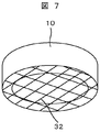
濃縮水の流出口10には、図6,図7に示すように、沈降性担体18よりも径が小さい担体分離用のメッシュ32が設けられている。ケーシング12内を流動する沈降性担体18は、平膜モジュール24の隙間を上昇した後に上向流の流速が一旦低下するため、その多くは沈降流路28に流れ込んで沈降する。
As shown in FIGS. 6 and 7, the concentrated
しかし、担体の比重,サイズ,表面性状,ケーシング12の上部構造によっては濃縮水の流出口10付近まで到達し、ケーシング12の外へ流出する可能性がある。図6で示すように、濃縮水の流出口10に、沈降性担体18よりも径が小さい担体分離用のメッシュ32を設けることで、確実に沈降性担体18を分離することができる。この結果、濃縮水に沈降性担体18が流出して配管やポンプの詰まりや故障を誘引する可能性や、沈降性担体18の個数が減少して洗浄効果が低減する可能性を無くすことができる。なお、下水処理水など繊維状物質を含んだ原水を固液分離する場合、このメッシュ32に繊維状物質が絡み付いて圧力損失を生じる可能性があるため、メッシュ32或いはメッシュ32を固定している部材は取り外しが可能で交換が容易な形状とすることが望ましい。また、この目詰まり量が外部から容易に分かるよう、ケーシング12には圧力計やマノメータなどを設け、内部圧力が明示されるようにすることが望ましい。
However, depending on the specific gravity, size, surface properties of the carrier, and the upper structure of the
処理対象の原水は、流入口20からケーシング12内に流入する。流入する原水には、慣性力が働いているためケーシング12の左側まで到達し、整流部22の傾斜によって上向きの流れとなる。ケーシング12の内部には、平膜モジュール24が平膜固定部26によって一定の間隔で固定されている。
The raw water to be treated flows into the
原水は、平膜モジュール24の隙間を通過して上方へ移動する。その際に、ケーシング12内に浮遊している、或いは底部に沈降している沈降性担体18を流動させる。上方へ移動した原水は濃縮水の流出口10から流出する。
The raw water moves upward through the gap of the
原水が平膜モジュール24の上端部を越えると、流路面積が拡大するため、上向流の流速が低下する。沈降性担体18は、後述するように、水より比重を大きく設定しているので、上方へ移動する速度が低下し、滞留して水平方向へ移動する。ケーシング12内には、流入した原水による上向流の影響を受けないように沈降流路28が設けられている。沈降性担体18は、沈降流路28を通過して重力により下方へ移動する。
When the raw water exceeds the upper end portion of the
下方に移動した沈降性担体18は、下方に設けられた原水の流入口20から流入する原水によって、再度流動させられて平膜モジュール24の隙間を通過して上方へ移動する。
The
一方、ろ過水の流出口14にはろ過用のポンプ40が接続されており、平膜モジュール24の内部を吸引ろ過してろ過水を得、流出口14からろ過水を取り出す。
On the other hand, a
気泡による平膜モジュール24の膜洗浄メカニズムの一つとして、上昇する気泡によって平膜モジュール24の膜面と並行にクロスフロー水流が発生し、活性汚泥の微生物やその生体外物質が付着し難くなる現象がある。
As one of the membrane cleaning mechanisms of the
本実施例は、原水の流入口20から流入する原水の運動エネルギーによって発生するクロスフロー水量で沈降性担体18を流動させ、膜面の付着物に沈降性担体18が衝突した際の衝突エネルギーにより付着物を剥離させる。
In this embodiment, the
一般に、水流によって流動する固体の有する運動エネルギーEは数1,数2で表される。
〔数1〕
E=(1/2)m・v2 …(1)
〔数2〕
m=ρ・V …(2)
ここで、mは固体の質量、vは固体の移動速度、ρは固体の比重、Vは固体の体積である。数1,数2から、固体の比重ρを大きくすれば固体の有する運動エネルギーEが増加することが分かる。すなわち、沈降性担体18の比重ρが大きいほど、沈降性担体18が流動して膜面付着物に衝突あるいは接触した際の剥離効果が高くなる。比重ρが大きいと沈降性が増大するため、上向きの水流が存在しない箇所において沈降性担体18はケーシング12の底部に向かって沈降する。底部には原水の流入口20が備えられているため、沈降した沈降性担体18は再度水流に同伴されて流動して平膜モジュール24の隙間を流れ、膜面の付着物を剥離させる。
In general, the kinetic energy E of the solid flowing by the water flow is expressed by
[Equation 1]
E = (1/2) m · v 2 (1)
[Equation 2]
m = ρ · V (2)
Here, m is the mass of the solid, v is the moving speed of the solid, ρ is the specific gravity of the solid, and V is the volume of the solid. From
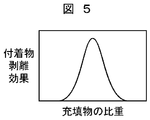
沈降性担体18の比重と付着物剥離効果の関係を図5に示す。沈降性担体18の比重が大きくなると、ある比重の沈降性担体18までは付着物の剥離効果は増大する。しかし、ある比重以上の沈降性担体18では、比重が大きくて重くなりすぎて流動性が低下し、整流部22によって生成される上向流に同伴されて流動する沈降性担体18の割合が減少し、全体として付着物剥離効果は低下する。検討した結果では、沈降性担体18の比重は1.2〜3.0の範囲が適切である。
FIG. 5 shows the relationship between the specific gravity of the
このように、流入する原水の運動エネルギーによって流動する沈降性担体18を用いることで、膜面の洗浄効果を増大することができる。その結果、従来の浸漬式の装置では必要であったエアスクラビングが不要となり、従来の加圧式膜モジュールにおいて1m/秒必要であった流速を低減できるため、省コスト運転が可能となる。
Thus, the cleaning effect of the membrane surface can be increased by using the
一般に、配管抵抗Rは、数3に示されるように、流速Vの二乗に比例する。
〔数3〕
R=k・V2 …(3)
この関係から、従来の加圧式膜モジュールで必要であった流速を半減できるので、加圧式膜モジュールのろ過抵抗を1/4にすることができる。水頭差を除くと、単純には循環ポンプの消費エネルギーを1/4とすることが可能となる。
In general, the pipe resistance R is proportional to the square of the flow velocity V as shown in Equation 3.
[Equation 3]
R = k · V 2 (3)
From this relationship, the flow rate required for the conventional pressure membrane module can be halved, so that the filtration resistance of the pressure membrane module can be reduced to ¼. Excluding the water head difference, the energy consumption of the circulation pump can be reduced to 1/4.
なお、本実施例では、図2に示すように原水の流入口20が1箇所の場合を説明したが、流入口20を複数個所に設けて、できるだけ全ての膜面で同じ流速が得られるようにすることが望ましい。
In addition, although the present Example demonstrated the case where the
また、図2には示していないが、上向流が確実に平膜モジュール24の隙間で発生するように、平膜モジュール24が設置されている側と沈降流路28の間に隔壁を設けることが望ましい。
Although not shown in FIG. 2, a partition is provided between the side where the
本実施例の固液分離処理装置を複数台並列して運転することで多量の固液分離処理が可能となる。その際に、施工や交換が容易となるように原水の流入口20,濃縮水の流出口10,ろ過水の流出口14は外部集水管が容易に脱着できるようアタッチメントにすることが望ましい。具体的には、差込式やねじ込み式の流入口や流出口とすることが望ましいが、通常利用されるフランジ接続でも良い。また、図2には示していないが、ケーシング12の底部には水抜き用のドレインを設けることが望ましい。また、沈降性担体18の取り出し用の孔あるいは口を設けておくことが実用上望ましい。
A large amount of solid-liquid separation processing can be performed by operating a plurality of solid-liquid separation processing apparatuses of this embodiment in parallel. At that time, it is desirable that the
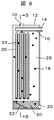
本発明の実施例2を図8,図9により説明する。図8は、本実施例の固液分離処理装置の縦断面図、図9は図8の矢視B−B断面図である。 A second embodiment of the present invention will be described with reference to FIGS. 8 is a longitudinal sectional view of the solid-liquid separation processing apparatus of the present embodiment, and FIG. 9 is a sectional view taken along the line BB in FIG.
本実施例は、実施例1と同様に構成されているが、本実施例では、図9に示すように、ケーシング12の下部に、沈降した沈降性担体18が原水の流入口20に向かう勾配を有する傾斜部30を備えている。
The present embodiment is configured in the same manner as in the first embodiment, but in this embodiment, as shown in FIG. 9, the
沈降性担体18は、沈降流路28を通過して傾斜部30の上に降下する。傾斜部30が無ければ、沈降性担体18はケーシング12内の隅の部分に蓄積すると、膜面洗浄に使われなくなる。その結果、膜面洗浄効果が減少し、沈降性担体18が蓄積した箇所に微生物が繁殖して腐敗するなど悪影響を及ぼすことになる。
The
本実施例では、傾斜部30を設けているので、沈降した沈降性担体18は重力によってより低い箇所へ向かって垂直方向および水平方向へ移動する。その移動する先に原水の流入口20が設けられているため、沈降性担体18は底部に蓄積することなく、ケーシング12内を循環することとなり、膜面の洗浄効率が向上する。また、沈降性担体18が蓄積しないため、腐敗などの問題も発生しない。
In this embodiment, since the
このように、ケーシング12の下部に、原水の流入口20へ向かう勾配を有する傾斜部30を設けることで、より膜面の洗浄効率を高めることができ、結果として原水の循環流量すなわち流速を低減でき、さらなる省コスト運転が可能となる。
Thus, by providing the
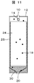
本発明の実施例3を図10,図11により説明する。図10は、本実施例の固液分離処理装置の縦断面図、図11は図10の矢視C−C断面図である。 A third embodiment of the present invention will be described with reference to FIGS. 10 is a longitudinal sectional view of the solid-liquid separation processing apparatus of the present embodiment, and FIG. 11 is a sectional view taken along the line CC in FIG.
本実施例は、実施例1と同様に構成されているが、本実施例では、図10に示すように、ケーシング12の底部に上向きの原水の流入口20を備え、整流部22の代わりに、沈降した沈降性担体18が原水の流入口20に向かう勾配を有する傾斜部30を備えている。なお、上向きの原水の流入口20を上向流生成部ともいう。
The present embodiment is configured in the same manner as in the first embodiment, but in this embodiment, as shown in FIG. 10, an upward
このようにすることで、ケーシング12内に効率よく上向流を発生することが可能となる。また、沈降した沈降性担体18が、傾斜部30に沿って原水の流入口20へ向かって移動し、流速の大きい流入口20から効率よく上向流に同伴されて上昇し、流動することとなるため、膜面の洗浄効果がより高くなる。なお、図10,図11では原水の流入口20が1箇所の場合を示したが、原水の流入口20を複数個所備え、できるだけ全ての膜面で均一な上向流速が得られるようにすることが望ましい。
By doing in this way, it becomes possible to generate an upward flow efficiently in the
このようにケーシング12の底部に原水の流入口20を備える場合、ケーシング12を床置きの状態で設置することはできないので、その場合にはケーシング12の下に脚部を設けることが必要となる。
When the
1 固液分離処理装置
10,14 流出口
12 ケーシング
16 集水管
18 沈降性担体
20 流入口
22 整流部
24 平膜モジュール
26 平膜固定部
28 沈降流路
30 傾斜部
32 メッシュ
34,42,46 配管
38,40 ポンプ
50 原水
52 原水タンク
DESCRIPTION OF
Claims (8)
Priority Applications (1)
| Application Number | Priority Date | Filing Date | Title |
|---|---|---|---|
| JP2007181621A JP4901614B2 (en) | 2007-07-11 | 2007-07-11 | Solid-liquid separation processing apparatus and solid-liquid separation processing system |
Applications Claiming Priority (1)
| Application Number | Priority Date | Filing Date | Title |
|---|---|---|---|
| JP2007181621A JP4901614B2 (en) | 2007-07-11 | 2007-07-11 | Solid-liquid separation processing apparatus and solid-liquid separation processing system |
Publications (2)
| Publication Number | Publication Date |
|---|---|
| JP2009018237A true JP2009018237A (en) | 2009-01-29 |
| JP4901614B2 JP4901614B2 (en) | 2012-03-21 |
Family
ID=40358349
Family Applications (1)
| Application Number | Title | Priority Date | Filing Date |
|---|---|---|---|
| JP2007181621A Expired - Fee Related JP4901614B2 (en) | 2007-07-11 | 2007-07-11 | Solid-liquid separation processing apparatus and solid-liquid separation processing system |
Country Status (1)
| Country | Link |
|---|---|
| JP (1) | JP4901614B2 (en) |
Cited By (2)
| Publication number | Priority date | Publication date | Assignee | Title |
|---|---|---|---|---|
| KR101068205B1 (en) * | 2011-03-04 | 2011-09-28 | 박병선 | Mbr tank assembly for decreasing fouling |
| CN103007754A (en) * | 2012-12-22 | 2013-04-03 | 郑州银科尔科技有限公司 | Multiphase homodromous flow membrane separation device and technology |
Citations (7)
| Publication number | Priority date | Publication date | Assignee | Title |
|---|---|---|---|---|
| JPS642567A (en) * | 1987-06-22 | 1989-01-06 | Kurita Water Ind Ltd | Bio-reactor |
| JPH04176327A (en) * | 1990-11-09 | 1992-06-24 | Ebara Infilco Co Ltd | Cleaning method for hollow fiber membrane filter device and hollow fiber membrane filter device |
| JPH08257581A (en) * | 1995-03-23 | 1996-10-08 | Kubota Corp | Immersion membrane separation apparatus utilizing float |
| JPH09136021A (en) * | 1995-11-14 | 1997-05-27 | Sumitomo Heavy Ind Ltd | Membrane filtering method and cleaning method for membrane separation device |
| JPH09201519A (en) * | 1996-01-29 | 1997-08-05 | Mitsubishi Kakoki Kaisha Ltd | Flat membrane separator |
| JPH11226572A (en) * | 1998-02-20 | 1999-08-24 | Kyowa Kako Kk | Immersion type membrane treatment system |
| JP2002361053A (en) * | 2001-06-12 | 2002-12-17 | Nisshinbo Ind Inc | Gel particle for cleaning separating membrane module, method of manufacturing for the same as well as cleaning method |
-
2007
- 2007-07-11 JP JP2007181621A patent/JP4901614B2/en not_active Expired - Fee Related
Patent Citations (7)
| Publication number | Priority date | Publication date | Assignee | Title |
|---|---|---|---|---|
| JPS642567A (en) * | 1987-06-22 | 1989-01-06 | Kurita Water Ind Ltd | Bio-reactor |
| JPH04176327A (en) * | 1990-11-09 | 1992-06-24 | Ebara Infilco Co Ltd | Cleaning method for hollow fiber membrane filter device and hollow fiber membrane filter device |
| JPH08257581A (en) * | 1995-03-23 | 1996-10-08 | Kubota Corp | Immersion membrane separation apparatus utilizing float |
| JPH09136021A (en) * | 1995-11-14 | 1997-05-27 | Sumitomo Heavy Ind Ltd | Membrane filtering method and cleaning method for membrane separation device |
| JPH09201519A (en) * | 1996-01-29 | 1997-08-05 | Mitsubishi Kakoki Kaisha Ltd | Flat membrane separator |
| JPH11226572A (en) * | 1998-02-20 | 1999-08-24 | Kyowa Kako Kk | Immersion type membrane treatment system |
| JP2002361053A (en) * | 2001-06-12 | 2002-12-17 | Nisshinbo Ind Inc | Gel particle for cleaning separating membrane module, method of manufacturing for the same as well as cleaning method |
Cited By (2)
| Publication number | Priority date | Publication date | Assignee | Title |
|---|---|---|---|---|
| KR101068205B1 (en) * | 2011-03-04 | 2011-09-28 | 박병선 | Mbr tank assembly for decreasing fouling |
| CN103007754A (en) * | 2012-12-22 | 2013-04-03 | 郑州银科尔科技有限公司 | Multiphase homodromous flow membrane separation device and technology |
Also Published As
| Publication number | Publication date |
|---|---|
| JP4901614B2 (en) | 2012-03-21 |
Similar Documents
| Publication | Publication Date | Title |
|---|---|---|
| JP2012528717A (en) | Membrane cleaning with pulsed gas slag and global aeration | |
| CN102036731B (en) | Rectangular sedimentation system having a self-aggregation facility | |
| JP2008221054A (en) | Drainage treatment apparatus and method | |
| JP2010158599A (en) | Spacing member, membrane element, and immersion type membrane separation apparatus | |
| CN205241332U (en) | Run by gravity membrane bioreactor | |
| WO2009006850A1 (en) | Hollow fiber membrane or capillary membrane filter and water filtration method using such a filter | |
| JP4901614B2 (en) | Solid-liquid separation processing apparatus and solid-liquid separation processing system | |
| CN209790958U (en) | Mud-water separation device for sewage treatment | |
| JP5787573B2 (en) | Gas-liquid separator | |
| JP4198299B2 (en) | Sewage treatment equipment | |
| JP3092013B2 (en) | Oil-water separator | |
| JP2008173556A (en) | Sewage treatment apparatus | |
| JP2011189308A (en) | Active-sludge treatment apparatus and operation method thereof | |
| JP5294555B2 (en) | Sewage treatment equipment | |
| JP2008142603A (en) | Sewage treatment device | |
| CN208429920U (en) | A kind of highly effective coagulation tube settler | |
| JP2018099646A (en) | Water treatment equipment | |
| JP2007268415A (en) | Immersion type membrane separation apparatus and water producing method | |
| KR101059956B1 (en) | Cleaner using ultrasonic wave and backflow of submerged flat membrane module for wastewater treatment | |
| JP6083688B2 (en) | Cross-flow sedimentation basin with a ceiling | |
| JP5825807B2 (en) | Waste water treatment apparatus and waste water treatment method | |
| KR100668420B1 (en) | Water cleanup device | |
| KR100945484B1 (en) | Water cleaning apparatus | |
| JP5899536B2 (en) | Inclination separator and separation method using the inclination separator | |
| JP2011050905A (en) | Apparatus for active treatment of sewage |
Legal Events
| Date | Code | Title | Description |
|---|---|---|---|
| A621 | Written request for application examination |
Free format text: JAPANESE INTERMEDIATE CODE: A621 Effective date: 20090729 |
|
| A977 | Report on retrieval |
Free format text: JAPANESE INTERMEDIATE CODE: A971007 Effective date: 20110127 |
|
| A131 | Notification of reasons for refusal |
Free format text: JAPANESE INTERMEDIATE CODE: A131 Effective date: 20110322 |
|
| A521 | Request for written amendment filed |
Free format text: JAPANESE INTERMEDIATE CODE: A523 Effective date: 20110616 |
|
| TRDD | Decision of grant or rejection written | ||
| A01 | Written decision to grant a patent or to grant a registration (utility model) |
Free format text: JAPANESE INTERMEDIATE CODE: A01 Effective date: 20111129 |
|
| A01 | Written decision to grant a patent or to grant a registration (utility model) |
Free format text: JAPANESE INTERMEDIATE CODE: A01 |
|
| A61 | First payment of annual fees (during grant procedure) |
Free format text: JAPANESE INTERMEDIATE CODE: A61 Effective date: 20111227 |
|
| R151 | Written notification of patent or utility model registration |
Ref document number: 4901614 Country of ref document: JP Free format text: JAPANESE INTERMEDIATE CODE: R151 |
|
| FPAY | Renewal fee payment (event date is renewal date of database) |
Free format text: PAYMENT UNTIL: 20150113 Year of fee payment: 3 |
|
| LAPS | Cancellation because of no payment of annual fees |