JP2009017613A - Controller, drive system, and heat transfer system - Google Patents
Controller, drive system, and heat transfer system Download PDFInfo
- Publication number
- JP2009017613A JP2009017613A JP2007173200A JP2007173200A JP2009017613A JP 2009017613 A JP2009017613 A JP 2009017613A JP 2007173200 A JP2007173200 A JP 2007173200A JP 2007173200 A JP2007173200 A JP 2007173200A JP 2009017613 A JP2009017613 A JP 2009017613A
- Authority
- JP
- Japan
- Prior art keywords
- power
- phase difference
- rotor
- mechanical angle
- generating
- Prior art date
- Legal status (The legal status is an assumption and is not a legal conclusion. Google has not performed a legal analysis and makes no representation as to the accuracy of the status listed.)
- Pending
Links
Images


Abstract
Description
本発明は、制御装置、駆動システム、および熱移動システムに関し、特に、トルク脈動を制御できる制御装置、駆動システム、および熱移動システムに関する。 The present invention relates to a control device, a drive system, and a heat transfer system, and more particularly, to a control device, a drive system, and a heat transfer system that can control torque pulsation.
近年、負荷変動を伴う負荷要素を駆動する同期モータの可変速制御にはインバータが用いられている。周期的な大きな負荷トルク変動を有するものとして、シングルロータリ型圧縮機あるいはレシプロ型圧縮機などが挙げられる。シングルロータリ型圧縮機あるいはレシプロ型圧縮機などは、空気調和機や冷蔵庫などの商品の圧縮機として広く使用されているものである。以下の説明では、これら圧縮機の呼称として、単にシングルロータリ型圧縮機として説明する。 In recent years, an inverter has been used for variable speed control of a synchronous motor that drives a load element accompanied by load fluctuation. A single rotary type compressor or a reciprocating type compressor may be mentioned as one having a large periodic load torque fluctuation. Single rotary compressors or reciprocating compressors are widely used as compressors for products such as air conditioners and refrigerators. In the following description, these compressors are simply referred to as single rotary compressors.
図9はシングルロータリ型圧縮機の特性を示す図である。図9において、実線はロータの機械角(ロータ表面上のある1点に着目したとき、その1点がどこを向いているかを、その向きと、所定の向きと、ロータの中心とでなす角度として示す値。)と負荷トルクとの関係を示す。粗い破線はロータ(モータの回転子)の機械角とモータトルクとの関係を示す。細かい破線はロータの機械角とロータの角速度との関係を示す。シングルロータリ型圧縮機の特徴は、構造が簡単で製造コストが安価であることと、負荷トルク変動が非常に大きいこととである。 FIG. 9 is a diagram showing the characteristics of a single rotary compressor. In FIG. 9, the solid line indicates the rotor mechanical angle (when one point on the rotor surface is noticed, the angle formed by the direction, the predetermined direction, and the center of the rotor indicates where the one point is directed. ) And the load torque. The rough broken line shows the relationship between the mechanical angle of the rotor (the rotor of the motor) and the motor torque. The fine broken line shows the relationship between the mechanical angle of the rotor and the angular velocity of the rotor. The characteristics of the single rotary type compressor are that the structure is simple and the manufacturing cost is low, and the load torque fluctuation is very large.
シングルロータリ型圧縮機は、冷媒の吸入、圧縮、吐出という圧縮サイクルをロータが1回転している間に順次繰返す。したがって、冷媒が圧縮されているので吐出直前は負荷トルクが大きくなり、冷媒が抜けているので吐出直後は負荷トルクが小さくなる。図9に示すようにモータトルクが一定であると、モータトルクと負荷トルクとの間に差が生じるので、ロータの角速度の変動と圧縮機の大きな振動とが生じる。これらはいずれもシングルロータリ型圧縮機を使用する場合に発生する課題である。 The single rotary type compressor sequentially repeats a compression cycle of refrigerant suction, compression, and discharge while the rotor is rotating once. Accordingly, since the refrigerant is compressed, the load torque is increased immediately before the discharge, and the load torque is decreased immediately after the discharge because the refrigerant is removed. As shown in FIG. 9, when the motor torque is constant, a difference is generated between the motor torque and the load torque, resulting in fluctuations in the angular velocity of the rotor and large vibrations in the compressor. These are all problems that arise when using a single rotary compressor.
これらの課題を解決するため、ロータの機械角に応じてモータトルクを変化させることが行われている。この対策により、吸入、圧縮、吐出のうちいずれであるかに応じてモータトルクを変化させることが可能となるので、負荷トルクの変動の影響の低減ひいては低圧縮機の振動化を図ることができる。 In order to solve these problems, the motor torque is changed according to the mechanical angle of the rotor. This measure makes it possible to change the motor torque depending on whether it is suction, compression, or discharge. Therefore, it is possible to reduce the influence of fluctuations in the load torque, and to reduce the vibration of the low compressor. .
そのような方法として、特許文献1〜5が知られている。
特許文献1は、4極の同期電動機と、インバータと、回転子位置検出回路と、回転速度検出回路と、トルクパターン記憶部と、機械的位置決定回路と、トルク制御部とを含む制御装置を開示する。4極の同期電動機は負荷を駆動する。インバータは、同期電動機に交流電力を供給する。回転子位置検出回路は、同期電動機の回転子の位置を検出する。回転速度検出回路は、回転子位置検出回路の出力により回転子の速度を算出する。トルクパターン記憶部は、同期電動機の1回転あたりの負荷トルクパターンを記憶する。機械的位置決定回路は、回転速度検出回路の出力により回転子の機械的位置を決定する。トルク制御部は、負荷トルクパターンに基づいて同期電動機の出力トルクを制御する。負荷トルクパターンは、回転子位置検出回路の出力と機械的位置決定回路の出力とに基づいてトルク制御部により選択される。
As such a method, Patent Documents 1 to 5 are known.
Patent Document 1 discloses a control device including a four-pole synchronous motor, an inverter, a rotor position detection circuit, a rotation speed detection circuit, a torque pattern storage unit, a mechanical position determination circuit, and a torque control unit. Disclose. A 4-pole synchronous motor drives a load. The inverter supplies AC power to the synchronous motor. The rotor position detection circuit detects the position of the rotor of the synchronous motor. The rotation speed detection circuit calculates the rotor speed based on the output of the rotor position detection circuit. The torque pattern storage unit stores a load torque pattern per rotation of the synchronous motor. The mechanical position determination circuit determines the mechanical position of the rotor based on the output of the rotation speed detection circuit. The torque control unit controls the output torque of the synchronous motor based on the load torque pattern. The load torque pattern is selected by the torque control unit based on the output of the rotor position detection circuit and the output of the mechanical position determination circuit.
特許文献1に開示された発明によると、圧縮機の振動検出器を必要としない安価な4極の同期電動機のトルク制御を実現できる。 According to the invention disclosed in Patent Document 1, it is possible to realize torque control of an inexpensive four-pole synchronous motor that does not require a compressor vibration detector.
特許文献2は、電動機と、インバータと、電流値を求める装置と、電動機の回転子位置を検出する装置と、トルク制御装置とを含む電動機のトルク制御装置を開示する。電動機は、周期的な負荷トルク変動を有する負荷要素を駆動する。インバータは、電動機を駆動する。電流値を求める装置は、電動機に流れる電流を検出して、d軸電流とq軸電流とを求める。d軸電流は、励磁電流成分である。q軸電流は、トルク電流成分である。電動機の回転子位置を検出する装置は、q軸電流の変動が負荷トルク変動に起因する周期性を有することを利用して電動機の回転子位置を検出する。トルク制御装置は、回転子位置情報を用いて周期的にd軸電流を変化させてトルク制御を行う。 Patent Document 2 discloses a torque control device for an electric motor including an electric motor, an inverter, a device for obtaining a current value, a device for detecting a rotor position of the electric motor, and a torque control device. The electric motor drives a load element having periodic load torque fluctuations. The inverter drives the electric motor. The device for obtaining the current value detects the current flowing through the electric motor and obtains the d-axis current and the q-axis current. The d-axis current is an exciting current component. The q-axis current is a torque current component. The apparatus for detecting the rotor position of the electric motor detects the rotor position of the electric motor by utilizing the fact that the fluctuation of the q-axis current has periodicity due to the load torque fluctuation. The torque control device performs torque control by periodically changing the d-axis current using the rotor position information.
特許文献2に開示された発明によると、新たな装置を付加することなく、振動を抑制できる。 According to the invention disclosed in Patent Document 2, vibration can be suppressed without adding a new device.
特許文献3は、1回転の負荷変動がある周期性を持つ圧縮機と、圧縮機の出力軸を駆動する機械角に対して電気角がm倍(mは2以上の整数)となるロータ極数が2×m極のブラシレスモータと、ブラシレスモータを駆動するためのインバータ電源と、ブラシレスモータの予め測定された負荷トルクの変動パターンに基づいたトルクパターンを記憶する記憶部と、ブラシレスモータの誘起電圧を検出してロータ位置を検出するロータ位置検出部と、ロータ位置検出部の位置検出信号に基づいてブラシレスモータの転流タイミングを決定し、目標速度と記憶手段に記憶されているトルクパターンに応じて印加電圧または電流を可変する制御部とを備えたトルク制御装置を開示する。ロータ位置検出部は、比較検出部と、機械角決定部とを含む。比較検出部は、ブラシレスモータの各相巻線を接続した仮想中性点から得られる基準電圧と複数極の磁石を有するロータが回転することで発生する各相誘起電圧とを比較してロータ位置情報を検出する。機械角決定部は、ロータの1回転を複数区間に分割して、区間毎に位置検出間隔Tnを検出し、インバータ電源の駆動信号パターンが同一となる電気角でπラジアン×m離れた区間同士の位置検出間隔のうち1組あるいは複数組の大小比較を行ない、その比較結果からロータの機械角を決定する。制御部は、ロータの機械角に適したトルクパターンのデータを記憶部から読み出し、このトルクパターンに基づいてブラシレスモータの印加電圧または電流を補正する。 Patent Document 3 discloses a compressor having a periodicity with a load fluctuation of one rotation, and a rotor pole whose electrical angle is m times (m is an integer of 2 or more) with respect to a mechanical angle that drives the output shaft of the compressor. Brushless motor having 2 × m poles, an inverter power source for driving the brushless motor, a storage unit for storing a torque pattern based on a pre-measured load torque variation pattern of the brushless motor, and induction of the brushless motor A rotor position detection unit that detects the rotor position by detecting the voltage, and determines the commutation timing of the brushless motor based on the position detection signal of the rotor position detection unit, and sets the target speed and the torque pattern stored in the storage means A torque control device including a control unit that varies the applied voltage or current accordingly is disclosed. The rotor position detection unit includes a comparison detection unit and a mechanical angle determination unit. The comparison detection unit compares the reference voltage obtained from the virtual neutral point where the phase windings of the brushless motor are connected with each phase induced voltage generated by the rotation of the rotor having a magnet with multiple poles, and the rotor position Detect information. The mechanical angle determination unit divides one rotation of the rotor into a plurality of sections, detects a position detection interval Tn for each section, and sections separated by π radians × m with an electrical angle at which the drive signal pattern of the inverter power supply is the same One or more sets of size detection intervals are compared, and the mechanical angle of the rotor is determined from the comparison result. The control unit reads torque pattern data suitable for the mechanical angle of the rotor from the storage unit, and corrects the applied voltage or current of the brushless motor based on the torque pattern.
特許文献3に開示された発明によると、速度差が小さい隣り合う位置検出間隔同士の速度の大小判定を行う必要がなく、速度差が大きくなるインバータ電源の駆動信号パターンが同一となる電気角でπラジアン×m(mは自然数)離れた区間同士の位置検出間隔の大小判定を行うため、容易かつ正確に機械を決定できる。 According to the invention disclosed in Patent Document 3, it is not necessary to determine the magnitude of the speed between adjacent position detection intervals with a small speed difference, and the drive signal pattern of the inverter power supply with the large speed difference has the same electrical angle. Since the position detection interval between sections separated by π radians × m (m is a natural number) is determined, the machine can be determined easily and accurately.
特許文献4は、複数相のコイルを備えた同期モータを制御するための制御装置を開示する。制御装置は、第1検出部と、第2検出部と、作成部と、通電部と、第1記憶部と、制御部とを含む。第1検出部は、複数相のうちのいずれかの特定相の電流を検出する。第2検出部は、電流の脈動に基づいて同期モータの回転子の機械角を検出する。作成部は、各相における、補正前の電圧データを各相について作成する。通電部は、複数のスイッチング素子を含み、制御データに基づいて、各スイッチング素子の導通を制御し、各コイルに通電する。第1記憶部は、第1の補正値を記憶する。第1の補正値は、機械角に対応した、電圧データを補正する値である。制御部は、通電部を制御する。制御部は、第1算出部と、第2算出部と、第3算出部とを含む。第1算出部は、特定相の電圧において、予め定められた位相を基準とした、同じ長さの期間における、特定相の電流の積算値同士の比率を算出する。第2算出部は、第2の補正値を算出する。第2の補正値は、第1算出部により算出された比率を目標の比率に制御するように電圧データを補正する値である。第3算出部は、各相の電圧データと第1の補正値と第2の補正値とに基づいて、各相についての制御データを算出する。 Patent Document 4 discloses a control device for controlling a synchronous motor including a plurality of phase coils. The control device includes a first detection unit, a second detection unit, a creation unit, an energization unit, a first storage unit, and a control unit. A 1st detection part detects the electric current of the specific phase in any one of several phases. The second detector detects the mechanical angle of the rotor of the synchronous motor based on the current pulsation. The creation unit creates voltage data before correction in each phase for each phase. The energization unit includes a plurality of switching elements, controls conduction of each switching element based on control data, and energizes each coil. The first storage unit stores the first correction value. The first correction value is a value for correcting the voltage data corresponding to the mechanical angle. The control unit controls the energization unit. The control unit includes a first calculation unit, a second calculation unit, and a third calculation unit. The first calculation unit calculates a ratio between the integrated values of the currents of the specific phase in a period of the same length with reference to a predetermined phase in the voltage of the specific phase. The second calculation unit calculates a second correction value. The second correction value is a value for correcting the voltage data so as to control the ratio calculated by the first calculation unit to the target ratio. The third calculation unit calculates control data for each phase based on the voltage data of each phase, the first correction value, and the second correction value.
特許文献4に開示された発明によると、ロータ位置を検知するセンサを用いずに、負荷トルクの変動が大きい負荷に接続されたモータを高い効率で制御できる。 According to the invention disclosed in Patent Document 4, a motor connected to a load having a large variation in load torque can be controlled with high efficiency without using a sensor for detecting the rotor position.
特許文献5は、直結された同期電動機により圧縮機を可変速駆動する電動圧縮機の制御装置を開示する。電動圧縮機の制御装置は、圧縮機の1回転角度範囲を複数の単位区間に分割し、1回転角度範囲における単位区間の通過所要時間を計測し、通過所要時間の長短比較により負荷トルク脈動位相を検出することを特徴とする。 Patent Document 5 discloses a control device for an electric compressor that drives a compressor at a variable speed by a directly connected synchronous motor. The control device for the electric compressor divides the one rotation angle range of the compressor into a plurality of unit sections, measures the time required for passing through the unit section in one rotation angle range, and compares the required time for passing through the load torque pulsation phase. Is detected.
特許文献5に開示された発明によると、直結された同期電動機によって駆動される圧縮機の振動と騒音を低減できる。
しかし、特許文献1に開示された発明では、次に述べる2つの問題点がある。第1の問題点は、非通電区間におけるトルク制御が行えないという問題点である。この問題点は、3相に対しそれぞれ120度通電するために生じる。3相に対しそれぞれ120度通電するのは、誘起電圧がゼロになる時期を検出してモータを駆動するためである。第2の問題点は、騒音が大きくなるという問題点である。騒音が大きくなるのは、120度通電のモータ電流の変化が正弦波通電に比べ急峻となるためである。 However, the invention disclosed in Patent Document 1 has the following two problems. A first problem is that torque control cannot be performed in a non-energized section. This problem arises because each of the three phases is energized 120 degrees. The reason why each of the three phases is energized 120 degrees is to detect the time when the induced voltage becomes zero and to drive the motor. The second problem is that noise increases. The reason for the increased noise is that the change in motor current with 120-degree conduction is steep compared to sine-wave conduction.
特許文献2に開示された発明では、制御装置が高価になるという問題点がある。制御装置が高価になるのは、複雑かつ高速な演算処理が必要となるためである。複雑かつ高速な演算処理が必要となるのは、複数のモータ電流を検出して座標変換を行い、d軸およびq軸電流を求めるためである。ただし、特許文献2に開示された発明においては、180度通電が可能である。 The invention disclosed in Patent Document 2 has a problem that the control device is expensive. The reason why the control device is expensive is that it requires complicated and high-speed arithmetic processing. The reason why complicated and high-speed arithmetic processing is required is to detect a plurality of motor currents, perform coordinate conversion, and obtain d-axis and q-axis currents. However, in the invention disclosed in Patent Document 2, energization at 180 degrees is possible.
特許文献3、4および5に開示された発明では、ロータの機械角を検出するため、インバータの出力側に様々な回路を設けなくてはならないという問題点がある。 In the inventions disclosed in Patent Documents 3, 4 and 5, there is a problem that various circuits must be provided on the output side of the inverter in order to detect the mechanical angle of the rotor.
本発明は上述の問題点を解決するためになされたものであって、その目的は、電流を検出するための制約が少なく、かつ簡易な演算処理によりロータの機械角に応じたトルク制御を実現できる制御装置を提供することにある。 The present invention has been made to solve the above-mentioned problems, and its purpose is to realize torque control according to the mechanical angle of the rotor by simple arithmetic processing with less restrictions for detecting the current. It is to provide a control device that can be used.
また、本発明の他の目的は、簡単な構成であっても容易に制御できる駆動システムおよび熱移動システムを提供することにある。 Another object of the present invention is to provide a drive system and a heat transfer system that can be easily controlled even with a simple configuration.
上記目的を達成するために、本発明のある局面に従うと、制御装置は、駆動システムに用いられる。駆動システムは、ロータを有する同期モータと、インバータと、測定装置と、制御装置とを含む。インバータは、直流電力の供給を受けて同期モータに交流電力を供給する。測定装置は、直流電力の電流値を測定する。制御装置は、直流電力の電流値に基づいてインバータを制御する。制御装置は、生成手段を含む。生成手段は、インバータに出力する制御信号を生成する。生成手段は、情報生成手段と、信号生成手段とを含む。情報生成手段は、電圧情報を生成する。電圧情報は、交流電力の電圧値を示す。信号生成手段は、電圧情報に応じた制御信号を生成する。制御装置は、出力手段と、受付手段とをさらに含む。出力手段は、インバータに制御信号を出力する。受付手段は、測定装置から、直流電力の電流値の入力を受付ける。生成手段は、推定手段と、位相差検出手段とをさらに含む。推定手段は、出力手段が制御信号を出力した後に受付手段が受付けた直流電力の電流値に基づいて、対象期間における交流電力の電流値を推定する。対象期間は、ロータが少なくとも1回転する期間である。位相差検出手段は、電圧情報が示す電圧値と推定手段が推定した電流値とに基づいて、交流位相差を検出する。交流位相差は、交流電力における電圧と電流との位相差である。制御装置は、記憶手段をさらに含む。記憶手段は、交流電力における電圧値と電流値とのうち予め定められた一方の電気角に対応付けて位相差検出手段が算出した交流位相差を記憶する。生成手段は、機械角判定手段をさらに含む。機械角判定手段は、電気角に対応するロータの機械角を交流位相差に基づいて判定する。信号生成手段は、制御信号を生成するための手段を含む。制御信号を生成するための手段は、機械角判定手段がロータの機械角を判定すると、ロータの機械角と電圧情報が示す電圧値とに応じた制御信号を生成する。 In order to achieve the above object, according to one aspect of the present invention, the control device is used in a drive system. The drive system includes a synchronous motor having a rotor, an inverter, a measuring device, and a control device. The inverter receives AC power and supplies AC power to the synchronous motor. The measuring device measures the current value of DC power. The control device controls the inverter based on the current value of the DC power. The control device includes generating means. The generating means generates a control signal output to the inverter. The generation unit includes an information generation unit and a signal generation unit. The information generating unit generates voltage information. The voltage information indicates the voltage value of AC power. The signal generator generates a control signal corresponding to the voltage information. The control device further includes an output unit and a reception unit. The output means outputs a control signal to the inverter. The accepting unit accepts an input of a current value of DC power from the measuring device. The generation means further includes an estimation means and a phase difference detection means. The estimating means estimates the current value of AC power in the target period based on the current value of DC power received by the receiving means after the output means outputs the control signal. The target period is a period during which the rotor rotates at least once. The phase difference detection means detects an AC phase difference based on the voltage value indicated by the voltage information and the current value estimated by the estimation means. The AC phase difference is a phase difference between voltage and current in AC power. The control device further includes storage means. The storage unit stores the AC phase difference calculated by the phase difference detection unit in association with one predetermined electrical angle of the voltage value and the current value in the AC power. The generation unit further includes a mechanical angle determination unit. The mechanical angle determining means determines the mechanical angle of the rotor corresponding to the electrical angle based on the AC phase difference. The signal generating means includes means for generating a control signal. The means for generating the control signal generates a control signal corresponding to the mechanical angle of the rotor and the voltage value indicated by the voltage information when the mechanical angle determining means determines the mechanical angle of the rotor.
本発明の他の局面に従うと、制御装置は、駆動システムに用いられる。駆動システムは、ロータを有する同期モータと、インバータと、測定装置と、制御装置とを含む。インバータは、直流電力の供給を受けて同期モータに交流電力を供給する。測定装置は、直流電力の電流値を測定する。制御装置は、直流電力の電流値に基づいてインバータを制御する。制御装置は、生成手段を含む。生成手段は、インバータに出力する制御信号を生成する。生成手段は、情報生成手段と、信号生成手段とを含む。情報生成手段は、電圧情報を生成する。電圧情報は、交流電力の電圧値を示す。信号生成手段は、電圧情報に応じた制御信号を生成する。制御装置は、出力手段と、受付手段とをさらに含む。出力手段は、インバータに制御信号を出力する。受付手段は、測定装置から、直流電力の電流値の入力を受付ける。生成手段は、推定手段と、位相差検出手段とをさらに含む。推定手段は、出力手段が制御信号を出力した後に受付手段が受付けた直流電力の電流値に基づいて、対象期間における交流電力の電流値を推定する。対象期間は、ロータが少なくとも1回転する期間である。位相差検出手段は、電圧情報が示す電圧値と推定手段が推定した電流値とに基づいて、交流位相差を検出する。交流位相差は、交流電力における電圧と電流との位相差である。制御装置は、記憶手段をさらに含む。記憶手段は、交流電力における電圧値の電気角に対応付けて位相差検出手段が算出した交流位相差を記憶する。生成手段は、電気角選択手段と、機械角選択手段とをさらに含む。電気角選択手段は、対象期間における少なくとも2種類の電気角を記憶手段が記憶した交流位相差に基づいて選択する。機械角選択手段は、予め定められた電気角と機械角との対応関係に基づいて特定される機械角の中から、電気角選択手段が選択した電気角それぞれに対応する交流位相差に基づいて、電気角選択手段が選択した電気角に対応するロータの機械角を選択する。信号生成手段は、制御信号を生成するための手段を含む。制御信号を生成するための手段は、機械角選択手段がロータの機械角を選択すると、ロータの機械角と電圧情報が示す電圧値とに応じた制御信号を生成する。 According to another aspect of the invention, the control device is used in a drive system. The drive system includes a synchronous motor having a rotor, an inverter, a measuring device, and a control device. The inverter receives AC power and supplies AC power to the synchronous motor. The measuring device measures the current value of DC power. The control device controls the inverter based on the current value of the DC power. The control device includes generating means. The generating means generates a control signal output to the inverter. The generation unit includes an information generation unit and a signal generation unit. The information generating unit generates voltage information. The voltage information indicates the voltage value of AC power. The signal generator generates a control signal corresponding to the voltage information. The control device further includes an output unit and a reception unit. The output means outputs a control signal to the inverter. The accepting unit accepts an input of a current value of DC power from the measuring device. The generation means further includes an estimation means and a phase difference detection means. The estimating means estimates the current value of AC power in the target period based on the current value of DC power received by the receiving means after the output means outputs the control signal. The target period is a period during which the rotor rotates at least once. The phase difference detection means detects an AC phase difference based on the voltage value indicated by the voltage information and the current value estimated by the estimation means. The AC phase difference is a phase difference between voltage and current in AC power. The control device further includes storage means. The storage means stores the AC phase difference calculated by the phase difference detection means in association with the electrical angle of the voltage value in AC power. The generation means further includes an electrical angle selection means and a mechanical angle selection means. The electrical angle selection means selects at least two types of electrical angles in the target period based on the AC phase difference stored in the storage means. The mechanical angle selecting means is based on the AC phase difference corresponding to each of the electrical angles selected by the electrical angle selecting means from among the mechanical angles specified based on the correspondence between the predetermined electrical angle and the mechanical angle. The mechanical angle of the rotor corresponding to the electrical angle selected by the electrical angle selection means is selected. The signal generating means includes means for generating a control signal. The means for generating the control signal generates a control signal according to the mechanical angle of the rotor and the voltage value indicated by the voltage information when the mechanical angle selecting means selects the mechanical angle of the rotor.
また、上述の対象期間は、ロータが複数回回転する期間であることが望ましい。併せて、機械角選択手段は、同一の電気角に対応する交流位相差の平均値同士の大小関係に基づいて、ロータの機械角を選択するための手段を含むことが望ましい。 Moreover, it is desirable that the above-described target period is a period in which the rotor rotates a plurality of times. In addition, it is desirable that the mechanical angle selection means includes means for selecting the mechanical angle of the rotor based on the magnitude relationship between the average values of the AC phase differences corresponding to the same electrical angle.
また、上述の同期モータは3相4極モータであることが望ましい。併せて、電気角選択手段は、対応選択手段を含むことが望ましい。対応選択手段は、位相差が2πラジアンである2種類の電気角を選択する。 The synchronous motor is preferably a three-phase four-pole motor. In addition, it is desirable that the electrical angle selection means includes correspondence selection means. The correspondence selection means selects two types of electrical angles having a phase difference of 2π radians.
もしくは、上述の対応選択手段は、位相差が2πラジアンである2種類の電気角のうち、記憶手段において対応付けられた交流位相差同士の差が最大になる電気角を選択するための手段を含むことが望ましい。 Alternatively, the correspondence selection unit described above is a unit for selecting an electrical angle that maximizes the difference between the AC phase differences associated in the storage unit among the two types of electrical angles having a phase difference of 2π radians. It is desirable to include.
また、上述の機械角選択手段は、対象期間における交流位相差の最大値と最小値との差が閾値を越えると、ロータの機械角を選択するための手段を含むことが望ましい。 The mechanical angle selection means described above preferably includes means for selecting the mechanical angle of the rotor when the difference between the maximum value and the minimum value of the AC phase difference in the target period exceeds a threshold value.
また、上述の記憶手段は、交流位相差に加え、補正値をロータの機械角に対応付けて予め記憶するための手段を含むことが望ましい。併せて、信号生成手段は、機械角選択手段が機械角を選択するまで、電圧情報に応じた制御信号を生成するための手段と、電圧情報が示す電圧値と記憶手段が記憶した補正値のうち機械角選択手段が選択した機械角に対応する値とに応じた制御信号を生成するための手段とを含むことが望ましい。 In addition to the AC phase difference, the storage unit described above preferably includes a unit for storing the correction value in advance in association with the mechanical angle of the rotor. At the same time, the signal generating means includes means for generating a control signal corresponding to the voltage information until the mechanical angle selecting means selects the mechanical angle, the voltage value indicated by the voltage information, and the correction value stored in the storage means. It is desirable to include means for generating a control signal corresponding to the value corresponding to the mechanical angle selected by the mechanical angle selection means.
本発明の他の局面にしたがうと、駆動システムは、ロータを有する同期モータと、インバータと、測定装置と、制御装置とを含む。インバータは、直流電力の供給を受けて同期モータに交流電力を供給する。測定装置は、直流電力の電流値を測定する。制御装置は、直流電力の電流値に基づいてインバータを制御する。制御装置は、生成手段を含む。生成手段は、インバータに出力する制御信号を生成する。生成手段は、情報生成手段と、信号生成手段とを含む。情報生成手段は、電圧情報を生成する。電圧情報は、交流電力の電圧値を示す。信号生成手段は、電圧情報に応じた制御信号を生成する。制御装置は、出力手段と、受付手段とをさらに含む。出力手段は、インバータに制御信号を出力する。受付手段は、測定装置から、直流電力の電流値の入力を受付ける。生成手段は、推定手段と、位相差検出手段とを含む。推定手段は、出力手段が制御信号を出力した後に受付手段が受付けた直流電力の電流値に基づいて、対象期間における交流電力の電流値を推定する。対象期間は、ロータが少なくとも1回転する期間である。位相差検出手段は、電圧情報が示す電圧値と推定手段が推定した電流値とに基づいて、交流位相差を検出する。交流位相差は、交流電力における電圧と電流との位相差である。制御装置は、記憶手段をさらに含む。記憶手段は、交流電力における電圧値の電気角に対応付けて位相差検出手段が算出した交流位相差を記憶する。前記生成手段は、機械角判定手段をさらに含む。機械角判定手段は、電気角に対応するロータの機械角を交流位相差に基づいて判定する。信号生成手段は、制御信号を生成するための手段を含む。制御信号を生成するための手段は、機械角判定手段がロータの機械角を判定すると、ロータの機械角と電圧情報が示す電圧値とに応じた制御信号を生成する。 According to another aspect of the present invention, the drive system includes a synchronous motor having a rotor, an inverter, a measuring device, and a control device. The inverter receives AC power and supplies AC power to the synchronous motor. The measuring device measures the current value of DC power. The control device controls the inverter based on the current value of the DC power. The control device includes generating means. The generating means generates a control signal output to the inverter. The generation unit includes an information generation unit and a signal generation unit. The information generating unit generates voltage information. The voltage information indicates the voltage value of AC power. The signal generator generates a control signal corresponding to the voltage information. The control device further includes an output unit and a reception unit. The output means outputs a control signal to the inverter. The accepting unit accepts an input of a current value of DC power from the measuring device. The generation unit includes an estimation unit and a phase difference detection unit. The estimating means estimates the current value of AC power in the target period based on the current value of DC power received by the receiving means after the output means outputs the control signal. The target period is a period during which the rotor rotates at least once. The phase difference detection means detects an AC phase difference based on the voltage value indicated by the voltage information and the current value estimated by the estimation means. The AC phase difference is a phase difference between voltage and current in AC power. The control device further includes storage means. The storage means stores the AC phase difference calculated by the phase difference detection means in association with the electrical angle of the voltage value in AC power. The generating unit further includes a mechanical angle determining unit. The mechanical angle determining means determines the mechanical angle of the rotor corresponding to the electrical angle based on the AC phase difference. The signal generating means includes means for generating a control signal. The means for generating the control signal generates a control signal corresponding to the mechanical angle of the rotor and the voltage value indicated by the voltage information when the mechanical angle determining means determines the mechanical angle of the rotor.
本発明の他の局面にしたがうと、熱移動システムは、圧縮機を有するヒートポンプと、ロータを有し、かつロータにより圧縮機を駆動する同期モータと、インバータと、測定装置と、制御装置とを含む。インバータは、直流電力の供給を受けて同期モータに交流電力を供給する。測定装置は、直流電力の電流値を測定する。制御装置は、直流電力の電流値に基づいてインバータを制御する。圧縮機は、1回転の負荷変動に周期性を有する。制御装置は、生成手段を含む。生成手段は、インバータに出力する制御信号を生成する。生成手段は、情報生成手段と、信号生成手段とを含む。情報生成手段は、電圧情報を生成する。電圧情報は、交流電力の電圧値を示す。信号生成手段は、電圧情報に応じた制御信号を生成する。制御装置は、出力手段と、受付手段とをさらに含む。出力手段は、インバータに制御信号を出力する。受付手段は、測定装置から、直流電力の電流値の入力を受付ける。生成手段は、推定手段と、位相差検出手段とを含む。推定手段は、出力手段が制御信号を出力した後に受付手段が受付けた直流電力の電流値に基づいて、対象期間における交流電力の電流値を推定する。対象期間は、ロータが少なくとも1回転する期間である。位相差検出手段は、電圧情報が示す電圧値と推定手段が推定した電流値とに基づいて、交流位相差を検出する。交流位相差は、交流電力における電圧と電流との位相差である。制御装置は、記憶手段をさらに含む。記憶手段は、交流電力における電圧値の電気角に対応付けて位相差検出手段が算出した交流位相差を記憶する。前記生成手段は、機械角判定手段をさらに含む。機械角判定手段は、電気角に対応するロータの機械角を交流位相差に基づいて判定する。信号生成手段は、制御信号を生成するための手段を含む。制御信号を生成するための手段は、機械角判定手段がロータの機械角を判定すると、ロータの機械角と電圧情報が示す電圧値とに応じた制御信号を生成する。 According to another aspect of the present invention, a heat transfer system includes a heat pump having a compressor, a synchronous motor having a rotor and driving the compressor by the rotor, an inverter, a measuring device, and a control device. Including. The inverter receives AC power and supplies AC power to the synchronous motor. The measuring device measures the current value of DC power. The control device controls the inverter based on the current value of the DC power. The compressor has a periodicity in a load fluctuation of one rotation. The control device includes generating means. The generating means generates a control signal output to the inverter. The generation unit includes an information generation unit and a signal generation unit. The information generating unit generates voltage information. The voltage information indicates the voltage value of AC power. The signal generator generates a control signal corresponding to the voltage information. The control device further includes an output unit and a reception unit. The output means outputs a control signal to the inverter. The accepting unit accepts an input of a current value of DC power from the measuring device. The generation unit includes an estimation unit and a phase difference detection unit. The estimating means estimates the current value of AC power in the target period based on the current value of DC power received by the receiving means after the output means outputs the control signal. The target period is a period during which the rotor rotates at least once. The phase difference detection means detects an AC phase difference based on the voltage value indicated by the voltage information and the current value estimated by the estimation means. The AC phase difference is a phase difference between voltage and current in AC power. The control device further includes storage means. The storage means stores the AC phase difference calculated by the phase difference detection means in association with the electrical angle of the voltage value in AC power. The generating unit further includes a mechanical angle determining unit. The mechanical angle determining means determines the mechanical angle of the rotor corresponding to the electrical angle based on the AC phase difference. The signal generating means includes means for generating a control signal. The means for generating the control signal generates a control signal corresponding to the mechanical angle of the rotor and the voltage value indicated by the voltage information when the mechanical angle determining means determines the mechanical angle of the rotor.
本発明に係る制御装置は、電流を検出するための制約が少なく、かつ簡易な演算処理によりロータの機械角に応じたトルク制御を実現できる。 The control device according to the present invention has few restrictions for detecting the current, and can realize torque control according to the mechanical angle of the rotor by simple arithmetic processing.
また、本発明に係る駆動システムおよび熱移動システムは、簡単な構成であっても容易に制御できる。 The drive system and the heat transfer system according to the present invention can be easily controlled even with a simple configuration.
以下、図面を参照しつつ、本発明の実施の形態について説明する。以下の説明では、同一の部品には同一の符号を付してある。それらの名称および機能も同一である。したがって、それらについての詳細な説明は繰返さない。 Hereinafter, embodiments of the present invention will be described with reference to the drawings. In the following description, the same parts are denoted by the same reference numerals. Their names and functions are also the same. Therefore, detailed description thereof will not be repeated.
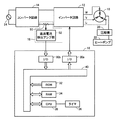
図1は、本実施の形態にかかる熱移動システムの構成を示す図である。本実施の形態にかかる熱移動システムは、冷凍庫の内部や室内の気温を制御する。図1を参照して、本実施の形態にかかる熱移動システムは、3相4極の同期モータ10と、インバータ回路12と、コンバータ回路14と、測定装置16と、制御装置18と、圧縮機20と、ヒートポンプ22とを含む。なお、本実施の形態にかかる熱移動システムのうち、同期モータ10と、インバータ回路12と、コンバータ回路14と、測定装置16と、制御装置18と、圧縮機20とは、ヒートポンプ22を駆動するための駆動システムを構成している。
FIG. 1 is a diagram illustrating a configuration of a heat transfer system according to the present embodiment. The heat transfer system according to the present embodiment controls the temperature inside the freezer and in the room. Referring to FIG. 1, a heat transfer system according to the present embodiment includes a three-phase four-pole
本実施の形態の場合、同期モータ10がインバータ回路12の出力側に接続されている。同期モータ10は、図示しないロータを有し、インバータ回路12が供給する交流電力によって動作する。インバータ回路12にはコンバータ回路14から直流電力が供給される。この直流電力は、交流電力から変換された電力である。その交流電力は、AC電源24から供給される。
In the present embodiment, the
インバータ回路12は、図示しない6個の半導体スイッチング素子が3相ブリッジ状に結線されている。なお、インバータ回路12には回生電流が流され、素子保護のために各々の半導体スイッチング素子に対して図示しないダイオードが並列接続されている。
In the
測定装置16は、インバータ回路12とコンバータ回路14との間に接続された電線(この電線は、コンバータ回路14が出力した直流電力をインバータ回路12に供給する。)の一方に流れる直流電流の大きさ(すなわち直流電流の電流値)を測定する。
The measuring
圧縮機20は、冷媒となる気体を圧縮する。本実施の形態の場合、圧縮機20はシングルロータリ型圧縮機である。圧縮機20がシングルロータリ型圧縮機なので、同期モータ10に供給される交流電力の任意の相における電圧と電流との位相差(本実施の形態の場合、この位相差を「交流位相差」と称する。)には周期的な変動が現れる。通常、シングルロータリ型圧縮機の負荷トルクは周期的に変動するためである。
The
ヒートポンプ22は、圧縮機20が圧縮した冷媒を用いて熱を移動させる。
測定装置16は、電流検出抵抗50と、直流電流検出アンプ部20とを含む。電流検出抵抗50は、インバータ回路12とコンバータ回路14との間に接続された電線の一方に設けられる。電流検出抵抗50の両端に発生する電圧に基づいて、直流電流検出アンプ部52は、インバータ回路12を流れる直流電流の大きさ(すなわち直流電流の電流値)を測定する。直流電流検出アンプ部52は、制御装置18に接続される。直流電流検出アンプ部52は、直流電流信号を制御装置18に出力する。直流電流信号は、直流電流検出アンプ部52が測定した直流電流の電流値を示す信号である。
The
The measuring
制御装置18は、インバータ回路12を制御する。制御装置18は、マイクロコンピュータによって実現される。制御装置18は、インバータ回路12に制御信号を出力するI/O(input/output)ポート30aと、直流電流信号の入力を測定装置16から受付けるI/Oポート30bと、ROM(Read Only Memory)32と、RAM(Random Access Memory)34と、タイマ36と、CPU(Central Processing Unit)38と、バス40とを含む。なお、以下の説明においては、I/Oポート30aとI/Oポート30bとを「I/Oポート30」と総称する。
The
ROM32は、CPU38が実行するプログラムなどを記憶する。ROM32が記憶したプログラムをCPU38が実行することにより、制御装置18は、本実施の形態にかかる発明を実現する装置となる。RAM34は、CPU38が利用するデータを一時的に記憶する。タイマ36は、時刻を測定する。CPU38は、制御装置18を構成する各部を制御する。また、CPU38は、各種の演算を行う。バス40は、制御装置18を構成する各部の間において情報を伝達する。
The
図2は、CPU38とROM32とRAM34とにより実現される生成部の機能ブロック図である。生成部は、インバータ回路12に出力する制御信号を生成する。
FIG. 2 is a functional block diagram of a generation unit realized by the
図2を参照して、生成部は、モータ電流推定部60と、位相差検出部62と、位相差情報記憶部64と、平均化部66と、目標位相差格納部68と、加算器70と、PI(Proportional Integral)演算部72と、ロータ機械的位置判定部74と、トルクパターン記憶部76と、乗算器78と、正弦波データテーブル80と、回転数設定部82と、正弦波データ作成部84と、PWM(Pulse Width Modulation control)作成部86とを含む。
Referring to FIG. 2, the generation unit includes a motor
モータ電流推定部60は、I/Oポート30aが制御信号を出力した後に、直流電流検出アンプ部52がI/Oポート30bに入力した直流電流信号(上述したように、これは、直流電力の電流値を示す)に基づいて、直流電流の変化量を求める。直流電流の変化量が求められると、モータ電流推定部60は、インバータ回路12の各駆動素子のスイッチングのタイミングに応じてその変化量を分配し、同期モータ10に供給される交流電力の各相の電流値を得る。直流電流の変化量を求めるための具体的な方法と各相の電流値を得るための具体的な方法とは、特開平8−19263号公報に記載されている。これにより、モータ電流推定部60は、PWM作成部86が信号を出力した後にI/O30bが受付けた直流電力の電流値に基づいて、対象期間(同期モータ10のロータが少なくとも1回転する期間)におけるインバータ回路12の出力側の電流値(すなわち、同期モータ10に供給される電流値)を各相について推定できる。同期モータ10に供給される電流値を各相について推定できるため、それらの電流値を測定するための電流センサ(コイルおよびホール素子で構成されたものやカレントトランスなどのモータ電流を検出するためのもの)は不要になる。電流センサが不要になるので、駆動システムひいては熱移動システムの生産コストを削減することができる。なお、モータ電流推定部60は、インバータ回路12の各駆動素子のスイッチングのタイミングを、PWM作成部86がPWM波形信号(これについては後述する。)をどの駆動素子に出力したかに基づいて検知する。
After the I / O port 30a outputs the control signal, the motor
位相差検出部62は、インバータ回路12が供給する交流電力の電圧(本実施の形態においては、これを「モータ電圧」と称する。)と電流(本実施の形態においては、これを「モータ電流」と称する。)との位相差すなわち交流位相差を検出し、交流位相差を示す位相差情報を出力する。位相差検出部62は、正弦波データ作成部84により信号として出力された電圧情報とモータ電流推定部60により信号として出力された電流情報とを用いて、交流位相差を検出する。交流位相差を検出するための方法には様々な方法があるが、本実施の形態においては、モータ電圧の値が「0」になった時点からモータ電流の値が「0」になった時点までの経過時間にモータ電圧の周波数と2πとを乗算することで、交流位相差を検出する。なお、同期モータ10の電圧情報は正弦波データ作成部84が作成するため、モータ電圧の値をセンサにより検出する必要はない。また、本実施の形態の場合、位相差情報は、モータ電圧の位相がモータ電流の位相に対して進んでいる場合は正の値を示し、遅れている場合は負の値を示し、同相の場合は「0」を示すこととする。
The phase difference detector 62 is a voltage of AC power supplied by the inverter circuit 12 (in this embodiment, this is referred to as “motor voltage”) and a current (in this embodiment, this is referred to as “motor current”. And the phase difference information indicating the AC phase difference is output. The phase difference detection unit 62 detects an AC phase difference using the voltage information output as a signal by the sine wave
なお、上述した方法で交流位相差を検出する場合、位相差検出部62は、モータ電圧の電気角が360度(2πラジアン)変化する間に2回、交流位相差を検出することができる。交流電力の1相において、電気角が360度(2πラジアン)変化する間のゼロクロス点(値が「0」となる位相)には0度(0ラジアン)と180度(πラジアン)との2種類が存在するためである。そのように交流位相差を検出することができるため、同期モータ10が3相4極同期モータである場合、1相あたり4回交流位相差を検出することができる。同期モータ10の1回転は電気角が720度(4πラジアン)変化することに相当するためである。1相あたり4回交流位相差を検出することができるため、3相分について位相差検出部62が交流位相差を検出できる回数は12回である。このため、位相差検出部62は、同期モータ10の1回転を12分割した区間(すなわち、ロータの機械角が2π/12=π/6ラジアン変化する区間)毎に交流位相差を検出し、位相差情報を出力する。
When the AC phase difference is detected by the above-described method, the phase difference detection unit 62 can detect the AC phase difference twice while the electrical angle of the motor voltage changes by 360 degrees (2π radians). In one phase of AC power, the zero crossing point (phase where the value becomes “0”) while the electrical angle changes 360 degrees (2π radians) is 0 degrees (0 radians) and 180 degrees (π radians). This is because there are types. Since the AC phase difference can be detected as described above, when the
なお、本実施の形態において、「電気角」とは、電圧や電流の位相を角度で示したものである。本実施の形態においては、位相が一巡して元の位相に戻ったとき、電気角が2πラジアン変化したとみなす。 In the present embodiment, the “electrical angle” refers to the phase of voltage or current as an angle. In the present embodiment, it is considered that the electrical angle has changed by 2π radians when the phase makes a round and returns to the original phase.
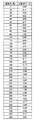
位相差情報記憶部64は、位相差検出部62が出力した位相差情報を記憶する。図3は、本実施の形態における、位相差情報記憶部64が記憶した同期モータ10の1回転における位相差情報の一例を示す概念図である。
The phase difference
図3を参照して、本実施の形態における位相差情報は、電気角を示す情報と、機械角を示す情報と、位相差を示す情報と、補足を示す情報とを含む。これらの情報は対応付けられている。 With reference to FIG. 3, the phase difference information in the present embodiment includes information indicating an electrical angle, information indicating a mechanical angle, information indicating a phase difference, and information indicating a supplement. These pieces of information are associated with each other.
電気角を示す情報は、次に述べる2種類の位相のうち一方を示す。第1種類目は、モータ電圧のゼロクロス点を基準としたモータ電圧の同期モータ10における位相である。第2種類目は、モータ電流のゼロクロス点を基準としたモータ電流の同期モータ10における位相である。電気角を示す情報がこれらの位相のうちいずれを示すかは制御装置18の設計者が定める。
The information indicating the electrical angle indicates one of the following two types of phases. The first type is a phase of the motor voltage in the
機械角を示す情報は、同期モータ10が有するロータの機械角を示す。
補足を示す情報は、どの相についての電圧と電流との位相差を「位相差を示す情報」が示しているかを示す。
The information indicating the mechanical angle indicates the mechanical angle of the rotor included in the
The information indicating the supplement indicates whether the phase difference between the voltage and current for which phase indicates “information indicating the phase difference”.
再び図2を参照して、平均化部66は、位相差情報が示すロータ1回転分の交流位相差の平均値を算出し、その平均値を加算器70に出力する。
Referring again to FIG. 2, averaging
目標位相差格納部68は、目標として予め設定された交流位相差を示す情報を格納する。この位相差(以下、「目標位相差」と称する)は、同期モータ10を高効率駆動するように制御装置18の設計者などによって予め決定されている。決定のための具体的な方法の例には、実験やシミュレーションなどがある。
The target phase
加算器70は、平均化部66が算出した位相差の平均値と目標位相差との差を算出する。本実施の形態においては、この差を「位相差誤差量」と称する。
The
PI演算部72は、加算器70により算出された位相差誤差量に基づいて比例誤差(P)および積分誤差(I)を算出し、それらを示すPI制御信号を乗算器78に出力する。
ロータ機械的位置判定部74は、同期モータ10のロータの機械角を特定し、その機械角を示す情報をトルクパターン記憶部76に出力する。ロータ機械的位置判定部74は、同期モータ10のロータが1回転する間における位相差の脈動と上述した電気角(すなわち、モータ電圧の位相を示す電気角とモータ電流の位相を示す電気角とのうち予め定められた一方)とに基づいてロータの機械角を特定する。位相差の脈動は、位相差情報格納部30に格納されている位相差情報に基づいて検出される。
The rotor mechanical
図4を参照して、ロータ機械的位置判定部74の動作について具体的に説明する。図4は、本実施の形態に係る同期モータ10に加わる負荷トルクの推移と、モータ電圧の推移と、モータ電流の推移と、電気角の推移と、機械角の推移とを示す図である。なお、図4においては、「U相モータ電圧とU相モータ電流」欄の実線がU相におけるモータ電圧を示す。粗い破線がU相におけるモータ電流を示す。電圧のゼロクロス点と電流のゼロクロス点との間に付された矢印が交流位相差を示す。
The operation of the rotor mechanical
同期モータの構造上、機械角と電気角とは対応している(モータ電圧の電気角であってもモータ電流の電気角であっても同様である)。たとえば、本実施の形態における同期モータ10は4極同期モータである。4極同期モータでは、機械角が360度(2πラジアン)変化する間に電気角は720度(4πラジアン)変化する。これにより、同期モータ10のロータの機械角が定められると、それに対応する電気角は、0度(0ラジアン)から360度(2πラジアン)までの1つあるいは360度(2πラジアン)から720度(4πラジアン)までの1つになる。
The mechanical angle and the electrical angle correspond to each other in the structure of the synchronous motor (the same applies to the electrical angle of the motor voltage and the electrical angle of the motor current). For example, the
そのようになるので、4極同期モータを制御する場合、図4に示した区間Sの範囲に電気角が含まれるのか、それとも図4に示した区間Tの範囲に電気角が含まれるのかの判別さえできれば、ロータの機械角を判定できる。 As a result, when controlling a 4-pole synchronous motor, whether an electrical angle is included in the range of the section S shown in FIG. 4 or an electrical angle is included in the range of the section T shown in FIG. If it can be determined, the mechanical angle of the rotor can be determined.
一方、シングルロータリ型圧縮機のような周期的なトルク変動を有する負荷に同期モータ10が接続されている場合、同一の相における交流位相差は、ロータの機械角に対応する。
On the other hand, when the
交流位相差がロータの機械角に対応し、かつ交流位相差と電気角とは位相差情報として対応付けられているので、位相差情報格納部30に記憶されている位相差情報に基づき、同位相の電気角に対応する交流位相差同士を比較し、その結果に応じて電気角と機械角とを対応付けると、電気角に基づいて機械角を特定することが可能になる。例えば、4極同期モータの場合、電気角0度(0ラジアン)に対応する交流位相差(図3では40度すなわちπ/9ラジアン)と電気角360度(2πラジアン)に対応する交流位相差と(図3では10度すなわちπ/36ラジアン)を比較し、大きい位相差に対応する電気角(0ラジアン)を機械角0度(0ラジアン)に対応付け、小さい位相差に対応する電気角(2πラジアン)を機械角180度(πラジアン)に対応付けると、これらの対応関係と、予め知られている機械角と電気角との関係とに基づいて、任意の電気角に対応する機械角を特定できる。ロータ機械的位置判定部74は、これらの処理を行うことにより、ロータの機械角を検出する。
Since the AC phase difference corresponds to the mechanical angle of the rotor, and the AC phase difference and the electrical angle are associated as phase difference information, based on the phase difference information stored in the phase difference
これらの処理を実施するため、ロータ機械的位置判定部74は、電気角選択部90と、機械角選択部92とを含む。
In order to perform these processes, the rotor mechanical
電気角選択部90は、ロータが1回転する期間における2種類の電気角を選択する。これらの電気角は、位相差情報格納部30が記憶した交流位相差に基づいて選択される。本実施の形態の場合、電気角選択部90は、電気角同士の位相差が2πラジアンとなる2種類の電気角のうち、交流位相差同士の差が最大になる組合せを選択する。対応付けに対する信頼性が向上するためである。
The electrical
機械角選択部92は、電気角選択部90が選択した電気角それぞれに対応する交流位相差と制御装置18の設計者により予め定められた規則とに基づいて、それらの電気角に対応するロータの機械角を選択する。これにより機械角と電気角とが対応付けられる。制御装置18の設計者は、任意の規則を対応付けのための規則として採用できる。たとえば、同期モータ104極同期モータであれば、上述したように、大きい交流位相差に対応する電気角(0ラジアン)を機械角0度(0ラジアン)に対応付け、小さい交流位相差に対応する電気角(2πラジアン)を機械角180度(πラジアン)に対応付けてもよい。
The mechanical
いったん対応付けが行われると、同期モータ10への電力の供給を停止するまで、機械角選択部92は、正弦波データ作成部84が出力した電圧情報に基づいて電気角を算出し、算出された電気角と機械角選択部90が行った対応付けとに基づいてロータの機械角を算出する。機械角を算出するための方法は特に限定されるものではないが、たとえば、機械角選択部90が対応付けを行った電気角と電圧情報に基づいて算出した電気角との位相差を算出し、その位相差を機械角の位相差(機械角が1ラジアン変化したとき電気角が何ラジアン変化するかは予め定められていることとする)に換算し、換算により得られた値を機械角選択部90が電気角と対応付けた機械角に加算するという方法がある。
Once the association is performed, the mechanical
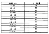
トルクパターン記憶部76は、トルク補正量を記憶する。トルク補正量は、ロータの機械角の範囲に対応付けられている。トルクパターン記憶部76は、自らが記憶したトルク補正量のうちロータ機械的位置判定部74が算出した機械角に応じたトルク補正量を乗算器78に出力する。図5は、本実施の形態における、トルクパターン記憶部76に記憶されたトルク補正量の一例を示す概念図である。
The torque
乗算器78は、PI演算部72からのPI制御信号が示す値とトルクパターン記憶部76からのトルク補正量とに基づいて算出された値(デューティ基準値)をPWM作成部86に出力する。
正弦波データテーブル80は、所定のデータの組合せとして構成された正弦波データを予め記憶する。図6は、本実施の形態において正弦波データテーブル80に記憶される正弦波データを示す概念図である。本実施の形態においては、正弦波データは、電気角に対応付けられている。正弦波データテーブル80は、正弦波データ作成部84に正弦波データを出力する。
The sine wave data table 80 stores sine wave data configured as a combination of predetermined data in advance. FIG. 6 is a conceptual diagram showing sine wave data stored in the sine wave data table 80 in the present embodiment. In the present embodiment, the sine wave data is associated with the electrical angle. The sine wave data table 80 outputs sine wave data to the sine wave
回転数設定部82は、ROM32に記憶されたプログラムに基づき、強制励磁周波数を選択し、正弦波データ作成部84に出力する。回転数設定部82が選択する強制励磁周波数は、回転数指令値に対応する。
The rotation
正弦波データ作成部84は、正弦波データテーブル80が記憶した正弦波データを読出す。正弦波データ作成部84は、回転数設定部82が選択した強制励磁周波数に基づいて、同期モータ10のU相,V相,およびW相に対応するように、読出す正弦波データを選択する。正弦波データ作成部84は、読出した正弦波データをPWM作成部86に出力する。また、正弦波データ作成部84は、同期モータ10のU相,V相,およびW相に対応した正弦波データ(すなわち、正弦波データテーブル80から読出した正弦波データ)からU相,V相,およびW相の電圧値を示す電圧情報を作成し、位相差検出部62に出力する。
The sine wave
PWM作成部86は、モータ電圧を示すPWM波形信号(パルスの集合体)を生成し、インバータ回路12の各駆動素子(上述したように、本実施の形態の場合、これらは図示しない6個の半導体スイッチング素子である。これらが動作することで、同期モータ10のU相,V相,およびW相の交流電力が生成される。)にそれを出力する。本実施の形態の場合、PWM作成部86は、正弦波データとデューティー基準値とからデューティー比をいったん算出し、算出されたデューティー比に基づいてPWM波形信号を生成する。インバータ回路12がそのPWM波形信号に基づいて同期モータ10の巻線に電圧を印加することで(すなわち、インバータ回路12の各駆動素子がPWM波形信号に応じてONになったりOFFになったりすることで)同期モータ10が駆動される。この時、インバータ回路12が供給する交流電力の電圧はPWM波形信号のデューティー比に対応している。
The
本実施の形態の場合、PWM作成部86は、初期生成部94と、一般生成部96とを含む。
In the case of the present embodiment, the
初期生成部94は、機械角選択部92が機械角と電気角との対応付けを行うまで、電圧情報に応じたPWM波形信号を生成する。
The initial generation unit 94 generates a PWM waveform signal corresponding to the voltage information until the mechanical
一般生成部96は、電圧情報が示す電圧値とトルクパターン記憶部76が出力したトルク補正量とに応じたPWM波形信号を生成する。
The
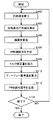
図7を参照して、以上のような構造に基づく、制御装置18の動作について説明する。
正弦波データテーブル80は、正弦波データ作成部84に正弦波データを出力する。正弦波データ作成部84は、同期モータ10のU相,V相,およびW相に対応した正弦波データからU相,V相,およびW相の電圧についての電圧情報を作成し、位相差検出部62とPWM作成部86とに出力する。PWM作成部86の初期生成部94は、電圧情報に応じたPWM波形信号を生成する。PWM波形信号は、I/O30aを介してインバータ回路12に出力される。インバータ回路12は、PWM波形信号に応じて交流電力を同期モータ10に供給する。測定装置16は、インバータ回路12にこの時供給される直流電流の値を測定する。
With reference to FIG. 7, the operation of the
The sine wave data table 80 outputs sine wave data to the sine wave
モータ電流推定部60は、測定装置16の直流電流検出アンプ部52が入力した直流電流信号に基づいて同期モータ10に供給される交流電力の各相の電流値を得、その電流量を示す電流情報を生成する。同期モータ10のロータが少なくとも1回転する期間分の電流情報が生成される。位相差検出部62は、正弦波データ作成部84により出力された電圧情報とモータ電流推定部60により出力された電流情報とを用いてモータ電圧とモータ電流との交流位相差を検出し、位相差情報を作成し、出力する。出力された位相差情報は位相差情報記憶部64が記憶する。位相差情報が記憶されると、ロータ機械的位置判定部74による機械角と電気角との対応付けが行われる(ステップS100)。
The motor
対応付けが行われると、平均化部66は、機械角が360度(2πラジアン)変化する期間における交流位相差の平均値を算出し、その平均値を加算器70に出力する(ステップS102)。
When the association is performed, the averaging
平均値が出力されると、加算器70は誤差を算出する(ステップS104)。
誤差が算出されると、PI演算部72は、加算器70により算出された誤差に基づいて比例誤差(P)および積分誤差(I)を算出し、それらを示すPI制御信号を乗算器78に出力する(ステップS106)。
When the average value is output, the
When the error is calculated, the
一方、ロータ機械的位置判定部74は、同期モータ10のロータの機械角を算出し、その機械角を示す情報をトルクパターン記憶部76に出力する。トルクパターン記憶部76は、自らが記憶したトルク補正量のうちロータ機械的位置判定部74が特定した機械角に応じたトルク補正量を乗算器78に出力する(ステップS108)。
On the other hand, the rotor mechanical
トルク補正量が出力されると、乗算器78はデューティー基準値をPWM作成部86に出力する(ステップS110)。デューティー基準値が出力されると、PWM作成部86は、PWM波形信号を生成し、インバータ回路12の各駆動素子にそれを出力する。インバータ回路12は、そのPWM波形信号に基づいて同期モータ10の巻線に電圧を印加する(ステップS112)。
When the torque correction amount is output, the
その後、CPU38は、同期モータ10の制御を終了するか否かを判断する(ステップS114)。同期モータ10の制御を終了する場合(ステップS114にてYES)、処理は終了する。もしそうでないと(ステップS114にてNO)、処理はステップS100へと移される。
Thereafter, the
以上のようにして、本実施の形態にかかる制御装置18は、交流位相差に基づいて電気角と機械角とを1対1に対応付けた後、電気角に基づいて同期モータ10のトルクの補正値を選択し、その補正値に応じたトルクで同期モータ10のロータを回転させる。これにより、予め実験により測定したロータの機械角と負荷トルクとの関係に基づき、ロータの機械角に応じたトルク制御を実現できる。そのための処理はごく簡単である。
As described above, the
しかも、本実施の形態にかかる制御装置18は、上述したようにして同期モータ10のロータを回転させるので、180度通電が可能である。180度通電が可能なので、電流を検出するための制約が少ない。
Moreover, since the
また、180度通電が可能なので、本実施の形態にかかる駆動システムは、電流を検出するための制約が少ない。 Moreover, since 180 degree | times conduction is possible, the drive system concerning this Embodiment has few restrictions for detecting an electric current.
また、電気角が同一のときのロータの機械角(機械角の位相はπラジアン異なる)の判別を行なうので、機械角と記憶させていたトルク補正値との対応が狂ってしまう危険性がない。 Further, since the mechanical angle of the rotor when the electrical angle is the same (the phase of the mechanical angle is different by π radians) is determined, there is no risk that the correspondence between the mechanical angle and the stored torque correction value will be out of order. .
冷凍・空調装置などで使用される圧縮機20の内部は高温になる。その内部が高温になるので、圧縮機20にホールICなどの位置センサ(ロータ位置を検出するもの)を設けることは困難である。位置センサを設けることが困難なため、位置センサレスで同期モータ10を駆動する必要がある。そこで、上述した制御装置18を使用すると、位置センサは不要となる。そして、このモータ制御装置を備えた圧縮機駆動装置を冷凍・空調装置に搭載すると、冷蔵庫、冷凍庫、空気調和機といった冷凍・空調装置を位置センサなしに運転することが可能となる。また、交流電流を検出するための電流センサ(コイルおよびホール素子で構成された電流センサやカレントトランス)が不要となる。
The inside of the
なお、本実施の形態の第1の変形例において、ロータ機械的位置判定部74は、電気角0度に対応付けられた2つの位相差(図3では、位相差40度と10度)の比較に加え、電気角60度に対応付けられた2つの位相差(図3では、位相差35度と15度)を比較し、かつ、電気角120度に対応付けられた2つの位相差(図3では、位相差30度と20度)を比較して、ロータの機械角と電気角との対応付けを行ってもよい。対応付けのための規則が任意であることは上述した実施例と同様である。多くの電気角についての比較に基づき機械角と電気角との対応付けを行うことで、その対応付けに誤りが生じる可能性が低下する。
In the first modification of the present embodiment, the rotor mechanical
また、本実施の形態の第2の変形例において、ロータ機械的位置判定部74は、機械角が360度(2πラジアン)変化する間における交流位相差の変動が閾値を越えるとき、機械角と電気角との対応付けおよび機械角の出力を行ってもよい。圧縮機20の負荷トルクが十分大きくなっていない運転状態においては、交流位相差の変動が小さいこともある。このような状態で機械角と電気角との対応付けを行うと誤った対応付けが行われる危険がある。これを防止し、信頼性を向上させるためである。閾値の具体的な値は特に限定されない。たとえば、10度(π/18ラジアン)であってもよい。
In the second modification of the present embodiment, the rotor mechanical
また、本実施の形態の第3の変形例において、ロータ機械的位置判定部74は、同一の電気角に対応する交流位相差の平均値を用いて機械角と電気角との対応付けを行ってもよい。図8は、本変形例にかかる位相差情報の概念図である。図8に示す位相差情報は、最後に算出された交流位相差(図8においては「今回」と記載された欄の位相差)と、3回転前までの交流位相差と、それらの平均値(すなわち、最後に算出された交流位相差から3回転前の交流位相差までの平均値)とを含む。ロータ機械的位置判定部74は、その平均値を用いて機械角と電気角との対応付けを行うことができる。これにより、機械角と電気角との対応付けを行う際のノイズの影響を除去できる。
In the third modification of the present embodiment, the rotor mechanical
また、本実施の形態にかかる駆動システムは、冷凍・空調装置などで使用される熱移動システムに適用されているが、本実施の形態の第4の変形例においては、本実施の形態にかかる駆動システムをその他の負荷に接続しても良い。同期モータ10の回転に同期した所定周期の脈動を負荷が有するとき、本実施の形態にかかる駆動システムは、高効率で安定した駆動を実現することができる。
In addition, the drive system according to the present embodiment is applied to a heat transfer system used in a refrigeration / air conditioner or the like, but the fourth modification of the present embodiment is related to the present embodiment. The drive system may be connected to other loads. When the load has a pulsation with a predetermined period synchronized with the rotation of the
また、本実施の形態の第5の変形例において、同期モータ10は、3相4極の同期モータでなくてもよい。この場合、ロータの機械角が定められると、それに対応する電気角の数は、極数に応じて変化する。たとえば、同期モータが3相8極のとき、ある機械角に対応する電気角は、0度(0ラジアン)から360度(2πラジアン)までの1つと、360度(2πラジアン)から720度(4πラジアン)までの1つと、720度(4πラジアン)から1080度(6πラジアン)までの1つと、1080度(6πラジアン)から1440度(8πラジアン)までの1つとになる。電気角の数が極数に応じて変化するので、ロータ機械的位置判定部74が比較する交流位相差の数は、同期モータの極数に応じて変化する。それが変化したときにも交流位相差はロータの機械角に対応するので、交流位相差同士の大小関係に基づいた機械角と電気角との対応付けは可能である。
In the fifth modification of the present embodiment, the
また、本実施の形態の第6の変形例において、PWM波形信号の生成は、正弦波データテーブル80が出力した正弦波データを元とする生成に限られない。たとえば、PWM波形信号は、演算によって生成されても構わない。 In the sixth modification of the present embodiment, the generation of the PWM waveform signal is not limited to the generation based on the sine wave data output from the sine wave data table 80. For example, the PWM waveform signal may be generated by calculation.
今回開示された実施の形態はすべての点で例示であって制限的なものではないと考えられるべきである。本発明の範囲は上記した説明ではなくて特許請求の範囲によって示され、特許請求の範囲と均等の意味および範囲内でのすべての変更が含まれることが意図される。 The embodiment disclosed this time should be considered as illustrative in all points and not restrictive. The scope of the present invention is defined by the terms of the claims, rather than the description above, and is intended to include any modifications within the scope and meaning equivalent to the terms of the claims.
10 同期モータ、12 インバータ回路、14 コンバータ回路、16 測定装置、18 制御装置、24 AC電源、30 I/Oポート、32 ROM、34 RAM、36 タイマ、38 CPU、40 バス、50 電流検出抵抗、52 直流電流検出アンプ部、60 モータ電流推定部、62 位相差検出部、64 位相差情報記憶部、66 平均化部、68 目標位相差格納部、70 加算器、72 PI演算部、74 ロータ機械的位置判定部、76 トルクパターン記憶部、78 乗算器、80 正弦波データテーブル、82 回転数設定部、84 正弦波データ作成部、86 PWM作成部、90 電気角選択部、92 機械角選択部、94 初期生成部、96 一般生成部。 10 synchronous motor, 12 inverter circuit, 14 converter circuit, 16 measuring device, 18 control device, 24 AC power supply, 30 I / O port, 32 ROM, 34 RAM, 36 timer, 38 CPU, 40 bus, 50 current detection resistor, 52 DC current detection amplifier section, 60 motor current estimation section, 62 phase difference detection section, 64 phase difference information storage section, 66 averaging section, 68 target phase difference storage section, 70 adder, 72 PI calculation section, 74 rotor machine Position determination unit, 76 torque pattern storage unit, 78 multiplier, 80 sine wave data table, 82 rotation speed setting unit, 84 sine wave data creation unit, 86 PWM creation unit, 90 electrical angle selection unit, 92 mechanical angle selection unit 94 Initial generation unit, 96 General generation unit.
Claims (9)
前記制御装置は、前記インバータに出力する制御信号を生成するための生成手段を含み、
前記生成手段は、
前記交流電力の電圧値を示す電圧情報を生成するための情報生成手段と、
前記電圧情報に応じた前記制御信号を生成するための信号生成手段とを含み、
前記制御装置は、
前記インバータに前記制御信号を出力するための出力手段と、
前記測定装置から、前記直流電力の電流値の入力を受付けるための受付手段とをさらに含み、
前記生成手段は、
前記出力手段が前記制御信号を出力した後に前記受付手段が受付けた前記直流電力の電流値に基づいて、前記ロータが少なくとも1回転する期間である対象期間における前記交流電力の電流値を推定するための推定手段と、
前記電圧情報が示す前記電圧値と前記推定手段が推定した前記電流値とに基づいて、前記交流電力における電圧と電流との位相差である交流位相差を検出するための位相差検出手段とをさらに含み、
前記制御装置は、前記交流電力における電圧値と電流値とのうち予め定められた一方の電気角に対応付けて前記位相差検出手段が算出した前記交流位相差を記憶するための記憶手段をさらに含み、
前記生成手段は、前記電気角に対応する前記ロータの機械角を前記交流位相差に基づいて判定するための機械角判定手段をさらに含み、
前記信号生成手段は、前記機械角判定手段が前記ロータの機械角を判定すると、前記ロータの機械角と前記電圧情報が示す前記電圧値とに応じた前記制御信号を生成するための手段を含む、制御装置。 A synchronous motor having a rotor; an inverter that receives supply of DC power to supply AC power to the synchronous motor; a measuring device that measures a current value of the DC power; and the inverter based on the current value of the DC power A control device for use in a drive system including a control device for controlling
The control device includes generation means for generating a control signal to be output to the inverter,
The generating means includes
Information generating means for generating voltage information indicating a voltage value of the AC power;
Signal generating means for generating the control signal according to the voltage information,
The controller is
Output means for outputting the control signal to the inverter;
Receiving means for receiving an input of the current value of the DC power from the measuring device;
The generating means includes
Based on the current value of the DC power received by the receiving means after the output means outputs the control signal, to estimate the current value of the AC power in a target period that is a period in which the rotor rotates at least once. Means for estimating
Phase difference detection means for detecting an AC phase difference, which is a phase difference between the voltage and current in the AC power, based on the voltage value indicated by the voltage information and the current value estimated by the estimation means. In addition,
The control device further includes storage means for storing the AC phase difference calculated by the phase difference detection means in association with one predetermined electrical angle of the voltage value and current value of the AC power. Including
The generating means further includes mechanical angle determining means for determining a mechanical angle of the rotor corresponding to the electrical angle based on the AC phase difference,
The signal generation means includes means for generating the control signal according to the mechanical angle of the rotor and the voltage value indicated by the voltage information when the mechanical angle determination means determines the mechanical angle of the rotor. ,Control device.
前記制御装置は、前記インバータに出力する制御信号を生成するための生成手段を含み、
前記生成手段は、
前記交流電力の電圧値を示す電圧情報を生成するための情報生成手段と、
前記電圧情報に応じた前記制御信号を生成するための信号生成手段とを含み、
前記制御装置は、
前記インバータに前記制御信号を出力するための出力手段と、
前記測定装置から、前記直流電力の電流値の入力を受付けるための受付手段とをさらに含み、
前記生成手段は、
前記出力手段が前記制御信号を出力した後に前記受付手段が受付けた前記直流電力の電流値に基づいて、前記ロータが少なくとも1回転する期間である対象期間における前記交流電力の電流値を推定するための推定手段と、
前記電圧情報が示す前記電圧値と前記推定手段が推定した前記電流値とに基づいて、前記交流電力における電圧と電流との位相差である交流位相差を検出するための位相差検出手段とをさらに含み、
前記制御装置は、前記交流電力における電圧値の電気角に対応付けて前記位相差検出手段が算出した前記交流位相差を記憶するための記憶手段をさらに含み、
前記生成手段は、
前記対象期間における少なくとも2種類の前記電気角を前記記憶手段が記憶した前記交流位相差に基づいて選択するための電気角選択手段と、
予め定められた前記電気角と前記機械角との対応関係に基づいて特定される前記機械角の中から、前記電気角選択手段が選択した前記電気角それぞれに対応する前記交流位相差に基づいて、前記電気角選択手段が選択した前記電気角に対応する前記ロータの機械角を選択するための機械角選択手段とをさらに含み、
前記信号生成手段は、前記機械角選択手段が前記ロータの機械角を選択すると、前記ロータの機械角と前記電圧情報が示す前記電圧値とに応じた前記制御信号を生成するための手段を含む、制御装置。 A synchronous motor having a rotor; an inverter that receives supply of DC power to supply AC power to the synchronous motor; a measuring device that measures a current value of the DC power; and the inverter based on the current value of the DC power A control device for use in a drive system including a control device for controlling
The control device includes generation means for generating a control signal to be output to the inverter,
The generating means includes
Information generating means for generating voltage information indicating a voltage value of the AC power;
Signal generating means for generating the control signal according to the voltage information,
The controller is
Output means for outputting the control signal to the inverter;
Receiving means for receiving an input of the current value of the DC power from the measuring device;
The generating means includes
Based on the current value of the DC power received by the receiving means after the output means outputs the control signal, to estimate the current value of the AC power in a target period that is a period in which the rotor rotates at least once. Means for estimating
Phase difference detection means for detecting an AC phase difference, which is a phase difference between the voltage and current in the AC power, based on the voltage value indicated by the voltage information and the current value estimated by the estimation means. In addition,
The control device further includes storage means for storing the AC phase difference calculated by the phase difference detection means in association with an electrical angle of a voltage value in the AC power,
The generating means includes
Electrical angle selection means for selecting at least two types of electrical angles in the target period based on the AC phase difference stored in the storage means;
Based on the AC phase difference corresponding to each of the electrical angles selected by the electrical angle selection means from among the mechanical angles specified based on the correspondence relationship between the predetermined electrical angle and the mechanical angle. And mechanical angle selection means for selecting a mechanical angle of the rotor corresponding to the electrical angle selected by the electrical angle selection means,
The signal generating means includes means for generating the control signal according to the mechanical angle of the rotor and the voltage value indicated by the voltage information when the mechanical angle selecting means selects the mechanical angle of the rotor. ,Control device.
前記機械角選択手段は、同一の前記電気角に対応する前記交流位相差の平均値同士の大小関係に基づいて、前記ロータの機械角を選択するための手段を含む、請求項2に記載の制御装置。 The target period is a period in which the rotor rotates a plurality of times,
The said mechanical angle selection means is a means for selecting the mechanical angle of the said rotor based on the magnitude relationship of the average value of the said alternating current phase difference corresponding to the said said same electrical angle. Control device.
前記電気角選択手段は、位相差が2πラジアンである2種類の前記電気角を選択するための対応選択手段を含む、請求項2に記載の制御装置。 The synchronous motor is a three-phase four-pole motor,
The control device according to claim 2, wherein the electrical angle selection means includes correspondence selection means for selecting two types of the electrical angles having a phase difference of 2π radians.
前記信号生成手段は、
前記機械角選択手段が前記機械角を選択するまで、前記電圧情報に応じた前記制御信号を生成するための手段と、
前記電圧情報が示す前記電圧値と前記記憶手段が記憶した前記補正値のうち前記機械角選択手段が選択した前記機械角に対応する値とに応じた前記制御信号を生成するための手段とを含む、請求項2に記載の制御装置。 The storage means includes means for previously storing a correction value in association with the mechanical angle of the rotor in addition to the AC phase difference,
The signal generating means includes
Means for generating the control signal according to the voltage information until the mechanical angle selection means selects the mechanical angle;
Means for generating the control signal according to the voltage value indicated by the voltage information and a value corresponding to the mechanical angle selected by the mechanical angle selection means among the correction values stored by the storage means; The control apparatus of Claim 2 containing.
前記制御装置は、前記インバータに出力する制御信号を生成するための生成手段を含み、
前記生成手段は、
前記交流電力の電圧値を示す電圧情報を生成するための情報生成手段と、
前記電圧情報に応じた前記制御信号を生成するための信号生成手段とを含み、
前記制御装置は、
前記インバータに前記制御信号を出力するための出力手段と、
前記測定装置から、前記直流電力の電流値の入力を受付けるための受付手段とをさらに含み、
前記生成手段は、
前記出力手段が前記制御信号を出力した後に前記受付手段が受付けた前記直流電力の電流値に基づいて、前記ロータが少なくとも1回転する期間である対象期間における前記交流電力の電流値を推定するための推定手段と、
前記電圧情報が示す前記電圧値と前記推定手段が推定した前記電流値とに基づいて、前記交流電力における電圧と電流との位相差である交流位相差を検出するための位相差検出手段とを含み、
前記制御装置は、前記交流電力における電圧値の電気角に対応付けて前記位相差検出手段が算出した前記交流位相差を記憶するための記憶手段をさらに含み、
前記生成手段は、前記電気角に対応する前記ロータの機械角を前記交流位相差に基づいて判定するための機械角判定手段をさらに含み、
前記信号生成手段は、前記機械角判定手段が前記ロータの機械角を判定すると、前記ロータの機械角と前記電圧情報が示す前記電圧値とに応じた前記制御信号を生成するための手段を含む、駆動システム。 A synchronous motor having a rotor; an inverter that receives supply of DC power to supply AC power to the synchronous motor; a measuring device that measures a current value of the DC power; and the inverter based on the current value of the DC power A drive system including a control device for controlling
The control device includes generation means for generating a control signal to be output to the inverter,
The generating means includes
Information generating means for generating voltage information indicating a voltage value of the AC power;
Signal generating means for generating the control signal according to the voltage information,
The controller is
Output means for outputting the control signal to the inverter;
Receiving means for receiving an input of the current value of the DC power from the measuring device;
The generating means includes
Based on the current value of the DC power received by the receiving means after the output means outputs the control signal, to estimate the current value of the AC power in a target period that is a period in which the rotor rotates at least once. Means for estimating
Phase difference detection means for detecting an AC phase difference, which is a phase difference between the voltage and current in the AC power, based on the voltage value indicated by the voltage information and the current value estimated by the estimation means. Including
The control device further includes storage means for storing the AC phase difference calculated by the phase difference detection means in association with an electrical angle of a voltage value in the AC power,
The generating means further includes mechanical angle determining means for determining a mechanical angle of the rotor corresponding to the electrical angle based on the AC phase difference,
The signal generation means includes means for generating the control signal according to the mechanical angle of the rotor and the voltage value indicated by the voltage information when the mechanical angle determination means determines the mechanical angle of the rotor. Drive system.
前記圧縮機は、1回転の負荷変動に周期性を有し、
前記制御装置は、前記インバータに出力する制御信号を生成するための生成手段を含み、
前記生成手段は、
前記交流電力の電圧値を示す電圧情報を生成するための情報生成手段と、
前記電圧情報に応じた前記制御信号を生成するための信号生成手段とを含み、
前記制御装置は、
前記インバータに前記制御信号を出力するための出力手段と、
前記測定装置から、前記直流電力の電流値の入力を受付けるための受付手段とをさらに含み、
前記生成手段は、
前記出力手段が前記制御信号を出力した後に前記受付手段が受付けた前記直流電力の電流値に基づいて、前記ロータが少なくとも1回転する期間である対象期間における前記交流電力の電流値を推定するための推定手段と、
前記電圧情報が示す前記電圧値と前記推定手段が推定した前記電流値とに基づいて、前記交流電力における電圧と電流との位相差である交流位相差を検出するための位相差検出手段とを含み、
前記制御装置は、前記交流電力における電圧値の電気角に対応付けて前記位相差検出手段が算出した前記交流位相差を記憶するための記憶手段をさらに含み、
前記生成手段は、前記電気角に対応する前記ロータの機械角を前記交流位相差に基づいて判定するための機械角判定手段をさらに含み、
前記信号生成手段は、前記機械角判定手段が前記ロータの機械角を判定すると、前記ロータの機械角と前記電圧情報が示す前記電圧値とに応じた前記制御信号を生成するための手段を含む、熱移動システム。 A heat pump having a compressor; a synchronous motor having a rotor and driving the compressor by the rotor; an inverter that receives supply of DC power and supplies AC power to the synchronous motor; and current of the DC power A heat transfer system including a measuring device for measuring a value and a control device for controlling the inverter based on a current value of the DC power,
The compressor has a periodicity in a load fluctuation of one rotation,
The control device includes generation means for generating a control signal to be output to the inverter,
The generating means includes
Information generating means for generating voltage information indicating a voltage value of the AC power;
Signal generating means for generating the control signal according to the voltage information,
The controller is
Output means for outputting the control signal to the inverter;
Receiving means for receiving an input of the current value of the DC power from the measuring device;
The generating means includes
Based on the current value of the DC power received by the receiving means after the output means outputs the control signal, to estimate the current value of the AC power in a target period that is a period in which the rotor rotates at least once. Means for estimating
Phase difference detection means for detecting an AC phase difference, which is a phase difference between the voltage and current in the AC power, based on the voltage value indicated by the voltage information and the current value estimated by the estimation means. Including
The control device further includes storage means for storing the AC phase difference calculated by the phase difference detection means in association with an electrical angle of a voltage value in the AC power,
The generating means further includes mechanical angle determining means for determining a mechanical angle of the rotor corresponding to the electrical angle based on the AC phase difference,
The signal generation means includes means for generating the control signal according to the mechanical angle of the rotor and the voltage value indicated by the voltage information when the mechanical angle determination means determines the mechanical angle of the rotor. , Heat transfer system.
Priority Applications (1)
| Application Number | Priority Date | Filing Date | Title |
|---|---|---|---|
| JP2007173200A JP2009017613A (en) | 2007-06-29 | 2007-06-29 | Controller, drive system, and heat transfer system |
Applications Claiming Priority (1)
| Application Number | Priority Date | Filing Date | Title |
|---|---|---|---|
| JP2007173200A JP2009017613A (en) | 2007-06-29 | 2007-06-29 | Controller, drive system, and heat transfer system |
Publications (2)
| Publication Number | Publication Date |
|---|---|
| JP2009017613A true JP2009017613A (en) | 2009-01-22 |
| JP2009017613A5 JP2009017613A5 (en) | 2009-12-03 |
Family
ID=40357848
Family Applications (1)
| Application Number | Title | Priority Date | Filing Date |
|---|---|---|---|
| JP2007173200A Pending JP2009017613A (en) | 2007-06-29 | 2007-06-29 | Controller, drive system, and heat transfer system |
Country Status (1)
| Country | Link |
|---|---|
| JP (1) | JP2009017613A (en) |
Cited By (4)
| Publication number | Priority date | Publication date | Assignee | Title |
|---|---|---|---|---|
| JP2013526260A (en) * | 2010-05-03 | 2013-06-20 | デルタ ティー コーポレーション | Ceiling fan |
| USD812006S1 (en) | 2015-10-09 | 2018-03-06 | Delta T Corporation | Fan motor |
| JP2020072554A (en) * | 2018-10-31 | 2020-05-07 | 株式会社豊田自動織機 | Motor compressor |
| JP2020072553A (en) * | 2018-10-31 | 2020-05-07 | 株式会社豊田自動織機 | Motor compressor |
Citations (3)
| Publication number | Priority date | Publication date | Assignee | Title |
|---|---|---|---|---|
| JP2002165489A (en) * | 2000-11-27 | 2002-06-07 | Sharp Corp | Motor controller |
| JP2005229751A (en) * | 2004-02-13 | 2005-08-25 | Sharp Corp | Inverter apparatus |
| JP2006136181A (en) * | 2004-11-09 | 2006-05-25 | Denso Corp | Position sensorless drive controller of synchronous motor |
-
2007
- 2007-06-29 JP JP2007173200A patent/JP2009017613A/en active Pending
Patent Citations (3)
| Publication number | Priority date | Publication date | Assignee | Title |
|---|---|---|---|---|
| JP2002165489A (en) * | 2000-11-27 | 2002-06-07 | Sharp Corp | Motor controller |
| JP2005229751A (en) * | 2004-02-13 | 2005-08-25 | Sharp Corp | Inverter apparatus |
| JP2006136181A (en) * | 2004-11-09 | 2006-05-25 | Denso Corp | Position sensorless drive controller of synchronous motor |
Cited By (4)
| Publication number | Priority date | Publication date | Assignee | Title |
|---|---|---|---|---|
| JP2013526260A (en) * | 2010-05-03 | 2013-06-20 | デルタ ティー コーポレーション | Ceiling fan |
| USD812006S1 (en) | 2015-10-09 | 2018-03-06 | Delta T Corporation | Fan motor |
| JP2020072554A (en) * | 2018-10-31 | 2020-05-07 | 株式会社豊田自動織機 | Motor compressor |
| JP2020072553A (en) * | 2018-10-31 | 2020-05-07 | 株式会社豊田自動織機 | Motor compressor |
Similar Documents
| Publication | Publication Date | Title |
|---|---|---|
| JP4053968B2 (en) | Synchronous motor driving device, refrigerator and air conditioner | |
| JP6165470B2 (en) | Motor control device, heat pump system and air conditioner | |
| JP2005168287A (en) | Method and apparatus for optimizing efficiency of motor operating under load | |
| JP2003204694A (en) | Motor controller | |
| WO2015075980A1 (en) | Motor control device and refrigerating/air-conditioning device | |
| JP4060805B2 (en) | Electric motor torque control device, electric motor torque control method, electric motor rotor position detection device, electric motor rotor position detection method, hermetic compressor, and refrigeration air conditioner | |
| JP2008289310A (en) | Motor drive and refrigerator using the same | |
| WO2016006613A1 (en) | Motor control device and refrigeration/air conditioning device | |
| JP2009017613A (en) | Controller, drive system, and heat transfer system | |
| JP2004274841A (en) | Motor controller, and air conditioner and refrigerator using the same | |
| JP2003199388A (en) | Motor driver | |
| JP2006149097A (en) | Motor controller | |
| JP4791319B2 (en) | Inverter device, compressor drive device and refrigeration / air-conditioning device | |
| JP2009153247A (en) | Motor drive controller, motor drive control method and coordinate conversion method, and ventilation fan, liquid pump, blower, refrigerant compressor, air conditioner and refrigerator | |
| JP3833918B2 (en) | Motor control device | |
| KR20060075262A (en) | Phase commutation method of a bldc motor | |
| JP2010098854A (en) | Controller of motor, and refrigeration apparatus and air conditioner using the same | |
| JP5385557B2 (en) | Motor control device, compressor drive device, and refrigeration / air conditioning device | |
| JP5388089B2 (en) | Motor control device and motor system | |
| JP3544338B2 (en) | Control device for compressor motor | |
| JP4469185B2 (en) | Inverter control device, inverter control method, hermetic compressor, and refrigeration air conditioner | |
| JP2011050170A (en) | Inverter device | |
| JP2008005639A (en) | Method and device for driving brushless dc motor | |
| JP2010098852A (en) | Control device of motor, and refrigeration apparatus and air conditioner using the same | |
| JP2003204691A (en) | Motor controller, freezer air conditioner, and motor control method |
Legal Events
| Date | Code | Title | Description |
|---|---|---|---|
| A521 | Written amendment |
Free format text: JAPANESE INTERMEDIATE CODE: A523 Effective date: 20091021 |
|
| A621 | Written request for application examination |
Free format text: JAPANESE INTERMEDIATE CODE: A621 Effective date: 20091021 |
|
| A977 | Report on retrieval |
Free format text: JAPANESE INTERMEDIATE CODE: A971007 Effective date: 20111028 |
|
| A02 | Decision of refusal |
Free format text: JAPANESE INTERMEDIATE CODE: A02 Effective date: 20120403 |