JP2009016347A - Led lamp module - Google Patents
Led lamp module Download PDFInfo
- Publication number
- JP2009016347A JP2009016347A JP2008170599A JP2008170599A JP2009016347A JP 2009016347 A JP2009016347 A JP 2009016347A JP 2008170599 A JP2008170599 A JP 2008170599A JP 2008170599 A JP2008170599 A JP 2008170599A JP 2009016347 A JP2009016347 A JP 2009016347A
- Authority
- JP
- Japan
- Prior art keywords
- lens
- cavity
- reflector
- light source
- circuit board
- Prior art date
- Legal status (The legal status is an assumption and is not a legal conclusion. Google has not performed a legal analysis and makes no representation as to the accuracy of the status listed.)
- Pending
Links
Images

Classifications
-
- F—MECHANICAL ENGINEERING; LIGHTING; HEATING; WEAPONS; BLASTING
- F21—LIGHTING
- F21V—FUNCTIONAL FEATURES OR DETAILS OF LIGHTING DEVICES OR SYSTEMS THEREOF; STRUCTURAL COMBINATIONS OF LIGHTING DEVICES WITH OTHER ARTICLES, NOT OTHERWISE PROVIDED FOR
- F21V29/00—Protecting lighting devices from thermal damage; Cooling or heating arrangements specially adapted for lighting devices or systems
- F21V29/50—Cooling arrangements
- F21V29/70—Cooling arrangements characterised by passive heat-dissipating elements, e.g. heat-sinks
- F21V29/74—Cooling arrangements characterised by passive heat-dissipating elements, e.g. heat-sinks with fins or blades
-
- F—MECHANICAL ENGINEERING; LIGHTING; HEATING; WEAPONS; BLASTING
- F21—LIGHTING
- F21K—NON-ELECTRIC LIGHT SOURCES USING LUMINESCENCE; LIGHT SOURCES USING ELECTROCHEMILUMINESCENCE; LIGHT SOURCES USING CHARGES OF COMBUSTIBLE MATERIAL; LIGHT SOURCES USING SEMICONDUCTOR DEVICES AS LIGHT-GENERATING ELEMENTS; LIGHT SOURCES NOT OTHERWISE PROVIDED FOR
- F21K9/00—Light sources using semiconductor devices as light-generating elements, e.g. using light-emitting diodes [LED] or lasers
- F21K9/60—Optical arrangements integrated in the light source, e.g. for improving the colour rendering index or the light extraction
- F21K9/69—Details of refractors forming part of the light source
-
- F—MECHANICAL ENGINEERING; LIGHTING; HEATING; WEAPONS; BLASTING
- F21—LIGHTING
- F21S—NON-PORTABLE LIGHTING DEVICES; SYSTEMS THEREOF; VEHICLE LIGHTING DEVICES SPECIALLY ADAPTED FOR VEHICLE EXTERIORS
- F21S41/00—Illuminating devices specially adapted for vehicle exteriors, e.g. headlamps
- F21S41/10—Illuminating devices specially adapted for vehicle exteriors, e.g. headlamps characterised by the light source
- F21S41/14—Illuminating devices specially adapted for vehicle exteriors, e.g. headlamps characterised by the light source characterised by the type of light source
- F21S41/141—Light emitting diodes [LED]
- F21S41/143—Light emitting diodes [LED] the main emission direction of the LED being parallel to the optical axis of the illuminating device
-
- F—MECHANICAL ENGINEERING; LIGHTING; HEATING; WEAPONS; BLASTING
- F21—LIGHTING
- F21S—NON-PORTABLE LIGHTING DEVICES; SYSTEMS THEREOF; VEHICLE LIGHTING DEVICES SPECIALLY ADAPTED FOR VEHICLE EXTERIORS
- F21S41/00—Illuminating devices specially adapted for vehicle exteriors, e.g. headlamps
- F21S41/10—Illuminating devices specially adapted for vehicle exteriors, e.g. headlamps characterised by the light source
- F21S41/14—Illuminating devices specially adapted for vehicle exteriors, e.g. headlamps characterised by the light source characterised by the type of light source
- F21S41/141—Light emitting diodes [LED]
- F21S41/151—Light emitting diodes [LED] arranged in one or more lines
-
- F—MECHANICAL ENGINEERING; LIGHTING; HEATING; WEAPONS; BLASTING
- F21—LIGHTING
- F21S—NON-PORTABLE LIGHTING DEVICES; SYSTEMS THEREOF; VEHICLE LIGHTING DEVICES SPECIALLY ADAPTED FOR VEHICLE EXTERIORS
- F21S41/00—Illuminating devices specially adapted for vehicle exteriors, e.g. headlamps
- F21S41/20—Illuminating devices specially adapted for vehicle exteriors, e.g. headlamps characterised by refractors, transparent cover plates, light guides or filters
- F21S41/29—Attachment thereof
-
- F—MECHANICAL ENGINEERING; LIGHTING; HEATING; WEAPONS; BLASTING
- F21—LIGHTING
- F21S—NON-PORTABLE LIGHTING DEVICES; SYSTEMS THEREOF; VEHICLE LIGHTING DEVICES SPECIALLY ADAPTED FOR VEHICLE EXTERIORS
- F21S41/00—Illuminating devices specially adapted for vehicle exteriors, e.g. headlamps
- F21S41/30—Illuminating devices specially adapted for vehicle exteriors, e.g. headlamps characterised by reflectors
- F21S41/32—Optical layout thereof
- F21S41/321—Optical layout thereof the reflector being a surface of revolution or a planar surface, e.g. truncated
-
- F—MECHANICAL ENGINEERING; LIGHTING; HEATING; WEAPONS; BLASTING
- F21—LIGHTING
- F21S—NON-PORTABLE LIGHTING DEVICES; SYSTEMS THEREOF; VEHICLE LIGHTING DEVICES SPECIALLY ADAPTED FOR VEHICLE EXTERIORS
- F21S45/00—Arrangements within vehicle lighting devices specially adapted for vehicle exteriors, for purposes other than emission or distribution of light
- F21S45/10—Protection of lighting devices
-
- F—MECHANICAL ENGINEERING; LIGHTING; HEATING; WEAPONS; BLASTING
- F21—LIGHTING
- F21S—NON-PORTABLE LIGHTING DEVICES; SYSTEMS THEREOF; VEHICLE LIGHTING DEVICES SPECIALLY ADAPTED FOR VEHICLE EXTERIORS
- F21S45/00—Arrangements within vehicle lighting devices specially adapted for vehicle exteriors, for purposes other than emission or distribution of light
- F21S45/40—Cooling of lighting devices
- F21S45/47—Passive cooling, e.g. using fins, thermal conductive elements or openings
- F21S45/48—Passive cooling, e.g. using fins, thermal conductive elements or openings with means for conducting heat from the inside to the outside of the lighting devices, e.g. with fins on the outer surface of the lighting device
-
- F—MECHANICAL ENGINEERING; LIGHTING; HEATING; WEAPONS; BLASTING
- F21—LIGHTING
- F21V—FUNCTIONAL FEATURES OR DETAILS OF LIGHTING DEVICES OR SYSTEMS THEREOF; STRUCTURAL COMBINATIONS OF LIGHTING DEVICES WITH OTHER ARTICLES, NOT OTHERWISE PROVIDED FOR
- F21V3/00—Globes; Bowls; Cover glasses
-
- F—MECHANICAL ENGINEERING; LIGHTING; HEATING; WEAPONS; BLASTING
- F21—LIGHTING
- F21S—NON-PORTABLE LIGHTING DEVICES; SYSTEMS THEREOF; VEHICLE LIGHTING DEVICES SPECIALLY ADAPTED FOR VEHICLE EXTERIORS
- F21S41/00—Illuminating devices specially adapted for vehicle exteriors, e.g. headlamps
- F21S41/20—Illuminating devices specially adapted for vehicle exteriors, e.g. headlamps characterised by refractors, transparent cover plates, light guides or filters
- F21S41/28—Cover glass
-
- F—MECHANICAL ENGINEERING; LIGHTING; HEATING; WEAPONS; BLASTING
- F21—LIGHTING
- F21W—INDEXING SCHEME ASSOCIATED WITH SUBCLASSES F21K, F21L, F21S and F21V, RELATING TO USES OR APPLICATIONS OF LIGHTING DEVICES OR SYSTEMS
- F21W2102/00—Exterior vehicle lighting devices for illuminating purposes
-
- F—MECHANICAL ENGINEERING; LIGHTING; HEATING; WEAPONS; BLASTING
- F21—LIGHTING
- F21Y—INDEXING SCHEME ASSOCIATED WITH SUBCLASSES F21K, F21L, F21S and F21V, RELATING TO THE FORM OR THE KIND OF THE LIGHT SOURCES OR OF THE COLOUR OF THE LIGHT EMITTED
- F21Y2115/00—Light-generating elements of semiconductor light sources
- F21Y2115/10—Light-emitting diodes [LED]
Landscapes
- Engineering & Computer Science (AREA)
- General Engineering & Computer Science (AREA)
- Physics & Mathematics (AREA)
- Microelectronics & Electronic Packaging (AREA)
- Optics & Photonics (AREA)
- Non-Portable Lighting Devices Or Systems Thereof (AREA)
- Arrangement Of Elements, Cooling, Sealing, Or The Like Of Lighting Devices (AREA)
- Led Device Packages (AREA)
Abstract
Description
本件出願は、2007年6月30日付で出願した仮出願特許出願番号60/937,845の優先権を主張するものであり、本発明は光源に関し、詳しくは、発光ダイオード(LED)光源に関する。尚詳しくは、本発明は、例えば、特に霧環境下で使用し得るような、モジュール化した自動車用光源に関する。
This application claims priority of
自動車用ライトは、事実上自動車の出現以来使用されて来ており、光源には白熱球が使用されるが、こうした光源は肝心な時に切れてしまうことがあり、光をその所期の目的を達成させるべく適切に配向させることも難しい。しかも、こうした従来型光源、特にフォグライトでは、リフレクタ又はプロジェクタの何れかをその光学部品として用いるものもある。プロジェクタは、リフレクタを使用して光を集め、集めた光をプロジェクタレンズの焦点内に結像する。LEDは、個々のLED光源を並べて又は中実の光学部品(ガラス又はプラスチックの何れか)を備えたマルチチップ型光源として前照用途に使用される。しかしこうした従来型の装置は大型で且つ高額である。 Car lights have been used in practice since the advent of cars, and incandescent bulbs are used as the light source, but these light sources can sometimes break off at the heart of the day, and light can be used for its intended purpose. It is also difficult to orient properly to achieve. Moreover, some of these conventional light sources, particularly fog lights, use either a reflector or a projector as its optical component. The projector collects light using a reflector and images the collected light into the focal point of the projector lens. LEDs are used in headlight applications as multi-chip light sources with individual LED light sources side-by-side or with solid optical components (either glass or plastic). However, these conventional devices are large and expensive.
解決しようとする課題は、従来装置の欠点を無くしたLEDランプモジュールを提供することである。
解決しようとする他の課題は、改良されたフォグランプを提供することである。
解決しようとする他の課題は、ライトの作動性及び寿命を改善することである。
解決しようとする更に他の課題は、直径の小さいレンズを使用するスモールパッケージを含む、自動車用ランプを提供することである。スモールパッケージは、ワイドなビーム拡がり及び高い光学効率を持つ完全シール型の内臓ユニットを含むことが好ましい。
The problem to be solved is to provide an LED lamp module that eliminates the disadvantages of conventional devices.
Another problem to be solved is to provide an improved fog lamp.
Another problem to be solved is to improve the light operability and lifetime.
Yet another problem to be solved is to provide an automotive lamp including a small package that uses a small diameter lens. The small package preferably includes a fully sealed internal unit with wide beam divergence and high optical efficiency.
上記目的は本願発明の1様相において達成される。当該様相によれば、LEDランプであって、前方を向いた開口を提供し且つ後壁を有するキャビティを画定する内壁を備え、キャビティの後壁の外側に伸延するヒートシンクを含むハウジングと、キャビティの後壁に隣り合ってキャビティ内に取り付けられ、キャビティの後壁と熱的に連通する回路基板とを含み、回路基板で囲む状態でキャビティの後壁に取り付けたLED光源にして、前方と、前方方向から90°までの範囲の側方とに光を照射するLED光源と、前方開口及び後方開口を有するパラボラ状の反射面を含み且つキャビティ内に位置決めしたリフレクタにして、前記LED光源がリフレクタの反射面を向くようにして後方開口内に位置決めされ、LED光源からの光を遮断し且つ遮断した光を配向するリフレクタと、前記回路基板と、LED光源と、リフレクタとを包囲する状態でハウジングに連結したレンズにして、周囲縁部に沿って配置した第1の光学反射性要素と、レンズの中心に位置付けた第2の光学反射性要素とを有するレンズと、を含むLEDランプが提供される。所望であれば、レンズを跨ぐ保護カバーをハウジングに固定し、この保護カバーとハウジングとの中間にガスケットを位置決めし得る。保護カバーを使用する場合は、キャビティをシールするとともに、回路基板に送電する給電線を受けるプラグカップリングをハウジングの外側に形成する。
本発明の完全シール型の内臓ユニットによれば、発光ダイオードによる長い寿命が提供され、LED光源及びパラボラ形リフレクタからの光を多機能レンズが適正に配向する。
The above objective is accomplished in one aspect of the present invention. In accordance with this aspect, a LED lamp housing having an inner wall defining a cavity providing a forward facing opening and having a rear wall and extending outside the rear wall of the cavity; A circuit board that is mounted in the cavity adjacent to the rear wall and that is in thermal communication with the rear wall of the cavity; An LED light source that irradiates light to a side in a range of up to 90 ° from a direction, and a reflector that includes a parabolic reflecting surface having a front opening and a rear opening and is positioned in the cavity. A reflector which is positioned in the rear opening so as to face the reflecting surface, blocks light from the LED light source and directs the blocked light; A first optically reflective element disposed along a peripheral edge in a lens coupled to the housing surrounding the substrate, the LED light source, and the reflector; and a second optical reflective positioned at the center of the lens An LED lamp is provided that includes a lens having a sex element. If desired, a protective cover straddling the lens can be secured to the housing and a gasket positioned between the protective cover and the housing. When the protective cover is used, the cavity is sealed and a plug coupling that receives a power supply line that transmits power to the circuit board is formed outside the housing.
According to the completely sealed internal unit of the present invention, a long lifetime is provided by the light emitting diode, and the multifunction lens properly orients the light from the LED light source and the parabolic reflector.
従来装置の欠点を無くしたLEDランプモジュールが提供される。
改良されたフォグランプが提供される。
ライトの作動性及び寿命を改善され、直径の小さい光学部品を使用するスモールパッケージを含む、自動車用ランプが提供される。
An LED lamp module is provided that eliminates the disadvantages of conventional devices.
An improved fog lamp is provided.
An automotive lamp is provided that includes a small package that improves the operability and life of the light and uses small diameter optical components.
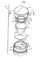
図面を参照して本発明を詳しく説明するに、図1には、例えば、フォグランンプであり得るLEDランプ10が示され、記号“F”で示す前方を向いた開口を提供するキャビティ16にして、後壁18を有するキャビティを画定する内壁14を持つハウジング12を含んでいる。ハウジング12は、例えばアルミニュームのような好適な金属から作製することが好ましく、キャビティの後壁18の外側22を伸延するヒートシンク20を含んでいる。
Referring to the drawings, the present invention will be described in detail. In FIG. 1, an
LED光源26が後壁18の、好ましくはボス18a(図2及び3に最も良く示される)の上方に固定され、前方“F”に、また前方“F”から90°までの範囲の側方“SW”に光を照射する。図1及び図2には、明瞭化の目的上3つのLED光源を示すが、好ましい実施例では、システム上の光学効率が約70%である5個のLED光源を用い得る。この光源の場合、ビームパターンはビーム拡がりが大きい、例えば、左右幅が35°以上あって中心ピーク強度が大きい(約3000カンデラ)のが理想的である。このビームパターンは、360ルーメン又はそれ以上のルーメン及び約15ワットを提供する5個のチップ光源により達成される。接合点温度は最大でも150℃以下とすべきである。
回路基板24をキャビティ16内で後壁18に隣り合わせて且つ後壁と熱的に連通する状態で取り付ける。回路基板は、LED光源26を受けるための切り欠き部24aを含む。
An
The
リフレクタ28はパラボラ状の反射性表面30を含み、反射性表面30は前方開口32と後方開口34とを有する。LED光源26を反射性表面30に向けた状態で後方開口34内に位置決めした状態でリフレクタ28をキャビティ16内に位置決めする。リフレクタ28はLED光源26からの光を遮断し、遮断した光を配向する。
光を十分に集めるためには中実のコリメート用レンズをLED光源26に十分接近させる必要がある。自動車での150℃の温度条件にも耐え得る透明材料はガラスだけであるが、ガラスは達成不能な光学上の幾つかの設計限界を有し、しかも高価である。
The
In order to collect light sufficiently, it is necessary to make a solid collimating lens sufficiently close to the
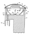
こうした欠点を無くすプラスチック製の複合プロジェクタレンズ38(以下、レンズ38)が提供される。レンズ38はハウジング12に連結されて回路基板24と、LED光源26と、リフレクタ28とを包囲し、プラスチック材料を使用可能とするべくLED光源26からは十分に離間され、また、複数の溝状レンズ40aを周囲縁部42に沿って配置した第1の光学反射性要素40と、レンズ中央に位置付けた凹凸状レンズ44aの形態の第2の光学反射性要素44とを有し、この凹凸状レンズ44a部分でLED光源26が直接結像される。つまり、凹凸状レンズは光を垂直方向に合焦させて高光度化し、水平方向には拡幅させる。標準的な投射レンズでビーム拡がりを大きくしようとすると光源からレンズまでの距離を数ミリメートルとする必要があるが、そうすると熱の問題が生じるのでレンズのこのレンズ部分を凹凸状形態とする必要がある。焦点距離が長く且つ直径が望ましく小さいことから、光の半分まではレンズを通過しないため、この不通過光を回収するためのリフレクタを設ける。リフレクタは不通過光を捕捉及びコリメート、即ち平行化して、レンズの溝状レンズ40aを含む外側又は周囲部分を通過させる。
A plastic composite projector lens 38 (hereinafter referred to as a lens 38) that eliminates these disadvantages is provided. The
随意的な保護カバー46をレンズ38を跨いで配置し、例えば、この保護カバー46から突出してハウジング12の雄部分62に係合する雌コネクタ60を使用してハウジング12に固定する。
ガスケット48を保護カバー46とハウジング12との間に位置決めし、キャビティ16にシール状態で取付ける。
ハウジング12の外側22には、自動車の電源電力を回路基板24に接続し、次いでLED光源に接続する給電線を受けるプラグカップリング50を形成する。
An optional
The
Formed on the
動作時は、レンズ38の周囲縁部42に沿って配置した第1の光学反射性要素40が、LED光源26から照射される光と、リフレクタ28から前方に配向される反射光とを遮る。第1の光学的反射要素40は遮った光を、水平方向の中心又は下方に位置付けた第1の水平方向バンド内に差し向ける。第2の光学反射性要素44はレンズ38上の中心に位置付けられ、LED光源26から前方に照射される直接光を遮断し、遮断した光を、第1の水平方向バンドに重ねた第2の水平方向バンドに差し向ける。
In operation, the first optically
かくして、本発明によれば、光を投射用の中心部分と、リフレクタからのコリメート光を縦方向溝を介して拡げる外側部分とを備える複合レンズを介して良好な光バランスを達成する、小型で、内蔵型のフォグランプが提供される。レンズはガラス又はプラスチック材料から形成し得るが、プラスチック製とするのが好ましい。レンズ構成はその他用途、例えば、ヘッドライト用のロービーム又はハイビーム、バックランプとして使用し得、又は特定のビームパターンを形成するように光学的プレゼンテーションを変更することで一般的な照明用途に使用できる。
以上、本発明を実施例を参照して説明したが、本発明の内で種々の変更をなし得ることを理解されたい。
Thus, according to the present invention, a small size is achieved that achieves a good light balance via a compound lens comprising a central portion for projecting light and an outer portion that spreads collimated light from the reflector through a longitudinal groove. A built-in fog lamp is provided. The lens may be formed from glass or plastic material, but is preferably made of plastic. The lens configuration can be used as a low light or high beam for headlights, as a backlamp, or for general lighting applications by modifying the optical presentation to form a specific beam pattern.
Although the present invention has been described with reference to the embodiments, it should be understood that various modifications can be made within the present invention.
10 LEDランプ
12 ハウジング
14 内壁
16 キャビティ
18a ボス
18 後壁
20 ヒートシンク
22 外側
24a 切り欠き部
24 回路基板
26 LED光源
28 リフレクタ
30 反射面
32 前方開口
34 後方開口
38 複合プロジェクタレンズ
40a 溝状レンズ
40 第1の光学反射性要素
42 周囲縁部
44a 凹凸状レンズ
44 第2の光学反射性要素
46 保護カバー
50 プラグカップリング
60 雌コネクタ
62 雄部分
DESCRIPTION OF
Claims (6)
前方を向いた開口を提供し且つ後壁を有するキャビティを画定する内壁を備え、キャビティの後壁の外側に伸延するヒートシンクを含むハウジングと、
キャビティの後壁に隣り合ってキャビティ内に取り付けられ、キャビティの後壁と熱的に連通する回路基板と、
回路基板で囲む状態でキャビティの後壁に取付けたLED光源にして、前方と、前方方向から90°までの範囲の側方とに光を照射するLED光源と、
前方開口と後方開口とを有するパラボラ状の反射面を含み、キャビティ内に位置決めしたリフレクタにして、前記LED光源がリフレクタの反射面を向くようにして後方開口内に位置決めされ、LED光源からの光を遮断し、遮断した光を配向するリフレクタと、
前記回路基板と、LED光源と、リフレクタとを包囲する状態でハウジングに連結したレンズにして、周囲縁部に沿って配置した第1の光学反射性要素と、カバーレンズ上の中心に位置付けた第2の光学反射性要素とを有するレンズと、
ハウジングの外側に形成したプラグカップリングにして、回路基板に電力を繋ぐための給電線を受けるプラグカップリングと、
を含むLEDランプ。 An LED lamp,
A housing including an inner wall defining a cavity having an opening facing forward and having a rear wall and extending outside the rear wall of the cavity;
A circuit board mounted in the cavity next to the back wall of the cavity and in thermal communication with the back wall of the cavity;
LED light source attached to the rear wall of the cavity in a state surrounded by a circuit board, and an LED light source that irradiates light to the front and the side in the range from the front direction to 90 °,
A reflector including a parabolic reflecting surface having a front opening and a rear opening, and a reflector positioned in the cavity, is positioned in the rear opening so that the LED light source faces the reflecting surface of the reflector. And a reflector for directing the blocked light,
A lens connected to the housing surrounding the circuit board, the LED light source, and the reflector, a first optical reflective element disposed along the peripheral edge, and a first lens positioned at the center on the cover lens A lens having two optically reflective elements;
A plug coupling formed on the outside of the housing, receiving a power supply line for connecting power to the circuit board, and
LED lamp including
前方“F”を向いた開口を提供し且つ後壁を有するキャビティを画定する内壁を備え、キャビティの後壁の外側に伸延するヒートシンクを含み、該ヒートシンクが半径方向に伸延して空気に露呈される少なくとも1つの薄い壁を含むハウジングと、
キャビティの後壁に隣り合ってキャビティ内に取り付けられ、キャビティの後壁と熱的に連通する回路基板と、
回路基板で囲む状態でキャビティの後壁に支持させたLED光源にして、前方“F”及び側方“SW”に光を照射するLED光源と、
反射面を含み、前方開口と後方開口とを有し、キャビティ内に位置決めしたリフレクタにして、回路基板を後壁に押し付けて回路基板から後壁への伝熱を良好化し、前記LED光源がリフレクタの反射面を向くようにして後方開口内に位置決めされ、リフレクタがLED光源からの光を遮断し、遮断した光を前方に配向するリフレクタと、
前記回路基板と、LED光源と、リフレクタとを包囲する状態でハウジングに連結したレンズにして、周囲縁部に沿って配置した第1の光学反射性要素と、レンズの中心に位置付けた第2の光学反射性要素とを有するレンズと、
を含み、
前記第1の光学反射性要素が複数の溝状レンズを含み、前記第2の光学的反射性要素が凹凸状レンズを含み、
ハウジングを跨ぎ且つキャビティをシールする状態で配置した保護カバーと、
ハウジングの外側に形成したプラグカップリングにして、回路基板に送電する給電線を受けるプラグカップリングと、
を含むLEDフォグランプ。 LED fog lamp,
A heat sink is provided that includes an inner wall defining an opening facing forward "F" and defining a cavity having a rear wall, the heat sink extending outwardly of the rear wall of the cavity, the heat sink extending radially and exposed to air. A housing including at least one thin wall;
A circuit board mounted in the cavity next to the back wall of the cavity and in thermal communication with the back wall of the cavity;
An LED light source that is supported on the rear wall of the cavity in a state surrounded by a circuit board, and that irradiates light to the front “F” and the side “SW”;
A reflector including a reflective surface, having a front opening and a rear opening, and positioned in the cavity, the circuit board is pressed against the rear wall to improve heat transfer from the circuit board to the rear wall, and the LED light source is a reflector. A reflector that is positioned in the rear opening so as to face the reflective surface of the light source, the reflector blocks light from the LED light source, and directs the blocked light forward;
A first optically reflective element disposed along a peripheral edge in a lens connected to the housing surrounding the circuit board, the LED light source, and the reflector, and a second positioned at the center of the lens A lens having an optically reflective element;
Including
The first optically reflective element includes a plurality of grooved lenses, the second optically reflective element includes an uneven lens;
A protective cover arranged across the housing and sealing the cavity;
Plug coupling formed on the outside of the housing, receiving a power supply line for transmitting power to the circuit board, and
LED fog lamp including
Applications Claiming Priority (2)
| Application Number | Priority Date | Filing Date | Title |
|---|---|---|---|
| US93784507P | 2007-06-30 | 2007-06-30 | |
| US12/011,866 US7686486B2 (en) | 2007-06-30 | 2008-01-30 | LED lamp module |
Publications (1)
| Publication Number | Publication Date |
|---|---|
| JP2009016347A true JP2009016347A (en) | 2009-01-22 |
Family
ID=39731451
Family Applications (1)
| Application Number | Title | Priority Date | Filing Date |
|---|---|---|---|
| JP2008170599A Pending JP2009016347A (en) | 2007-06-30 | 2008-06-30 | Led lamp module |
Country Status (4)
| Country | Link |
|---|---|
| US (1) | US7686486B2 (en) |
| EP (1) | EP2009345B1 (en) |
| JP (1) | JP2009016347A (en) |
| KR (1) | KR101510468B1 (en) |
Cited By (12)
| Publication number | Priority date | Publication date | Assignee | Title |
|---|---|---|---|---|
| CN101975368A (en) * | 2010-10-29 | 2011-02-16 | 铜陵科乐福新光电有限公司 | LED (Light Emitting Diode) grille lamp |
| CN101975362A (en) * | 2010-10-29 | 2011-02-16 | 铜陵科乐福新光电有限公司 | LED spotlight with heat radiating shield |
| CN101975366A (en) * | 2010-10-29 | 2011-02-16 | 铜陵科乐福新光电有限公司 | Combined light emitting diode (LED) down lamp |
| CN101975367A (en) * | 2010-10-29 | 2011-02-16 | 铜陵科乐福新光电有限公司 | Combined light-emitting diode (LED) grille lamp |
| CN102062340A (en) * | 2010-10-29 | 2011-05-18 | 铜陵科乐福新光电有限公司 | LED (light-emitting diode) down lamp with wiring terminal |
| JP2011198658A (en) * | 2010-03-19 | 2011-10-06 | Stanley Electric Co Ltd | Vehicular head light |
| JP2012109145A (en) * | 2010-11-18 | 2012-06-07 | Koito Mfg Co Ltd | Lamp unit |
| JP2012230834A (en) * | 2011-04-26 | 2012-11-22 | Koito Mfg Co Ltd | Vehicle lamp |
| JP2013502685A (en) * | 2009-08-19 | 2013-01-24 | コーニンクレッカ フィリップス エレクトロニクス エヌ ヴィ | Illumination device and lens suitable for such illumination device |
| KR101344210B1 (en) | 2012-07-11 | 2013-12-24 | 에스엔제이 주식회사 | Compact led lamp |
| JP2015053270A (en) * | 2009-05-25 | 2015-03-19 | エルジー イノテック カンパニー リミテッド | Gap member, lens, and luminaire having the same |
| US10253939B2 (en) | 2014-04-08 | 2019-04-09 | Ichikoh Industries, Ltd. | Lighting device for vehicle |
Families Citing this family (91)
| Publication number | Priority date | Publication date | Assignee | Title |
|---|---|---|---|---|
| KR100782798B1 (en) * | 2006-02-22 | 2007-12-05 | 삼성전기주식회사 | COB Package and Its Manufacturing method |
| US7881605B2 (en) * | 2007-03-02 | 2011-02-01 | Nikon Corporation | Camera with built-in projector and projector device |
| WO2009117834A1 (en) * | 2008-03-26 | 2009-10-01 | Magna International Inc. | Fog lamp and the like employing semiconductor light sources |
| US7637630B2 (en) * | 2008-04-22 | 2009-12-29 | Ruud Lighting, Inc. | Integrated shield-gasket member in LED apparatus |
| JP2009266434A (en) * | 2008-04-22 | 2009-11-12 | Koito Mfg Co Ltd | Light source module and lighting fixture for vehicle |
| CA2664963A1 (en) * | 2008-05-01 | 2009-11-01 | Magna International Inc. | Hotspot cutoff d-optic |
| US8382329B2 (en) * | 2008-05-15 | 2013-02-26 | Innovx Group Llc | Adjustable beam lamp |
| JP4576490B2 (en) | 2008-12-09 | 2010-11-10 | フェニックス電機株式会社 | Reflector for light emitting device and light emitting device using the same |
| CN102282412B (en) * | 2009-01-20 | 2014-05-14 | 松下电器产业株式会社 | Illuminating apparatus |
| US8246212B2 (en) * | 2009-01-30 | 2012-08-21 | Koninklijke Philips Electronics N.V. | LED optical assembly |
| US8220970B1 (en) * | 2009-02-11 | 2012-07-17 | Koninklijke Philips Electronics N.V. | Heat dissipation assembly for an LED downlight |
| US20100246203A1 (en) * | 2009-03-27 | 2010-09-30 | North American Lighting, Inc. | System and method for exterior lighting of vehicles |
| US8894260B2 (en) | 2009-03-31 | 2014-11-25 | Sicpa Holding Sa | Annular light guide illuminator and optical scanner |
| CN102667326B (en) | 2009-06-03 | 2016-08-10 | 沃克斯材料有限公司 | Lamp assembly and manufacture method |
| US20110032720A1 (en) * | 2009-08-04 | 2011-02-10 | Xiaolu Chen | High and low beam headlamp with a pivoting multifaceted reflector |
| NL2003489C2 (en) * | 2009-09-14 | 2011-03-15 | Wen-Sung Hu | Illumination-improving structure for led or smd led lights. |
| US20120218773A1 (en) * | 2009-09-25 | 2012-08-30 | Osram Opto Semiconductors Gmbh | Semiconductor luminaire |
| JP5481764B2 (en) * | 2009-10-08 | 2014-04-23 | スタンレー電気株式会社 | Vehicle lighting |
| EP2863117B1 (en) | 2009-11-09 | 2016-07-13 | LG Innotek Co., Ltd. | Lighting device |
| CN102869921B (en) | 2009-12-02 | 2015-07-22 | 沃克斯材料有限公司 | Structural headlamp assemblies for vehicular applications |
| KR200460816Y1 (en) * | 2010-02-05 | 2012-06-13 | 케이디지전자 주식회사 | FOG-LAMP for CAR |
| KR101506070B1 (en) * | 2010-04-05 | 2015-03-25 | 쿠퍼 테크놀로지스 컴파니 | Lighting assemblies having controlled directional heat transfer |
| KR101047439B1 (en) * | 2010-04-09 | 2011-07-08 | 엘지이노텍 주식회사 | Lens and lighting unit comprising lens |
| CA2740825C (en) | 2010-05-23 | 2014-03-18 | Rab Lighting, Inc. | Led housing with heat transfer sink |
| KR101285889B1 (en) * | 2010-06-23 | 2013-07-11 | 엘지전자 주식회사 | LED Lighting Device |
| KR101216084B1 (en) | 2010-06-23 | 2012-12-26 | 엘지전자 주식회사 | Lighting device and module type lighting device |
| KR101053633B1 (en) | 2010-06-23 | 2011-08-03 | 엘지전자 주식회사 | Module type lighting device |
| KR101057064B1 (en) * | 2010-06-30 | 2011-08-16 | 엘지전자 주식회사 | Led based lamp and method for manufacturing the same |
| US20130105670A1 (en) | 2010-07-02 | 2013-05-02 | Marko Borosak | Pulsed laser signal disrupting device incorporating led illuminator |
| KR101053634B1 (en) | 2010-07-02 | 2011-08-03 | 엘지전자 주식회사 | Led based lamp and method for manufacturing the same |
| WO2012005684A1 (en) * | 2010-07-05 | 2012-01-12 | I3 Lab Pte Ltd | Transmissive optical member in automotive led headlamp |
| US8651705B2 (en) * | 2010-09-07 | 2014-02-18 | Cree, Inc. | LED lighting fixture |
| US8628221B2 (en) | 2011-01-29 | 2014-01-14 | Chi Lin Technology Co., Ltd | Lamp |
| US9146027B2 (en) * | 2011-04-08 | 2015-09-29 | Ideal Industries, Inc. | Device for holding a source of LED light |
| WO2012151522A1 (en) * | 2011-05-04 | 2012-11-08 | Pickholz Michael F | Led lamp assembly |
| US9605843B2 (en) | 2011-07-11 | 2017-03-28 | Golight, Inc. | LED system and housing for use with halogen light |
| KR101911762B1 (en) * | 2011-08-09 | 2018-10-26 | 엘지이노텍 주식회사 | Lighting device |
| USD665437S1 (en) * | 2011-08-29 | 2012-08-14 | Johnson Jr Richard L | Secondary lens for a concentrating photovoltaic system module |
| US8449159B2 (en) | 2011-10-18 | 2013-05-28 | Lawrence M. Rice | Combination optics light emitting diode landing light |
| US8888320B2 (en) | 2012-01-27 | 2014-11-18 | Hubbell Incorporated | Prismatic LED module for luminaire |
| US9194556B1 (en) | 2012-02-22 | 2015-11-24 | Theodore G. Nelson | Method of producing LED lighting apparatus and apparatus produced thereby |
| CN102628577B (en) * | 2012-03-29 | 2015-12-09 | 陈志明 | A kind of high efficiency automotive LED Fog-proof light |
| CN102691959B (en) * | 2012-06-21 | 2016-05-25 | 刘德润 | Headlamp LED light source |
| US8714793B2 (en) | 2012-07-10 | 2014-05-06 | Osram Sylvania Inc. | LED headlight with one or more stepped upward-facing reflectors |
| US9068723B2 (en) * | 2012-07-21 | 2015-06-30 | Dean Andrew Wilkinson | Configurable lamp assembly |
| US8733992B2 (en) | 2012-10-01 | 2014-05-27 | Osram Sylvania, Inc. | LED low profile linear front fog module |
| US9249966B1 (en) | 2012-11-09 | 2016-02-02 | OptoElectronix, Inc. | High efficiency SSL thermal designs for traditional lighting housings |
| US9644830B2 (en) | 2013-02-04 | 2017-05-09 | Sunlite Science & Technology, Inc. | Application-specific LED module and associated LED point source luminaires |
| US9964266B2 (en) | 2013-07-05 | 2018-05-08 | DMF, Inc. | Unified driver and light source assembly for recessed lighting |
| US11255497B2 (en) | 2013-07-05 | 2022-02-22 | DMF, Inc. | Adjustable electrical apparatus with hangar bars for installation in a building |
| US10139059B2 (en) | 2014-02-18 | 2018-11-27 | DMF, Inc. | Adjustable compact recessed lighting assembly with hangar bars |
| US11060705B1 (en) | 2013-07-05 | 2021-07-13 | DMF, Inc. | Compact lighting apparatus with AC to DC converter and integrated electrical connector |
| US10551044B2 (en) | 2015-11-16 | 2020-02-04 | DMF, Inc. | Recessed lighting assembly |
| US10563850B2 (en) | 2015-04-22 | 2020-02-18 | DMF, Inc. | Outer casing for a recessed lighting fixture |
| US10753558B2 (en) | 2013-07-05 | 2020-08-25 | DMF, Inc. | Lighting apparatus and methods |
| US11435064B1 (en) | 2013-07-05 | 2022-09-06 | DMF, Inc. | Integrated lighting module |
| CN104421807A (en) * | 2013-08-22 | 2015-03-18 | 江苏卡威汽车工业集团有限公司 | Automotive light-emitting diode (LED) headlamp |
| TWM498990U (en) * | 2014-10-21 | 2015-04-11 | Lustrous Technology Ltd | AC LED module with surge protection function |
| CA3102022C (en) | 2015-05-29 | 2023-04-25 | DMF, Inc. | Lighting module for recessed lighting systems |
| USD851046S1 (en) | 2015-10-05 | 2019-06-11 | DMF, Inc. | Electrical Junction Box |
| US10209005B2 (en) | 2015-10-05 | 2019-02-19 | Sunlite Science & Technology, Inc. | UV LED systems and methods |
| FR3056687B1 (en) * | 2016-09-26 | 2021-01-22 | Luxor Lighting | LIGHTING DEVICE |
| CN108224164A (en) * | 2017-01-05 | 2018-06-29 | 乐雷光电技术(上海)有限公司 | A kind of ultra-narrow beam angle LED fountain lamps |
| CN108458291A (en) * | 2017-02-21 | 2018-08-28 | 漳州立达信光电子科技有限公司 | Floodlight tube module and preparation method thereof and floodlight tube combination |
| TR201703364A2 (en) * | 2017-03-06 | 2018-09-21 | Serdar Plastik Sanayi Ve Ticaret Anonim Sirketi | WORKING LAMP WITH SEALING LED |
| WO2018237294A2 (en) | 2017-06-22 | 2018-12-27 | DMF, Inc. | Thin profile surface mount lighting apparatus |
| US10488000B2 (en) | 2017-06-22 | 2019-11-26 | DMF, Inc. | Thin profile surface mount lighting apparatus |
| USD905327S1 (en) | 2018-05-17 | 2020-12-15 | DMF, Inc. | Light fixture |
| CN206846480U (en) * | 2017-07-06 | 2018-01-05 | 奚俊 | Dynamic Announce projection lamp |
| US11067231B2 (en) | 2017-08-28 | 2021-07-20 | DMF, Inc. | Alternate junction box and arrangement for lighting apparatus |
| CN111670322B (en) | 2017-11-28 | 2022-04-26 | Dmf股份有限公司 | Adjustable hanger rod assembly |
| WO2019133669A1 (en) | 2017-12-27 | 2019-07-04 | DMF, Inc. | Methods and apparatus for adjusting a luminaire |
| USD877957S1 (en) | 2018-05-24 | 2020-03-10 | DMF Inc. | Light fixture |
| CA3103255A1 (en) | 2018-06-11 | 2019-12-19 | DMF, Inc. | A polymer housing for a recessed lighting system and methods for using same |
| USD903605S1 (en) | 2018-06-12 | 2020-12-01 | DMF, Inc. | Plastic deep electrical junction box |
| CA3115146A1 (en) | 2018-10-02 | 2020-04-09 | Ver Lighting Llc | A bar hanger assembly with mating telescoping bars |
| USD864877S1 (en) | 2019-01-29 | 2019-10-29 | DMF, Inc. | Plastic deep electrical junction box with a lighting module mounting yoke |
| USD901398S1 (en) | 2019-01-29 | 2020-11-10 | DMF, Inc. | Plastic deep electrical junction box |
| USD1012864S1 (en) | 2019-01-29 | 2024-01-30 | DMF, Inc. | Portion of a plastic deep electrical junction box |
| KR101992117B1 (en) | 2019-01-31 | 2019-06-24 | (주)에이엠에스 | Fog light of vehicle equipped with halogen lamp capable of being replaced with led bulb as light source |
| KR102257476B1 (en) * | 2019-02-15 | 2021-05-31 | 한국광기술원 | Horizontal arrangement type multi division-multi lighting vehicle lighting device |
| USD966877S1 (en) | 2019-03-14 | 2022-10-18 | Ver Lighting Llc | Hanger bar for a hanger bar assembly |
| WO2021015058A1 (en) * | 2019-07-19 | 2021-01-28 | パナソニックIpマネジメント株式会社 | Lighting device |
| WO2021051101A1 (en) | 2019-09-12 | 2021-03-18 | DMF, Inc. | Miniature lighting module and lighting fixtures using same |
| CN110762402B (en) * | 2019-10-18 | 2021-03-30 | 华南半导体(广东)有限公司 | Manufacturing method of matrix type LED lamp source |
| USD990030S1 (en) | 2020-07-17 | 2023-06-20 | DMF, Inc. | Housing for a lighting system |
| CA3124976A1 (en) | 2020-07-17 | 2022-01-17 | DMF, Inc. | Polymer housing for a lighting system and methods for using same |
| US11585517B2 (en) | 2020-07-23 | 2023-02-21 | DMF, Inc. | Lighting module having field-replaceable optics, improved cooling, and tool-less mounting features |
| DE102020127952A1 (en) | 2020-10-23 | 2022-04-28 | HELLA GmbH & Co. KGaA | Lighting device for vehicles |
| TWI726829B (en) * | 2020-11-17 | 2021-05-01 | 坦德科技股份有限公司 | Light guide structure |
| EP4180711A1 (en) * | 2021-11-15 | 2023-05-17 | Robe Lighting s.r.o. | Homogenization of an led array |
Citations (3)
| Publication number | Priority date | Publication date | Assignee | Title |
|---|---|---|---|---|
| US1955599A (en) * | 1931-07-30 | 1934-04-17 | Us Holding Corp | Motor vehicle headlight |
| JPS62113301A (en) * | 1985-11-07 | 1987-05-25 | ロ−ベルト・ボツシユ・ゲゼルシヤフト・ミツト・ベシユレンクテル・ハフツング | Head lamp for dimmer or fog lighting of automobile |
| JP2005044699A (en) * | 2003-07-24 | 2005-02-17 | Koito Mfg Co Ltd | Lighting fixture for vehicle and light source module |
Family Cites Families (14)
| Publication number | Priority date | Publication date | Assignee | Title |
|---|---|---|---|---|
| US2556328A (en) * | 1944-11-16 | 1951-06-12 | Hinds Reinhard Paul Henry | Nonglare motor vehicle headlight |
| US3708221A (en) | 1970-04-02 | 1973-01-02 | Anchor Hocking Corp | Aspheric lens and method of manufacture |
| US3743385A (en) | 1970-04-02 | 1973-07-03 | Anchor Hocking Corp | Fresnel aspheric lens |
| US4207607A (en) * | 1977-06-17 | 1980-06-10 | Koehler Manufacturing Company | Luminaire apparatus for reflecting radiant energy and methods of controlling characteristics of reflected radiant energy |
| US5821695A (en) * | 1996-08-06 | 1998-10-13 | Appleton Electric Company | Encapsulated explosion-proof pilot light |
| EP1136749A4 (en) | 1999-09-30 | 2004-03-17 | Matsushita Electric Works Ltd | Illumination device |
| US6435691B1 (en) * | 1999-11-29 | 2002-08-20 | Watkins Manufacturing Corporation | Lighting apparatus for portable spas and the like |
| US6866401B2 (en) * | 2001-12-21 | 2005-03-15 | General Electric Company | Zoomable spot module |
| US6685339B2 (en) * | 2002-02-14 | 2004-02-03 | Polaris Pool Systems, Inc. | Sparkle light bulb with controllable memory function |
| EP1673573A4 (en) | 2003-10-06 | 2016-01-13 | Illumination Man Solutions Inc | Improved light source using light emitting diodes and an improved method of collecting the energy radiating from them |
| US7111972B2 (en) * | 2004-06-23 | 2006-09-26 | Osram Sylvania Inc. | LED lamp with central optical light guide |
| US7255460B2 (en) | 2005-03-23 | 2007-08-14 | Nuriplan Co., Ltd. | LED illumination lamp |
| CA2578396C (en) * | 2006-02-13 | 2015-09-22 | Brasscorp Limited | Reflectors, reflector/led combinations, and lamps having the same |
| TWM304736U (en) | 2006-07-06 | 2007-01-11 | Augux Co Ltd | Illuminating source structure for heat dissipation type LED signal lamp |
-
2008
- 2008-01-30 US US12/011,866 patent/US7686486B2/en not_active Expired - Fee Related
- 2008-06-26 KR KR20080060831A patent/KR101510468B1/en not_active IP Right Cessation
- 2008-06-26 EP EP20080011563 patent/EP2009345B1/en not_active Not-in-force
- 2008-06-30 JP JP2008170599A patent/JP2009016347A/en active Pending
Patent Citations (3)
| Publication number | Priority date | Publication date | Assignee | Title |
|---|---|---|---|---|
| US1955599A (en) * | 1931-07-30 | 1934-04-17 | Us Holding Corp | Motor vehicle headlight |
| JPS62113301A (en) * | 1985-11-07 | 1987-05-25 | ロ−ベルト・ボツシユ・ゲゼルシヤフト・ミツト・ベシユレンクテル・ハフツング | Head lamp for dimmer or fog lighting of automobile |
| JP2005044699A (en) * | 2003-07-24 | 2005-02-17 | Koito Mfg Co Ltd | Lighting fixture for vehicle and light source module |
Cited By (13)
| Publication number | Priority date | Publication date | Assignee | Title |
|---|---|---|---|---|
| JP2015053270A (en) * | 2009-05-25 | 2015-03-19 | エルジー イノテック カンパニー リミテッド | Gap member, lens, and luminaire having the same |
| US9423101B2 (en) | 2009-08-19 | 2016-08-23 | Koninklijke Philips N.V. | Lighting device having a lens including a plurality of interconnected elongated light-guiding elements |
| JP2013502685A (en) * | 2009-08-19 | 2013-01-24 | コーニンクレッカ フィリップス エレクトロニクス エヌ ヴィ | Illumination device and lens suitable for such illumination device |
| JP2011198658A (en) * | 2010-03-19 | 2011-10-06 | Stanley Electric Co Ltd | Vehicular head light |
| CN101975362A (en) * | 2010-10-29 | 2011-02-16 | 铜陵科乐福新光电有限公司 | LED spotlight with heat radiating shield |
| CN101975366A (en) * | 2010-10-29 | 2011-02-16 | 铜陵科乐福新光电有限公司 | Combined light emitting diode (LED) down lamp |
| CN101975367A (en) * | 2010-10-29 | 2011-02-16 | 铜陵科乐福新光电有限公司 | Combined light-emitting diode (LED) grille lamp |
| CN102062340A (en) * | 2010-10-29 | 2011-05-18 | 铜陵科乐福新光电有限公司 | LED (light-emitting diode) down lamp with wiring terminal |
| CN101975368A (en) * | 2010-10-29 | 2011-02-16 | 铜陵科乐福新光电有限公司 | LED (Light Emitting Diode) grille lamp |
| JP2012109145A (en) * | 2010-11-18 | 2012-06-07 | Koito Mfg Co Ltd | Lamp unit |
| JP2012230834A (en) * | 2011-04-26 | 2012-11-22 | Koito Mfg Co Ltd | Vehicle lamp |
| KR101344210B1 (en) | 2012-07-11 | 2013-12-24 | 에스엔제이 주식회사 | Compact led lamp |
| US10253939B2 (en) | 2014-04-08 | 2019-04-09 | Ichikoh Industries, Ltd. | Lighting device for vehicle |
Also Published As
| Publication number | Publication date |
|---|---|
| EP2009345A2 (en) | 2008-12-31 |
| EP2009345A3 (en) | 2009-04-01 |
| US7686486B2 (en) | 2010-03-30 |
| KR101510468B1 (en) | 2015-04-08 |
| EP2009345B1 (en) | 2012-06-20 |
| KR20090004569A (en) | 2009-01-12 |
| US20090003009A1 (en) | 2009-01-01 |
Similar Documents
| Publication | Publication Date | Title |
|---|---|---|
| JP2009016347A (en) | Led lamp module | |
| CA2628882C (en) | Led lamp module | |
| KR101847932B1 (en) | Lighting device module | |
| TWI422055B (en) | Led headlamp system | |
| JP5968682B2 (en) | Floodlight device and vehicle headlamp | |
| KR101500759B1 (en) | Rear-loaded light emitting diode module for automotive rear combination lamps | |
| JP5323998B2 (en) | Luminaire with phosphor, excitation light source, optical system, and heat sink | |
| US20170016586A1 (en) | Light source module and vehicle lamp | |
| JP2006294610A (en) | Virtual point-like light source | |
| JP2011062517A (en) | Operating light | |
| CN105782846B (en) | LED vehicle lighting device, LED vehicle headlamp and light emitting method of LED vehicle lighting device | |
| TW201333382A (en) | Lighting device and light collecting body used in the same | |
| US20170267163A1 (en) | Vehicle decorative lighting device and vehicle lamp | |
| JP2012119229A (en) | Vehicular headlight | |
| US7665868B2 (en) | Vehicle lamp | |
| CN105318281B (en) | Laser optical system for a headlamp | |
| JP6487768B2 (en) | Laser optics for vehicle lamps | |
| CN113728195A (en) | Vehicle headlamp | |
| CN104515049A (en) | Railway vehicle headlamp | |
| KR20210115171A (en) | LED lamp for ceiling and LED lamp lens | |
| JP2009245833A (en) | Lighting fixture for vehicle | |
| JP2010161048A (en) | Projector type vehicular headlamp | |
| JP6235081B2 (en) | Floodlight device and vehicle headlamp | |
| JP2006092887A (en) | Lamp | |
| CN219828609U (en) | Lighting assembly |
Legal Events
| Date | Code | Title | Description |
|---|---|---|---|
| A711 | Notification of change in applicant |
Free format text: JAPANESE INTERMEDIATE CODE: A712 Effective date: 20110422 |
|
| A621 | Written request for application examination |
Free format text: JAPANESE INTERMEDIATE CODE: A621 Effective date: 20110525 |
|
| A977 | Report on retrieval |
Free format text: JAPANESE INTERMEDIATE CODE: A971007 Effective date: 20121221 |
|
| A131 | Notification of reasons for refusal |
Free format text: JAPANESE INTERMEDIATE CODE: A131 Effective date: 20130129 |
|
| A521 | Written amendment |
Free format text: JAPANESE INTERMEDIATE CODE: A523 Effective date: 20130403 |
|
| A131 | Notification of reasons for refusal |
Free format text: JAPANESE INTERMEDIATE CODE: A131 Effective date: 20131008 |
|
| A02 | Decision of refusal |
Free format text: JAPANESE INTERMEDIATE CODE: A02 Effective date: 20140304 |