JP2009016151A - Drain recovery apparatus of fuel cell power generating device - Google Patents
Drain recovery apparatus of fuel cell power generating device Download PDFInfo
- Publication number
- JP2009016151A JP2009016151A JP2007175852A JP2007175852A JP2009016151A JP 2009016151 A JP2009016151 A JP 2009016151A JP 2007175852 A JP2007175852 A JP 2007175852A JP 2007175852 A JP2007175852 A JP 2007175852A JP 2009016151 A JP2009016151 A JP 2009016151A
- Authority
- JP
- Japan
- Prior art keywords
- drain
- pot
- pressure
- fuel cell
- cylinder member
- Prior art date
- Legal status (The legal status is an assumption and is not a legal conclusion. Google has not performed a legal analysis and makes no representation as to the accuracy of the status listed.)
- Pending
Links
Images


Classifications
-
- Y—GENERAL TAGGING OF NEW TECHNOLOGICAL DEVELOPMENTS; GENERAL TAGGING OF CROSS-SECTIONAL TECHNOLOGIES SPANNING OVER SEVERAL SECTIONS OF THE IPC; TECHNICAL SUBJECTS COVERED BY FORMER USPC CROSS-REFERENCE ART COLLECTIONS [XRACs] AND DIGESTS
- Y02—TECHNOLOGIES OR APPLICATIONS FOR MITIGATION OR ADAPTATION AGAINST CLIMATE CHANGE
- Y02E—REDUCTION OF GREENHOUSE GAS [GHG] EMISSIONS, RELATED TO ENERGY GENERATION, TRANSMISSION OR DISTRIBUTION
- Y02E60/00—Enabling technologies; Technologies with a potential or indirect contribution to GHG emissions mitigation
- Y02E60/30—Hydrogen technology
- Y02E60/50—Fuel cells
Abstract
Description
本発明は、固体高分子型燃料電池を用いた燃料電池発電装置で発生するドレンを回収するための燃料電池発電装置のドレン回収装置に関するものである。 The present invention relates to a drain recovery device of a fuel cell power generator for recovering drain generated in a fuel cell power generator using a solid polymer fuel cell.
燃料電池は、燃料を用いた他の発電方法に比して熱効率が高く、又、環境汚染が少ないため、有効な発電装置として期待されている。特に、固体高分子型燃料電池(PEFC)は、100℃以下という低温で発電が行われ、出力密度が高いので、他の形式の燃料電池に比して小型化でき、しかも、電池構成材料の劣化が少ないこと、起動が容易であること、等の長所があることから、近年、小規模な業務用あるいは家庭用等の発電装置として使用されるようになってきている。 A fuel cell is expected to be an effective power generation device because it has higher thermal efficiency and less environmental pollution than other power generation methods using fuel. In particular, the polymer electrolyte fuel cell (PEFC) generates power at a low temperature of 100 ° C. or lower, and has a high output density. Therefore, the polymer electrolyte fuel cell (PEFC) can be reduced in size as compared with other types of fuel cells. In recent years, it has been used as a power generator for small-scale business use or home use because it has advantages such as little deterioration and easy start-up.
上記固体高分子型燃料電池を用いた発電装置(PEFC発電装置)の一般的な構成は、以下のようにしてある。すなわち、電解質としてフッ素系のイオン交換膜が用いられている固体高分子電解質膜の両面をカソード(空気極)とアノード(燃料極)の両ガス拡散電極で挟持させてなるセルを、セパレータを介し積層してスタックとし、且つ数セルに1つずつの冷却部を備えてなる構成として固体高分子型燃料電池を形成する。上記固体高分子型燃料電池におけるアノードの入口側には、改質器、シフトコンバータ、CO除去器(CO選択酸化反応器)を順に備えてなる燃料処理装置を、途中に加湿器を備えた改質ガス配管を介し接続して、燃料供給部より供給される都市ガス(天然ガス)やメタノール等の原料を、水蒸気と共に上記燃料処理装置へ供給して、該燃料処理装置の改質器にて水蒸気改質を行わせ、得られる改質ガス(燃料ガス)を、シフトコンバータに導いてシフト反応させ、更に、上記CO除去器にてCO除去処理するようにしてあり、しかる後、上記燃料処理装置より送出される改質ガスが、改質ガス配管上に設けてある加湿器にて加湿された後、上記固体高分子型燃料電池のアノードへ供給されるようにしてある。一方、上記カソードの入口側には、酸化ガス(空気)が、圧縮器(空気ブロワ)で圧縮された後、酸化ガス配管上の加湿器を経てから供給されるようにしてある。 A general configuration of a power generation device (PEFC power generation device) using the polymer electrolyte fuel cell is as follows. That is, a cell in which both surfaces of a solid polymer electrolyte membrane in which a fluorine-based ion exchange membrane is used as an electrolyte is sandwiched between both cathode (air electrode) and anode (fuel electrode) gas diffusion electrodes is interposed via a separator. A polymer electrolyte fuel cell is formed by stacking to form a stack and having one cooling unit for every several cells. On the anode inlet side in the polymer electrolyte fuel cell, a fuel processing device comprising a reformer, a shift converter, and a CO remover (CO selective oxidation reactor) in this order is provided. The raw material such as city gas (natural gas) or methanol supplied from the fuel supply unit is supplied to the fuel processing apparatus together with water vapor, and is connected to the fuel processing apparatus by a reformer of the fuel processing apparatus. Steam reforming is performed, and the resulting reformed gas (fuel gas) is guided to a shift converter to undergo a shift reaction, and further subjected to CO removal treatment by the CO remover, and then the fuel treatment. The reformed gas delivered from the apparatus is humidified by a humidifier provided on the reformed gas pipe, and then supplied to the anode of the polymer electrolyte fuel cell. On the other hand, oxidizing gas (air) is supplied to the inlet side of the cathode after being compressed by a compressor (air blower) and then through a humidifier on the oxidizing gas pipe.
かかる構成としてあることにより、上記固体高分子型燃料電池にて、アノード側に供給される改質ガス中の水素と、カソード側に供給される酸化ガス(空気)中の酸素とを電気化学反応(燃料電池反応)させて、この際発生する起電力を取り出すようにしてある。 With this configuration, in the polymer electrolyte fuel cell, an electrochemical reaction between hydrogen in the reformed gas supplied to the anode side and oxygen in the oxidizing gas (air) supplied to the cathode side (Fuel cell reaction) and the electromotive force generated at this time is taken out.
又、上記固体高分子型燃料電池による燃料電池反応の後、アノードの出口より排出されるアノードオフガスには未反応の水素が残存している。そのため、上記アノードの出口側に接続してあるアノードオフガス配管を、上記燃料処理装置における改質器の燃焼室側のバーナに接続して、上記固体高分子型燃料電池のアノードオフガスを、上記アノードオフガス配管を経て上記燃料処理装置のバーナへ導いて燃焼させ、これにより、燃料処理装置における改質器の改質室にて水蒸気改質を行わせるための熱源として利用するようにしてある。 Further, after the fuel cell reaction by the polymer electrolyte fuel cell, unreacted hydrogen remains in the anode off-gas discharged from the anode outlet. Therefore, the anode off-gas pipe connected to the outlet side of the anode is connected to the burner on the combustion chamber side of the reformer in the fuel processor, and the anode off-gas of the polymer electrolyte fuel cell is connected to the anode. The fuel gas is introduced into the burner of the fuel processor via an off-gas pipe and burned, thereby being used as a heat source for performing steam reforming in the reforming chamber of the reformer in the fuel processor.
カソードの出口より排出されるカソードオフガスは、カソードオフガス配管を通して排出するようにしてある。 The cathode offgas discharged from the cathode outlet is discharged through the cathode offgas piping.
上記固体高分子型燃料電池発電装置は、上記したように固体高分子型燃料電池の運転温度が100℃以下であることから、固体高分子型燃料電池発電装置の系内では、燃料改質装置を除くと、上記改質ガス配管、酸化ガス配管、アノードオフガス配管、カソードオフガス配管には、ほぼ100℃以下でそれぞれ対応するプロセスガスが流れる構成となっている。 In the polymer electrolyte fuel cell power generator, since the operating temperature of the polymer electrolyte fuel cell is 100 ° C. or less as described above, the fuel reformer is used in the system of the polymer electrolyte fuel cell generator. Except for the above, the process gas corresponding to each of the reformed gas pipe, the oxidizing gas pipe, the anode offgas pipe, and the cathode offgas pipe flows at about 100 ° C. or less.
これに対し、上記したように、アノードへ供給する改質ガスは、燃料を水蒸気改質したものであることから水蒸気を多く含んでおり、更に、上記改質ガス及びカソードへ供給する酸化ガスは、それぞれ加湿器で加湿するようにしてあるため湿分を多く含んでいる。そのために、上記改質ガスや酸化ガスではドレンが発生し易い。又、これらのプロセスガスが燃料電池反応に供された後のアノードオフガスやカソードオフガスも湿分を多く含んでいて、ドレンが発生し易くなっている。 On the other hand, as described above, the reformed gas supplied to the anode contains a large amount of water vapor because it is obtained by steam reforming the fuel, and the reformed gas and the oxidizing gas supplied to the cathode are Since each humidifier is humidified, it contains a lot of moisture. For this reason, the reformed gas or oxidizing gas tends to generate drain. Further, the anode off-gas and cathode off-gas after these process gases are subjected to the fuel cell reaction also contain a lot of moisture, and drainage is likely to occur.
ところで、上記改質ガス及び酸化ガス中で発生したドレンが固体高分子型燃料電池のアノード及びカソードへ進入すると、電池電圧の低下をもたらす虞が懸念される。又、上記アノードオフガス中で発生したドレンが、上記改質器のバーナに吹き込まれるようになると、火炎が安定しなくなる等の不具合が生じる虞が懸念される。 By the way, when drain generated in the reformed gas and oxidizing gas enters the anode and cathode of the polymer electrolyte fuel cell, there is a concern that the battery voltage may be lowered. Moreover, when the drain generated in the anode off gas is blown into the burner of the reformer, there is a concern that there may be a problem that the flame becomes unstable.
上記のようなドレンに起因して固体高分子型燃料電池発電装置の安定性が損なわれる虞を未然に防止するための1つの手法としては、上記各種プロセスガスの配管を、ヒータによってドレンが発生しない温度間で加熱することが考えられる。しかし、この手法は、補機動力の増加に繋がってしまうという問題が生じる。 As one method for preventing the possibility of the stability of the polymer electrolyte fuel cell power generation device from being impaired due to the drain as described above, the drain is generated by the heater in the various process gas pipes. It is conceivable to heat between temperatures that do not. However, this method has a problem that it leads to an increase in auxiliary power.
そのために、上記ドレンによって固体高分子型燃料電池発電装置の安定性が損なわれる虞を未然に防止するための別の手法としては、上記改質ガスや酸化ガスやアノードオフガスの流路に、適宜ドレンポットやドレンの分離管を設けることで、上記改質ガスや酸化ガスで発生するドレンが上記固体高分子型燃料電池へ供給される虞を未然に防止するようにしたり、上記アノードオフガスにて発生するドレンが改質器のバーナへ吹き込まれる虞を未然に防止させるようにすることが考えられてきている(たとえば、特許文献1、特許文献2、特許文献3、特許文献4参照)。
Therefore, as another method for preventing the possibility that the stability of the polymer electrolyte fuel cell power generation device is impaired by the drain, the flow path of the reformed gas, oxidizing gas, or anode off gas is appropriately set. By providing a drain pot or a drain separation pipe, the drain generated by the reformed gas or oxidizing gas can be prevented from being supplied to the polymer electrolyte fuel cell, or the anode off gas can be used. It has been considered to prevent the generated drain from being blown into the reformer burner (see, for example,
なお、本発明者は、上記カソードオフガス中で発生するドレンを回収して、上記加湿器における加湿用の水として再利用することを考えている。又、燃料改質装置で生成させる水素リッチな改質ガスを、固体高分子型燃料電池の許容温度以下まで冷却するための構成として、上記改質ガスを水と直接接触させて冷却(ダイレクトクエンチ)するようにしてある水クエンチャを使用することを考えている。この場合には、該水クエンチャから、上記アノードガスの冷却に供した後の水が連続的に排出されるようになる。 In addition, this inventor is thinking about collect | recovering the drains which generate | occur | produce in the said cathode off gas, and reusing as the water for humidification in the said humidifier. In addition, as a configuration for cooling the hydrogen-rich reformed gas produced by the fuel reformer to below the allowable temperature of the polymer electrolyte fuel cell, the reformed gas is directly contacted with water and cooled (direct quench). ) Consider using a certain water quencher. In this case, the water after cooling the anode gas is continuously discharged from the water quencher.
ところが、上記したように、複数のドレン分離個所でドレンを分離するために、各ドレン分離個所ごとに個別のドレンポットを設ける場合は、該各ドレンポットごとに個別に液面管理を行わなければならず、又、機器数が増加してしまう。更に、制御的にも複雑になるというのが実状である。 However, as described above, in order to separate drains at a plurality of drain separation points, when a separate drain pot is provided for each drain separation point, the liquid level must be individually controlled for each drain pot. In addition, the number of devices increases. Furthermore, the actual situation is that the control is complicated.
そのため、ドレンを一個所に集中させて、1つのドレンポットへすべてのドレンを回収するようにすれば、ドレンの液面管理を1つのドレンポットで行うことができて、ドレンの液面管理をより容易なものとすることができると考えられる。 Therefore, if the drain is concentrated in one place and all the drain is collected in one drain pot, the drain level can be controlled by one drain pot, and the drain level can be controlled. It is thought that it can be made easier.
しかし、実際には、上記固体高分子型燃料電池発電装置にて、ドレンが発生する各種プロセスガスの流路は、流通するガスの圧力がそれぞれ異なっているため、上記各種プロセスガスの流路よりドレンを導くためのドレン回収ラインを、1つのドレンポットに単に接続しても、すべてのドレンを上記1つのドレンポットに集めることは困難である。すなわち、圧力の高いガスの流路からは、ドレンポットへドレン以外にガスも流入して、ガスのショートパスラインが形成されてしまう虞が生じる。一方、圧力の低いガスの流路に対しては、ドレンポット内のドレンが上記圧力の低いガスの流路へ逆流して、バブリングを生じると云う虞が生じる。 However, in actuality, in the polymer electrolyte fuel cell power generator, the flow paths of the various process gases from which the drain is generated are different from the flow paths of the various process gases. Even if the drain recovery line for guiding the drain is simply connected to one drain pot, it is difficult to collect all the drains in the one drain pot. That is, there is a possibility that gas other than the drain flows into the drain pot from the gas flow path having a high pressure, thereby forming a gas short pass line. On the other hand, with respect to the low pressure gas flow path, there is a possibility that the drain in the drain pot flows back to the low pressure gas flow path and causes bubbling.
したがって、現状では、流通するプロセスガスの圧力が近似している系統同士は、ドレン配管を集合させることが可能であるが、ガスの圧力の異なる系統については、それぞれ別々に、ドレンポットを備えたドレンの排出機構を設けるようにせざるを得ず、このために、該各ドレン排出機構ごとのドレンの液面管理が必要とされる。 Therefore, at present, drain pipes can be assembled between systems with similar pressures of circulating process gas. However, systems with different gas pressures are each provided with a drain pot. Therefore, it is necessary to provide a drain discharge mechanism. For this reason, it is necessary to manage the drain level for each drain discharge mechanism.
そこで、本発明は、固体高分子型燃料電池発電装置における複数のドレン分離個所で分離するドレンを、ガスの圧力が異なる系統であるとしても、1つの共通のドレンポットへ一緒に回収できるようにし、更には、燃料改質装置で生成させる水素リッチな改質ガスを水と直接接触させて冷却するようにしてある水クエンチャより排出される水をも一緒に回収でき、且つ液面管理をすべて一括して行うことができる燃料電池発電装置のドレン回収装置を提供しようとするものである。 Therefore, the present invention makes it possible to collect the drains separated at a plurality of drain separation points in the solid polymer fuel cell power generator together into one common drain pot even if the gas pressures are different systems. Furthermore, the hydrogen-rich reformed gas produced by the fuel reformer can be cooled by direct contact with water, and the water discharged from the water quencher can be recovered together, and all liquid level control can be performed. It is an object of the present invention to provide a drain recovery device for a fuel cell power generation device that can be performed collectively.
本発明は、上記課題を解決するために、請求項1に対応して、燃料電池発電装置における複数のドレン分離個所よりドレンを導くドレン配管を、共通のドレンポットに接続し、且つ上記ドレンポットよりも高い圧力を有するドレン分離個所のうち、最も圧力の高いドレン分離個所からドレンを導くドレン配管を水封できるように上記ドレンポットの液面レベルを定め、更に、上記ドレンポットより圧力の低いドレン分離個所は、上記ドレンポットの液面レベルよりも、それぞれのドレンポットとの圧力差に相当する水柱の高さ寸法以上の高所となる高さレベルに配設してなる構成とする。 In order to solve the above-mentioned problem, the present invention, corresponding to claim 1, connects drain pipes for leading drains from a plurality of drain separation points in the fuel cell power generator to a common drain pot, and the drain pot Among the drain separation points having a higher pressure, the liquid level of the drain pot is determined so that the drain pipe for leading the drain from the drain separation point having the highest pressure can be sealed with water, and the pressure is lower than that of the drain pot. The drain separation part is configured to be disposed at a height level that is higher than the height of the water column corresponding to the pressure difference from each drain pot rather than the liquid level of the drain pot.
又、上記構成において、ドレンポットよりも高い圧力を有するドレン分離個所と、ドレンポットとの間に、中間水封ヘッダを設けるようにした構成とする。 Moreover, in the said structure, it is set as the structure which provided the intermediate water seal header between the drain separation part which has a pressure higher than a drain pot, and a drain pot.
更に、上記構成における中間水封ヘッダを、上下方向に所要寸法延び且つ上下両端部が閉塞された外筒部材と、該外筒部材の上部所要高さ位置から、外筒部材の底板を貫通して該外筒部材の下方位置まで上下方向に延びる内筒部材と、該内筒部材の下端側をドレンポットに連通させると共に、上記外筒部材をドレンポットに一体に連結する連結部と、上記外筒部材の上方位置から、該外筒部材の天井板を貫通して該外筒部材の内底部付近まで上下方向に延びるドレン流入管を備えてなる構成として、上記ドレン流入管の上端部に、ドレン分離個所よりドレンを導くドレン配管を接続するようにした構成とする。 Further, the intermediate water-sealed header in the above configuration penetrates the bottom plate of the outer cylinder member from the outer cylinder member whose required dimension extends in the vertical direction and whose upper and lower ends are closed, and the upper required height position of the outer cylinder member. An inner cylinder member extending vertically to the lower position of the outer cylinder member, a lower end side of the inner cylinder member communicated with the drain pot, and a connecting portion for integrally connecting the outer cylinder member to the drain pot; As a configuration comprising a drain inflow pipe extending vertically from the upper position of the outer cylinder member to the vicinity of the inner bottom of the outer cylinder member through the ceiling plate of the outer cylinder member, the upper end of the drain inflow pipe is The drain pipe for leading the drain from the drain separation point is connected.
上述の各構成におけるドレンポットとして、ブロワにより加圧して燃料電池のカソードへ供給する酸化ガスを加湿するための加湿器を用いるようにした構成とする。 The drain pot in each of the above-described configurations is configured to use a humidifier for humidifying the oxidizing gas pressurized by the blower and supplied to the cathode of the fuel cell.
又、上述の各構成において、ドレンポットよりも高い圧力を有するドレン分離個所のうち、最も圧力の高いドレン分離個所を、改質ガスを冷却するための水クエンチャとした構成とする。 In each of the above-described configurations, the drain separation location having the highest pressure among the drain separation locations having a pressure higher than that of the drain pot is configured as a water quencher for cooling the reformed gas.
本発明の燃料電池発電装置のドレン回収装置によれば、以下の如き優れた効果を発揮する。
(1)燃料電池発電装置における複数のドレン分離個所よりドレンを導くドレン配管を、共通のドレンポットに接続し、且つ上記ドレンポットよりも高い圧力を有するドレン分離個所のうち、最も圧力の高いドレン分離個所からドレンを導くドレン配管を水封できるように上記ドレンポットの液面レベルを定め、更に、上記ドレンポットより圧力の低いドレン分離個所は、上記ドレンポットの液面レベルよりも、それぞれのドレンポットとの圧力差に相当する水柱の高さ寸法以上の高所となる高さレベルに配設してなる構成としてあるので、圧力が異なる複数のドレン分離個所より出るドレンを、1つの共通のドレンポットへパッシブに回収することができる。しかも、上記ドレンポットより高い圧力のドレン分離個所よりドレンポットへガスが吹き抜けてガスのショートパスラインが形成される虞、及び、上記ドレンポットよりも低い圧力のドレン分離個所に対してドレンが逆流する虞を、未然に且つ確実に防止することができる。
(2)したがって、燃料電池発電装置で生じるドレンの液面管理を、1つのドレンポットで実施することが可能になるため、該ドレンの液面管理を容易なものとすることができる。又、燃料電池発電装置におけるドレンの回収のために要する機器数の削減化を図ることができると共に、制御を簡単なものとすることが可能になる。
(3)ドレンポットよりも高い圧力を有するドレン分離個所と、ドレンポットとの間に、中間水封ヘッダを設けるようにした構成とすることにより、上記ドレンポットよりも高い圧力を有するドレン分離個所と、ドレンポットとの圧力差が大きい場合にも、ドレンポットの液面レベルを低く抑えることができて、ドレン回収装置の高さ寸法を低く抑えることが可能になる。
(4)中間水封ヘッダを、上下方向に所要寸法延び且つ上下両端部が閉塞された外筒部材と、該外筒部材の上部所要高さ位置から、外筒部材の底板を貫通して該外筒部材の下方位置まで上下方向に延びる内筒部材と、該内筒部材の下端側をドレンポットに連通させると共に、上記外筒部材をドレンポットに一体に連結する連結部と、上記外筒部材の上方位置から、該外筒部材の天井板を貫通して該外筒部材の内底部付近まで上下方向に延びるドレン流入管を備えてなる構成として、上記ドレン流入管の上端部に、ドレン分離個所よりドレンを導くドレン配管を接続するようにした構成とすることにより、上記中間水封ヘッダを上記ドレンポットと一体化することができて、ドレン回収装置のコンパクト化をはかるのに有利なものとすることができる。
(5)ドレンポットとして、ブロワにより加圧して燃料電池のカソードへ供給する酸化ガスを加湿するための加湿器を用いるようにした構成とすることにより、回収するドレンを上記酸化ガスを加湿するための水として直接利用することができる。又、上記酸化ガスを加湿するための水とは別に回収するドレンを貯めるためのタンクを設ける必要をなくすことができて、装置のコンパクト化を図るのに有利なものとすることができる。しかも、上記加湿器内は、ブロワにより加圧した酸化ガスが流通しているために所要の圧力が作用していることから、各ドレン分離個所との差圧を小さく抑えることができて、ドレンポットの液面レベルを低く抑えることが可能になる。
(6)ドレンポットよりも高い圧力を有するドレン分離個所のうち、最も圧力の高いドレン分離個所を、改質ガスを冷却するための水クエンチャとした構成とすることにより、燃料改質装置で改質してなる改質ガスを、燃料電池へ供給する改質ガス経路における上流部に存在して、改質ガスの圧力が高くなっている水クエンチャより排出されるドレンを効率よく回収することができる。
According to the drain recovery device of the fuel cell power generator of the present invention, the following excellent effects are exhibited.
(1) Drain having the highest pressure among the drain separation points where the drain pipes for leading the drains from the plurality of drain separation points in the fuel cell power generator are connected to a common drain pot and have a higher pressure than the drain pot. The liquid level of the drain pot is determined so that the drain pipe for leading the drain from the separation part can be sealed with water, and the drain separation part whose pressure is lower than that of the drain pot is more than the liquid level of the drain pot. Since it is configured to be arranged at a height level that is higher than the height of the water column corresponding to the pressure difference with the drain pot, drains from multiple drain separation points with different pressures are shared by one common Can be recovered passively into the drain pot. In addition, there is a risk that gas will blow into the drain pot from the drain separation point at a pressure higher than that of the drain pot, and a short pass line of gas may be formed, and the drain backflows to the drain separation point at a pressure lower than that of the drain pot. The risk of this can be prevented in advance and reliably.
(2) Therefore, since it becomes possible to carry out the liquid level management of the drain produced in the fuel cell power generation device with one drain pot, the liquid level management of the drain can be facilitated. In addition, it is possible to reduce the number of devices required for collecting the drain in the fuel cell power generation apparatus and to simplify the control.
(3) A drain separation part having a pressure higher than that of the drain pot by providing an intermediate water seal header between the drain separation part having a pressure higher than that of the drain pot and the drain pot. Even when the pressure difference with the drain pot is large, the liquid level of the drain pot can be kept low, and the height dimension of the drain recovery device can be kept low.
(4) An intermediate water seal header is inserted through the bottom plate of the outer cylinder member from the required height position of the outer cylinder member, the outer cylinder member extending in the vertical direction and having the required dimension extended and closed at both upper and lower ends. An inner cylinder member extending in the vertical direction to a position below the outer cylinder member; a connecting portion for connecting the lower end side of the inner cylinder member to the drain pot; and connecting the outer cylinder member to the drain pot integrally; and the outer cylinder A drain inflow pipe extending vertically from the upper position of the member to the vicinity of the inner bottom of the outer cylinder member through the ceiling plate of the outer cylinder member is provided at the upper end of the drain inflow pipe. By adopting a configuration in which a drain pipe that guides the drain from the separation point is connected, the intermediate water seal header can be integrated with the drain pot, which is advantageous for downsizing the drain recovery device. To be Kill.
(5) A humidifier for humidifying the oxidizing gas supplied to the cathode of the fuel cell by pressurizing with a blower is used as the drain pot, so that the recovered drain can be humidified with the oxidizing gas. Can be used directly as water. Further, it is possible to eliminate the need to provide a tank for storing the drain to be collected separately from the water for humidifying the oxidizing gas, which can be advantageous for making the apparatus compact. In addition, since the required pressure is applied because the oxidizing gas pressurized by the blower is circulating in the humidifier, the pressure difference with each drain separation point can be suppressed to a small value. The liquid level of the pot can be kept low.
(6) Among the drain separation points having a pressure higher than that of the drain pot, the drain separation point having the highest pressure is configured as a water quencher for cooling the reformed gas, so that the fuel reformer can be modified. It is possible to efficiently recover the drain discharged from the water quencher where the reformed gas is present in the upstream portion of the reformed gas path for supplying the fuel cell and the pressure of the reformed gas is high it can.
以下、本発明を実施するための最良の形態を図面を参照して説明する。 The best mode for carrying out the present invention will be described below with reference to the drawings.
図1は本発明の燃料電池発電装置のドレン回収装置の実施の一形態を示すもので、以下のようにしてある。 FIG. 1 shows an embodiment of a drain recovery device for a fuel cell power generator according to the present invention, which is as follows.
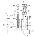
すなわち、図1に示した燃料電池発電装置のドレン回収装置は、固体高分子型燃料電池発電装置における固体高分子型燃料電池1のアノード2の入口側に接続してある改質ガス配管4を流通する改質ガス5より発生して上記アノード2の入口より出るドレン6と、ブロワ7より加湿器8を経てカソード3の入口側に接続してある酸化ガス配管9を流通する酸化ガス(空気)10より発生して上記カソード3の入口より出るドレン6と、アノードオフガスライン11上に設けたアノード出口気液分離器12にてアノードオフガス13より分離するドレン6と、カソードオフガスライン14上に設けたカソード出口気液分離器15にてカソードオフガス16より分離するドレン6と、上記改質ガス配管4上に設けて図示しない燃料改質装置で生成させる改質ガス5を水と直接接触させて冷却するための水クエンチャ17より上記改質ガス5の冷却に供された後に連続的に排出される水としてのドレン6とを、上記加湿器8の水タンクを1つの共通のドレンポット8aとして、一緒に回収することができるようにした構成とする。
That is, the drain recovery device of the fuel cell power generator shown in FIG. 1 has a reformed
以下、詳述する。 Details will be described below.
ここで、上記各ドレン分離個所における圧力について示すと、先ず、上記ドレンポット8aの圧力P0は、ブロワ7より供給される酸化ガス(空気)10を、加湿器8自体を経た後、酸化ガス配管9、固体高分子型燃料電池1のカソード3を順次流通させる際に生じる圧力損失に相当する圧力となっている。
Here, the pressure at each drain separation point will be described. First, the pressure P0 of the
次に、上記水クエンチャ17の圧力P1は、上記図示しない燃料改質装置で生成させた改質ガス5を、該水クエンチャ17自体を経た後、改質ガス配管4、固体高分子型燃料電池1のアノード2を順次流通させる際に生じる圧力損失に相当する圧力となっており、しかも、上記水クエンチャ17の圧力P1は、上記ドレンポット8aの圧力P0よりも高く(P1>P0)なっている。
Next, the pressure P1 of the
次いで、上記アノード2の入口側の圧力P2は、上記水クエンチャ17より改質ガス配管4を通して導かれる改質ガス5を、該アノード2に流通させる際に生じる圧力損失に相当する圧力となっており、上記水クエンチャ17の圧力P1よりも該水クエンチャ17自体の内部圧力損失に相当する分、圧力が低く(P2<P1)なっている。又、本実施の形態で示す固体高分子型燃料電池1の場合は、上記アノード2の入口側の圧力P2は、上記ドレンポット8aの圧力P0よりも高く(P2>P0)なるように設定してあるものとする。
Next, the pressure P2 on the inlet side of the
上記カソード3の入口側の圧力P3は、上記加湿器8より酸化ガス配管9を通して導かれる酸化ガス10を、該カソード3に流通させる際に生じる圧力損失に相当する圧力となっており、上記加湿器8の圧力、すなわち、ドレンポット8aの圧力P0よりも該加湿器8自体の内部圧力損失に相当する分、圧力が低く(P3<P0)なっている。
The pressure P3 on the inlet side of the
上記アノード出口気液分離器12の圧力P4は、上記アノード2の入口側の圧力P2よりも、該アノード2の内部圧力損失に相当する分、圧力が低下した値(P4<P2)となっている。
The pressure P4 of the anode outlet gas-
更に、上記カソード出口気液分離器15の圧力P5は、上記カソード3の入口側の圧力P3よりも、該カソード3の内部圧力損失に相当する分、圧力が低下した値(P5<P3)となっている。又、本実施の形態で示す固体高分子型燃料電池1の場合、該カソード出口気液分離器15の圧力P5は、上記アノード出口気液分離器12の圧力P4よりも低い圧力(P5<P4)となるようにしてある。
Further, the pressure P5 of the cathode outlet gas-
以上のように、それぞれ圧力の異なる系統に属する各ドレン分離個所からのドレン6を、上記共通のドレンポット8aへ回収できるようにするために、本発明の燃料電池発電装置のドレン回収装置では、第1に、上記各ドレン分離個所のうち、最も高い圧力を有するドレン分離個所である上記水クエンチャ17の圧力P1に着目して、該水クエンチャ17の圧力P1が、上記ドレンポット8aの圧力P0を上回る圧力差(P1−P0)に応じて、水クエンチャ17よりドレン6を導くドレン配管18を水封できるように、上記ドレンポット8aの液面レベルh0を設定する。
As described above, in order to be able to recover the
より具体的には、上記水クエンチャ17の圧力P1と、ドレンポット8aの圧力P0との圧力差1kPa当り100mm以上の割合で、上記ドレンポット8aにおける液面レベルh0が、該ドレンポット8aにおける上記ドレン配管18の接続個所の高さレベルよりも上方に位置するように、該ドレンポット8aの液面レベルh0を設定するようにした構成としてある。
More specifically, the liquid level h0 in the
すなわち、このドレンポット8aの液面レベルh0の設定により、上記ドレン配管18の接続個所に作用する圧力(単位面積当たりに作用する水柱の圧力、以下同様)を便宜的にh0で示すと、以下の式(1)が成り立つようにしてある。
That is, by setting the liquid level h0 of the
P0+h0>P1 ・・・(1)
更に、上記水クエンチャ17を設置する高さ位置は、上記ドレンポット8aの液面レベルh0よりも所要寸法上方となる高さ位置に配設するようにする。これにより、固体高分子型燃料電池発電装置の運転停止時に、上記水クエンチャ17の圧力がゼロの場合であっても、上記ドレンポット8a内に貯留されているドレン6が、上記水クエンチャ17へ逆流する虞はない。又、上記固体高分子型燃料電池発電装置の運転時に上記水クエンチャ17に圧力P1が作用するようになると、該水クエンチャ17の圧力P1と、上記ドレンポット8aの圧力P0との圧力差が生じるために、上記ドレン配管18内のドレン6が、上記圧力P1と圧力P0の圧力差(P1−P0)に応じてドレンポット8a側へ押し込まれて、該ドレン配管18内の液面レベルh1が、上記ドレンポットの液面レベルh0よりも低下するようになる。しかし、この場合であっても、上記式(1)のようにドレンポット8aの液面レベルh0が設定してあることにより、該ドレン配管18内の液面レベルh1が、上記ドレンポット8aに対するドレン配管18の接続個所の高さレベルを下回ることがないため、上記ドレン配管18の水封が確実に行われて、水クエンチャ17を流通している改質ガス5が、上記ドレンポット8aへ吹き抜ける虞を未然に防止できるようにしてある。
P0 + h0> P1 (1)
Furthermore, the height position where the
次に、上記したように、固体高分子型燃料電池1のアノード2の入口側の圧力P2は、上記ドレンポット8aの圧力P0よりも高い圧力となっている。一方、上記カソード3の入口側の圧力P3は、上記ドレンポット8aの圧力P0よりも低い圧力となっている。以上のことに鑑みて、上記アノード2の入口から出るドレン6と、上記カソード3の入口から出るドレン6の分離個所、すなわち、固体高分子型燃料電池1自体を配設する高さレベルh2が、上記ドレンポット8aの圧力P0とカソード3の入口側の圧力P3との圧力差1kPa当り100mm以上の割合で、上記ドレンポット8aの液面レベルh0よりも上方に位置するように、該固体高分子型燃料電池1の高さレベルh2を設定して配設するようにしてある。更に、上記アノード2及びカソード3の入口から出るドレン6を導くためのドレン配管19,20を、上記水クエンチャ17からのドレン6を導くドレン配管18の途中位置に合流させるようにそれぞれ接続した構成としてある。これにより、以下の式(2)が成り立つようになる。
Next, as described above, the pressure P2 on the inlet side of the
P3+h2>P0 ・・・(2)
したがって、固体高分子型燃料電池発電装置の運転時に、上記カソード3の入口側の圧力P3が、ドレンポット8aの圧力P0より低下すると、該カソード3の入口から出るドレン6をドレンポット8aへ導くドレン配管20内では、該ドレンポット8a内に貯留されているドレン6が、上記圧力P3と圧力P0の圧力差(P0−P3)に応じて上記カソード3側へ押し込まれて、該ドレン配管20内における液面レベルが上昇するようになる。しかし、この場合であっても、上記式(2)のように固体高分子型燃料電池1の高さレベルh2が設定してあることで、上記ドレンポット8a内のドレン6がカソード3の入口側におけるドレン分離個所まで上昇して逆流する虞を未然に防止できるようにしてある。又、上記固体高分子型燃料電池発電装置の運転時には、上記アノード2の入口側の圧力P2は、上記ドレンポット8aの圧力P0より高くなるが、上記アノード2の入口側の圧力P2は、上述した水クエンチャ17の圧力P1より低いため、アノード2の入口より出るドレン6を上記ドレンポット8aへ導くドレン配管19は、上記水クエンチャ7とドレンポット8aを接続しているドレン配管18と同様の原理で確実に水封することができる。このため、上記固体高分子型燃料電池1のアノード2へ供給される改質ガス5が、上記ドレンポット8aへ吹き抜ける虞を未然に防止できるようにしてある。
P3 + h2> P0 (2)
Accordingly, when the pressure P3 on the inlet side of the
次いで、上記アノード出口気液分離器12の圧力P4は、上記ドレンポット8aの圧力P0よりも低い圧力となっている。このことに鑑みて、上記アノード出口気液分離器12は、その配設する高さレベルh3が、上記ドレンポット8aの圧力P0とアノード出口気液分離器の圧力P4との圧力差1kPa当り100mm以上の割合で、上記ドレンポット8aの液面レベルh0よりも上方に位置するように、該アノード出口気液分離器12の高さレベルh3を設定して配設するようにしてある。更に、ドレン配管21を介してドレンポット8aに接続した構成としてある。これにより、以下の式(3)が成り立つようになる。
Next, the pressure P4 of the anode outlet gas-
P4+h3>P0 ・・・(3)
したがって、固体高分子型燃料電池発電装置の運転時に、上記アノード出口気液分離器12の圧力P4が、ドレンポット8aの圧力P0より低下することにより、該アノード出口気液分離器12のドレン6をドレンポット18aへ導くドレン配管21内では、ドレンポット8a内に貯留されているドレン6が、上記圧力P4と圧力P0の圧力差(P0−P4)に応じて上記アノード出口気液分離器12側へ押し込まれて、該ドレン配管21内における液面レベルが上昇するようになる。しかし、この場合であっても、上記式(3)のようにアノード出口気液分離器12の高さレベルh3が設定してあるため、上記ドレンポット8a内のドレン6がアノード出口気液分離器12まで上昇して逆流する虞を未然に防止できるようにしてある。
P4 + h3> P0 (3)
Accordingly, when the polymer electrolyte fuel cell power generator is operated, the pressure P4 of the anode outlet gas-
次いで、上記カソード出口気液分離器15の圧力P5は、上記ドレンポット8aの圧力P0よりも低い圧力となっている。このことに鑑みて、上記カソード出口気液分離器15は、その配設する高さレベルh4が、上記ドレンポット8aの圧力P0とアノード出口気液分離器15の圧力P5との圧力差1kPa当り100mm以上の割合で、上記ドレンポット8aの液面レベルh0よりも上方に位置するように、該アノード出口気液分離器15の高さレベルh4を設定して配設するようにしてある。更に、ドレン配管22を介して上記アノード出口気液分離器12よりドレンポット8aへドレン6を導くドレン配管21途中位置に合流させるように接続した構成としてある。これにより、以下の式(4)が成り立つようになる。
Next, the pressure P5 of the cathode outlet gas-
P5+h4>P0 ・・・(4)
したがって、固体高分子型燃料電池発電装置の運転時に、上記カソード出口気液分離器15の圧力P5が、ドレンポット8aの圧力P0より低下することにより、該カソード出口気液分離器15のドレン6をドレンポット8aへ導くドレン配管22内では、ドレンポット8a内に貯留されているドレン6が、上記圧力P5と圧力P0の圧力差(P0−P5)に応じて上記カソード出口気液分離器15側へ押し込まれて、該ドレン配管22内における液面レベルが上昇する。しかしこの場合であっても、上記式(4)のようにカソード出口気液分離器15の高さレベルh4が設定してあるため、上記ドレンポット8a内のドレン6がカソード出口気液分離器15まで上昇して逆流する虞を未然に防止できるようにしてある。
P5 + h4> P0 (4)
Accordingly, when the polymer electrolyte fuel cell power generator is operated, the pressure P5 of the cathode outlet gas-
なお、上記各プロセスガスの配管4,9,11,14には、図示したような勾配を適宜設けて、ドレン6を円滑に排出できるようにしてあるものとする。23はカソードオフガス16の排熱を回収するためのカソードオフガス熱回収器である。
The
以上の構成としてあるドレン回収装置を装備した固体高分子型燃料電池発電装置を運転すると、固体高分子型燃料電池1のアノード2へ供給される改質ガス5中の湿分が凝縮することによって生じるドレン6は、自重により上記アノード2の入口よりドレン配管19を経てドレンポット8aへ回収される。一方、カソード3へ供給される酸化ガス10中の湿分が凝縮することによって生じるドレン6は、自重により上記カソード3の入口よりドレン配管20を経て上記ドレンポット8aへ回収される。
When the polymer electrolyte fuel cell power generator equipped with the drain recovery device having the above configuration is operated, moisture in the reformed
又、アノードオフガス13中の湿分が凝縮することによって発生するドレン6は、アノード出口気液分離器12にてアノードオフガス13と分離された後、自重によりドレン配管21を通して上記ドレンポット8aへ回収される。
Further, the
カソードオフガス16中の湿分が凝縮することによって発生するドレン6は、カソード出口気液分離器15にてカソードオフガス16と分離された後、自重によりドレン配管22を通して上記ドレンポット8aへ回収される。
The
したがって、上記のようなドレン6に起因して固体高分子型燃料電池発電装置の電池電圧の低下が生じたり、上記アノードオフガス13中で発生したドレン6が、図示しない改質器のバーナに吹き込まれて火炎が安定しなくなる、等の固体高分子型燃料電池発電装置の安定性が損なわれる虞が未然に防止されるようになる。
Therefore, the battery voltage of the polymer electrolyte fuel cell power generation device is lowered due to the
更に、水クエンチャ17における図示しない燃料改質装置より導かれる改質ガス5の冷却に伴って生じるドレン6は、自重によりドレン配管18を経て上記ドレンポット8aへ回収されるようになる。
Further, the
このように、本発明の燃料電池発電装置のドレン回収装置によれば、固体高分子型燃料電池発電装置におけるアノード2の入口、カソード3の入口、アノード出口気液分離器12、カソード出口気液分離器15、及び、水クエンチャ17という作用しているガスの圧力が異なる複数のドレン分離個所より出るドレン6を、1つの共通のドレンポット8aへパッシブに回収することができる。しかも、この際、上述したように、最も圧力の高いドレン分離個所である上記水クエンチャ17、及び、上記ドレンポット8aよりも高い圧力の別のドレン分離個所であるアノード2の入口側から上記ドレンポット8aへガスが吹き抜けてガスのショートパスラインが形成される虞を未然に防止することができる。同時に、上記ドレンポット8aの圧力P0よりも低い圧力のドレン分離個所である固体高分子型燃料電池1のカソード3の入口側や、アノード出口気液分離器12、カソード出口気液分離器15に対しては、ドレンポット8a内に貯留されているドレン6が逆流する虞を未然に防止することができる。
Thus, according to the drain recovery device of the fuel cell power generator of the present invention, the inlet of the
よって、固体高分子型燃料電池発電装置で生じるドレン6の液面管理を、上記1つのドレンポット8aで実施することができて、該ドレン6の液面管理を容易なものとすることができる。したがって、固体高分子型燃料電池発電装置におけるドレン6の回収のために要する機器数の削減化を図ることができると共に、制御を簡単なものとすることが可能になる。
Therefore, the liquid level management of the
更に、ドレンポット8aとして、ブロワ7により加圧して固体高分子型燃料電池1のカソード3へ供給する酸化ガス10を加湿するための加湿器8を用いるようにしてあるため、回収するドレン6を上記酸化ガス10を加湿するための水として直接利用することができる。又、上記加湿器8に装備される水タンクと別に、回収するドレン6を貯めることのみに用いるタンクを別途設ける必要がないため、装置のコンパクト化を図るのに有利なものとすることができる。しかも、上記加湿器8内は、ブロワ7により加圧した酸化ガス10が流通していて、所要の圧力が作用していることから、上述した各ドレン分離個所との差圧を小さく抑えることができて、ドレンポット8aの液面レベルh0を低く抑えるのに有利なものとすることができる。
Further, since the
更に又、水クエンチャ17を、ドレンポット8aにドレン配管18を介して接続した構成としてあるため、図示しない燃料改質装置で改質してなる改質ガス5を、固体高分子型燃料電池1へ供給して発電に供するための改質ガス5の流通経路における上流部に存在していて、改質ガス5の圧力が高くなっている水クエンチャ17より排出されるドレン6を、ドレンポット8aへ効率よく回収することが可能となる。
Furthermore, since the
次に、図2は本発明の実施の他の形態を示すもので、上記図1の実施の形態におけるドレンポット8aに、圧力の高いドレン分離個所からのドレンを容易に回収できるようにするための応用例を示すものである。
Next, FIG. 2 shows another embodiment of the present invention. In order to allow the
すなわち、上記図1の実施の形態では、各ドレン分離個所のうち、最も高い圧力を有する水クエンチャ17の圧力P1が、上記ドレンポット8aの圧力P0を上回る圧力差(P1−P0)に応じて、上記式(1)が成立するように、上記ドレンポット8aにおける液面レベルh0を設定するようにした構成としてある。したがって、上記水クエンチャ17の圧力P1と、上記ドレンポット8aの圧力P0との圧力差がより大きい場合は、上記ドレンポット8aに要求される液面レベルh0が高くなることから、該ドレンポット8aの高さ寸法を大として、上記ドレン回収装置全体の高さ寸法を大きくする必要が生じる。
That is, in the embodiment shown in FIG. 1, the pressure P1 of the
そこで、本実施の形態では、上記水クエンチャ17の圧力P1と、上記ドレンポット8aの圧力P0との圧力差が大きい場合であっても、ドレン回収装置の高さ寸法を抑えることができるようにするために、上記水クエンチャ17と上記ドレンポット8aとの間に、中間水封ヘッダ24を設けた構成とする。
Therefore, in the present embodiment, the height of the drain recovery device can be suppressed even when the pressure difference between the pressure P1 of the
詳述すると、上記中間水封ヘッダ24は、ドレンポット8aにおける図1に示したと同様のドレン配管接続高さ位置より所要高さ位置まで上下方向に延びる略U字型の管路25の一方の上端部25aを、上記管路25よりも大きい断面積で該管路25よりもやや高い位置まで上下方向に延びる筒状の投入部26の上端部に連通接続した構成としてある。更に、該中間水封ヘッダ24の上記管路25の他方の上端部25bを、上記水クエンチャ17の下端部に接続すると共に、上記投入部26の下端部を、上記ドレンポット8aにおける上記ドレン配管接続高さ位置に、ドレン配管27を介して接続した構成としてある。
More specifically, the intermediate water-sealed
h5は、上記ドレンポット8aにおける上記ドレン配管27の接続高さ位置を基準とする上記管路25の一方の上端部25aと投入部26との接続個所の高さレベルを示す。28は、上記ドレンポット8aと上記投入部26の上端部同士を接続する均圧ラインである。その他の構成は一部図示を省略してあるが、図1に示したものと同様の構成としてあるものとし、同一のものには同一の符号が付してある。
h5 indicates a height level of a connection portion between one upper end portion 25a of the
本実施の形態によれば、上記中間水封ヘッダ24を備えることにより、固体高分子型燃料電池発電装置の運転時に、上記水クエンチャ17の圧力P1が高まると、上記ドレンポット8aと均圧ライン28によって接続されていることで該ドレンポット8aの圧力P0と等しい圧力となっている上記投入部26との圧力差により、該水クエンチャ17より排出されて上記中間水封ヘッダ24の管路25内に溜まるドレン6が、上記管路25内にて、投入部26側へ押し込まれ、該投入部26との接続部となる上記管路の25の一方の上端部25aを越えたドレン6は、上記投入部26へ溢流する。その後、上記投入部26へ流入したドレン6は、ドレン配管27を通して上記ドレンポット8aへ回収されるようになる。
According to the present embodiment, by providing the intermediate
この場合、上記水クエンチャ17より連続的に排出されるドレン6を導く上記管路25を水封できる条件は、以下の式(5)のようになる。
In this case, the condition under which the
P0+h5>P1 ・・・(5)
したがって、上記水クエンチャ17より排出されるドレン6の流路を水封するための条件は、上記ドレンポット8aの液面レベルh0ではなく、上記中間水封ヘッダ24の管路25の一方の上端部25aの上記ドレンポット8aにおけるドレン配管接続高さ位置を基準とする高さレベルh5によって設定することが可能になる。
P0 + h5> P1 (5)
Therefore, the condition for water sealing the flow path of the
よって、上記水クエンチャ17の圧力P1と、上記ドレンポット8aの圧力P0との圧力差が大きい場合には、上記中間水封ヘッダ24の上記高さレベルh5を大きく設定することで、容易に且つ確実に上記水クエンチャ17とドレンポット8aとの間を水封することができる。このために、ドレンポット8aの液面レベルh0を低く抑えることができるようになることから、本発明の燃料電池発電装置のドレン回収装置の高さ寸法を低く抑えることが可能になる。
Therefore, when the pressure difference between the pressure P1 of the
次いで、図3は本発明の実施の更に他の形態として、上記図2の実施の形態の変形例を示すもので、図2に示したと同様の構成において、中間水封ヘッダ24における略U字型の管路25の一方の上端部25aを、上記管路25よりも大きな断面積を有する投入部26の上端部に連通接続した構成に代えて、上記管路25の一方の上端部25aを、該一方の上端部25aと対応する高さ位置に配設した気液分離器29に接続すると共に、該気液分離器29における液体の出口側を、上記ドレンポット8aにおける上記と同様のドレン配管接続高さ位置に、ドレン配管30を介して接続した構成としたものである。
Next, FIG. 3 shows a modification of the embodiment of FIG. 2 as still another embodiment of the present invention. In the same configuration as shown in FIG. Instead of the configuration in which one upper end portion 25a of the
28は上記気液分離器29と、ドレンポット8aの上端部同士を接続する均圧ラインである。その他の構成は図2に示したものと同様であり、同一のものには同一の符号が付してある。
28 is a pressure equalizing line that connects the gas-
本実施の形態によれば、固体高分子型燃料電池発電装置の運転時に、上記水クエンチャ17の圧力P1が高まると、上記ドレンポット8aと均圧ライン28によって接続されていることで該ドレンポット8aの圧力P0と等しい圧力となっている上記気液分離器29との圧力差により、該水クエンチャ17より排出されて上記中間水封ヘッダ24の管路25内に溜まるドレン6が、上記管路25内にて、上記気液分離器29側へ押されて、上記管路の25の一方の上端部25aを越えたドレン6が、上記気液分離器29へ溢流する。その後、該気液分離器29へ流入したドレン6は、ドレン配管30を通して上記ドレンポット8aへ回収されるようになる。
According to the present embodiment, when the pressure P1 of the
この場合にも、上記水クエンチャ17より連続的に排出されるドレン6の流路を水封できる条件は、上記式(5)のようになることから、図2に示したと同様の効果を得ることができる。
Also in this case, since the condition for water sealing the flow path of the
図4は本発明の実施の更に他の形態を示すもので、図2に示したと同様の構成において、中間水封ヘッダ24の投入部26に、水クエンチャ17より排出されるドレン6に加えて、ドレンポット8aの圧力P0よりも圧力の高い別のドレン分離個所である固体高分子型燃料電池1のアノード2の入口側より出るドレン6を導くことができるようにしたもので、以下のようにしてある。
FIG. 4 shows still another embodiment of the present invention. In the same configuration as shown in FIG. 2, in addition to the
すなわち、上記アノード2の入口側におけるドレン分離個所に、上下方向に所要寸法を延びる略U字型の管路31の一方の上端部31aを接続すると共に、該管路31の他方の上端部31bを、図2に示したと同様の中間水封ヘッダ24における投入部26の上端部に連通接続する。且つ上記略U字型の管路31の下端部の位置から、上記投入部26との接続個所としてある上記他方の上端部31bまでの高さレベルh6を、上記水クエンチャ17より排出されるドレン6を導くための管路25に設定してある上記高さレベルh5より、上記水クエンチャ17の圧力損失分に相当する水柱の高さ寸法h7を引いた寸法に設定してある。
That is, one
その他の構成は図2に示したものと同様であり、同一のものには同一の符号が付してある。 Other configurations are the same as those shown in FIG. 2, and the same components are denoted by the same reference numerals.
本実施の形態によれば、アノード2の入口より出るドレン6を導く管路31は、以下の式(6)の条件で水封できるようになる。
According to the present embodiment, the
P0+h6>P2
したがって、上記水クエンチャ17より排出されるドレン6の流路を水封するための条件は、上記ドレンポット8aの液面レベルh0に依存することなく、上記中間水封ヘッダ24に設けた上記管路31の下端部から他方の上端部31bまでの高さレベルh6によって設定することが可能になる。
P0 + h6> P2
Therefore, the condition for water sealing the flow path of the
よって、上記固体高分子型燃料電池のアノード2の入口側の圧力P2と、上記ドレンポット8aの圧力P0との圧力差が大きい場合であっても、上記管路31における上記高レベルh6の値を大きく設定するのみで対応できるため、ドレンポット8aの液面レベルh0を低く抑えて、本発明の燃料電池発電装置のドレン回収装置の高さ寸法を低く抑えることに有利な構成とすることができる。
Therefore, even if the pressure difference between the pressure P2 on the inlet side of the
図5は本発明の実施の更に他の形態を示すもので、上記図4の実施の形態に示したように、複数のドレン分離個所より導かれるドレン6を流入させる中間水封ヘッダ24を、ドレンポット8aと一体に設ける構成としたもので、以下のようにしてある。
FIG. 5 shows still another embodiment of the present invention. As shown in the embodiment of FIG. 4 above, an intermediate
すなわち、ドレンポット8aの下端部の一側に、横方向に所要寸法延びる中空の連結部32を、該連結部32の一端側がドレンポット8aの内部に連通するようにして一体に設ける。上記連結部32の上側には、上下方向に所要寸法延び且つ上端部が閉塞された外筒部材33を、該外筒部材33の底部が上記連結部32の天井板によって水密に閉塞されるように取り付ける。上記外筒部材33の内側の所要位置には、該外筒部材33の上部所要高さ位置から、外筒部材33の底板を貫通して上記連結部32の内側まで上下方向に延びる内筒部材34を設ける。
That is, a hollow connecting
更に、上記外筒部材33の所要寸法上方位置から、該外筒部材33の天井板を貫通して外筒部材33の内底部付近まで上下方向に延びる複数本、たとえば、3本のドレン流入管35,36,37を設けて、該各ドレン流入管35と36と37の上端部に、水クエンチャ17よりドレン6を導くドレン配管18と、アノード2の入口より出るドレン6を導くドレン配管19と、アノード出口気液分離器12より回収されるドレン6を導くドレン配管21とをそれぞれ接続した構成としてある。
Further, a plurality of, for example, three drain inflow pipes extending vertically from the position above the required dimension of the
その他の構成は図4に示したものと同様であり、同一のものには同一の符号が付してある。 Other configurations are the same as those shown in FIG. 4, and the same components are denoted by the same reference numerals.
本実施の形態によれば、固体高分子型燃料電池発電装置の運転中に上記水クエンチャ17、アノード2の入口、アノード出口気液分離器12でそれぞれ発生するドレン6は、対応するドレン配管18,19,21より上記各ドレン流入管35,36,37を経て上記外筒部材33の内側へ流入させられる。上記外筒部材33内に流入したドレン6は、上記内筒部材34の上端の高さレベルに達するまで該外筒部材33内に貯留された後、上記内筒部材の上端部を溢流したドレン6が、内筒部材34の下端から、連結部32を経て、ドレンポット8aへ回収される。この際、上記各ドレン分離個所のうち、ドレンポット8aの圧力P0よりも高い圧力を有するドレン分離個所である上記水クエンチャ17と、アノード2の入口よりそれぞれドレン6を導くドレン配管18と19が接続してあるドレン流入管35と36では、管内の液面レベルが、上記ドレンポット8aと上記各ドレン分離個所との圧力差に応じて、上記外筒部材33の内側にて内筒部材34の上端位置まで貯留されるドレン6の液面レベルよりも低下するようになる。したがって、この液面レベルの低下分よりも、上記各ドレン流入管35,36の下端高さ位置と、上記内筒部材34の上端高さ位置との差分が大きくなるように、上記各ドレン流入管35,36の下端高さ位置と、上記内筒部材34の上端高さ位置とをそれぞれ設定しておくことで、上記外筒部材33の内側にて各ドレン流入管35,36の下端高さ位置と上記内筒部材34の上端高さ位置との間に存在するドレンを、上記水クエンチャ17と、アノード2の入口よりそれぞれドレン6を導くドレン配管18と19に対する中間水封ヘッダとして機能させることができる。よって、上記水クエンチャ17やアノード2の入口よりドレンポット8aへ改質ガス5(図1参照)が吹き抜けるガスのショートパスラインが形成される虞を未然に防止することができる。
According to the present embodiment, the
又、ドレンポット8aの圧力P0よりも低い圧力のドレン分離個所である上記アノード出口気液分離器12よりドレン6を導くドレン配管21が接続してある上記ドレン流入管37では、上記ドレンポット8aとアノード出口気液分離器12との圧力差に応じて、該ドレン流入管37内の液面レベルが、上記外筒部材33内に貯留されているドレンの液面レベルよりも上昇するようになる。しかし、この場合であっても、アノード出口気液分離器12を設置する高さレベルh3を、図1の実施の形態で示したと同様に設定するようにすれば、該アノード出口気液分離器12までドレンが逆流する虞を未然に防止することができる。
Further, in the
更に、本実施の形態では中間水封ヘッダを、ドレンポット8aに一体に設けることができるようにしてあるため、ドレン回収装置のコンパクト化を図るのに有利なものとすることができる。
Furthermore, in this embodiment, since the intermediate water seal header can be provided integrally with the
なお、本発明は上記実施の形態のみに限定されるものではなく、燃料電池発電装置においてドレンを分離する必要が生じるいかなるドレン分離個所からのドレンの回収にも適用してよい。又、上記各実施の形態で示したドレン分離個所は必須ではなく、燃料電池発電装置の構成に応じてドレン分離個所を変更したり、増減してもよい。したがって、上記ドレンポットに接続するドレン分離個所の数は増減してもよい。 Note that the present invention is not limited to the above-described embodiment, and may be applied to the recovery of drain from any drain separation point where it is necessary to separate the drain in the fuel cell power generator. In addition, the drain separation location shown in each of the above embodiments is not essential, and the drain separation location may be changed or increased or decreased depending on the configuration of the fuel cell power generator. Therefore, the number of drain separation points connected to the drain pot may be increased or decreased.
図2、図3、図4、図5の各実施の形態に示した中間水封ヘッダは、燃料電池発電装置におけるドレンポットよりも圧力の高いドレン分離個所であれば、いかなるドレン分離個所とドレンポットとの間に適用するようにしてもよい。 The intermediate water-sealed header shown in each of the embodiments of FIGS. 2, 3, 4, and 5 is not limited to any drain separation point and drain as long as the drain separation point has a higher pressure than the drain pot in the fuel cell power generator. You may make it apply between pots.
上記各実施の形態では、いずれも、ドレンポット8aとして加湿器8を用いたが、加湿器8とは別にドレンポットを設ける場合にも適用できる。その他本発明の要旨を逸脱しない範囲内において種々変更を加え得ることは勿論である。
In each of the above embodiments, the
1 固体高分子型燃料電池
2 アノード
3 カソード
5 改質ガス
6 ドレン
7 ブロワ
8 加湿器
8a ドレンポット
10 酸化ガス
12 アノード出口気液分離器(ドレン分離個所)
15 カソード出口気液分離器(ドレン分離個所)
17 水クエンチャ
18,19,20,21,22 ドレン配管
24 中間水封ヘッダ
32 連結部
33 外筒部材
34 内筒部材
35,36,37 ドレン流入管
DESCRIPTION OF
15 Cathode outlet gas-liquid separator (drain separation point)
17
Claims (5)
Priority Applications (1)
| Application Number | Priority Date | Filing Date | Title |
|---|---|---|---|
| JP2007175852A JP2009016151A (en) | 2007-07-04 | 2007-07-04 | Drain recovery apparatus of fuel cell power generating device |
Applications Claiming Priority (1)
| Application Number | Priority Date | Filing Date | Title |
|---|---|---|---|
| JP2007175852A JP2009016151A (en) | 2007-07-04 | 2007-07-04 | Drain recovery apparatus of fuel cell power generating device |
Publications (1)
| Publication Number | Publication Date |
|---|---|
| JP2009016151A true JP2009016151A (en) | 2009-01-22 |
Family
ID=40356815
Family Applications (1)
| Application Number | Title | Priority Date | Filing Date |
|---|---|---|---|
| JP2007175852A Pending JP2009016151A (en) | 2007-07-04 | 2007-07-04 | Drain recovery apparatus of fuel cell power generating device |
Country Status (1)
| Country | Link |
|---|---|
| JP (1) | JP2009016151A (en) |
Cited By (4)
| Publication number | Priority date | Publication date | Assignee | Title |
|---|---|---|---|---|
| JP2012006774A (en) * | 2010-06-23 | 2012-01-12 | Rinnai Corp | Reformer unit |
| JPWO2013157274A1 (en) * | 2012-04-19 | 2015-12-21 | パナソニックIpマネジメント株式会社 | Hydrogen generator and fuel cell system |
| JP2017117518A (en) * | 2015-12-21 | 2017-06-29 | 本田技研工業株式会社 | Fuel cell system |
| CN113293394A (en) * | 2020-02-21 | 2021-08-24 | 本田技研工业株式会社 | Water electrolysis system and water level error calculation device |
-
2007
- 2007-07-04 JP JP2007175852A patent/JP2009016151A/en active Pending
Cited By (5)
| Publication number | Priority date | Publication date | Assignee | Title |
|---|---|---|---|---|
| JP2012006774A (en) * | 2010-06-23 | 2012-01-12 | Rinnai Corp | Reformer unit |
| JPWO2013157274A1 (en) * | 2012-04-19 | 2015-12-21 | パナソニックIpマネジメント株式会社 | Hydrogen generator and fuel cell system |
| JP2017117518A (en) * | 2015-12-21 | 2017-06-29 | 本田技研工業株式会社 | Fuel cell system |
| CN113293394A (en) * | 2020-02-21 | 2021-08-24 | 本田技研工业株式会社 | Water electrolysis system and water level error calculation device |
| CN113293394B (en) * | 2020-02-21 | 2024-03-15 | 本田技研工业株式会社 | Water electrolysis system and water level error calculation device |
Similar Documents
| Publication | Publication Date | Title |
|---|---|---|
| KR102383498B1 (en) | Fuel cell system | |
| US10381665B2 (en) | Device and method for heating fuel cell stack and fuel cell system having the device | |
| US11581559B2 (en) | Carbon dioxide production system | |
| JP3809646B2 (en) | Fuel cell device | |
| JP4921619B2 (en) | FUEL CELL SYSTEM AND CONTROL METHOD FOR FUEL CELL SYSTEM | |
| US20090123795A1 (en) | Condensate drainage subsystem for an electrochemical cell system | |
| KR101413388B1 (en) | Fuel cell system | |
| JP2005276757A (en) | Fuel cell cogeneration system | |
| JP2009016151A (en) | Drain recovery apparatus of fuel cell power generating device | |
| KR101095665B1 (en) | Fuel cull power generation system | |
| US20070048581A1 (en) | Fuel cell system | |
| JP2009064619A (en) | Fuel cell system | |
| JP2001143733A (en) | Humidifier of fuel cell system | |
| US7514165B2 (en) | Fuel cell system fluid recovery | |
| JP2009076216A (en) | Fuel cell power generation system, and water circulating system thereof | |
| JP4971629B2 (en) | Fuel cell power generation system and operation method thereof | |
| JP2008121910A (en) | Humidity exchange type humidifier and fuel cell power generation system using the same | |
| JP2008251447A (en) | Drain treatment device of fuel cell power generation device | |
| JP5502521B2 (en) | Fuel cell system | |
| KR100664086B1 (en) | Water separator and fuel cell with this | |
| JP5171103B2 (en) | Fuel cell cogeneration system | |
| JP2007073394A (en) | Fuel cell system | |
| JP2007250447A (en) | Water treatment device in fuel cell system | |
| JP2009123445A (en) | Circulation water treatment device of fuel cell power generating device | |
| JP5197997B2 (en) | Fuel cell power generation unit |