JP2009010706A - Signal repeater - Google Patents
Signal repeater Download PDFInfo
- Publication number
- JP2009010706A JP2009010706A JP2007170257A JP2007170257A JP2009010706A JP 2009010706 A JP2009010706 A JP 2009010706A JP 2007170257 A JP2007170257 A JP 2007170257A JP 2007170257 A JP2007170257 A JP 2007170257A JP 2009010706 A JP2009010706 A JP 2009010706A
- Authority
- JP
- Japan
- Prior art keywords
- power
- telephone
- connectors
- terminal
- packet
- Prior art date
- Legal status (The legal status is an assumption and is not a legal conclusion. Google has not performed a legal analysis and makes no representation as to the accuracy of the status listed.)
- Granted
Links
Images


Classifications
-
- H—ELECTRICITY
- H04—ELECTRIC COMMUNICATION TECHNIQUE
- H04L—TRANSMISSION OF DIGITAL INFORMATION, e.g. TELEGRAPHIC COMMUNICATION
- H04L12/00—Data switching networks
- H04L12/66—Arrangements for connecting between networks having differing types of switching systems, e.g. gateways
-
- H—ELECTRICITY
- H04—ELECTRIC COMMUNICATION TECHNIQUE
- H04L—TRANSMISSION OF DIGITAL INFORMATION, e.g. TELEGRAPHIC COMMUNICATION
- H04L12/00—Data switching networks
- H04L12/02—Details
- H04L12/10—Current supply arrangements
-
- H—ELECTRICITY
- H04—ELECTRIC COMMUNICATION TECHNIQUE
- H04M—TELEPHONIC COMMUNICATION
- H04M19/00—Current supply arrangements for telephone systems
- H04M19/08—Current supply arrangements for telephone systems with current supply sources at the substations
-
- H—ELECTRICITY
- H04—ELECTRIC COMMUNICATION TECHNIQUE
- H04M—TELEPHONIC COMMUNICATION
- H04M7/00—Arrangements for interconnection between switching centres
- H04M7/006—Networks other than PSTN/ISDN providing telephone service, e.g. Voice over Internet Protocol (VoIP), including next generation networks with a packet-switched transport layer
Abstract
Description
本発明は、信号中継装置に関する。 The present invention relates to a signal relay device.
VoIP(Voice over Internet Protocol)を搭載した端末間による通話を支援するIP(Internet Protocol)電話サービスが広く普及してきている。IP電話サービスでは、音声信号のパケット化やルーティングに関わる手続きが、TCP/IP(Transmission Control Protocol/Internet Protocol)のトランスポート層やインターネット層に属するプロトコル、例えば、UDP(User Datagram Protocol)やIPに従って行われる。よって、利用者は、それらの上位の層にて発呼や着呼などの手続きを司るSIP(Session Initiation Protocol)やH.323などに準拠したアプリケーションを、ルータ、リピータハブ、スイッチングハブなどのネットワーク機器に接続される端末に搭載しさえすれば、それらのネットワーク機器を介してサービスの提供を受けることが可能である(SIPやH.323の詳細については、特許文献1や2を参照のこと)。
ところで、固定電話は、PSTN(Public Switched Telephone Networks)の通話線を介して自らを動作させる電力を得る。これに対し、固定電話と同様の外観をなすIP電話サービスの専用端末であるIP電話機の多くは、自らとインターネット通信網との間に介在するネットワーク機器から電力の供給を受けて動作する。このネットワーク機器から供給される電力はインラインパワーなどと呼ばれる。しかしながら、そのインラインパワーの供給元となるネットワーク機器自体は商用交流電源から電力の供給を受けるため、停電などの事情によって商用交流電源からネットワーク機器への電力の供給が止まると、IP電話機の使用もできなくなるという問題がある。 By the way, the fixed telephone obtains power for operating itself via a PSTN (Public Switched Telephone Networks) telephone line. On the other hand, many IP telephones, which are dedicated terminals for IP telephone services that have the same appearance as fixed telephones, operate by receiving power from a network device interposed between them and the Internet communication network. The power supplied from this network device is called inline power. However, since the network equipment itself that supplies the inline power is supplied with power from the commercial AC power supply, if the power supply from the commercial AC power supply to the network equipment is stopped due to a power failure or the like, the IP telephone may be used. There is a problem that it cannot be done.
本発明は、このような背景の下に案出されたものであり、停電などの事情によって商用交流電源からの電力の供給が止まっても、IP電話サービスなどのサービスを利用できるような仕組みを提供することを目的とする。 The present invention has been devised under such circumstances, and has a mechanism that allows the use of services such as IP telephone service even if the supply of power from a commercial AC power supply is stopped due to circumstances such as a power failure. The purpose is to provide.
本発明の好適な態様にかかる信号中継装置は、交流電源と接続される受電端子と、パケットなどの信号を入出力するための端子を含む複数の端子を有する複数のコネクタであって、各々の端子同士が電線により繋がる複数のコネクタと、受電端子と電線により繋がった手段であって、その電線を介して受電端子から供給される交流電力を基に、複数のコネクタの一部または全部に繋がる電線へ放電するためのバックアップ電力を蓄電する蓄電手段とを備える。 A signal relay device according to a preferred aspect of the present invention is a plurality of connectors having a plurality of terminals including a power receiving terminal connected to an AC power source and a terminal for inputting and outputting a signal such as a packet. A plurality of connectors in which terminals are connected by an electric wire, and means connected by a power receiving terminal and an electric wire, and are connected to a part or all of the plurality of connectors based on AC power supplied from the power receiving terminal via the electric wire. Power storage means for storing backup power for discharging to the electric wire.
この発明において、複数のコネクタの端子同士を繋ぐ電線に介挿された素子であって、あるコネクタの端子から入力された信号が示すパケットの宛先である電話機に応じて別のコネクタを選択し、選択したコネクタに繋がる電線へ信号を送出する第1のスイッチング素子をさらに備えてもよい。 In this invention, it is an element inserted in an electric wire that connects terminals of a plurality of connectors, and selects another connector according to the telephone that is the destination of the packet indicated by the signal input from the terminal of a certain connector, You may further provide the 1st switching element which sends out a signal to the electric wire connected to the selected connector.
また、複数のコネクタの各々は、パケットを示す信号を入出力するためのパケット用端子と、パケットを示す信号を入出力しない残余端子とを有し、複数のコネクタの残余端子に繋がる電線の各々と蓄電手段に繋がる電線との間に介挿された素子であって、それらの各コネクタの残余端子に繋がる電線と蓄電手段に繋がる電線との接続の有無を個別に切り換える第2のスイッチング素子をさらに備えてもよい。 Each of the plurality of connectors has a packet terminal for inputting / outputting a signal indicating a packet and a remaining terminal not inputting / outputting a signal indicating the packet, and each of the electric wires connected to the remaining terminals of the plurality of connectors And a second switching element that is individually inserted between the electric wire connected to the remaining terminal of each connector and the electric wire connected to the electric storage means. Further, it may be provided.
また、複数のコネクタのいずれかに接続された端末の端末アドレスと、それらの端末アドレスに宛てられたパケットの転送先を示す転送先データとを対応付けて記憶したメモリと、受電端子から供給される交流電力の電圧を検出する検出手段と、検出手段が検出した電圧が所定の条件を満たすとき、複数のコネクタのうちの一部のコネクタの残余端子に繋がる電線と蓄電手段に繋がる電線との接続を指示する信号を第2のスイッチング素子へ供給するとともに、その残りのコネクタに接続された一または複数の端末の端末アドレスと対応する転送先データをメモリから特定し、特定した転送先データを含む転送要求メッセージを示すパケットを、端末が接続されていないコネクタを介して出力する制御手段とをさらに備えてもよい。 In addition, a memory that associates and stores a terminal address of a terminal connected to one of the plurality of connectors and transfer destination data indicating a transfer destination of a packet addressed to the terminal address is supplied from a power receiving terminal. Detecting means for detecting the voltage of the alternating current power, and when the voltage detected by the detecting means satisfies a predetermined condition, an electric wire connected to the remaining terminals of some of the plurality of connectors and an electric wire connected to the storage means A signal instructing connection is supplied to the second switching element, transfer destination data corresponding to the terminal address of one or more terminals connected to the remaining connectors is specified from the memory, and the specified transfer destination data is Control means for outputting a packet indicating a transfer request message including the message via a connector not connected to the terminal may be further provided.
本発明によると、停電などの事情によって商用交流電源からの電力の供給が止まっても、IP電話サービスなどの信号を利用したサービスを利用できる。 According to the present invention, even if power supply from a commercial AC power supply is stopped due to circumstances such as a power failure, a service using a signal such as an IP telephone service can be used.
(第1実施形態)
本発明の第1実施形態の信号中継装置について、以下、図面を参照しながら説明する。本実施形態の特徴は、IP電話機のインラインパワーの供給元となり、信号中継装置となるスイッチングハブにバッテリを搭載し、停電の有無に関わらずそのスイッチングハブに接続されたIP電話機へインラインパワーを安定的に供給できるようにした点にある。
(First embodiment)
A signal relay device according to a first embodiment of the present invention will be described below with reference to the drawings. The feature of this embodiment is that it is a source of inline power for IP telephones, and a battery is installed in the switching hub that is a signal relay device, and the inline power is stabilized to the IP telephones connected to the switching hub regardless of the power outage. It is in the point which enabled it to supply automatically.
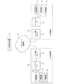
図1は、本実施形態にかかるIP電話システムの全体構成を示す図である。図1に示すように、このシステムは、VoIP網制御装置10とIP電話機70を有する複数のLAN(Local Area Network)通信網20とをインターネット通信網90により接続している。インターネット通信網90は、TCP/IPに従った手順でパケットをルーティングする各ノードと、それらを接続する電話回線とを含む。
FIG. 1 is a diagram showing an overall configuration of an IP telephone system according to the present embodiment. As shown in FIG. 1, in this system, a VoIP
VoIP網制御装置10は、MPU(Micro Processing Unit)、RAM(Random Access Memory)、ROM(Read Only Memory)、ハードディスク、ネットワークインターフェースなどを備えたコンピュータである。VoIP網制御装置10は、各IP電話機70のIPアドレスと電話番号の相互の変換処理、通信帯域処理、輻輳処理などの各処理を行うことにより、それらのIP電話機70間の通話を支援する。
The VoIP
LAN通信網20の各々は、信号中継装置となるスイッチングハブ50を間に挟んでルータ型モデム30と複数のIP電話機70(「端末」に相当)とをケーブル接続することにより構築されている。IP電話機70の各々は、SIP(Session Initiation Protocol)に準拠した各処理の手順を記したプログラム(以下、「SIPプログラム」と呼ぶ)を実装している。そして、それらのIP電話機70は、VoIP網制御装置10による支援の下、スイッチングハブ50、ルータ型モデム30、およびインターネット通信網90を介して別のLAN通信網20のIP電話機70と各種メッセージのパケットを送受信し、そのIP電話機70との間にセッションを確立する。あるIP電話機70と別のLAN通信網20のIP電話機70との間にセッションが確立されると、以降の音声データのパケットの送受信を通じて通話が実現される。以降の説明において、インターネット通信網90からLAN通信網20の末端のIP電話機70へ向かうパケットの下り方向を適宜「ダウンリンク」と呼び、IP電話機70からインターネット通信網90へ向かうパケットの上り方向を適宜「アップリンク」と呼ぶ。
Each of the
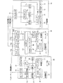
図2は、LAN通信網20を構築する、ルータ型モデム30、スイッチングハブ50、IP電話機70のハードウェア構成を示す図である。
FIG. 2 is a diagram illustrating a hardware configuration of the
図2に示すように、ルータ型モデム30は、受電端子31、給電部32、RJ11コネクタ33、RJ45コネクタ34、ADSL(Asymmetric Digital Subscriber Line)信号変換回路35、PHYチップ(Physical Layer Chip)36、ROM37、MPU38、RAM39を有する。これら各部のうち、給電部32、ADSL信号変換回路35、PHYチップ36、ROM37、MPU38、RAM39は、略直方体の筐体(図示せず)に内蔵される。また、RJ11コネクタ33とRJ45コネクタ34は、筐体の背面から外部に向かって露出しており、受電端子31は、その筐体に設けた孔から外部に引き出された電源ケーブルと接続されている。
As shown in FIG. 2, the router-
受電端子31は、コンセントプラグであり、カバー(図示せず)の前端に穿設した孔から一対の金属製の栓刃を吐出させるとともに、その栓刃と電源ケーブル内の電線の一端とを繋いだ構造をなしている。この受電端子31の栓刃を商用交流電源(図示せず)のプラグソケットに挿入すると、その商用交流電源から電源ケーブルを介して給電部32へ交流電力が供給される。給電部32は、AC/DCコンバータ40、バッテリ41を有する。AC/DCコンバータ40は、商用交流電源から供給される交流電力を直流電力に変換する。変換により得られた直流電力は、電線を介して各部へ供給されるとともに、バッテリ41に蓄電される。停電などの事情によって交流電力の供給が止まり、または、その電力品質のレベル低下が発生すると、バッテリ41に蓄電された電力が各部へ供給される。
The
RJ11コネクタ33は、モデムケーブルを介してインターネット通信網90と接続されている。一方、RJ45コネクタ34は、スイッチングハブ50のRJ45コネクタ53a(後述)とUTP(Unshielded Twist Pair)ケーブルを介して接続される。
The
ADSL信号変換回路35は、RJ11コネクタ33から供給されるアナログ信号を変換して得たイーサネット(登録商標)フレーム(以下、単に「フレーム」と呼ぶ)のコード列をMPU38へ供給するとともに、MPU38から供給されるフレームのコード列を変換して得たアナログ信号をRJ11コネクタ33へ供給する。また、PHYチップ36は、RJ45コネクタ34から供給されるデジタル信号を変換して得たフレームのコード列をMPU38へ供給し、MPU38から供給されるフレームのコード列を変換して得たデジタル信号をRJ45コネクタ34へ供給する。
The ADSL
図3は、フレームのデータ構造の概要を示す図である。フレームは、TCP/IPのアプリケーション層のプログラム(例えば、SIPプログラム)に引き渡されるデータ91の前段に、UDPヘッダ92、IPヘッダ93、およびフレームヘッダ94を付加した構造をなしている。このフレームのフレームヘッダ94を除いた部分が「パケット」に相当する。
FIG. 3 is a diagram showing an outline of the data structure of the frame. The frame has a structure in which a
UDPヘッダ92は、データの送信元のアプリケーション層のプログラムに固有のポート番号を示す宛先ポート番号や、その宛先のプログラムに固有のポート番号を示す発信元ポート番号を示すコード列を内包する。IPヘッダ93は、パケットの送信元の送信元IPアドレスやその宛先の宛先IPアドレスを示すコード列を内包する。フレームヘッダ94は、フレームの送信元の送信元MAC(Media Access Control)アドレスやその宛先の宛先MACアドレスなどを示すコード列を内包する。
The
図2において、ROM37には、パケットのルーティングに関わる処理の手順などを記したプログラムが記憶される。そのプログラムを実行するMPU38は、自らがダウンリンク側に従えたIP電話機70へのIPアドレス(プライベートIPアドレス)の割り当て、ルーティングテーブルやアドレス管理テーブルのRAM39への書き込み、フレームに含まれるMACアドレスやポート番号の書き換え、などといった処理を行う。
In FIG. 2, the
MPU38は、ADSL信号変換回路35からフレームのコード列が供給されると、そのフレームのIPヘッダ93の宛先IPアドレスを基に割り出したパケットの宛先が、自らがダウンリンク側に従えたIP電話機70のいずれかであるかを判断する。そして、いずれかのIP電話機70を宛先とするパケットを含むフレームであるときは、宛先MACアドレスを自らのMACアドレスからパケットの宛先(IP電話機70)のそれに書き換えたフレームのコード列を、PHYチップ36へ供給する。PHYチップ36に供給されたフレームのコード列はデジタル信号に変換された上でRJ45コネクタ34からスイッチングハブ50へ送出され、その宛先のIP電話機70へ転送される
When the
また、MPU38は、PHYチップ36からフレームのコード列が供給されると、そのフレームのIPヘッダ93の宛先IPアドレスを基に割り出したパケットの宛先が、自らのアップリンク側のノード(例えば、VoIP網制御装置10)であるか否かを判断する。そして、アップリンク側のノードを宛先とするパケットを含むフレームであるときは、宛先MACアドレスを自らのMACアドレスからその宛先に至る転送ルート上の直近のノードのそれに書き換えたフレームのコード列を、ADSL信号変換回路35へ供給する。ADSL信号変換回路35へ供給されたフレームのコード列はアナログ信号に変換された上でRJ11コネクタ33から公衆回線へ送出され、その宛先のノードまで転送される。
Further, when the
スイッチングハブ50は、図2に示すように、受電端子51、給電部52、複数のRJ45コネクタ53a〜53d(以下、適宜「RJ45コネクタ53」と記す)、トランス54、PHYチップ55、スイッチングIC(Integrated Circuit:「第1のスイッチング素子」に相当)56、RAM57を有する。これら各部のうち、給電部52、トランス54、PHYチップ55、スイッチングIC56、RAM57は、略直方体の筐体(図示せず)に内蔵される。また、RJ45コネクタ53は、筐体の背面から外部に向かって露出しており、受電端子51は、その筐体に設けた孔から外部に引き出された電源ケーブルと接続されている。
As shown in FIG. 2, the switching
受電端子51は、ルータ型モデム30のそれと同様の構造をなすコンセントプラグである。よって、この受電端子51の栓刃を商用交流電源のプラグソケットに挿入すると、その商用交流電源から電源ケーブルを介して給電部52へ交流電力が供給される。給電部52は、AC/DCコンバータ58、バッテリ59(「蓄電手段」に相当)を有し、各々の構造はルータ型モデム30のそれと同様である。
The
複数のRJ45コネクタ53のうちの1つであるRJ45コネクタ53aは、ルータ型モデム30用として確保され、ルータ型モデム30のRJ45コネクタ34とUTPケーブルを介して接続される。また、残りのRJ45コネクタ53b〜dは、各IP電話機70用としてそれぞれ確保され、各IP電話機70のRJ45コネクタ71(後述)の各々とUTPケーブルを介して接続される。
The
図2に示すように、スイッチングハブ50の給電部52のAC/DCコンバータ58およびバッテリ59は、PHYチップ55、スイッチングIC56、RAM57の各素子と電線により繋がっており、その電線を介してAC/DCコンバータ58やバッテリ59から各素子へ電力が供給される。さらに、AC/DCコンバータ58およびバッテリ59は、トランス54を介してIP電話機70用のRJ45コネクタ53b〜53dの一部の端子(後述)とも電線により繋がっており、その端子からIP電話機70へも電力が供給される。
As shown in FIG. 2, the AC /
図4は、RJ45コネクタ53b〜53d、71の端子配列と、それらの両コネクタを接続するUTPケーブル95の断面構造とを示す図である。図4に示すように、RJ45コネクタ53b〜53d,71は、1から8の番号を割り振った8つの端子を配列した構造をなしている。ルータ型モデム30のRJ45コネクタ53b〜53dは、デジタル信号の送信用として1番と2番の端子が、受信用として3番と6番の端子が割り当てられたMDI(Medium Dependent Interface)−Xタイプとなっている。一方、後述するIP電話機70のRJ45コネクタ71は、デジタル信号の受信用として1番と2番の端子が、送信用として3番と6番の端子が割り当てられたMDIタイプとなっている。そして、本実施形態では、デジタル信号の送信用と受信用のいずれにも割り当てられていない、RJ45コネクタ53b〜53dの7番と8番の端子(「残余端子」に相当)を、電線によりAC/DCコンバータ58およびバッテリ59と繋いでいる。よって、スイッチングハブ50のRJ45コネクタ53b〜53dとIP電話機70のRJ45コネクタ71に、8本の電線を2本ずつ一組にしてより合わせたストレートタイプのUTPケーブル95の端を接続することにより、1番、2番、3番、6番の端子(「パケット用端子」に相当)を介してデジタル信号を送受信させるだけでなく、7番と8番の端子を介してスイッチングハブ50からIP電話機70へ電力を供給することができる。
FIG. 4 is a diagram showing a terminal arrangement of the
図2の説明に戻る。スイッチングハブ50のPHYチップ55は、RJ45コネクタ53a〜53dから供給されるデジタル信号を変換して得たフレームのコード列をスイッチングIC56へ供給し、スイッチングIC56から供給されるフレームのコード列を変換して得たデジタル信号をそのスイッチングIC56が指定するRJ45コネクタ53a〜53dへ供給する。
Returning to the description of FIG. The
スイッチングIC56は、RAM57へのアドレス管理テーブルの書き込み、そのアドレス管理テーブルに従ったフレームの送出、などといった処理を行う。スイッチングIC56は、PHYチップ55から供給されるフレームのコード列をRAM57に記憶させた上でそのフレームの宛先MACアドレスを特定する。そして、特定した宛先MACアドレスが示すIP電話機70またはルータ型モデム30が接続されたRJ45コネクタ53を送出先として指示した上で、そのフレームのコード列をPHYチップ55へ供給する。PHYチップ55に供給されたフレームのコード列はデジタル信号に変換され、指示にかかるRJ45コネクタ53からIP電話機70またはルータ型モデム30へ送出される。
The switching
IP電話機70は、RJ45コネクタ71、PHYチップ72、ROM73、MPU74、RAM75、マイクロホン76、スピーカ77、LCD(Liquid Crystal Display)78、タッチキー79、コーデック80を有する。これら各部のうち、PHYチップ72、ROM73、MPU74、RAM75、コーデック80は、略直方体の筐体(図示せず)に内包され、RJ45コネクタ71、LCD78、タッチキー79は、筐体の背面または前面から外部に露出されている。さらに、マイクロホン76とスピーカ77は、受話器(図示せず)に収容されている。また、PHYチップ72、ROM73、MPU74、コーデック80の各部は、RJ45コネクタ71の7番と8番の端子と電線により繋がっており、それらの両端子を介してスイッチングハブ50から電力が各部へ供給される。このため、IP電話機70には給電部が搭載されていない。
The
RJ45コネクタ71は、MDIタイプの端子配列を有するコネクタであり、その7番と8番の端子を介してスイッチングハブ50から電力の供給を受け得ることは上述したところである。
The
LCD78は、MPU74による制御の下、各種情報を表示する。また、タッチキー79は、ダイヤルキーなどを有し、各々の押下操作を検出したことを示す信号をMPU74へ供給する。
The
マイクロホン76は、自らが収音した音の音声信号をコーデック80へ供給する。スピーカ77は、コーデック80から供給される音声信号に応じた音を放音する。コーデック80は、音声信号から音声データへの符号化、および音声データから音声信号への復号化を司る。
The
PHYチップ72は、RJ45コネクタ71から供給されるデジタル信号を変換して得たフレームのコード列をMPU74へ供給し、MPU74から供給されるフレームのコード列を変換して得たデジタル信号をRJ45コネクタ71へ供給する。
The
ROM73には、自機に固有の電話番号やSIPプログラムなどが記憶される。そのプログラムを実行するMPU74は、別のLAN通信網20のIP電話機70とセッションを確立し、そのIP電話機70との間で音声データを内包するパケットを送受信することにより、通話を実現する。
The
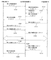
図5は、2つのIP電話機70間で通話のためのセッションを確立し、それを解消して通話を終えるまでの手順を示すシーケンス図である。なお、この図5において、発呼元となるIP電話機70をIP電話機70Aとし、発呼先となるIP電話機70をIP電話機70Bとする。
FIG. 5 is a sequence diagram showing a procedure from establishing a session for a call between two
まず、受話器を上げるなどの操作によりオフフック状態となった発呼元のIP電話機70Aへ、タッチキー79の操作を通じて発呼先の電話番号が入力される。電話番号の入力を受けたIP電話機70Aは、VoIP網制御装置10のIPアドレスに宛てた第1の呼設定要求メッセージのパケットを送信する(S100)。第1の呼設定要求メッセージのパケットを受信したVoIP網制御装置10は、IP電話機70BのIPアドレスに宛てた第2の呼設定要求メッセージのパケットを送信する(S110)。VoIP網制御装置10は、各IP電話機70の各々のIPアドレスと電話番号を対応付けたVoIP管理テーブル(図示せず)を有している。そして、第1の呼接続設定要求に含まれる電話番号を基にそのVoIP管理テーブルを参照することにより、第2の呼設定要求メッセージの宛先となるIP電話機70BのIPアドレスを特定する。
First, the telephone number of the callee is input through the operation of the
第2の呼設定要求メッセージのパケットを受信したIP電話機70Bは、VoIP網制御装置10のIPアドレスに宛てた呼設定受付メッセージのパケットを送信するとともに(S120)、VoIP網制御装置10に宛てた第1の呼出制御メッセージのパケットを送信する(S130)。呼設定受付メッセージのパケットを受信したVoIP網制御装置10は、IP電話機70AのIPアドレスに宛てた第2の呼出制御メッセージのパケットを送信する(S140)。なお、呼設定受付メッセージは、発呼が受け付けられて呼び出しが開始されたことを示すメッセージであり、第1の呼出制御メッセージおよび第2の呼出制御メッセージは、発呼先で呼び出しが行われているもののオフフック状態にはなっていないことを示すメッセージである。
The IP telephone 70B that has received the second call setting request message packet transmits a call setting acceptance message packet addressed to the IP address of the VoIP network control device 10 (S120), and is addressed to the VoIP network control device 10 A packet of the first call control message is transmitted (S130). The VoIP
この後、発呼先のIP電話機70Bが、受話器を上げるなどの操作によりオフフック状態になると、そのIP電話機70Bは、VoIP網制御装置10に宛てた第1の応答メッセージのパケットを送信する(ステップS150)。第1の応答メッセージのパケットを受信したVoIP網制御装置10は、IP電話機70AのIPアドレスに宛てた第2の応答メッセージのパケットを送信する(ステップS160)。
Thereafter, when the IP telephone 70B as the call destination enters an off-hook state by an operation such as raising the handset, the IP telephone 70B transmits a packet of the first response message addressed to the VoIP network control device 10 (step S150). The VoIP
第2の応答メッセージのパケットを受信したIP電話機70Aは、VoIP網制御装置10のIPアドレスに宛てた第1の確認応答メッセージのパケットを送信する(S170)。第1の確認応答メッセージのパケットを受信したVoIP網制御装置10は、IP電話機70BのIPアドレスに宛てた第2の確認応答メッセージのパケットを送信する(S180)。
The IP telephone 70A that has received the second response message packet transmits the first confirmation response message packet addressed to the IP address of the VoIP network control device 10 (S170). Upon receiving the first acknowledgment message packet, the VoIP
IP電話機70Bが、第2の確認応答メッセージのパケットを受信すると、IP電話機70Bには音声データを含むパケットを受け入れるためのポートが確保され、そのポートとIP電話機70Aの側に確保されているポートの間との通信接続が確立する。そして、以降は、IP電話機70A,70Bのマイクロホン76が収音した音声の音声データを含むパケットが両ポート間で送受信され、通話が実現する。
When IP telephone 70B receives the second acknowledgment message packet, IP telephone 70B has a port for accepting a packet containing voice data, and the port secured on the IP telephone 70A side. A communication connection with is established. Thereafter, a packet including voice data of voice picked up by the
一方のIP電話機70(図5ではIP電話機70A)が、受話器を置くなどの操作によりオンフック状態になると、そのIP電話機70Aは、VoIP網制御装置10のIPアドレスに宛てた第1の切断メッセージのパケットを送信する(S190)。第1の切断メッセージのパケットを受信したVoIP網制御装置10では、IP電話機70BのIPアドレスに宛てた第2の切断メッセージのパケットを送信する(S200)。ここで、IP電話機70A,Bは、各々のRJ45コネクタ71の7番と8番の端子を介してスイッチングハブ50から電力の供給を受けており、電力の供給元となるスイッチングハブ50は、受電端子51から供給される電力を蓄電するバッテリ59を搭載している。よって、停電により商用交流電源からの電力の供給が止まっても、各IP電話機70A,Bは、上述した各メッセージを送受信してセッションを確立し、通話を実現できる。
When one of the IP telephones 70 (IP telephone 70A in FIG. 5) enters an on-hook state by an operation such as placing a handset, the IP telephone 70A receives the first disconnect message addressed to the IP address of the VoIP
第2の切断メッセージのパケットを受信したIP電話機70Bは、VoIP網制御装置10のIPアドレスに宛てた第1の切断応答メッセージのパケットを送信する(S210)。第1の切断応答メッセージのパケットを受信したVoIP網制御装置10は、IP電話機70AのIPアドレスに宛てた第2の切断応答メッセージのパケットを送信する(S220)。IP電話機70Aが、第2の切断応答メッセージのパケットを受信すると、そのIP電話機70AとIP電話機70Bのポート間の通信接続が解除され、通話が終了する。
The IP telephone set 70B that has received the second disconnect message packet transmits a first disconnect response message packet addressed to the IP address of the VoIP network control device 10 (S210). The VoIP
以上説明した本実施形態では、バックアップ電力を蓄電するバッテリ41,59をルータ型モデム30とスイッチングハブ50に搭載し、且つ、スイッチングハブ50の電力をそのRJ45コネクタ53b〜53dの7番と8番の端子を介してIP電話機70へ供給し得るようになっている。よって、停電の発生により商用交流電源からの電力の供給が停止した場合でも、ルータ型モデム30、スイッチングハブ50、さらにはIP電話機70の各部へバッテリ41,59から電力を供給することにより、IP電話サービスを継続して利用することができる。
In the present embodiment described above, the
(第2実施形態)
本発明の第2実施形態について、以下、図面を参照しながら説明する。第1実施形態にかかるスイッチングハブ50は、IP電話機70用の各RJ45コネクタ53b〜53dがバッテリ59と電線により繋がっており、停電が発生すると、バッテリ59からそれらのRJ45コネクタ53b〜53dを介して各IP電話機70へ電力がほぼ均等に供給されるようになっている。これに対し、本実施形態にかかるスイッチングハブ50は、RJ45コネクタ53b〜53dとバッテリ59との間にスイッチを介挿する。そして、停電が発生すると、それらのスイッチを個別に切り換えることによって一部のIP電話機70への電力の供給を制限し、電力の供給を制限するIP電話機70への発呼があったとき、その発呼の転送を要求するメッセージのパケットをVoIP網制御装置10に宛てて送信する。
(Second Embodiment)
A second embodiment of the present invention will be described below with reference to the drawings. In the switching
本実施形態にかかるIP電話システムの、VoIP網制御装置10、ルータ型モデム30、およびIP電話機70のハードウェア構成は、第1実施形態と同様であり、再度の説明を割愛する。
The hardware configurations of the VoIP
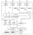
図6は、第2実施形態にかかる信号中継装置となるスイッチングハブ50のハードウェア構成を示す図である。図6に示すように、このスイッチングハブ50は、受電端子51、給電部52、複数のRJ45コネクタ53a〜53d、トランス54、PHYチップ55、スイッチングIC56、RAM57に加えて、タイマ60、電圧検出部61(「検出手段」に相当)、制御部62(「制御手段」に相当)を有する。また、AC/DCコンバータ58およびバッテリ59とRJ45コネクタ53b〜53dの各々とを繋ぐ電線には、スイッチ(「第2のスイッチング素子」に相当)66b〜66d(以下、適宜「スイッチ66」と記す)がそれぞれ介挿されている。そして、それらのスイッチ66b〜66dは、制御部62より供給される信号に応じて開閉する。また、タイマ60は、時間を計時する。電圧検出部61は、受電端子51に供給される交流電力の電圧を検出し、検出した電圧を示す信号を制御部62へ供給する。
FIG. 6 is a diagram illustrating a hardware configuration of the switching
制御部62は、ROM63、MPU64、RAM65を有する。そして、制御部62のROM63には、停電時における、各スイッチ66b、66c、66dの開閉や、発呼の転送を要求するメッセージの送信に関わる処理の手順を記したプログラムが記憶される。このプログラムを実行するMPU64は、IP電話機70用のRJ45コネクタ53b〜53d毎の設定データを取り纏めた設定テーブルをRAM65に生成し、停電が発生すると、その設定テーブルの内容に従って処理を行う。この設定テーブルを記憶しておくRAM65が、請求項の「メモリ」に相当する。
The
図7は、設定テーブルのデータ構造を示す図である。この設定テーブルは、各々が、IP電話機70用の各RJ45コネクタ53b〜53dと対応する複数のレコードの集合体である。このテーブルをなすレコードの各々は、「ポート」、「給電時間」、「電話番号」、「IPアドレス」、「発呼転送先」の5つのフィールドを有する。「ポート」のフィールドには、各JR45コネクタに固有のコネクタポート番号が記憶される。「給電時間」のフィールドには、給電時間データが記憶される。給電時間データは、バッテリ59に蓄電された電力の供給を開始してからその供給を停止するまでの時間を示すデータである。この給電時間データは、各RJ45コネクタ53b〜53dに接続されるIP電話機70の重要度、使用頻度などを考慮して個別に設定されることが望ましい。「電話番号」のフィールドには、各IP電話機70の電話番号を示すデータが記憶される。「IPアドレス」のフィールドには、各RJ45コネクタ53b〜53dに接続されたIP電話機70のIPアドレス(プライベートIPアドレス)が記憶される。「発呼転送先」のフィールドには、転送先データが記憶される。転送先データは、電力の供給が止まったIP電話機70への発呼があった際の転送先を示すデータである。転送先を示すデータは、固定電話や携帯電話の電話番号であってもよいし、別のLAN通信網20のIP電話機70のIPアドレス(グローバルIPアドレス)であってもよい。
FIG. 7 is a diagram illustrating a data structure of the setting table. This setting table is an aggregate of a plurality of records each corresponding to each
図8は、スイッチングハブ50の制御部62が実行する特徴的な処理を示すフローチャートである。スイッチングハブ50の制御部62は、電圧検出部61から供給される信号を基に、停電の発生の有無を監視する。そして、停電が発生したと判断すると(S300:Yes)、タイマ60へ計時の開始を指示する信号を供給する(S310)。信号の供給を受けたタイマ60は、その時からの経過時間を示す信号を制御部62へ逐次供給する。
FIG. 8 is a flowchart showing characteristic processing executed by the
計時の開始を指示する信号をタイマ60へ供給した制御部62は、タイマ60による支援の下、設定テーブルのいずれかのレコードの「給電時間」のフィールドの給電時間データが示す時間が経過したか否かを判断する(S320)。
The
給電時間データが示す時間が経過したと判断した制御部62は(S320:Yes)、その給電時間データを記憶したレコードを設定テーブルから特定する(S330)。続いて、ステップS330で特定したレコードの「電話番号」のフィールドに記憶された電話番号、「IPアドレス」のフィールドに記憶されたIPアドレス、および、「発呼転送先」のフィールドに記憶された転送先データを含むVoIP網制御装置10宛ての転送設定要求メッセージのパケットを生成する(S340)。さらに、そのパケットを内包し、且つルータ型モデム30のMACアドレスを宛先MACアドレスとして埋め込んだフレームのコード列を、PHYチップ55へ供給する(S350)。そのフレームのコード列は、PHYチップ55によるデジタル信号への変換を経てRJ45コネクタ53aからルータ型モデム30へ送出される。さらに、そのフレームはルータ型モデム30による変換を経てインターネット通信網90へ送出され、VoIP網制御装置10まで転送される。
When determining that the time indicated by the power supply time data has elapsed (S320: Yes), the
転送設定要求メッセージのパケットを受信したVoIP網制御装置10は、その転送設定要求メッセージに含まれる電話番号とIPアドレスの対を自らのVoIP管理テーブルから特定し、特定した対のIPアドレスを転送設定要求メッセージに含まれる転送先データと置き換える。この置き換え以降、VoIP網制御装置10がその対の電話番号を含む第1の呼設定要求メッセージ(図5のS100)を受信した場合、転送先データが示す固定電話や携帯電話の番号などを基に第2の呼設定要求メッセージ(図5のS110)の宛先が特定されることになる。また、転送先データをIPアドレスと置き換えたVoIP網制御装置10は、転送設定要求メッセージの送信元に宛てた設定完了メッセージのパケットを送信する。
Upon receiving the packet of the transfer setting request message, the VoIP
転送設定要求メッセージのパケットを送信した後、スイッチングハブ50の制御部62は、設定完了メッセージの返信を待ち、その設定完了メッセージのパケットを含むフレームのコード列がPHYチップ55から供給されると(S360:Yes)、ステップS330で特定したレコードの「ポート」のフィールドのコネクタポート番号と対応するRJ45コネクタ53のスイッチ66(例えば、RJ45コネクタ53bのスイッチ66b)へ、信号(開信号)を供給する(S370)。信号(開信号)の供給を受けたスイッチ66が閉状態から開状態に変わると、バッテリ59からそのRJ45コネクタ53に接続されたIP電話機70への電力の供給が停止される。スイッチ66へ信号(開信号)を供給した制御部62は、ステップS320に戻り、別のレコードの「給電時間」のフィールドの給電時間データが示す時間の経過の有無に応じて以降の処理を行う。
After transmitting the packet of the transfer setting request message, the
以上説明した第2実施形態にかかるスイッチングハブ50は、停電が発生すると、設定テーブルにて設定された給電時間が経過したIP電話機70から順に、電力の供給を停止する。よって、ほとんど使われないIP電話機70への電力の供給は早急に停止させる一方で使われる頻度の極めて高いIP電話機70へはより長い時間に渡って電力を供給することにより、バッテリ59を長持ちさせることができる。また、電力の給電時間が経過したIP電話機70については、転送設定要求メッセージをVoIP網制御装置10へ送信し、設定完了メッセージの返信を受けてから電力の供給を停止する。よって、電力の供給が停止されたIP電話機70に対する発呼がエラーになる事態の発生を回避できる。
When a power failure occurs, the switching
(他の実施形態)
本発明は、上述の各実施形態に限定されることなく、種々の変形実施が可能である。
(Other embodiments)
The present invention is not limited to the above-described embodiments, and various modifications can be made.
上記実施形態は、スイッチングハブ50のバッテリ59に蓄電されたバックアップ電力を、RJ45コネクタ53b〜53dを介して各IP電話機70へ供給するようになっている。これに対し、ルータ型モデム30のRJ45コネクタ34にIP電話機70を接続し、ルータ型モデム30のバッテリ41に蓄電されたバックアップ電力をRJ45コネクタ34を介してIP電話機70へ供給するようにしてもよい。このとき、ルータ型モデム30は、信号中継装置となる。また、IP電話機70とインターネット通信網90の間に介在し、インターネット通信網90のノードから転送されるパケットをIP電話機70へ中継でき、且つ商用交流電源から自身に供給される交流電力を基にバックアップ電力を蓄電できる構成にさえなっていれば、それ自身が信号中継装置となるブリッジやモデムなどの他のネットワーク機器にIP電話機70を接続してもよい。
In the above embodiment, the backup power stored in the
第2実施形態では、給電時間が経過すると、転送設定要求メッセージをVoIP網制御装置10へ送信し、その転送設定要求メッセージに対する設定完了メッセージの返信を受けたIP電話機70から順に、電力の供給を停止するようになっている。これに対し、この方式に代えて、または、この方式とともに、あるIP電話機70が接続されたRJ45コネクタ53b〜53dの給電時間が経過すると、電力の供給の停止を予告する音声データのパケットをそのIP電話機70へ供給し、スピーカ77からその予告の音声を放音させるようにしてもよい。同様に、電力の供給の停止を予告する文字列のテキストデータのパケットをそのIP電話機70へ供給し、LCD78にその文字列を表示させるようにしてもよい。この表示を上述の各方法に代えて、または、いずれか1つとともに、もしくは、全ての方法とともに行うようにしてもよい。
In the second embodiment, when the power supply time elapses, a transfer setting request message is transmitted to the VoIP
信号中継装置に接続される末端の装置としては、IP電話機70のほかに、通常の固定電話機としてもよい。
The terminal device connected to the signal relay device may be an ordinary fixed telephone in addition to the
10…VoIP網制御装置、20…LAN通信網、30…ルータ型モデム、31,51…受電端子、32,52…給電部、33…RJ11コネクタ、34,53,71…RJ45コネクタ、35…ADSL信号変換回路、36,55,72…PHYチップ、37,63,73…ROM、38,64,74…MPU、39,57,65,75…RAM、40,58…AC/DCコンバータ、41,59…バッテリ(「蓄電手段」に相当)、50…スイッチングハブ(「信号中継装置」に相当)、54…トランス、56…スイッチングIC(「第1のスイッチング素子」に相当)、60…タイマ、61…電圧検出部(「検出手段」に相当)、62…制御部(「制御手段」に相当)、66…スイッチ(「第2のスイッチング素子」に相当)、70…IP電話機(「端末」に相当)、76…マイクロホン、77…スピーカ、78…LCD、79…タッチキー、80…コーデック、90…インターネット通信網、91…データ、92…UDPヘッダ、93…IPヘッダ、94…フレームヘッダ
DESCRIPTION OF
Claims (4)
パケットなどの信号を入出力するための端子を含む複数の端子を有する複数のコネクタであって、各々の上記端子同士が電線により繋がる複数のコネクタと、
上記受電端子と電線により繋がった手段であって、その電線を介して上記受電端子から供給される交流電力を基に、上記複数のコネクタの一部または全部に繋がる電線へ放電するためのバックアップ電力を蓄電する蓄電手段と、
を備えることを特徴とする信号中継装置。 A power receiving terminal connected to an AC power source;
A plurality of connectors including a plurality of terminals including terminals for inputting and outputting signals such as packets, and a plurality of connectors in which each of the terminals is connected by an electric wire;
Backup power for discharging to a wire connected to some or all of the plurality of connectors based on the AC power supplied from the power receiving terminal via the wire, the means being connected by the power receiving terminal and the wire Power storage means for storing
A signal relay device comprising:
をさらに備えることを特徴とする請求項1に記載の信号中継装置。 An element inserted in an electric wire connecting the terminals of the plurality of connectors, and a different connector is selected according to a telephone that is a destination of a packet indicated by a signal input from a terminal of a certain connector, and the selected connector A first switching element for sending a signal to an electric wire connected to
The signal relay device according to claim 1, further comprising:
パケットを示す信号を入出力するためのパケット用端子と、パケットを示す信号を入出力しない残余端子とを有し、
前記複数のコネクタの上記残余端子に繋がる電線の各々と前記蓄電手段に繋がる電線との間に介挿された素子であって、それらの各コネクタの上記残余端子に繋がる電線と前記蓄電手段に繋がる電線との接続の有無を個別に切り換える第2のスイッチング素子、
をさらに備えることを特徴とする請求項2に記載の信号中継装置。 Each of the plurality of connectors is
A packet terminal for inputting / outputting a signal indicating a packet, and a remaining terminal not inputting / outputting a signal indicating a packet;
An element inserted between each of the electric wires connected to the remaining terminals of the plurality of connectors and the electric wires connected to the power storage means, and connected to the power storage means and the electric wires connected to the remaining terminals of the respective connectors. A second switching element for individually switching presence / absence of connection with the electric wire,
The signal relay device according to claim 2, further comprising:
前記受電端子から供給される交流電力の電圧を検出する検出手段と、
前記検出手段が検出した電圧が所定の条件を満たすとき、前記複数のコネクタのうちの一部のコネクタの前記残余端子に繋がる電線と前記蓄電手段に繋がる電線との接続を指示する信号を前記第2のスイッチング素子へ供給するとともに、その残りのコネクタに接続された一または複数の端末の端末アドレスと対応する転送先データを前記メモリから特定し、特定した転送先データを含む転送要求メッセージを示すパケットを、端末が接続されていない前記コネクタを介して出力する制御手段と、
をさらに備えることを特徴とする請求項3に記載の信号中継装置。 A memory that associates and stores a terminal address of a terminal connected to any of the plurality of connectors and transfer destination data indicating a transfer destination of a packet addressed to the terminal address;
Detecting means for detecting the voltage of the AC power supplied from the power receiving terminal;
When the voltage detected by the detection means satisfies a predetermined condition, a signal instructing connection between an electric wire connected to the remaining terminal of a part of the plurality of connectors and an electric wire connected to the power storage means is 2 shows the transfer request message including the specified transfer destination data, specifying the transfer destination data corresponding to the terminal address of one or a plurality of terminals connected to the remaining switching elements from the memory. Control means for outputting a packet via the connector to which a terminal is not connected;
The signal relay device according to claim 3, further comprising:
Priority Applications (3)
| Application Number | Priority Date | Filing Date | Title |
|---|---|---|---|
| JP2007170257A JP4764994B2 (en) | 2007-06-28 | 2007-06-28 | Signal relay device |
| PCT/JP2008/061016 WO2009001709A1 (en) | 2007-06-28 | 2008-06-17 | Signal relay device |
| US12/665,647 US8223674B2 (en) | 2007-06-28 | 2008-06-17 | Signal relay device |
Applications Claiming Priority (1)
| Application Number | Priority Date | Filing Date | Title |
|---|---|---|---|
| JP2007170257A JP4764994B2 (en) | 2007-06-28 | 2007-06-28 | Signal relay device |
Publications (2)
| Publication Number | Publication Date |
|---|---|
| JP2009010706A true JP2009010706A (en) | 2009-01-15 |
| JP4764994B2 JP4764994B2 (en) | 2011-09-07 |
Family
ID=40185527
Family Applications (1)
| Application Number | Title | Priority Date | Filing Date |
|---|---|---|---|
| JP2007170257A Expired - Fee Related JP4764994B2 (en) | 2007-06-28 | 2007-06-28 | Signal relay device |
Country Status (3)
| Country | Link |
|---|---|
| US (1) | US8223674B2 (en) |
| JP (1) | JP4764994B2 (en) |
| WO (1) | WO2009001709A1 (en) |
Cited By (4)
| Publication number | Priority date | Publication date | Assignee | Title |
|---|---|---|---|---|
| JP2015173360A (en) * | 2014-03-11 | 2015-10-01 | 株式会社ナカヨ | Telephone system having flexible power outage response function |
| JP2015192358A (en) * | 2014-03-28 | 2015-11-02 | 株式会社ナカヨ | Communication system having outage time power supply control function |
| JP2017163275A (en) * | 2016-03-08 | 2017-09-14 | 株式会社ナカヨ | Communication system with power-failure-time preferential power supply function |
| JP2019530864A (en) * | 2016-09-19 | 2019-10-24 | パンドウィット・コーポレーション | Voltage indicator display module |
Families Citing this family (4)
| Publication number | Priority date | Publication date | Assignee | Title |
|---|---|---|---|---|
| EP2449693A2 (en) * | 2009-06-29 | 2012-05-09 | Sigma Designs Israel S.D.I Ltd. | Power line communication method and apparatus |
| KR101688857B1 (en) * | 2010-05-13 | 2016-12-23 | 삼성전자주식회사 | Terminal for contents centric network and method of communication for terminal and herb in contents centric network(ccn) |
| EP2787693B1 (en) | 2013-04-05 | 2015-12-09 | Telefonaktiebolaget L M Ericsson (publ) | User plane traffic handling using network address translation and request redirection |
| US10637993B1 (en) * | 2016-09-26 | 2020-04-28 | Aquantia Corp. | High-bandwidth home network over phone line |
Citations (2)
| Publication number | Priority date | Publication date | Assignee | Title |
|---|---|---|---|---|
| JP2005159617A (en) * | 2003-11-25 | 2005-06-16 | Chugoku Electric Power Co Inc:The | Telephone communication system |
| JP2007060802A (en) * | 2005-08-24 | 2007-03-08 | Densei Lambda Kk | Uninterruptible power supply |
Family Cites Families (9)
| Publication number | Priority date | Publication date | Assignee | Title |
|---|---|---|---|---|
| US6181694B1 (en) * | 1998-04-03 | 2001-01-30 | Vertical Networks, Inc. | Systems and methods for multiple mode voice and data communciations using intelligently bridged TDM and packet buses |
| GB2356326B (en) * | 1999-11-12 | 2003-12-24 | Mitel Corp | Power supply for ethernet lan connected telephone |
| US7218614B1 (en) * | 2002-02-28 | 2007-05-15 | Sprint Communications Company L.P. | Calling party control for an integrated service hub |
| JP2005160055A (en) | 2003-10-31 | 2005-06-16 | Icom Inc | Ip phone terminal system, router apparatus, call control method, and program |
| JP4017592B2 (en) | 2003-12-25 | 2007-12-05 | 三洋電機株式会社 | VoIP system and VoIP telephone |
| JP2005323259A (en) | 2004-05-11 | 2005-11-17 | Nippon Telegraph & Telephone East Corp | Support system for power failure in ip telephony system, its method, its program, and its recording medium |
| EP1884062A4 (en) * | 2005-04-26 | 2014-08-20 | Accedian Networks Inc | Power over ethernet management devices and connection between ethernet devices |
| US8064473B2 (en) * | 2005-08-26 | 2011-11-22 | Ziqiang He | Local area network |
| US20070058608A1 (en) * | 2005-09-09 | 2007-03-15 | Bellsouth Intellectual Property Corporation | Telephone network architecture for a voice over internet protocol service |
-
2007
- 2007-06-28 JP JP2007170257A patent/JP4764994B2/en not_active Expired - Fee Related
-
2008
- 2008-06-17 WO PCT/JP2008/061016 patent/WO2009001709A1/en active Application Filing
- 2008-06-17 US US12/665,647 patent/US8223674B2/en not_active Expired - Fee Related
Patent Citations (2)
| Publication number | Priority date | Publication date | Assignee | Title |
|---|---|---|---|---|
| JP2005159617A (en) * | 2003-11-25 | 2005-06-16 | Chugoku Electric Power Co Inc:The | Telephone communication system |
| JP2007060802A (en) * | 2005-08-24 | 2007-03-08 | Densei Lambda Kk | Uninterruptible power supply |
Cited By (6)
| Publication number | Priority date | Publication date | Assignee | Title |
|---|---|---|---|---|
| JP2015173360A (en) * | 2014-03-11 | 2015-10-01 | 株式会社ナカヨ | Telephone system having flexible power outage response function |
| JP2015192358A (en) * | 2014-03-28 | 2015-11-02 | 株式会社ナカヨ | Communication system having outage time power supply control function |
| JP2017163275A (en) * | 2016-03-08 | 2017-09-14 | 株式会社ナカヨ | Communication system with power-failure-time preferential power supply function |
| JP2019530864A (en) * | 2016-09-19 | 2019-10-24 | パンドウィット・コーポレーション | Voltage indicator display module |
| TWI739905B (en) * | 2016-09-19 | 2021-09-21 | 美商班狄特公司 | Voltage indicator display module |
| US11378593B2 (en) | 2016-09-19 | 2022-07-05 | Panduit Corp. | Voltage indicator display module with removable battery shuttle |
Also Published As
| Publication number | Publication date |
|---|---|
| JP4764994B2 (en) | 2011-09-07 |
| US8223674B2 (en) | 2012-07-17 |
| WO2009001709A1 (en) | 2008-12-31 |
| US20100183006A1 (en) | 2010-07-22 |
Similar Documents
| Publication | Publication Date | Title |
|---|---|---|
| JP4764994B2 (en) | Signal relay device | |
| JP4756829B2 (en) | Computer telephony integration adapter | |
| US20090059907A1 (en) | System, method and device for docking station for communication device | |
| US7839990B2 (en) | System and method of generating ring back tone | |
| US20050238160A1 (en) | Enhanced Telephony Adapter Device and Methods | |
| KR20010065102A (en) | IP voice service system for voice over IP and method thereof | |
| US6870852B1 (en) | Combination router bridge in an integrated services hub | |
| JP2011091661A (en) | Telephone apparatus and telephone method | |
| JP2013115639A (en) | Telephone device and telephone system | |
| JP4836221B2 (en) | PSTN terminal accommodating device | |
| JP4355532B2 (en) | Gateway device, extension telephone exchange system, and extension telephone exchange method | |
| JP2005020676A (en) | Telephone communication method and apparatus | |
| JP4671874B2 (en) | Relay device | |
| JP2012205223A (en) | Communication apparatus | |
| JP2004320290A (en) | VoIP TELEPHONE SYSTEM AND COMMUNICATION CONTROL METHOD THEREIN | |
| DK174465B1 (en) | Dual-function telephony system and method of establishing a telephone connection | |
| JP2005191738A (en) | Gateway apparatus and program therefor | |
| JPWO2006090788A1 (en) | Polarity control system, access gateway, and polarity control method | |
| JP2004320382A (en) | Lan telephone system | |
| JP6623669B2 (en) | Communication device, communication program, communication method, and communication system | |
| JP2003179689A (en) | Method and apparatus for switching line, and network equipment | |
| JP2004056775A (en) | Voip telephone system | |
| JP5071639B2 (en) | VoIP telephone system, transfer processing method and transfer processing program in VoIP telephone system | |
| JP5417791B2 (en) | Network system and telephone terminal call state acquisition method | |
| JP2003298735A (en) | Terminal and program |
Legal Events
| Date | Code | Title | Description |
|---|---|---|---|
| A621 | Written request for application examination |
Free format text: JAPANESE INTERMEDIATE CODE: A621 Effective date: 20090311 |
|
| A711 | Notification of change in applicant |
Free format text: JAPANESE INTERMEDIATE CODE: A712 Effective date: 20100423 |
|
| RD04 | Notification of resignation of power of attorney |
Free format text: JAPANESE INTERMEDIATE CODE: A7424 Effective date: 20100423 |
|
| RD02 | Notification of acceptance of power of attorney |
Free format text: JAPANESE INTERMEDIATE CODE: A7422 Effective date: 20100507 |
|
| A131 | Notification of reasons for refusal |
Free format text: JAPANESE INTERMEDIATE CODE: A131 Effective date: 20101207 |
|
| A521 | Request for written amendment filed |
Free format text: JAPANESE INTERMEDIATE CODE: A523 Effective date: 20110202 |
|
| A01 | Written decision to grant a patent or to grant a registration (utility model) |
Free format text: JAPANESE INTERMEDIATE CODE: A01 Effective date: 20110405 |
|
| A711 | Notification of change in applicant |
Free format text: JAPANESE INTERMEDIATE CODE: A712 Effective date: 20110422 |
|
| A61 | First payment of annual fees (during grant procedure) |
Free format text: JAPANESE INTERMEDIATE CODE: A61 Effective date: 20110418 |
|
| R150 | Certificate of patent or registration of utility model |
Free format text: JAPANESE INTERMEDIATE CODE: R150 |
|
| FPAY | Renewal fee payment (event date is renewal date of database) |
Free format text: PAYMENT UNTIL: 20140624 Year of fee payment: 3 |
|
| R250 | Receipt of annual fees |
Free format text: JAPANESE INTERMEDIATE CODE: R250 |
|
| R250 | Receipt of annual fees |
Free format text: JAPANESE INTERMEDIATE CODE: R250 |
|
| R250 | Receipt of annual fees |
Free format text: JAPANESE INTERMEDIATE CODE: R250 |
|
| R250 | Receipt of annual fees |
Free format text: JAPANESE INTERMEDIATE CODE: R250 |
|
| LAPS | Cancellation because of no payment of annual fees |