JP2009002103A - Building horizontal member reinforcing implement, and construction method of building structure - Google Patents
Building horizontal member reinforcing implement, and construction method of building structure Download PDFInfo
- Publication number
- JP2009002103A JP2009002103A JP2007166185A JP2007166185A JP2009002103A JP 2009002103 A JP2009002103 A JP 2009002103A JP 2007166185 A JP2007166185 A JP 2007166185A JP 2007166185 A JP2007166185 A JP 2007166185A JP 2009002103 A JP2009002103 A JP 2009002103A
- Authority
- JP
- Japan
- Prior art keywords
- building
- cross member
- reinforcing
- reinforcing plate
- plate
- Prior art date
- Legal status (The legal status is an assumption and is not a legal conclusion. Google has not performed a legal analysis and makes no representation as to the accuracy of the status listed.)
- Granted
Links
Images


Abstract
Description
本発明は、建築用横材の強度不足を補って、例えばこの建築用横材の下方に広い間口を有するような建築構造物を構築することが可能となる建築用横材補強具、並びにこの建築用横材補強具を用いて行う建築構造物の構築方法に関するものである。 The present invention compensates for the lack of strength of a crosspiece for building, for example, a crosspiece reinforcing member for building capable of building a building structure having a wide frontage below the crosspiece for building, and this It is related with the construction method of the building structure performed using the crossing material reinforcement tool for buildings.
農家などでは、個人自らが仮設足場などの構築に用いられる単管とクランプを使用して簡易的なガレージや物置小屋などの建築構造物Bを構築しているところがある。具体的には、例えば図1に示すように、住居用の家屋19側に存する骨組(単管)を接合金具20を用いて家屋19の一側壁面に固定することで、図15に示すように家屋19に並設させて強度を保持した単管建築構造物Bを実現している。
Some farmers, for example, have built a simple building structure B such as a garage or a storage shed by using a single pipe and a clamp that are used for construction of a temporary scaffolding. Specifically, as shown in FIG. 1, for example, as shown in FIG. 15, a frame (single pipe) existing on the
このような単管を用いて構築するガレージや物置小屋は、比較的簡単に組め、専門の建築業者に依頼して建築してもらう場合に比べて非常に安価に構築できるというメリットがあるため、農家を中心に広く実施されるようになってきている。 Because the garage and storage shed constructed using such a single pipe is relatively easy to assemble and has the merit that it can be built at a very low cost compared to the case of requesting a specialized contractor to build, It has come to be widely implemented mainly by farmers.
しかしながら、このような単管建築構造物Bは、骨組材が単管であることから強度的に限界があり、この強度の問題から設計上の制約を受け、所望した通りに構築物を構築することは困難であった。 However, such a single-pipe building structure B has a limit in strength because the frame material is a single pipe, and due to this strength problem, it is subject to design restrictions and builds the structure as desired. Was difficult.
即ち、例えば長い単管を、建築用縦材3(縦設単管3A)間に架設固定する建築用横材4として使用した場合には、図16に示すようにこの横設単管4Aの途中部が強度不足により下方へ撓むように変形してしまうため、これを防止するためには支柱として機能する他の縦設単管3Aをこの横設単管4Aの途中部の下方に設置する必要があり、横設単管4A下方の間口を横設単管4Aの長さと同等に形成することは不可能であった。
That is, for example, when a long single pipe is used as a
してみると、例えば、自動車を二台横に並べて駐車できるガレージを構築する場合には、自動車の出し入れのし易さなどを考慮してガレージの出入り口(間口)を自動車二台分以上に広く確保したいが、この間口確保のために出入り口上方に長い横設単管4Aを設置すると、この横設単管4Aの強度が足りず、下方に撓んできてしまうために途中に支柱(縦設単管3A)を設置しなければならなくなり、この支柱によって出入り口が仕切られてどうしても狭い出入り口になってしまうなどの問題があった。
For example, when building a garage where two cars can be parked side by side, the garage doorway (frontage) is wider than two cars in consideration of ease of taking in and out of the car. To secure the frontage, if a long horizontal
また、農家では、収穫した多量の米などを保管しておく広い保管場所が必要であり、前記したような単管建築構造物Bにより、二階建ての物置小屋のような低コストで大容量の保管場所を確保できれば非常に有用であると考えられる。 In addition, the farmer needs a large storage place for storing a large amount of harvested rice and the like, and the single pipe building structure B as described above has a low cost and a large capacity such as a two-story storage shed. It would be very useful if a storage location could be secured.
しかし、この単管建築構造物Bは、二階建ての小屋などを作ること自体は可能であるが、上記した強度的な問題から、二階部分を支える建築用横材4上に張設した床上に米などの重量物を多量に保管することは叶わなかった。
However, this single-pipe building structure B can make a two-storied hut itself, but due to the above-mentioned strength problems, on the floor stretched on the
出願人は、このような現状に鑑み、例えば、上記したように簡単に且つ非常に安価に組立できる有用な単管建築構造物を、もっと設計の自由度が向上して間口を広くしたり床強度を向上して重量物をたくさん保管できたりするような実用性の増すものにできないかと長年研究を続け試行錯誤した末に、建築用横材に高い補強作用を付与して設計の自由度を向上させることができる本発明の建築用横材補強具並びにこの建築用横材補強具を用いて行う建築構造物の構築方法を完成させた。 In view of such a current situation, the applicant, for example, as described above, a useful single-pipe building structure that can be assembled easily and at a very low cost has a higher design freedom and widens the floor. After many years of research and trial and error on whether to increase the practicality, such as increasing the strength and storing a lot of heavy objects, we added a high reinforcing action to the crosspiece for building and increased the freedom of design. The building cross member reinforcement of this invention which can be improved, and the construction method of the building structure performed using this building cross member reinforcement were completed.
添付図面を参照して本発明の要旨を説明する。 The gist of the present invention will be described with reference to the accompanying drawings.
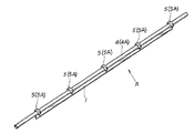
長さのある補強板1に、建築用縦材3間などの取付箇所2間に架設状態にして固定される建築用横材4に抱持固定し得るクランプ部5を設け、このクランプ部5を前記建築用横材4に固定することで、前記補強板1が建築用横材4に沿設状態に配設し、この補強板1の板面方向が上下方向となる縦設状態で建築用横材4に固定し得るように前記クランプ部5を前記補強板1に設けた構成としたことを特徴とする建築用横材補強具に係るものである。
The long reinforcing plate 1 is provided with a
また、前記クランプ部5を前記建築用横材4に固定した際、長さのある前記補強板1がこの建築用横材4に略平行な沿設状態で配設し得るように、このクランプ部5の前記補強板1への配設位置を設定すると共に、前記補強板1を前記建築用横材4の下方に配設して固定し得るように、前記クランプ部5を構成したことを特徴とする請求項1記載の建築用横材補強具に係るものである。
In addition, when the
また、前記クランプ部5は、前記建築用横材4としてのパイプ4Aに抱持固定し得るパイプクランプ5Aを採用したことを特徴とする請求項1,2のいずれか1項に記載の建築用横材補強具に係るものである。
Moreover, the said
また、帯板状の前記補強板1の長さ方向の一側縁に、この補強板1の長さ方向に間隔を置いて前記クランプ部5を複数突設したことを特徴とする請求項1〜3のいずれか1項に記載の建築用横材補強具に係るものである。
Further, a plurality of the
また、前記補強板1と前記クランプ部5とは一体物で構成せずに別部品により構成し、この別部品の補強板1とクランプ部5とをクランプ連結手段6により着脱自在に連結し得るように構成したことを特徴とする請求項1〜4のいずれか1項に記載の建築用横材補強具に係るものである。
Further, the reinforcing plate 1 and the
また、前記クランプ連結手段6は、前記クランプ部5を有し前記補強板1に重合可能なクランプ付連結体7を備え、このクランプ付連結体7を前記補強板1に重合した際に連通する連結孔8をこのクランプ付連結体7と補強板1とに設け、この連通する連結孔8に止着具9を着脱自在に挿通止着することで、補強板1とクランプ付連結体7とを連結して補強板1にクランプ部5を設ける構成としたことを特徴とする請求項5記載の建築用横材補強具に係るものである。
The clamp connecting means 6 includes a clamped connecting
また、帯板状の前記補強板1は、その長さ方向に他の帯板状の補強板1を並設して並設連結手段10により連結し得るように構成したことを特徴とする請求項1〜6のいずれか1項に記載の建築用横材補強具に係るものである。
The strip-shaped reinforcing plate 1 is configured such that another strip-shaped reinforcing plate 1 is juxtaposed in the length direction and can be connected by the
また、帯板状の前記補強板1は、その長さ方向と直交する方向に他の帯板状の補強板1を並設して並設連結手段10により連結し得るように構成したことを特徴とする請求項1〜7のいずれか1項に記載の建築用横材補強具に係るものである。
Further, the band plate-shaped reinforcing plate 1 is configured such that another band plate-shaped reinforcing plate 1 can be arranged in parallel in a direction orthogonal to the length direction and can be connected by the
また、前記並設連結手段10は、並設した前記各補強板1間に架設状態にして重合する連結板11を備え、この連結板11を各補強板1に重合した際に連通する連結孔8をこの連結板11と各補強板1とに設け、この連通する連結孔8に止着具9を挿通止着することで、並設する各補強板1と連結板11とを連結して並設する各補強板1をこの連結板11を介して連結する構成としたことを特徴とする請求項7,8のいずれか1項に記載の建築用横材補強具に係るものである。
Further, the side-by-side connecting means 10 includes a connecting
また、建築用縦材3と建築用横材4とを直交あるいは傾斜状態に連結固定して構築される骨組構造体12を有する建築構造物Bの構築方法であって、前記建築用横材4に、前記請求項1〜9のいずれか1項に記載の建築用横材補強具Aを、前記クランプ部5を介して固定することを特徴とする建築構造物の構築方法に係るものである。
Moreover, it is a construction method of a building structure B having a
また、少なくとも前記建築用横材4がパイプ4Aを採用して構成された建築構造物Bの構築方法であって、前記建築用横材補強具Aの前記クランプ部5は、前記建築用横材4としてのパイプ4Aに抱持固定し得るパイプクランプ5Aを採用し、このパイプクランプ5Aを建築用横材4としてのパイプ4Aに抱持固定することで建築用横材4に前記建築用横材補強具Aを固定することを特徴とする請求項10記載の建築構造物の構築方法に係るものである。
Further, at least the
本発明は上述のように構成したから、建築用横材にクランプ部を介して本発明の建築用横材補強具を固定すると、建築用横架材にこの建築用横架材を変形させようとする荷重が加わった際に、この荷重が建築用横架材だけでなく補強板によっても支持されることになり、しかも、この補強板は、その板面方向が上下方向となる縦設状態で建築用横材に固定されるために、建築用横材に対して常に加わるこの建築用横材を上下方向に変形させようとする荷重に対して強い耐変形強度を発揮して建築用横材の変形を防止できることになり、従って、本補強具によって補強した建築用横材は耐変形強度が著しく増すことになるため、長い建築用横材であっても建築用横材が下方へ撓み変形するようなことがなく、よって、設計の自由度が向上し、補強した長い建築用横材の下方に広い間口を確保したり、補強した建築用横材の上方に耐荷重性の高いフロアスペースを構築したりすることが可能となる。 Since the present invention is configured as described above, when the architectural cross member reinforcing tool of the present invention is fixed to the building cross member via the clamp portion, the building cross member will be deformed to the building cross member. When this load is applied, this load will be supported not only by the building horizontal member but also by the reinforcing plate, and the reinforcing plate is in a vertically installed state in which the plate surface direction is the vertical direction. Because it is fixed to the building cross member, the building cross member is always applied to the building cross member. Therefore, the structural cross member reinforced by this reinforcing tool will have a significantly increased deformation resistance, so that even if it is a long structural cross member, the structural cross member will bend downward. There is no deformation, so the degree of freedom in design is improved and compensation is made. By ensuring a wide frontage below the long building crosspiece that makes it possible or build high floor space of load bearing above the reinforced building crosspiece.
従って、例えば、本補強具を固定した長い建築用横材を使用することで、自動車二台分以上の開口幅の出入り口(間口)を有するガレージを構築したり、二階の床を支える一階の天井部分の建築用横材に本補強具を固定して補強することで、非常に強度が高く耐荷重性に秀れた二階の床を有する二階建ての物置小屋などを構築することが可能となるなど、極めて実用性に秀れた画期的な建築用横材補強具となる。 Therefore, for example, by using a long building cross member with this reinforcing fixture fixed, a garage having an entrance (frontage) with an opening width of two or more cars can be constructed, or the first floor supporting the second floor It is possible to construct a two-story storage shed with a second floor that is very strong and has excellent load resistance by fixing and reinforcing this reinforcing tool to the building cross member on the ceiling. It becomes an epoch-making slab reinforcement for construction that is extremely practical.
また、本発明においては、建築用横材の補強材として板(補強板)を採用したから、板材は安価に且つ簡易に入手可能であるため、本発明は簡易に設計実現可能であると共に、板材は軽量で取り扱い性に秀れ、建築用横材に固定してもさほど作業性を損なうこともないなど、極めて実用性に秀れた建築用横材補強具となる。 Further, in the present invention, since a plate (reinforcing plate) is adopted as a reinforcing material for the cross member for building, the plate material can be obtained at low cost and easily, so the present invention can be easily designed and realized, The plate material is lightweight and excellent in handling property, and it is a practical cross member reinforcing member excellent in practicality.
また、請求項2記載の発明においては、補強板が建築用横材よりさほど大きく突出しないために取り扱い性に秀れると共に、骨組として組み込んだ際に他の建築材や空間を圧迫しにくいなど、一層実用性に秀れた構成の建築用横材補強具となる。
In addition, in the invention of
また、請求項3記載の発明においては、パイプ(単管など)を建築用横材として構築するこれまでの建築構造物は、安価に構築可能な反面パイプ自体の強度が不足がちであるために設計上の制約があるという問題があったが、本補強具により建築用横材として用いるパイプに簡単に強度を持たせることができるので、設計の自由度が向上してただのパイプだけでは実現不可能だった出入り口(間口)の広いガレージや耐荷重性の高い二階床を備えた二階建ての物置小屋などを簡易に構築することが可能となる一層実用性に秀れた構成の建築用横材補強具となる。
Moreover, in the invention of
また、請求項4記載の発明においては、前記作用・効果を確実に発揮する本発明の建築用横材補強具を簡易に設計実現可能となる。
In the invention according to
また、請求項5記載の発明においては、例えば、補強板にクランプ部を溶接するような構成に比して、補強板にクランプ部を設ける構成(クランプ連結手段)を簡易に設計実現可能であると共に、補強板に対して最適な位置にクランプ部を連結できるような構成とすることも簡易に設計実現可能であるなど、一層実用性に秀れた構成の建築用横材補強具となる。
Further, in the invention described in
また、請求項6記載の発明においては、前記クランプ連結手段を簡易な構造により容易に設計実現可能となる一層実用性に秀れた構成の建築用横材補強具となる。
Further, in the invention described in
また、請求項7記載の発明においては、さほど長さのない補強板であっても、建築用横材の長さに応じて継ぎ足し連結して対応することができるので汎用性に秀れ、これにより補強板は短いものでも構成可能であるので、一層取り扱い性に秀れた本建築用補強具を実現可能であるなど、極めて実用性に秀れた構成の建築用横材補強具となる。
Further, in the invention according to
また、請求項8記載の発明においては、建築用横材に対する補強強度を一層向上させることができる一層実用性に秀れた構成の建築用横材補強具となる。
Moreover, in invention of
また、請求項9記載の発明においては、補強板を並設して連結する並設連結手段を簡易な構造により容易に設計実現可能となる一層実用性に秀れた構成の建築用横材補強具となる。
Further, in the invention according to
また、請求項10記載の発明においては、前記作用・効果を発揮する極めて実用性に秀れた画期的な建築構造物の構築方法となる。
In the invention according to
また、請求項11記載の発明においては、単管などのパイプによる建築構造物の建築用横材(横設パイプ)に簡単に強度を持たせることができるので、設計の自由度が向上して出入り口(間口)の広いガレージや耐荷重性の高い二階床を備えた二階建ての物置小屋などを簡易に且つ安価に構築可能となる一層実用性に秀れた構成の建築構造物の構築方法となる。
Further, in the invention according to
好適と考える本発明の実施形態(発明をどのように実施するか)を、図面に基づいて本発明の作用を示して簡単に説明する。 Embodiments of the present invention that are considered suitable (how to carry out the invention) will be briefly described with reference to the drawings, illustrating the operation of the present invention.
建築用横材4に、クランプ部5を抱持固定して本発明の建築用横材補強具Aを固定することができる。
The building cross member reinforcing tool A of the present invention can be fixed by holding and fixing the
すると、補強板1が建築用横材4に沿設状態に配設すると共に、この補強板1は、その板面方向が上下方向となる縦設状態で建築用横材4に固定されることになる。
Then, the reinforcing plate 1 is arranged along the
そのため、建築用横架材4にこの建築用横架材4が変形しようとする荷重が加わった際には、この荷重が建築用横架材4だけでなく前記補強板1によっても支持されることになるので、建築用横架材4の耐変形強度が向上する。
For this reason, when a load is applied to the building
しかも、この補強板1は、その板面方向が上下方向となる縦設状態で建築用横材4に固定されるので、この補強板1の強度は特に建築用横材4を上下方向に変形させようとする荷重に対して強い耐変形強度を発揮する。
Moreover, since the reinforcing plate 1 is fixed to the
即ち、板は、その板厚方向への変形荷重に対しては弱いが、板幅方向への変形荷重に対しては強い耐変形強度を発揮する性質を有している。この板の性質を利用し、建築用横材4が上下方向に変形しようとすることに抗して、補強板1が最も高い耐変形強度を発揮する状態(板面方向)となるようにして建築用横材4に固定されるため、建築用横材4の上下方向への変形が極めて強固に防止される。
In other words, the plate is weak against a deformation load in the plate thickness direction, but has a property of exhibiting a strong deformation resistance against a deformation load in the plate width direction. Utilizing the properties of this plate, the reinforcing plate 1 is in a state (plate surface direction) in which the reinforcing plate 1 exhibits the highest deformation resistance against the fact that the
そのため、建築構造物Bは、建築用縦材3と建築用横材4とを直交あるいは傾斜状態に連結固定して骨組構造体12を構築するものが一般的であり、例えば支柱として機能する左右の建築用縦材3(取付箇所2)間に架設状態にして本補強具Aを固定した建築用横材4を設置固定すると、この建築用横材4には、図15に示すように常にこの建築用横材4を下方へ撓ませようとする荷重が加わるが、この荷重が補強板1の補強作用によって良好に支えられて建築用横材4の変形が防止されることになる。
Therefore, the building structure B is generally constructed by constructing the
従って、このように本補強具Aによって建築用横材4は耐変形強度が著しく増すことになるため、たとえ強度不足の懸念のある長い建築用横材4を使用した場合であっても、本補強具Aで補強することにより、その途中に補強用の支柱などを設置せずとも建築用横材4が下方へ撓み変形するようなことがなく、よって、この長い建築用横材4の下方に支柱のない広い間口(例えば出入り口21など)を確保することが可能となる。
Therefore, since the
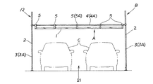
従って、例えばガレージを構築する場合には、たとえ建築用横材4に強度不足の懸念があったとしても、長い建築用横材4に本補強具Aを固定して使用することでこの建築用横材4の下方に自動車C二台分以上の開口幅の出入り口21(間口)を形成することが可能となるので、自動車Cを二台横に並べて駐車できて出し入れも容易に行われる実用性に秀れたガレージを構築することが可能となる。
Therefore, for example, when constructing a garage, even if there is a concern about insufficient strength of the
また、例えば、二階建ての物置小屋などを構築する場合に、二階の床を支える一階の天井部分の建築用横材4に本補強具Aを固定して補強することとすれば、非常に強度が高く、耐荷重性に秀れた二階の床を形成することができ、二階にまでも重量物を多量に保管できる実用的な物置小屋が完成することになる。
Also, for example, when building a two-story storage shed, etc., if this reinforcing tool A is fixed and reinforced to the
特に、単管などのパイプ4Aを少なくとも建築用横材4として構築する建築構造物Bにおいては、パイプ4Aの強度がさほど強くはないために建築用横材4として採用した横設パイプ4Aの長さが長いと、この横設パイプ4Aが下方へ撓み変形してしまうことが往々にしてあり、これが原因で設計上の制約を受けるという問題があったが、この横設パイプ4Aに本補強具Aを固定して補強することで横設パイプ4Aの撓み変形が防止されることになり、このような建築材自体に強度のないものを用いる建築構造物Bにおいては、本補強具Aは極めて有用となる。即ち、建築材自体に強度がなくとも、本補強具Aを使用することで設計の自由度が著しく向上し、ただのパイプだけでは実現不可能であった出入り口21(間口)の広いガレージや耐荷重性の高い二階床を備えた二階建ての物置小屋などを簡易に且つ非常に安価に構築可能となる。
In particular, in the building structure B in which a
また、補強材として採用した板材(補強板1)は、安価に且つ簡易に入手可能であるため本発明の補強板1は簡易に設計実現可能であると共に、板材は軽量で取り扱い性に秀れる上、建築用横材4に固定してもさほど作業性を損なうこともないので実用的である。
Further, since the plate material (reinforcing plate 1) employed as the reinforcing material can be obtained inexpensively and easily, the reinforcing plate 1 of the present invention can be easily designed and realized, and the plate material is light and excellent in handleability. Moreover, even if it is fixed to the
また、例えば、前記クランプ部5を前記建築用横材4に固定した際、長さのある前記補強板1がこの建築用横材4に略平行な沿設状態で配設し得るように、このクランプ部5の前記補強板1への配設位置を設定すると共に、前記補強板1を前記建築用横材4の下方に配設して固定し得るように、前記クランプ部5を構成すれば、補強板1が建築用横材4と平行に沿設しているために、本補強具Aを固定した建築用横材4の取り扱い性が大きく損なわれるようなことがない上、構造物内の空間を圧迫しにくく、また、補強板1が建築用横材4の下方に配設するため、この建築用横材4上方への床材17などの取り付けに際して補強板1が邪魔とならないなど、一層実用的となる。
Also, for example, when the
また、例えば、前記クランプ部5は、前記建築用横材4としてのパイプ4Aに抱持固定し得るパイプクランプ5Aを採用すれば、安価に構築可能なパイプ4A(単管など)による建築構造物Bに本補強具により簡単に強度を持たせることができ、これにより出入り口21(間口)の広いガレージや耐荷重性の高い二階床を備えた二階建ての物置小屋などを簡易に設計実現可能となるなど、一層実用的となる。
In addition, for example, if the
また、例えば、帯板状の前記補強板1の長さ方向の一側縁に、この補強板1の長さ方向に間隔を置いて前記クランプ部5を複数突設した構成とすれば、複数のクランプ部5により本補強具Aを建築用横材4に強固に固定して確実に補強作用を付与することができる上、補強板1が帯板状であるため、この補強板1の長さ方向の一側縁に、建築用横材4に対して抱持固定する複数のクランプ部5を簡易に配置可能であるなど、一層実用的となる。
Further, for example, if a plurality of the
また、例えば、前記補強板1と前記クランプ部5とは一体物で構成せずに別部品により構成し、この別部品の補強板1とクランプ部5とをクランプ連結手段6により着脱自在に連結し得るように構成すれば、補強板1にクランプ部5を溶接固定するような構成に比べて製作が容易であり、しかも、例えば、より良い補強作用が建築用横材4に対して付与されるように補強板1の適所へ所望数のクランプ部5を自由に連結配置できたり、他の建築材に対してクランプ部5が干渉しないようにクランプ部5を配置できるような構成も簡易に設計実現可能であるなど、一層実用的となる。
Further, for example, the reinforcing plate 1 and the
また、例えば、帯板状の前記補強板1は、その長さ方向に他の帯板状の補強板1を並設して並設連結手段10により連結し得るように構成すれば、さほど長さのない補強板1であっても、建築用横材4の長さに応じて継ぎ足し連結して対応使用することができ、これにより補強板1はさほど長さのないものでも構成可能であるので、取り扱い性に秀れた本建築用補強具を実現可能であるなど、一層実用的となる。
Further, for example, the band plate-like reinforcing plate 1 is so long that it is configured so that another band plate-like reinforcing plate 1 can be arranged in parallel in the length direction and can be connected by the parallel connecting
また、例えば、帯板状の前記補強板1は、その長さ方向と直交する方向に他の帯板状の補強板1を並設して並設連結手段10により連結し得るように構成すれば、複数の帯板状の補強板1を幅方向に並べて連結した幅広な集合体を構成することで、建築用横材4に対する補強強度を一層向上させることができ、一層実用的となる。
Further, for example, the strip-shaped reinforcing plate 1 is configured such that another strip-shaped reinforcing plate 1 is juxtaposed in a direction orthogonal to the length direction and can be coupled by the parallel coupling means 10. For example, by forming a wide assembly in which a plurality of strip-shaped reinforcing plates 1 are arranged and connected in the width direction, the reinforcing strength for the
本発明の具体的な実施例1について図1〜図7に基づいて説明する。 A first embodiment of the present invention will be described with reference to FIGS.
本実施例は、パイプ(図面は丸形の単管)を採用した建築用縦材3と建築用横材4とを直交あるいは傾斜状態に連結固定して構築される骨組構造体12を有する建築構造物Bを形成するための前記建築用横材4、即ち横設パイプ4A(横設単管4A)を補強する建築用横材補強具Aに適用している。
In this embodiment, a building having a
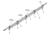
具体的には、本実施例の建築用横材補強具Aは、長さのある補強板1に、建築用縦材3(縦設パイプ3A)間などの取付箇所2間に架設状態にして固定される建築用横材4に抱持固定し得るクランプ部5を設けている。
Specifically, the building cross member reinforcing tool A according to the present embodiment is installed on the reinforcing plate 1 having a length between the attachment points 2 such as between the building vertical members 3 (
本実施例の補強板1は、金属製の帯板材を採用して構成している。 The reinforcing plate 1 of the present embodiment is configured by adopting a metal strip material.
また、クランプ部5は、パイプクランプ5A(図面では公知の単管クランプ5A)を採用して構成している。
Moreover, the
本実施例では、帯板状の補強板1の長さ方向の一側縁に、この補強板1の長さ方向に間隔を置いてクランプ部5を複数突設した構成としている。
In the present embodiment, a plurality of
また、補強板1とクランプ部5とは別製(別部品)とし、この別部品の補強板1とクランプ部5とをクランプ連結手段6により着脱自在に連結している。
Further, the reinforcing plate 1 and the
本実施例のクランプ連結手段6について説明すると、前記クランプ部5を有し前記補強板1に重合可能な帯板状のクランプ付連結体7を構成し、このクランプ付連結体7を前記補強板1に重合した際に連通する連結孔8をこのクランプ付連結体7と補強板1とに設け、この連通する連結孔8に止着具9を着脱自在に挿通止着することで、補強板1とクランプ付連結体7とを連結して補強板1にクランプ部5を突設する構成としている。
The
更に詳しくは、金属製の帯板7Aの長さ方向の一端部に、この帯板7Aの長さ方向と直交する方向が単管抱持方向となるように配した前記単管クランプ5Aを付設することで前記クランプ付連結体7を構成し、このクランプ付連結体7の帯板7Aには前記連結孔8を貫通形成している。
More specifically, the
一方、補強板1は、その長さ方向に間隔を置いた複数個所に前記連結孔8を貫通形成している。
On the other hand, the reinforcing plate 1 has the connecting
そして、クランプ付連結体7の帯板7Aを補強板1に重合すると共に、帯板7Aと補強板1とが互いに直交するように配した上で双方の連結孔8を連通させ、この連通させた連結孔8・8にボルト9A・ナット9Bを採用した止着具9のボルト9Aを挿通してナット9B止めすることで、補強板1にクランプ付連結体7(の帯板7A)を固定し、補強板1の一側縁よりクランプ部5(単管クランプ5A)が突設するように構成している。
Then, the
また、この際、補強板1に形成した複数の連結孔8を選択してクランプ付連結体7を固定することで、補強板1に対するクランプ部5の突設位置を変更したり、補強板1に設けるクランプ部5の数を変更することができる構成としている。
At this time, by selecting a plurality of connecting
また、本実施例では、補強板1の長さ方向に略等間隔を置いて複数のクランプ部5が突設するようにすると共に、各クランプ部5が補強板1の一側縁に対して等しい突出度で突設するように、複数のクランプ付連結体7を固定補強板1に固定している。
Further, in the present embodiment, the plurality of
このように構成した本実施例の建築用補強具Aを、各クランプ部5(単管クランプ5A)を抱持固定することで建築用横材4としての横設単管4Aに固定すると、補強板1が横設単管4Aと略平行状態で沿設固定することになり、この横設単管4Aにこの建築用横架材4が変形しようとする荷重が加わった際には、この荷重が建築用横架材4だけでなく前記補強板1によっても支持されることとなって、建築用横架材4の耐変形強度が向上する構成としている。
When the construction reinforcing tool A of the present embodiment configured as described above is fixed to the horizontal
また、単管クランプ5Aは、横設単管4Aに対して360度範囲に自由に補強板1を向けて固定可能であるが、本実施例ではこの補強板1を、前記建築用横材4の下方に配設すると共に、その板面方向が上下方向となる縦設状態となるようにして建築用横材4に固定する。これにより、この補強板1の強度は特に建築用横材4を上下方向に変形させようとする荷重に対して強い耐変形強度を発揮する。即ち、板は、その板厚方向への変形荷重に対しては弱いが、板幅方向への変形荷重に対しては強い耐変形強度を発揮する性質を有している。この板の性質を利用し、建築用横材4が上下方向に変形しようとすることに抗して、補強板1が最も高い耐変形強度を発揮する状態(板面方向)となるようにして建築用横材4に固定することにより、建築用縦材3間(取付箇所2)間に架設状態にして固定される建築用横材4には、常にこの建築用横材4を下方へ撓ませようとする荷重が加わるが、この荷重が補強板1の補強作用によって良好に支えられて建築用横材4の変形が防止されることになる構成としている。
In addition, the
また、本実施例では、細帯状の補強板1を図示しているが、この補強板1の幅(長さ方向と直交する幅)が広い太帯状のものとすることにより、補強強度を向上させることができる構成である。 Further, in the present embodiment, the thin strip-shaped reinforcing plate 1 is illustrated, but the reinforcing strength is improved by making the reinforcing plate 1 have a wide width (width orthogonal to the length direction). It is the structure which can be made to do.
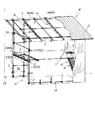
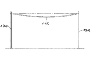
図1は、本実施例の建築用補強具Aを固定した建築用横材4(横設単管4A)を用いてガレージ付の二階建て物置小屋(建築構造物B)を構築した場合を示している。
FIG. 1 shows a case where a two-story building shed with a garage (building structure B) is constructed using a building cross member 4 (horizontal
一階部分はガレージスペース、二階部分は物置スペースである。図面では、一階の天井部分の建築用横材4と、二階天井部分の建築用横材4と、一階と二階の間に設けられた階段13の支持材としての建築用横材4に本補強具Aを固定して補強している。
The first floor is a garage space, and the second floor is a storage space. In the drawing, the
一階のガレージ部分は、一階天井部分に複数の長い建築用横材4を使用し、この長い建築用横材4に本補強具Aを固定することで自動車C二台分以上の開口幅の出入り口21(間口)を形成している(図4参照。)。出入り口21上方の長い建築用横材4(横設単管4A)は、本補強具Aで補強することにより、その途中に補強用の支柱などを設置せずとも下方へ撓み変形するようなことがなく、よって、この長い横設単管4Aの下方に支柱のない広い出入り口21が確保される。また、この場合、本補強具Aを固定した横設単管4Aは、骨組構造体12に間隔を置いて配置する縦設パイプ(単管)3Aを取付箇所2としてこの取付箇所2間に水平状態で架設固定している。
The garage part on the first floor uses a plurality of long
また、この一階天井部分の複数の横設単管4A間に垂木クランプ16などを介して床材17固定用の桟木15を架設固定し、この桟木15上に床材17を張設固定して物置フロアを形成している(図5参照。)。この物置フロアは、各横設単管4Aが本補強具Aにより補強されて高強度を発揮するために、床の強度が高く、耐荷重性に秀れる。また、この場合、本補強具Aを固定した横設単管4Aは、骨組構造体12の同じ高さに間隔を置いて水平に設置される各横材を取付箇所2としてこの取付箇所2間に水平状態で架設固定している。
In addition, a
また、二階天井部分の複数の横設単管4A間に図示省略の垂木を架設固定し、この垂木上に屋根材18を葺いてある(図6参照。)。このようにして構成した屋根は、各横設単管4Aが本補強具Aにより補強されて高強度を発揮するために、耐荷重性が高く、多量の積雪22にも耐えることができる。従って、屋根強度が高く、豪雪地域での使用に耐える建築構造物Bとなる。また、この場合、本補強具Aを固定した横設単管4Aは、骨組構造体12の異なる高さに間隔を置いて水平に設置される各横材を取付箇所2としてこの取付箇所2間に傾斜状態で架設固定し、この傾斜する各横設単管4A上に勾配屋根を形成している。
Further, a rafter (not shown) is fixed between a plurality of horizontal
また、階段13は、一対の横設単管4A間に、仮設足場の構築に用いられる足場用階段部品14を多数架設固定することで構築している(図7参照。)。このように構成した階段13は、この階段13の支持材としての建築用横材4が本補強具Aによって補強されているために、強度が高く耐荷重性に秀れた階段13ができあがる。また、この場合、本補強具Aを固定した横設単管4Aは、骨組構造体12の一階天井部分に水平に設置される横材と、地面とを取付箇所2としてこの取付箇所2間に傾斜状態で架設固定し、この傾斜する各横設単管4Aに傾斜状の階段13を形成している。
The
尚、請求項1中の「建築用横材4」なる記載は、水平状態に設置される横材だけを意味するのではなく、例えば、勾配屋根や階段13を形成するために傾斜状態に設置される横材をも含む意味合いで用いている。
It should be noted that the term “building
本発明の具体的な実施例2について図8に基づいて説明する。 A second embodiment of the present invention will be described with reference to FIG.
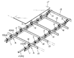
本実施例は、前記実施例1において、補強板1を、その長さ方向に他の帯板状の補強板1を並設して並設連結手段10により連結し得るように構成した場合である。即ち、この並設連結手段10により補強板1を並設連結することにより、補強板1の長さを取付箇所2間の長さに応じて延長することができる構成としている。
This embodiment is a case in which the reinforcing plate 1 in the first embodiment is configured such that another strip-like reinforcing plate 1 is juxtaposed in the length direction and can be connected by the parallel connecting
具体的には、並設連結手段10は、並設した前記各補強板1間に架設状態にして重合する連結板11を備え、この連結板11を各補強板1に重合した際に連通する連結孔8をこの連結板11と各補強板1とに設け、この連通する連結孔8に止着具9を挿通止着することで、並設する各補強板1と連結板11とを連結して並設する各補強板1をこの連結板11を介して連結する構成としている。
Specifically, the juxtaposed connecting
更に詳しくは、連結板11は補強板1と同等の板幅を有する短い金属製の帯板材を採用して構成し、この連結板11には、長さ方向に小間隔を置いて前記連結孔8を複数個所(図面では四箇所)に貫通形成している。
More specifically, the connecting
一方、各補強板1には、その突合せ端部に夫々長さ方向に小間隔を置いて(連結板11の連結孔8の並設間隔と等間隔を置いて)前記連結孔8を複数箇所(図面では、一つの補強板1につき二箇所)に貫通形成している。
On the other hand, each reinforcing plate 1 is provided with a plurality of connecting
そして、各補強板1の端部同士を突き合わせた上で、この突合せ端部に連結板11を重合して各々の連結孔8を連通させ、この連通させた各連結孔8・8にボルト9A・ナット9Bを採用した止着具9のボルト9Aを挿通してナット9B止めすることで、連結板11と各補強板1とを連結し、これにより連結板11を介して各補強板1が並設状態で連結して補強板1の長さを延長することができる構成としている。
Then, after the end portions of the reinforcing plates 1 are butted together, the connecting
他の構成は、前記実施例1と同様である。 Other configurations are the same as those of the first embodiment.
尚、本実施例では、二枚の補強板1を連結した場合を示したが、並設連結手段10により三枚以上の補強板1をその長さ方向に連結して補強板1の長さを延長することが可能である。また、止着具9,連結板11を取り外すことで連結した各補強板1を分離することも可能である。
In this embodiment, the case where two reinforcing plates 1 are connected is shown. However, the length of the reinforcing plate 1 is obtained by connecting three or more reinforcing plates 1 in the length direction by the parallel connecting
本発明の具体的な実施例3について図9,図10に基づいて説明する。 A specific third embodiment of the present invention will be described with reference to FIGS.
本実施例は、前記実施例1において、補強板1を、その長さ方向と直交する方向に他の帯板状の補強板1を並設して並設連結手段10により連結し得るように構成した場合である。即ち、この並設連結手段10により補強板1を並設連結して実質的に補強板1の幅を拡大することにより、補強作用が向上する構成としている。
In this embodiment, in the first embodiment, the reinforcing plate 1 can be connected by the parallel connecting
具体的には、並設連結手段10は、並設した前記各補強板1間に架設状態にして重合する連結板11を備え、この連結板11を各補強板1に重合した際に連通する連結孔8をこの連結板11と各補強板1とに設け、この連通する連結孔8に止着具9を挿通止着することで、並設する各補強板1と連結板11とを連結して並設する各補強板1をこの連結板11を介して連結する構成としている。
Specifically, the juxtaposed connecting
更に詳しくは、本実施例では、クランプ付連結体7の帯板7Aの長さを、実施例1よりも長く形成し、この帯板7Aには、その長さ方向に小間隔を置いて複数個所(図面では三箇所)に連結孔8を貫通形成している。
More specifically, in this embodiment, the length of the
本実施例では、このクランプ付連結体7の帯板7Aを前記連結板11としている。即ち、クランプ部5を補強板1に連結するための帯板7Aが、補強板1を並べて連結するための連結板11としての機能を兼ねる(クランプ連結手段6が並設連結手段10を兼ねる)構成としている。
In this embodiment, the
一方、各補強板1には、夫々長さ方向に小間隔を置いて前記連結孔8を複数箇所に貫通形成している。
On the other hand, each reinforcing plate 1 is formed with the connecting
そして、各補強板1を、その長さ方向と直交する方向に並べて突き合わせた上で、この連結板11としての帯板7Aを重合して各々の連結孔8を連通させ、この連通させた各連結孔8・8にボルト9A・ナット9Bを採用した止着具9のボルト9Aを挿通してナット9B止めすることで、連結板11(帯板7A)と各補強板1とを連結し、これにより連結板11を介して各補強板1が幅方向に並設状態で連結するように構成している。同時にクランプ部5(クランプ付連結体7)が各補強板1に連結する構成である。
Then, after each reinforcing plate 1 is aligned and abutted in a direction orthogonal to the length direction, the
また、この際、帯板7Aに形成した複数の連結孔8を選択することで、補強板1の一側縁に対するクランプ部5の突出度合いを調整変更することができるし、補強板1に形成した複数の連結孔8を選択することで、補強板1に対するクランプ部5の突設位置を変更することができる構成としている。
At this time, by selecting a plurality of connecting
また、図10は、本実施例の建築用横材補強具Aを固定して補強した長い横設単管4Aを用いて、前記実施例1で示したガレージよりも出入り口21の開口幅(間口)を拡大形成し、この拡大させたスペースに階段13を形成した場合を示している。また、この図では、前記実施例2の連結板11を用いた並設連結手段10を併用して補強板1をその長さ方向に連結して長く延長させた場合を示している。
Further, FIG. 10 shows the opening width of the entrance / exit 21 (frontage) than the garage shown in the first embodiment by using the long horizontal
この図10からもわかるように、本実施例の並設連結手段10と前記実施例3の並設連結手段10とは実質的に同じ構成であり、連結板11の方向を補強板1の並設方向に応じて変更することで、補強板1をその長さ方向に連結するか、幅方向に連結するかを選択できる構成である。
As can be seen from FIG. 10, the side-by-side connection means 10 of this embodiment and the side-by-side connection means 10 of the third embodiment have substantially the same configuration, and the direction of the
他の構成は、前記実施例1と同様である。 Other configurations are the same as those of the first embodiment.
尚、本実施例では、二枚の補強板1を連結した場合を示したが、並設連結手段10の連結板11の長さを延長することにより、三枚以上の補強板1をその幅方向に連結して補強板1の幅を広くして補強強度を向上させることが可能である。また、止着具9,連結板11を取り外すことで連結した各補強板1を分離することも可能である。この点は、後述の実施例4,5についても同様である。
In this embodiment, the case where two reinforcing plates 1 are connected is shown. However, by extending the length of the connecting
本発明の具体的な実施例4について図11に基づいて説明する。 A fourth embodiment of the present invention will be described with reference to FIG.
本実施例は、前記実施例3と同様の並設連結手段10により補強板1を幅方向に並設して連結し得るように構成した場合であるが、更に、補強板1の長さ方向の一側縁からだけでなく、他側縁からも、この補強板1の長さ方向に間隔を置いて前記クランプ部5を複数突設して、上下に並設状態に設けられた建築用横材4(横設単管4A)の双方に対して本補強具Aを固定し得るように構成した場合である。
The present embodiment is a case in which the reinforcing plates 1 can be connected in parallel in the width direction by the parallel connecting
具体的には、各補強板1に形成する連結孔8の数を増やし、クランプ付連結体7を上下逆向きにして各補強板1に連結固定した場合を示している。
Specifically, the case where the number of connecting
このような構成とすることにより、上下に並設する二本の横設単管4Aの双方に対して補強作用を付与することができるので、一層強度の高い建築構造物B(骨組構造体12)を構築できることになる。
By adopting such a configuration, it is possible to give a reinforcing action to both of the two horizontal
他の構成は、前記実施例3と同様である。 Other configurations are the same as those of the third embodiment.
本発明の具体的な実施例5について図12に基づいて説明する。
A
本実施例は、前記実施例3において、連結板11の構成を異ならせた場合である。
This embodiment is a case where the configuration of the connecting
具体的には、本実施例の連結板11は、二枚の補強板1をその長さ方向と直交する幅方向に並べた際の幅寸法と同等の長さ寸法を有する短い金属製の帯板材を採用して構成し、この連結板11には、長さ方向に小間隔を置いて前記連結孔8を複数個所(図面では二箇所)に貫通形成している。
Specifically, the connecting
そして、各補強板1を、その長さ方向と直交する方向に並べて突き合わせた上で、この連結板11を各補強板1に掛け渡すように重合して各々の連結孔8を連通させ、この連通させた各連結孔8・8にボルト9A・ナット9Bを採用した止着具9のボルト9Aを挿通してナット9B止めすることで、連結板11と各補強板1とを連結し、これにより連結板11を介して各補強板1が幅方向に並設状態で連結するように構成している。
Then, after each reinforcing plate 1 is aligned and abutted in a direction orthogonal to its length direction, the connecting
即ち、クランプ付連結体7の帯板7Aが連結板11を兼用する構成でなく、別個に連結板11を用いて並設連結手段10を構成した場合である。
That is, the
他の構成は、前記実施例3と同様である。 Other configurations are the same as those of the third embodiment.
本発明の具体的な実施例6について図13,図14に基づいて説明する。 A sixth embodiment of the present invention will be described with reference to FIGS.
本実施例は、前記実施例1において、クランプ付連結体7を用いず、補強板1の長さ方向の一側縁に直接単管クランプ5Aを溶接することで、補強板1の長さ方向の一側縁に、この補強板1の長さ方向に間隔を置いてクランプ部5を複数突設した構成とした場合である。
In this embodiment, the longitudinal direction of the reinforcing plate 1 is obtained by welding the
他の構成は前記実施例1と同様である。 Other configurations are the same as those of the first embodiment.
尚、本発明は、実施例1〜6に限られるものではなく、各構成要件の具体的構成は適宜設計し得るものである。 In addition, this invention is not restricted to Examples 1-6, The concrete structure of each component can be designed suitably.
例えば、本補強具Aを固定する建築用横材4は、本実施例で示したパイプ4A(単管4A)に限定されるものではなく、どのような横材に対しても適用可能であるが、もともと補強なしでも高強度を誇るH鋼などに適用するよりは、パイプ材やアングル材やチャンネル材などの建築用横材4として用いた際に強度不足の懸念があるものに適用することが好ましく、このような横材を採用することにより有用性が向上する。また、本実施例では、パイプ4Aとして特に丸形の単管4Aを採用した場合を示したが、市販の角形パイプ材や他のパイプ材に固定できるような構成としても良い。
For example, the
また、本実施例では、単管による建築構造物Bとしてガレージ付の物置小屋を構築した場合を示したが、他の屋根付の建築構造物Bを構築しても良いし、例えば、工事現場での歩行者用通路や、歩道の屋根などのような家屋形でない建築構造物Bを構築することも可能である。 Moreover, in the present Example, although the case where the storage shed with a garage was constructed | assembled as the building structure B by a single pipe | tube was shown, you may build the building structure B with another roof, for example, a construction site It is also possible to construct a building structure B that is not a house shape such as a pedestrian walkway or a sidewalk roof.
1 補強板
2 取付箇所
3 建築用縦材
4 建築用横材
4A パイプ
5 クランプ部
5A パイプクランプ
6 クランプ連結手段
7 クランプ付連結体
8 連結孔
9 止着具
10 並設連結手段
11 連結板
12 骨組構造体
A 建築用横材補強具
B 建築構造物
DESCRIPTION OF SYMBOLS 1
10 Side-by-side connection means
11 Connecting plate
12 Frame structure A Reinforcing bar for building construction B Building structure
Claims (11)
Priority Applications (1)
| Application Number | Priority Date | Filing Date | Title |
|---|---|---|---|
| JP2007166185A JP4628401B2 (en) | 2007-06-25 | 2007-06-25 | Building cross member reinforcement and construction method of building structure |
Applications Claiming Priority (1)
| Application Number | Priority Date | Filing Date | Title |
|---|---|---|---|
| JP2007166185A JP4628401B2 (en) | 2007-06-25 | 2007-06-25 | Building cross member reinforcement and construction method of building structure |
Publications (3)
| Publication Number | Publication Date |
|---|---|
| JP2009002103A true JP2009002103A (en) | 2009-01-08 |
| JP2009002103A5 JP2009002103A5 (en) | 2009-08-13 |
| JP4628401B2 JP4628401B2 (en) | 2011-02-09 |
Family
ID=40318781
Family Applications (1)
| Application Number | Title | Priority Date | Filing Date |
|---|---|---|---|
| JP2007166185A Expired - Fee Related JP4628401B2 (en) | 2007-06-25 | 2007-06-25 | Building cross member reinforcement and construction method of building structure |
Country Status (1)
| Country | Link |
|---|---|
| JP (1) | JP4628401B2 (en) |
Cited By (2)
| Publication number | Priority date | Publication date | Assignee | Title |
|---|---|---|---|---|
| JP2011012412A (en) * | 2009-06-30 | 2011-01-20 | Shigeo Ogawa | Building material reinforcing implement and method for constructing building structure |
| JP7328917B2 (en) | 2020-02-28 | 2023-08-17 | 鹿島建設株式会社 | Reinforcing structure for roof beams and method for reinforcing roof beams |
Citations (1)
| Publication number | Priority date | Publication date | Assignee | Title |
|---|---|---|---|---|
| JPS4894606U (en) * | 1972-02-15 | 1973-11-12 |
-
2007
- 2007-06-25 JP JP2007166185A patent/JP4628401B2/en not_active Expired - Fee Related
Patent Citations (1)
| Publication number | Priority date | Publication date | Assignee | Title |
|---|---|---|---|---|
| JPS4894606U (en) * | 1972-02-15 | 1973-11-12 |
Cited By (2)
| Publication number | Priority date | Publication date | Assignee | Title |
|---|---|---|---|---|
| JP2011012412A (en) * | 2009-06-30 | 2011-01-20 | Shigeo Ogawa | Building material reinforcing implement and method for constructing building structure |
| JP7328917B2 (en) | 2020-02-28 | 2023-08-17 | 鹿島建設株式会社 | Reinforcing structure for roof beams and method for reinforcing roof beams |
Also Published As
| Publication number | Publication date |
|---|---|
| JP4628401B2 (en) | 2011-02-09 |
Similar Documents
| Publication | Publication Date | Title |
|---|---|---|
| JP4931490B2 (en) | Structure reinforcement structure and method of reinforcement | |
| KR101638239B1 (en) | Fastening structure of prefabricated deck panel in city park and nature-type's ecological river | |
| JP4628401B2 (en) | Building cross member reinforcement and construction method of building structure | |
| US20130259563A1 (en) | Universal construction bracket method and apparatus | |
| JP2009002103A5 (en) | ||
| JP5172607B2 (en) | Joint structure of flat column and beam | |
| JP5173949B2 (en) | Construction material reinforcement and construction method of building structure | |
| JP4047873B2 (en) | Heavy steel column-to-beam connection structure for low-rise residential buildings. | |
| RU62622U1 (en) | REINFORCED REINFORCED CONCRETE STRUCTURE OF A MULTI-STOREY BUILDING, FRAMEWORK CONSTRUCTION OF A FRAME, INTERIOR ELEMENT | |
| JP2009097146A (en) | Steel frame building material and building structure using the building material | |
| JP5873369B2 (en) | Building overhang structure | |
| JP5447116B2 (en) | Steel structure floor panel, steel structure floor panel joint structure and steel structure floor assembly | |
| JP2009057716A (en) | Connecting structure of building unit, and fabricated building | |
| CN212104561U (en) | Assembled building element tie-beam | |
| CN212295081U (en) | Assembly type building element for middle position of building wall | |
| JP3764020B2 (en) | Steel frame structure | |
| CN212200789U (en) | Prefabricated building element for the middle of a building intermediate floor | |
| CN212104563U (en) | Prefabricated building element for the top or bottom intermediate position of a building wall | |
| CN212200797U (en) | Prefabricated building element for the middle of a building space | |
| JP4260736B2 (en) | Steel house bearing wall structure | |
| CN212104562U (en) | Assembled building component for intersection position of two wall surfaces of building | |
| JP6860354B2 (en) | Building structure | |
| JP3963222B2 (en) | Assembled structure of bracing frames used for steel frame structures | |
| JP6783038B2 (en) | Building structure | |
| JP5484511B2 (en) | Extension hardware, extension structure and extension method |
Legal Events
| Date | Code | Title | Description |
|---|---|---|---|
| A521 | Request for written amendment filed |
Free format text: JAPANESE INTERMEDIATE CODE: A523 Effective date: 20090630 |
|
| A977 | Report on retrieval |
Free format text: JAPANESE INTERMEDIATE CODE: A971007 Effective date: 20101014 |
|
| TRDD | Decision of grant or rejection written | ||
| A01 | Written decision to grant a patent or to grant a registration (utility model) |
Free format text: JAPANESE INTERMEDIATE CODE: A01 Effective date: 20101018 |
|
| A01 | Written decision to grant a patent or to grant a registration (utility model) |
Free format text: JAPANESE INTERMEDIATE CODE: A01 |
|
| A61 | First payment of annual fees (during grant procedure) |
Free format text: JAPANESE INTERMEDIATE CODE: A61 Effective date: 20101109 |
|
| FPAY | Renewal fee payment (event date is renewal date of database) |
Free format text: PAYMENT UNTIL: 20131119 Year of fee payment: 3 |
|
| R150 | Certificate of patent or registration of utility model |
Ref document number: 4628401 Country of ref document: JP Free format text: JAPANESE INTERMEDIATE CODE: R150 Free format text: JAPANESE INTERMEDIATE CODE: R150 |
|
| R250 | Receipt of annual fees |
Free format text: JAPANESE INTERMEDIATE CODE: R250 |
|
| R250 | Receipt of annual fees |
Free format text: JAPANESE INTERMEDIATE CODE: R250 |
|
| R250 | Receipt of annual fees |
Free format text: JAPANESE INTERMEDIATE CODE: R250 |
|
| R250 | Receipt of annual fees |
Free format text: JAPANESE INTERMEDIATE CODE: R250 |
|
| R250 | Receipt of annual fees |
Free format text: JAPANESE INTERMEDIATE CODE: R250 |
|
| R250 | Receipt of annual fees |
Free format text: JAPANESE INTERMEDIATE CODE: R250 |
|
| R250 | Receipt of annual fees |
Free format text: JAPANESE INTERMEDIATE CODE: R250 |
|
| R250 | Receipt of annual fees |
Free format text: JAPANESE INTERMEDIATE CODE: R250 |
|
| LAPS | Cancellation because of no payment of annual fees |